
7 OPC UA ObjectTypes
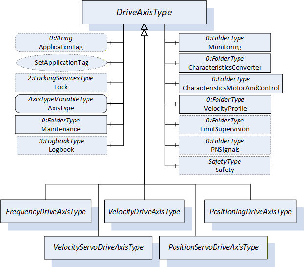
Figure 12 shows the organization of the ObjectTypes used to model Axis Objects. All Axis ObjectTypes are derived from the abstract DriveAxisType providing the functions common to all Axis ObjectTypes.
7.1 DriveAxisType
The DriveAxisType ObjectType contains the Variables and Properties common for all Axis Objects. This ObjectType is specified as abstract and cannot be used directly.
| Attribute | Value | ||||
| BrowseName | DriveAxisType | ||||
| IsAbstract | True | ||||
| References | Node Class | BrowseName | DataType | TypeDefinition | Other |
|---|---|---|---|---|---|
| Subtype of the 0:BaseObjectType defined in OPC 10000-5. | |||||
| 0:HasProperty | Variable | ApplicationTag | 0:String | 0:PropertyType | O, RO |
| 0:HasComponent | Method | SetApplicationTag | O | ||
| 0:HasComponent | Object | Lock | 2:LockingServicesType | O | |
| 0:HasProperty | Variable | AxisType | 0:Byte | AxisTypeVariableType | M, RO |
| 0:HasComponent | Object | Monitoring | 0:FolderType | M | |
| 0:HasComponent | Object | PNSignals | 0:FolderType | O | |
| 0:HasComponent | Object | LimitSupervision | 0:FolderType | O | |
| 0:HasComponent | Object | Safety | SafetyType | O | |
| 0:HasComponent | Object | CharacteristicsConverter | 0:FolderType | M | |
| 0:HasComponent | Object | CharacteristicsMotorAndControl | 0:FolderType | O | |
| 0:HasComponent | Object | VelocityProfile | 0:FolderType | M | |
| 0:HasComponent | Object | Maintenance | 0:FolderType | M | |
| 0:GeneratesEvent | ObjectType | DiagnosisAlarmType | |||
| 0:HasComponent | Object | Logbook | 3:LogbookType | O | |
| Conformance Units | |||||
|---|---|---|---|---|---|
| PDRV Measurement | |||||
| PDRV Diagnosis Events | |||||
| PDRV Signals |
General Properties
The ApplicationTag Variable contains information given by the overall application. The purpose is to provide additional semantic information about the represented Axis/DO role or labelling in the context of the specific overall application context (machine, site or plant). Therefore, plant operators and/or application engineers are responsible to set the content of the ApplicationTag with information used for site management, asset management or other administrative purposes, e.g. "Production Line <m>/Machine <n>/x-Axis". Furthermore, information like "tag-function" out of the PROFINET I&M-1 record or the "descriptor" out of the I&M-3 record may be used as content of the ApplicationTag Variable.
However, as a default, vendors might generate the ApplicationTag string out of the PROFINET device structure given by standard PROFINET configuration data as initial content of the Variable. The generic default string is "<NameOfStation>/Drive Axis Nr. <axis number>", where the <NameOfStation> is the NameOfStation of the PROFINET Drive device and the <axis number> is the PROFINET device module number representing the related PROFIdrive axis DO.
The Client can change the Value of this Variable by invoking the SetApplicationTag Method.
Before invoking a Method of the DriveAxisType Object, Clients must gain exclusive write access ("lock" the DriveAxisType Object) using the Lock Object.
The Lock Object ensures exclusive Method call for one Client. The Client locks the DriveAxisType Object by invoking the InitLock Method of the Lock Object. The Client invokes ExitLock to release the lock. The scope of the lock comprises all components of the DriveAxisType Object.
SetApplicationTag Method
This Method sets the Value of the ApplicationTag Variable. The security constraints defined in chapter 6.2 apply.
Signature
	SetApplicationTag (
		[in] 0:String	 ApplicationTag
		);
| Argument | Description |
| ApplicationTag | String containing the desired content of the ApplicationTag Variable. |
The Method Result Codes (defined in Call Service) are defined in Table 15.
| Result Code | Description |
| Good | The Method execution was successful. |
| Bad_UserAccessDenied | The user has not the authorization to execute the Method. |
| Bad_InvalidArgument | The Server is not able to apply the name. The ApplicationTag string may be too long or may contain invalid characters. The Server may also reject duplicates. |
| Bad_Locked | The DriveAxisType Object is locked by a different Client's Session. |
| Bad_RequiresLock | The DriveAxisType Object is not locked. Clients must lock the DriveAxisType Object before invoking a Method. |
| Bad_UnexpectedError | The Server is not able to execute the function because an unexpected error occurred. The Device might be temporarily unavailable or unreachable due to network failure. |
The AxisType Property contains the mechanical drive type of the represented Axis/DO modelled as AxisTypeVariableType (see 9.1).
The Value shall be 0 (reference "LINEAR_MOTION") for linear axis drives and 1 (reference "ROTATORY_MOTION") for rotatory axis drives.
Some components of the DriveAxisType have additional subcomponents which are defined in Table 16. For detailed descriptions of the Variables see Table 33.
| BrowsePath | References | NodeClass | BrowseName | DataType | TypeDefinition | Others | ||
| PNSignals | 0:HasComponent | Variable | <SignalName> | 0:Number | 0:BaseDataVariableType | MP, RO | ||
| 0:HasProperty | Variable | SignalNumber | 0:UInt16 | 0:PropertyType | O, RO | ||
| Monitoring | 0:HasComponent | Variable | AxisState | 0:UInt16 | 0:MultiStateDiscreteType | M, RO | ||
| Monitoring | 0:HasComponent | Variable | ControlPriority | 0:UInt16 | 0:MultiStateDiscreteType | M, RO | ||
| Monitoring | 0:HasComponent | Variable | ControlMode | 0:UInt16 | 0:MultiStateDiscreteType | O, RO | ||
| Monitoring | 0:HasComponent | Variable | OutputCurrent | 0:Float | 0:AnalogUnitType | O, RO | ||
| Monitoring | 0:HasComponent | Variable | Torque | 0:Float | 0:AnalogUnitType | O, RO | ||
| Monitoring | 0:HasComponent | Variable | Force | 0:Float | 0:AnalogUnitType | O, RO | ||
| Monitoring | 0:HasComponent | Variable | Power | 0:Float | 0:AnalogUnitType | O, RO | ||
| Monitoring | 0:HasComponent | Variable | MotorTemperature | 0:Float | TemperatureVariableType | O, RO | ||
| Monitoring | 0:HasComponent | Variable | ConverterTemperature | 0:Float | TemperatureVariableType | O, RO | ||
| Monitoring | 0:HasComponent | Variable | DeviceTemperature | 0:Float | TemperatureVariableType | O, RO | ||
| Monitoring | 0:HasComponent | Variable | FeedbackSensor1Temperature | 0:Float | TemperatureVariableType | O, RO | ||
| Monitoring | 0:HasComponent | Variable | FeedbackSensor2Temperature | 0:Float | TemperatureVariableType | O, RO | ||
| Monitoring | 0:HasComponent | Variable | FeedbackSensor3Temperature | 0:Float | TemperatureVariableType | O, RO | ||
| Monitoring | 0:HasComponent | Variable | BrakeResistorTemperature | 0:Float | TemperatureVariableType | O, RO | ||
| Monitoring | 0:HasComponent | Variable | DcBusVoltage | 0:UInt16 | 0:AnalogUnitType | O, RO | ||
| Monitoring | 0:HasComponent | Variable | PositionFollowingError | 0:Float | 0:AnalogUnitType | O, RO | ||
| Monitoring | 0:HasComponent | Variable | VelocityFollowingError | 0:Float | 0:AnalogUnitType | O, RO | ||
| Monitoring | 0:HasComponent | Variable | BrakeStatus | 0:Byte | 0:MultiStateDiscreteType | O, RO | ||
| Applied from 2:IOperationCounterType Interface: | ||||||||
| Maintenance | 0:HasProperty | Variable | 2:PowerOnDuration | 0:Duration | 0:PropertyType | O, RO | ||
| Maintenance | 0:HasProperty | Variable | 2:OperationDuration | 0:Duration | 0:PropertyType | O, RO | ||
| Maintenance | 0:HasProperty | Variable | 2:OperationCycleCounter | 0:UInteger | 0:PropertyType | O, RO | ||
| Maintenance | 0:HasComponent | Variable | MotorCapacityUtilization | 0:UInt16 | 0:BaseDataVariableType | O, RO | ||
| Maintenance | 0:HasComponent | Variable | ConverterCapacityUtilization | 0:UInt16 | 0:BaseDataVariableType | O, RO | ||
| CharacteristicsConverter | 0:HasComponent | Variable | InputConverterAcInputVoltage | 0:UInt16 | 0:AnalogUnitType | O, RO | ||
| CharacteristicsConverter | 0:HasComponent | Variable | OutputConverterPulseFrequency | 0:UInt16 | 0:AnalogUnitType | M, RO | ||
| CharacteristicsConverter | 0:HasComponent | Variable | IntermediateCircuitVoltageConfigured | 0:UInt16 | 0:AnalogUnitType | O, RO | ||
| CharacteristicsConverter | 0:HasComponent | Variable | ConverterThermalLoadLimitConfigured | 0:Float | 0:AnalogUnitType | O, RO | ||
| CharacteristicsConverter | 0:HasComponent | Variable | ConverterExcessCurrentConfigured | 0:Float | 0:AnalogUnitType | O, RO | ||
| CharacteristicsConverter | 0:HasComponent | Variable | BrakeResistorExcessCurrentLimit | 0:Float | 0:AnalogUnitType | O, RO | ||
| CharacteristicsMotorAndControl | 0:HasComponent | Variable | PowerRated | 0:Float | 0:AnalogUnitType | M, RO | ||
| CharacteristicsMotorAndControl | 0:HasComponent | Variable | SpeedRated | 0:Float | 0:AnalogUnitType | O, RO | ||
| CharacteristicsMotorAndControl | 0:HasComponent | Variable | TorqueRated | 0:Float | 0:AnalogUnitType | O, RO | ||
| CharacteristicsMotorAndControl | 0:HasComponent | Variable | ForceRated | 0:Float | 0:AnalogUnitType | O, RO | ||
| CharacteristicsMotorAndControl | 0:HasComponent | Variable | MaxCurrent | 0:Float | 0:AnalogUnitType | O, RO | ||
| CharacteristicsMotorAndControl | 0:HasProperty | Variable | UfRatio | 0:Float | 0:PropertyType | O, RO | ||
| CharacteristicsMotorAndControl | 0:HasComponent | Variable | RunUpVoltage | 0:Float | 0:AnalogUnitType | O, RO | ||
| CharacteristicsMotorAndControl | 0:HasComponent | Variable | DcBrakingCurrent | 0:Float | 0:AnalogUnitType | O, RO | ||
| CharacteristicsMotorAndControl | 0:HasComponent | Variable | DcBrakingTime | 0:UInt16 | 0:AnalogUnitType | O, RO | ||
| CharacteristicsMotorAndControl | 0:HasComponent | Variable | FeedbackMode | 0:UInt16 | 0:MultiStateDiscreteType | O, RO | ||
| CharacteristicsMotorAndControl | 0:HasComponent | Variable | SpeedMaxConfigured | 0:Float | 0:AnalogUnitType | O, RO | ||
| CharacteristicsMotorAndControl | 0:HasComponent | Variable | TorqueMaxConfigured | 0:Float | 0:AnalogUnitType | O, RO | ||
| CharacteristicsMotorAndControl | 0:HasComponent | Variable | MotorThermalLoadLimitConfigured | 0:Float | 0:AnalogUnitType | O, RO | ||
| CharacteristicsMotorAndControl | 0:HasComponent | Variable | MotorExcessCurrentConfigured | 0:Float | 0:AnalogUnitType | O, RO | ||
| CharacteristicsMotorAndControl | 0:HasComponent | Variable | MotorType | 0:Byte | 0:MultiStateDiscreteType | M, RO | ||
| CharacteristicsMotorAndControl | 0:HasComponent | Variable | PositionFollowingErrorLimit | 0:Float | 0:AnalogUnitType | O, RO | ||
| CharacteristicsMotorAndControl | 0:HasComponent | Variable | VelocityFollowingErrorLimit | 0:Float | 0:AnalogUnitType | O, RO | ||
| VelocityProfile | 0:HasComponent | Variable | RfgRampDownTime | 0:Float | 0:BaseAnalogType | M, RO | ||
| VelocityProfile | 0:HasComponent | Variable | QuickStopRampDownTime | 0:Float | 0:BaseAnalogType | M, RO | ||
| VelocityProfile | 0:HasComponent | Variable | NominalSpeed | 0:Float | 0:BaseAnalogType | M, RO | ||
| VelocityProfile | 0:HasComponent | Variable | RampDeceleration | 0:Float | 0:AnalogUnitType | M, RO | ||
| VelocityProfile | 0:HasComponent | Variable | QuickStopRampDeceleration | 0:Float | 0:AnalogUnitType | M, RO | ||
The child Nodes of the DriveAxisType have additional Attribute values defined in Table 17.
| BrowsePath | Value Attribute | |||
| S1_SWITCHING_ON_INHIBITED S2_READY_FOR_SWITCHING_ON S3_SWITCHED_ON S4_OPERATION S51_RAMP_STOP S52_QUICK_STOP S41_POS_BASIC_STATE S42_POS_JOGGING S43_POS_BRAKING_WITH_RAMP S44_POS_HOMING_PROCEDURE S451_POS_TRAVERSING_TASK_ACTIVE S452_POS_BRAKING_WITH_RAMP S453_POS_INTERMEDIATE_STOP | |||
| NONE PROFIBUS_PRIORITY PROFIBUS_CONTROL PROFINET_PRIORITY PROFINET_CONTROL LOCAL_CONTROL SETUP_TOOL_CONTROL | |||
| TORQUE_CONTROL FORCE_CONTROL SPEED_CONTROL SPEED_CONTROL_DSC POSITION_CONTROL | |||
| FEEDBACK_SENSOR_1 FEEDBACK_SENSOR_2 FEEDBACK_SENSOR_3 SENSORLESS | |||
| PM_SYNCHRONOUS_ROTARY PM_SYNCHRONOUS_LINEAR STEPPER_ROTARY STEPPER_LINEAR INDUCTION_ROTATORY INDUCTION_LINEAR HYDRAULIC_MOTOR_ROTARY HYDRAULIC_CYLINDER_LINEAR PNEUMATIC_MOTOR_ROTARY PNEUMATIC_CYLINDER_LINEAR |
PNSignals folder in Signals sub-aspect
The PNSignals folder contains Signal Variables representing the Signals as defined in [PI 3172 PDP], chapter 6.3.4.2, Table 86. The supported Standard Signals are determined by the configured Standard Telegram modular telegram configuration and may also be freely configured (see [PI 3172 PDP], chapter 6.3.4.4). The Axis/DO IO Data configuration may also contain profile- or vendor-specific Signals with signal No. 100 and greater.
The Server shall provide as many <SignalName> Variables as are needed to represent the configured Signals. The placeholder template string shall be replaced with the Signal's abbreviation as specified in [PI 3172 PDP], Table 86. For profile- and vendor specific Signals the abbreviations specified by the profile or vendor apply. For vendor specific Signals, the SignalNumber Property shall always be provided for the representing Signal Variable.
The DataType provided for the Signal Variables shall be provided according to the length of the Signal as specified in [PI 3172 PDP], chapter 6.3.4.2, Table 86: For 16-bit Signals, the DataType shall be 0:UInt16. For 32-bit Signals, the DataType shall be 0:UInt32. For Signals with sign, the corresponding signed DataTypes 0:Int16 and 0:Int32 shall be provided.
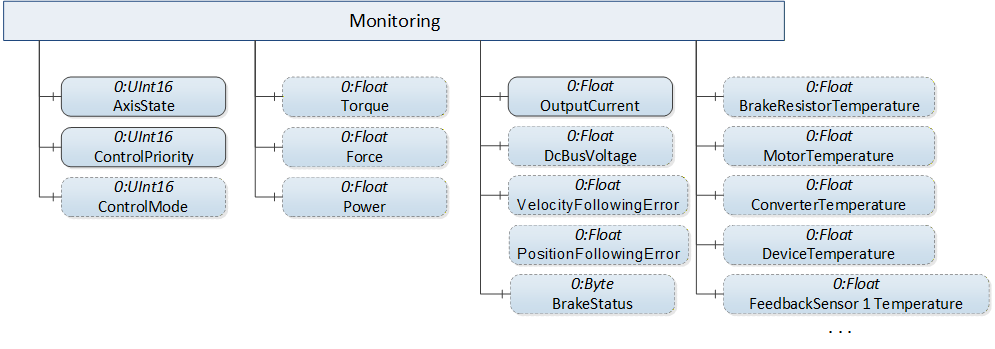
Monitoring folder in Actual and Command Values sub-aspect
The Monitoring folder contains Monitoring Variables describing measurements of the Axis/DO which are of interest for monitoring (see derived Axis/DO ObjectTypes and Table 33) encoded as numeric data type. If the corresponding Standard Signal is configured and its representation is provided in the PNSignals folder, the Monitoring Variable shall be linked to the Signal Variable using a 0:RepresentsSameEntityAs ReferenceType.
Figure 13 Shows the possible components of the "Monitoring" folder common for all derived Axis Object types, as described in Table 16.
The AxisState Variable contains the actual state of the Axis/DO internal state machine modelled as 0:MultiStateDiscreteType defined in [OPC 10000-8].
The ControlPriority Variable contains the leading control context (PROFIBUS, PROFINET, setup tool, …) of the Axis/DO also modelled as 0:MultiStateDiscreteType.
The ControlMode Variable contains the currently active control function in the overall control cascade modelled as 0:MultiStateDiscreteType.
The content of the EnumStrings lookup table Property is defined in Table 17 for all these 0:MultiStateDiscreteType Variables. The "Locale" field of the 0:LocalizedText structures is Server specific.
For a description of all Variables and Properties in the "Monitoring" folder see Table 33.
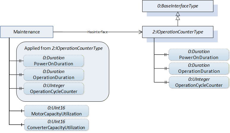
Maintenance folder in Axis Properties sub-aspect
The Maintenance folder contains optional properties defined by the 2:IOperationCounterType Interface specified in [OPC 10000-100] as well as parameters yielding capacity related information. Figure 14 shows the possible components of the "Maintenance" folder common for all derived Axis Object types, as described in Table 16.
For a description of the Variables and Properties in the "Maintenance" folder see Table 33.
LimitSupervision folder in Axis Properties sub-aspect
The LimitSupervision folder contains Variables with Values describing limit values for motor current, torque, and the like. These limit Variables differ between concrete derived Axis ObjectTypes and are specified separately for each derived Axis ObjectType.
For a description of the Variables in the "LimitSupervision" folder see Table 33.
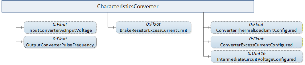
CharacteristicsConverter folder in Axis Properties sub-aspect
The CharacteristicsConverter folder contains Variables with Values describing key data of the Drive's converter. Figure 15 shows the possible components of the "CharacteristicsConverter" folder common for all derived Axis Object types, as described in Table 16.
For a description of the Variables in the "CharacteristicsConverter" folder see Table 33.
CharacteristicsMotorAndControl folder in Axis Properties sub-aspect
The CharacteristicsMotorAndControl folder contains Variables with Values describing key data of the Drive's motor and its key control features. Figure 16 shows the possible components of the "CharacteristicsMotorAndControl" folder common for all derived Axis Object types, as described in Table 16.
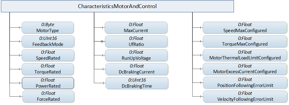
The FeedbackMode Variable shall contain the Value "FEEDBACK_SENSOR_1" if only one sensing device is present, which is the motor sensor in this case.
For a description of the Variables in the "CharacteristicsMotorAndControl" folder see Table 33.
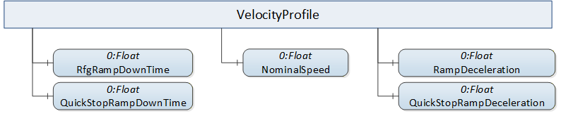
VelocityProfile folder in Axis Properties sub-aspect
The VelocityProfile folder contains Variables describing key properties of brake ramps. The folder contains the properties mandatory for each derived Axis Object types. Figure 17 shows the components of the "VelocityProfile" folder common for all derived Axis Object types, as described in Table 16.
Diagnosis sub-aspect
The 3:LogbookType Object defined in [OPC 30143 ENC] provides Methods for accessing the Drive's fault buffer (see [PI 3172 PDP] Fault Buffer Mechanism). These Methods can be used by Clients to obtain the active diagnosis entries (that is, get all fault entries without "Event going" timestamp) or apply custom filter criteria (see [OPC 30143 ENC] chapter 7.5 LogbookType for details). In conjunction with establishing a Subscription for one of the supported EventTypes of the 3:LogbookType Object Clients can synchronize themselves with the current diagnosis status and will receive Notifications for each change of the diagnosis status subsequently, such as coming, going and the like. The possible values for the EventCode are defined in [PI 3172 PDP], see Table 57.
The Server might provide DiagnosisAlarmType Events and / or 3:LogbookEventType Events.
Safety Object in Actual and Command Values sub-aspect
The optional SafetyType Object has SafetyFunctionType Object components describing safety functions. For each available safety function, basic settings regarding selection and activation status are provided (see 7.8 and 7.9).
7.2 VelocityDriveAxisType
The VelocityDriveAxisType is an DriveAxisType with a speed command interface. Figure 18 shows a block diagram demonstrating the basic organization and control flow for this axis type. If the Drive is a PROFIdrive the VelocityDriveAxisType is used to represent AC1 Drive Objects using a speed command interface.
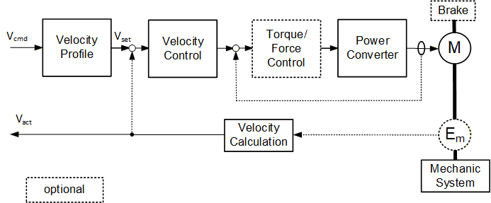
Figure 19 shows the components added by the VelocityDriveAxisType ObjectType to the DriveAxisType it is derived from.
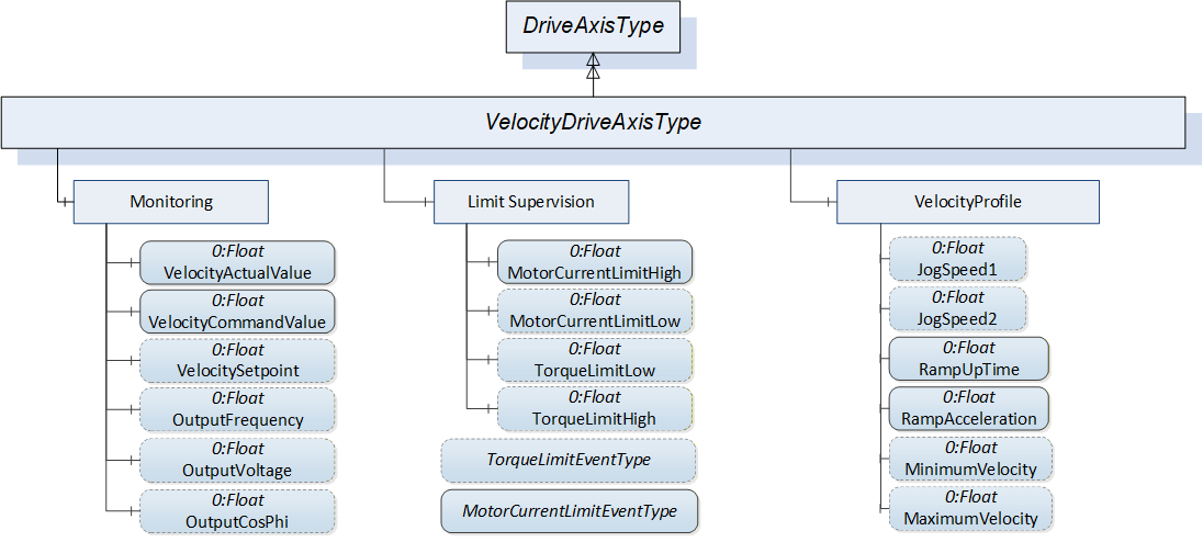
The formal definition of the VelocityDriveAxisType ObjectType can be found in Table 18.
| Attribute | Value | ||||
| BrowseName | VelocityDriveAxisType | ||||
| IsAbstract | False | ||||
| References | Node Class | BrowseName | DataType | TypeDefinition | Other |
|---|---|---|---|---|---|
| Subtype of the DriveAxisType. | |||||
| 0:GeneratesEvent | ObjectType | TorqueLimitEventType | |||
| 0:GeneratesEvent | ObjectType | MotorCurrentLimitEventType | |||
| Conformance Units | |||||
|---|---|---|---|---|---|
| PDRV Measurement | |||||
The components of the VelocityDriveAxisType have additional subcomponents which are defined in Table 19.
| BrowsePath | References | NodeClass | BrowseName | DataType | TypeDefinition | Others |
| Monitoring | 0:HasComponent | Variable | VelocitySetpoint | 0:Float | 0:AnalogUnitType | M, RO |
| Monitoring | 0:HasComponent | Variable | VelocityCommandValue | 0:Float | 0:AnalogUnitType | M, RO |
| Monitoring | 0:HasComponent | Variable | VelocityActualValue | 0:Float | 0:AnalogUnitType | M, RO |
| Monitoring | 0:HasComponent | Variable | OutputFrequency | 0:Float | 0:AnalogUnitType | O, RO |
| Monitoring | 0:HasComponent | Variable | OutputVoltage | 0:Float | 0:AnalogUnitType | O, RO |
| Monitoring | 0:HasComponent | Variable | OutputCosPhi | 0:Float | 0:BaseAnalogType | O, RO |
| LimitSupervision | 0:HasComponent | Variable | MotorCurrentLimitHigh | 0:Float | 0:AnalogUnitType | O, RO |
| LimitSupervision | 0:HasComponent | Variable | MotorCurrentLimitLow | 0:Float | 0:AnalogUnitType | O, RO |
| LimitSupervision | 0:HasComponent | Variable | TorqueLimitLow | 0:Float | 0:AnalogUnitType | O, RO |
| LimitSupervision | 0:HasComponent | Variable | TorqueLimitHigh | 0:Float | 0:AnalogUnitType | O, RO |
| VelocityProfile | 0:HasComponent | Variable | JogSpeed1 | 0:Float | 0:AnalogUnitType | O, RO |
| VelocityProfile | 0:HasComponent | Variable | JogSpeed2 | 0:Float | 0:AnalogUnitType | O, RO |
| VelocityProfile | 0:HasComponent | Variable | RfgRampUpTime | 0:Float | 0:BaseAnalogType | M, RO |
| VelocityProfile | 0:HasComponent | Variable | RfgAcceleration | 0:Float | 0:AnalogUnitType | M, RO |
| VelocityProfile | 0:HasComponent | Variable | MinimumVelocity | 0:Float | 0:AnalogUnitType | O, RO |
| VelocityProfile | 0:HasComponent | Variable | MaximumVelocity | 0:Float | 0:AnalogUnitType | O, RO |
7.3 FrequencyDriveAxisType
A FrequencyDriveAxisType is a DriveAxisType with a frequency command interface. Figure 20 shows a block diagram demonstrating the basic organization and control flow for this axis type. If the Drive is a PROFIdrive, the FrequencyDriveAxisType is used to represent AC1 Drive Objects using a frequency command interface.
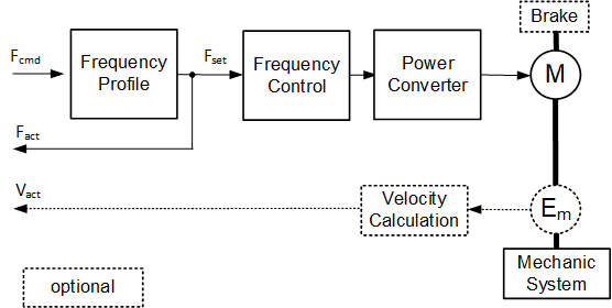
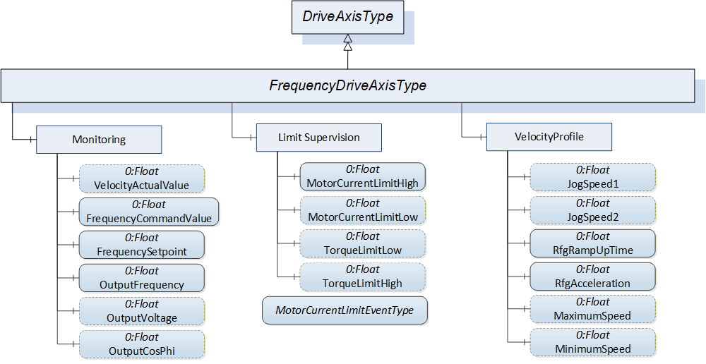
Figure 21 shows the components added by the FrequencyDriveAxisType ObjectType to the DriveAxisType it is derived from.
The formal definition of the FrequencyDriveAxisType ObjectType can be found in Table 20.
| Attribute | Value | ||||
| BrowseName | FrequencyDriveAxisType | ||||
| IsAbstract | False | ||||
| References | Node Class | BrowseName | DataType | TypeDefinition | Other |
|---|---|---|---|---|---|
| Subtype of the DriveAxisType. | |||||
| 0:GeneratesEvent | ObjectType | MotorCurrentLimitEventType | |||
| Conformance Units | |||||
|---|---|---|---|---|---|
| PDRV Measurement | |||||
The components of the FrequencyDriveAxisType have additional subcomponents which are defined in Table 21.
| BrowsePath | References | NodeClass | BrowseName | DataType | TypeDefinition | Others |
| Monitoring | 0:HasComponent | Variable | FrequencyCommandValue | 0:Float | 0:AnalogUnitType | M, RO |
| Monitoring | 0:HasComponent | Variable | VelocityActualValue | 0:Float | 0:AnalogUnitType | O, RO |
| Monitoring | 0:HasComponent | Variable | FrequencySetpoint | 0:Float | 0:AnalogUnitType | M, RO |
| Monitoring | 0:HasComponent | Variable | OutputFrequency | 0:Float | 0:AnalogUnitType | M, RO |
| Monitoring | 0:HasComponent | Variable | OutputVoltage | 0:Float | 0:AnalogUnitType | O, RO |
| Monitoring | 0:HasComponent | Variable | OutputCosPhi | 0:Float | 0:BaseAnalogType | O, RO |
| LimitSupervision | 0:HasComponent | Variable | MotorCurrentLimitHigh | 0:Float | 0:AnalogUnitType | M, RO |
| LimitSupervision | 0:HasComponent | Variable | MotorCurrentLimitLow | 0:Float | 0:AnalogUnitType | O, RO |
| LimitSupervision | 0:HasComponent | Variable | TorqueLimitLow | 0:Float | 0:AnalogUnitType | O, RO |
| LimitSupervision | 0:HasComponent | Variable | TorqueLimitHigh | 0:Float | 0:AnalogUnitType | O, RO |
| VelocityProfile | 0:HasComponent | Variable | JogSpeed1 | 0:Float | 0:AnalogUnitType | O, RO |
| VelocityProfile | 0:HasComponent | Variable | JogSpeed2 | 0:Float | 0:AnalogUnitType | O, RO |
| VelocityProfile | 0:HasComponent | Variable | RfgRampUpTime | 0:Float | 0:AnalogUnitType | M, RO |
| VelocityProfile | 0:HasComponent | Variable | RfgAcceleration | 0:Float | 0:AnalogUnitType | M, RO |
| VelocityProfile | 0:HasComponent | Variable | MinimumVelocity | 0:Float | 0:AnalogUnitType | O, RO |
| VelocityProfile | 0:HasComponent | Variable | MaximumVelocity | 0:Float | 0:AnalogUnitType | O, RO |
7.4 PositioningDriveAxisType
A PositioningDriveAxisType is an DriveAxisType with a motion trajectory command interface. Figure 22 shows a block diagram demonstrating the basic organization and control flow for this axis type. If the Drive is a PROFIdrive the PositioningDriveAxisType is used to represent AC3 Drive Objects using a motion trajectory command interface (program submode or MDI submode).
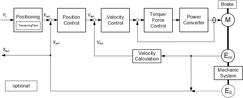
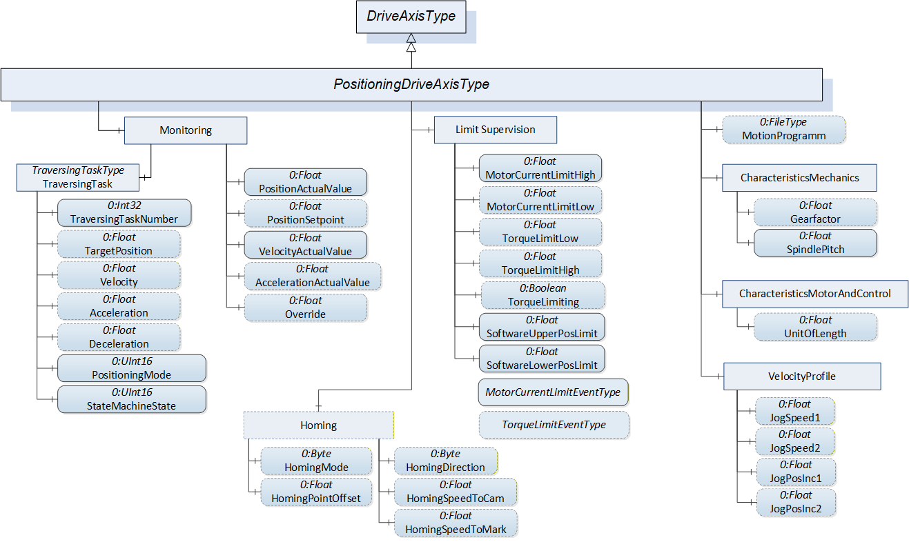
Figure 23 shows the components added by the PositioningDriveAxisType ObjectType to the DriveAxisType it is derived from.
The formal definition of the PositioningDriveAxisType ObjectType can be found in Table 22.
| Attribute | Value | ||||
| BrowseName | PositioningDriveAxisType | ||||
| IsAbstract | False | ||||
| References | Node Class | BrowseName | DataType | TypeDefinition | Other |
|---|---|---|---|---|---|
| Subtype of the DriveAxisType. | |||||
| 0:HasComponent | Object | Homing | 0:FolderType | O | |
| 0:HasComponent | Object | CharacteristicsMechanics | 0:FolderType | M | |
| 0:HasComponent | Object | LimitSupervision | 0:FolderType | M | |
| 0:HasComponent | Object | MotionProgram | 0:FileType | O | |
| 0:GeneratesEvent | ObjectType | TorqueLimitEventType | |||
| 0:GeneratesEvent | ObjectType | MotorCurrentLimitEventType | |||
| Conformance Units | |||||
|---|---|---|---|---|---|
| PDRV Measurement | |||||
Some components of the PositioningDriveAxisType have additional subcomponents which are defined in Table 23.
| BrowsePath | References | NodeClass | BrowseName | DataType | TypeDefinition | Others |
| Monitoring | 0:HasComponent | Variable | PositionActualValue | 0:Float | 0:AnalogUnitType | M, RO |
| Monitoring | 0:HasComponent | Variable | PositionSetpoint | 0:Float | 0:AnalogUnitType | O, RO |
| Monitoring | 0:HasComponent | Variable | VelocityActualValue | 0:Float | 0:AnalogUnitType | M, RO |
| Monitoring | 0:HasComponent | Variable | AccelerationActualValue | 0:Float | 0:AnalogUnitType | O, RO |
| Monitoring | 0:HasComponent | Object | TraversingTask | TraversingTaskType | M | |
| Monitoring | 0:HasComponent | Variable | Override | 0:Float | 0:BaseDataVariableType | O, RO |
| VelocityProfile | 0:HasComponent | Variable | JogSpeed1 | 0:Float | 0:AnalogUnitType | O, RO |
| VelocityProfile | 0:HasComponent | Variable | JogSpeed2 | 0:Float | 0:AnalogUnitType | O, RO |
| VelocityProfile | 0:HasComponent | Variable | JogPosInc1 | 0:Float | 0:AnalogUnitType | O, RO |
| VelocityProfile | 0:HasComponent | Variable | JogPosInc2 | 0:Float | 0:AnalogUnitType | O, RO |
| LimitSupervision | 0:HasComponent | Variable | MotorCurrentLimitHigh | 0:Float | 0:AnalogUnitType | M, RO |
| LimitSupervision | 0:HasComponent | Variable | MotorCurrentLimitLow | 0:Float | 0:AnalogUnitType | O, RO |
| LimitSupervision | 0:HasComponent | Variable | TorqueLimitLow | 0:Float | 0:AnalogUnitType | O, RO |
| LimitSupervision | 0:HasComponent | Variable | TorqueLimitHigh | 0:Float | 0:AnalogUnitType | O, RO |
| LimitSupervision | 0:HasComponent | Variable | SoftwareUpperPosLimit | 0:Float | 0:AnalogUnitType | M, RO |
| LimitSupervision | 0:HasComponent | Variable | SoftwareLowerPosLimit | 0:Float | 0:AnalogUnitType | M, RO |
| LimitSupervision | 0:HasComponent | Variable | TorqueLimiting | 0:Boolean | 0:BaseDataVariableType | O, RO |
| CharacteristicsMechanics | 0:HasComponent | Variable | Gearfactor | 0:Float | 0:AnalogUnitType | O, RO |
| CharacteristicsMechanics | 0:HasComponent | Variable | SpindlePitch | 0:Float | 0:AnalogUnitType | O, RO |
| CharacteristicsMotorAndControl | 0:HasComponent | Variable | UnitOfLength | 0:Float | 0:AnalogUnitType | O, RO |
| Homing | 0:HasComponent | Variable | HomingDirection | 0:Byte | HomingDirectionType | O, RO |
| Homing | 0:HasComponent | Variable | HomingSpeedToCam | 0:Float | 0:AnalogUnitType | O, RO |
| Homing | 0:HasComponent | Variable | HomingSpeedToMark | 0:Float | 0:AnalogUnitType | O, RO |
| Homing | 0:HasComponent | Variable | HomingPointOffset | 0:Float | 0:AnalogUnitType | O, RO |
| Homing | 0:HasComponent | Variable | HomingMode | 0:Byte | HomingModeType | O, RO |
7.5 VelocityServoDriveAxisType
A VelocityServoDriveAxisType is an DriveAxisType with a velocity command interface. Figure 24 shows a block diagram demonstrating the basic organization and control flow for this axis type. If the Drive is a PROFIdrive, the VelocityServoDriveAxisType is used to represent AC4 Drive Objects using a speed command interface.
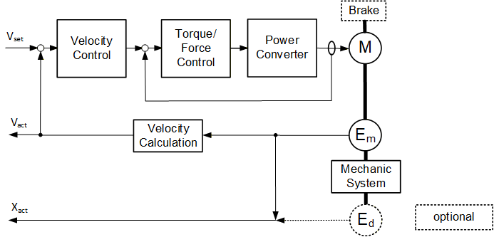
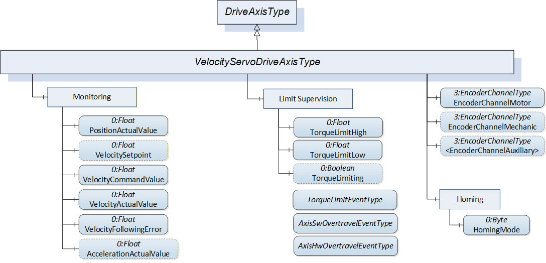
Figure 25 shows the components added by the VelocityServoDriveAxisType ObjectType to the DriveAxisType it is derived from.
The formal definition of the VelocityServoDriveAxisType ObjectType can be found in Table 24.
| Attribute | Value | ||||
| BrowseName | VelocityServoDriveAxisType | ||||
| IsAbstract | False | ||||
| References | Node Class | BrowseName | DataType | TypeDefinition | Other |
|---|---|---|---|---|---|
| Subtype of the DriveAxisType. | |||||
| 0:HasComponent | Object | EncoderChannelMotor | 3:EncoderChannelType | M | |
| 0:HasComponent | Object | EncoderChannelMechanic | 3:EncoderChannelType | O | |
| 0:HasComponent | Object | <EncoderChannelAuxiliary> | 3:EncoderChannelType | OP | |
| 0:HasComponent | Object | Homing | 0:FolderType | M | |
| 0:GeneratesEvent | ObjectType | AxisSwOvertravelEventType | |||
| 0:GeneratesEvent | ObjectType | AxisHwOvertravelEventType | |||
| 0:GeneratesEvent | ObjectType | TorqueLimitEventType | |||
| Conformance Units | |||||
|---|---|---|---|---|---|
| PDRV Measurement | |||||
Some components of the VelocityServoDriveAxisType have additional subcomponents which are defined in Table 25.
| BrowsePath | References | NodeClass | BrowseName | DataType | TypeDefinition | Others |
| Monitoring | 0:HasComponent | Variable | VelocitySetpoint | 0:Float | 0:AnalogUnitType | O, RO |
| Monitoring | 0:HasComponent | Variable | VelocityCommandValue | 0:Float | 0:AnalogUnitType | M, RO |
| Monitoring | 0:HasComponent | Variable | VelocityActualValue | 0:Float | 0:AnalogUnitType | M, RO |
| Monitoring | 0:HasComponent | Variable | AccelerationActualValue | 0:Float | 0:AnalogUnitType | O, RO |
| Homing | 0:HasComponent | Variable | HomingMode | 0:Byte | HomingModeType | M, RO |
| LimitSupervision | 0:HasComponent | Variable | TorqueLimitHigh | 0:Float | 0:AnalogUnitType | M, RO |
| LimitSupervision | 0:HasComponent | Variable | TorqueLimitLow | 0:Float | 0:AnalogUnitType | M, RO |
| LimitSupervision | 0:HasComponent | Variable | TorqueLimiting | 0:Boolean | 0:BaseDataVariableType | O, RO |
7.6 PositionServoDriveAxisType
A PositionServoDriveAxisType is an DriveAxisType with a position command interface. Figure 26 shows a block diagram demonstrating the basic organization and control flow for this axis type. If the Drive is a PROFIdrive the PositionServoDriveAxisType is used to represent AC5 Drive Objects.
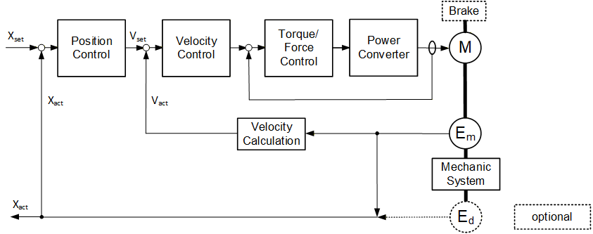
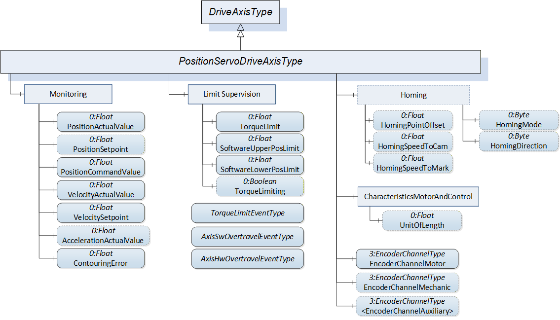
Figure 27 shows the components added by the PositionServoDriveAxisType ObjectType to the DriveAxisType it is derived from.
The formal definition of the PositionServoDriveAxisType ObjectType can be found in Table 26.
| Attribute | Value | ||||
| BrowseName | PositionServoDriveAxisType | ||||
| IsAbstract | False | ||||
| References | Node Class | BrowseName | DataType | TypeDefinition | Other |
|---|---|---|---|---|---|
| Subtype of the DriveAxisType. | |||||
| 0:HasComponent | Object | EncoderChannelMotor | 3:EncoderChannelType | M | |
| 0:HasComponent | Object | EncoderChannelMechanic | 3:EncoderChannelType | O | |
| 0:HasComponent | Object | <EncoderChannelAuxiliary> | 3:EncoderChannelType | OP | |
| 0:HasComponent | Object | Homing | 0:FolderType | O | |
| 0:GeneratesEvent | ObjectType | AxisSwOvertravelEventType | |||
| 0:GeneratesEvent | ObjectType | AxisHwOvertravelEventType | |||
| 0:GeneratesEvent | ObjectType | TorqueLimitEventType | |||
| Conformance Units | |||||
|---|---|---|---|---|---|
| PDRV Measurement | |||||
Some components of the PositionServoDriveAxisType have additional subcomponents which are defined in Table 27.
| BrowsePath | References | NodeClass | BrowseName | DataType | TypeDefinition | Others |
| Monitoring | 0:HasComponent | Variable | PositionCommandValue | 0:Float | 0:AnalogUnitType | M, RO |
| Monitoring | 0:HasComponent | Variable | VelocitySetpoint | 0:Float | 0:AnalogUnitType | M, RO |
| Monitoring | 0:HasComponent | Variable | PositionActualValue | 0:Float | 0:AnalogUnitType | M, RO |
| Monitoring | 0:HasComponent | Variable | VelocityActualValue | 0:Float | 0:AnalogUnitType | M, RO |
| Monitoring | 0:HasComponent | Variable | PositionSetpoint | 0:Float | 0:AnalogUnitType | O, RO |
| Monitoring | 0:HasComponent | Variable | AccelerationActualValue | 0:Float | 0:AnalogUnitType | O, RO |
| Monitoring | 0:HasComponent | Variable | ContouringError | 0:Float | 0:AnalogUnitType | M, RO |
| LimitSupervision | 0:HasComponent | Variable | TorqueLimit | 0:Float | 0:AnalogUnitType | M, RO |
| LimitSupervision | 0:HasComponent | Variable | SoftwareUpperPosLimit | 0:Float | 0:AnalogUnitType | M, RO |
| LimitSupervision | 0:HasComponent | Variable | SoftwareLowerPosLimit | 0:Float | 0:AnalogUnitType | M, RO |
| LimitSupervision | 0:HasComponent | Variable | TorqueLimiting | 0:Boolean | 0:BaseDataVariableType | O, RO |
| CharacteristicsMotorAndControl | 0:HasComponent | Variable | UnitOfLength | 0:Float | 0:AnalogUnitType | O, RO |
| Homing | 0:HasComponent | Variable | HomingDirection | 0:Byte | HomingDirectionType | O, RO |
| Homing | 0:HasComponent | Variable | HomingSpeedToCam | 0:Float | 0:AnalogUnitType | O, RO |
| Homing | 0:HasComponent | Variable | HomingSpeedToMark | 0:Float | 0:AnalogUnitType | O, RO |
| Homing | 0:HasComponent | Variable | HomingPointOffset | 0:Float | 0:AnalogUnitType | O, RO |
| Homing | 0:HasComponent | Variable | HomingMode | 0:Byte | HomingModeType | O, RO |
7.7 TraversingTaskType
The TraversingTaskType represents a traversing task.
| Attribute | Value | ||||
| BrowseName | TraversingTaskType | ||||
| IsAbstract | False | ||||
| References | Node Class | BrowseName | DataType | TypeDefinition | Other |
|---|---|---|---|---|---|
| Subtype of the 0:BaseObjectType defined in [OPC 10000-5]. | |||||
| 0:HasComponent | Variable | TraversingTaskNumber | 0:Int32 | 0:BaseDataVariableType | M, RO |
| 0:HasComponent | Variable | TargetPosition | 0:Float | 0:AnalogUnitType | O, RO |
| 0:HasComponent | Variable | Velocity | 0:Float | 0:AnalogUnitType | O, RO |
| 0:HasComponent | Variable | Acceleration | 0:Float | 0:AnalogUnitType | O, RO |
| 0:HasComponent | Variable | Deceleration | 0:Float | 0:AnalogUnitType | O, RO |
| 0:HasComponent | Variable | PositioningMode | 0:UInt16 | 0:MultiStateDiscreteType | M, RO |
| Conformance Units | |||||
|---|---|---|---|---|---|
| PDRV Measurement | |||||
The TraversingTaskNumber Variable contains the number of the traversing task currently executed. Interpretation of TraversingTaskNumber:
| TraversingTaskNumber Value | Traversing task executed |
| -5 | Jogging positive (S42) |
| -4 | Jogging negative (S42) |
| -3 | Homing procedure (S44) |
| -2 | MDI sub-mode active |
| -1 | No traversing task is executed: stand still (S41) |
| >=0 | Number of traversing task (0 - 1023) |
If no traversing task is executed (TraversingTaskNumber == -1), the Value of all other Variables shall be 0. If a traversing task is executed (TraversingTaskNumber >=0), the AxisState Variable contains one of the values belonging to the S45 sub state machine (see [PI 3172 PDP], Figure 35 also).
The TargetPosition Variable contains the target position for the traversing task generator.
The Velocity Variable contains the desired speed for the traversing task generator.
The Acceleration Variable contains the desired acceleration for the traversing task generator.
The PositioningMode Variable contains the information if the TargetPosition Variable has to be interpreted as absolute or relative position encoded as 0:MultiStateDiscreteType defined in [OPC 10000-8]. The StateMachineState Variable contains the state of the positioning mode substate machine also encoded as 0:MultiStateDiscreteType. The content of their EnumStrings lookup table Properties is defined in Table 29.
| BrowsePath | Value Attribute | ||
| INACTIVE RELATIVE_POSITIONING ABSOLUTE_SHORTEST_PATH_MODULO_DIRECTION _POSITIONING ABSOLUTE_POSITIVE_MODULO_DIRECTION _POSITIONING ABSOLUTE_NEGATIVE_ MODULO_DIRECTION _POSITIONING |
The following table contains descriptions of the semantic for all possible Values of the PositioningMode Variable.
| Element Value | Description |
| INACTIVE | No traversing task is active. |
| RELATIVE_POSITIONING | Relative Positioning. |
| ABSOLUTE_SHORTEST_PATH_MODULO_DIRECTION _POSITIONING | The absolute position shall be reached by the shortest path. |
| ABSOLUTE_POSITIVE_MODULO_DIRECTION _POSITIONING | The absolute position shall be reached by a motion in positive direction. |
| ABSOLUTE_NEGATIVE_ MODULO_DIRECTION _POSITIONING | The absolute position shall be reached by a motion in negative direction. |
7.8 SafetyType
The SafetyType contains SafetyFunctionType Variables describing basic settings for safety functions.
| Attribute | Value | ||||
| BrowseName | SafetyType | ||||
| IsAbstract | False | ||||
| References | Node Class | BrowseName | DataType | TypeDefinition | Other |
|---|---|---|---|---|---|
| Subtype of the 0:BaseObjectType defined in [OPC 10000-5]. | |||||
| 0:HasComponent | Object | STO | SafetyFunctionType | M | |
| 0:HasComponent | Object | SS1 | SafetyFunctionType | O | |
| 0:HasComponent | Object | SS2 | SafetyFunctionType | O | |
| 0:HasComponent | Object | SOS | SafetyFunctionType | O | |
| 0:HasComponent | Object | SLS | SafetyFunctionType | O | |
| 0:HasComponent | Object | SDI | SafetyFunctionType | O | |
| 0:HasComponent | Object | SLA | SafetyFunctionType | O | |
| 0:HasComponent | Object | SLP | SafetyFunctionType | O | |
| Conformance Units | |||||
|---|---|---|---|---|---|
| PDRV Measurement | |||||
The STO Object represents the status of the "Safe torque off" safety function.
The SS1 Object represents the status of the "Safe stop 1" safety function.
The SS2 Object represents the status of the "Safe stop 2" safety function.
The SOS Object represents the status of the "Safe operating stop" safety function.
The SLS Object represents the status of the "Safely limited speed" safety function.
The SDI Object represents the status of the "Safe direction" safety function.
The SLA Object represents the status of the "Safely limited acceleration" safety function.
The SLP Object represents the status of the "Safely limited position" safety function.
If a specific safety function is supported by the Axis/DO, the representing SafetyFunctionType Object shall be provided.
7.9 SafetyFunctionType
The SafetyFunctionType represents the status of one safety function.
| Attribute | Value | ||||
| BrowseName | SafetyFunctionType | ||||
| IsAbstract | False | ||||
| References | Node Class | BrowseName | DataType | TypeDefinition | Other |
|---|---|---|---|---|---|
| Subtype of the 0:BaseObjectType defined in [OPC 10000-5]. | |||||
| 0:HasComponent | Variable | SelectionState | 0:UInt16 | 0:MultiStateDiscreteType | M |
| 0:HasComponent | Variable | ActivationState | 0:UInt16 | 0:MultiStateDiscreteType | M |
| 0:HasProperty | Variable | Limit | 0:Float | 0:PropertyType | O |
The SelectionState Variable represents the selection status of the represented safety function.
The ActivationState Variable represents the activation status of the represented safety function.
The Limit Variable represents the speed limit if representing the SLS safety function or the acceleration limit if representing the SLA safety function. Shall only be provided for these two safety functions.
| BrowsePath | Value Attribute | ||
| NONE SELECTED SELECTED_INTERN SELECTED_EXTERN SELECTED_LIMIT_1 SELECTED_LIMIT_2 SELECTED_LIMIT_3 SELECTED_LIMIT_4 SELECTED_POS SELECTED_NEG | ||
| NONE POWER_REMOVED SS1_ACTIVE SS1_ACTIVE_FAULTED SS2_ACTIVE SS2_ACTIVE_FAULTED SOS_ACTIVE SOS_ACTIVE_FAULTED SLS_ACTIVE SLS_ACTIVE_FAULTED SDI_POS_ACTIVE SDI_NEG_ACTIVE SLA_ACTIVE SLA_ACTIVE_FAULTED SLP_ACTIVE SLP_ACTIVE_FAULTED SLP_INOPERABLE |
7.10 OPC UA Variable Mapping to Drive Properties
Table 33 lists the OPC UA Variables and the drive properties represented by those Variables which are components of the drive ObjectTypes above.
The Variables listed are components of a parent folder which belongs to the Axis Object. The parent folder is specified in the row preceding the rows specifying the Variables which belong to this very folder.
| BrowseName | Drive Property represented |
| Monitoring | |
| AxisState | Actual state of the Axis/DO' internal state machine, e.g. S2, encoded as 0:MultiStateDiscreteType. The content of the EnumStrings lookup table Property is defined in Table 17. |
| ControlPriority | Leading control context, e.g. PROFIBUS or PROFINET, of the Axis/DO encoded as 0:MultiStateDiscreteType. The content of the EnumStrings lookup table Property is defined in Table 17. |
| ControlMode | Active control function in the overall control cascade, e.g. SPEED_CONTROL_MODE, encoded as 0:MultiStateDiscreteType. The content of the EnumStrings lookup table Property is defined in Table 17. |
| VelocityCommandValue | Commanded velocity of the controller, transmitted by the associated Telegram Signal. |
| VelocitySetpoint | Velocity setpoint as input for motor/axis control unit. |
| VelocityActualValue | Current velocity. |
| PositionCommandValue | Commanded position of the controller. |
| PositionSetpoint | Setpoint as input for motor/axis control unit. |
| PositionActualValue | Current position of motor or axis. |
| FrequencyCommandValue | Commanded frequency of the controller, transmitted by the associated Telegram Signal. |
| FrequencySetpoint | Frequency setpoint as input for motor/axis control unit. |
| AccelerationActualValue | Current acceleration of motor or axis. |
| OutputFrequency | Output frequency of the Axis/DO. |
| OutputVoltage | Output voltage of the Axis/DO. |
| OutputCosPhi | Actual motor power factor. |
| OutputCurrent | Actual output current measured at the clamp. |
| Torque | Actual axis torque. Provide for rotatory axis only. |
| Force | Actual axis force. Provide for linear axis only. |
| Power | Actual power consumption. |
| MotorTemperature | Actual motor temperature. |
| ConverterTemperature | Actual converter temperature. |
| DeviceTemperature | Actual device temperature. |
| <FeedbackSensor1..3Temperature> | Actual temperature of feedback sensor. |
| BrakeResistorTemperature | Actual temperature of brake resistor. |
| DcBusVoltage | Actual decent bus voltage value. |
| PositionFollowingError | Actual difference between PositionSetpoint and PositionActualValue. |
| VelocityFollowingError | Actual difference between VelocitySetpoint and VelocityActualValue. |
| BrakeStatus | Actual brake status encoded as 0:MultiStateDiscreteType. The content of the EnumStrings lookup table Property is defined in Table 34. The Variable shall not be provided if the Drive Axis has no brake. |
| ContouringError | Limit of contouring error supervision. |
| Override | Active override factor on programmed velocity in percent (100% == programmed velocity). |
| Maintenance | |
|---|---|
| PowerOnDuration | Actual duration of the power-on-state in milliseconds of the Axis/DO. |
| OperationDuration | Actual duration of performing effective operation of the Axis/DO (e.g. the Drive's motor "works") in milliseconds. |
| OperationCycleCounter | Number of switches between power-on and operation. |
| MotorCapacityUtilization | Utilization of motor thermal capacity, in % of motor load limit (0% - 100%). |
| ConverterCapacityUtilization | Utilization of converter thermal capacity, in % of converter load limit (0% - 100%). |
| CharacteristicsConverter | |
|---|---|
| InputConverterAcInputVoltage | Input alternating voltage. |
| OutputConverterPulseFrequency | Pulse frequency of the drive's converter. |
| IntermediateCircuitVoltageConfigured | Voltage of intermediate circuit determined by configuration data. |
| ConverterThermalLoadLimitConfigured | Thermal load limit of converter determined by configuration data. |
| ConverterExcessCurrentConfigured | Excess current of converter determined by configuration data. |
| BrakeResistorExcessCurrentLimit | Excess current limit of brake resistor, in ampere. |
| CharacteristicsMotorAndControl | |
|---|---|
| PowerRated | Rated power of the motor. |
| SpeedRated | Rated speed of rotatory motor. If the motor of the axis does not work rotatory, the Variable shall not be provided. |
| TorqueRated | Rated torque of the motor. |
| ForceRated | Rated force of a linear moving axis. |
| MaxCurrent | Maximum current the motor draws from the power supply. |
| UfRatio | Constant ratio of voltage and frequency. |
| RunUpVoltage | Voltage the motor creates at the feeder clamp during start-up. |
| DcBrakingCurrent | Current the motor draws during braking. |
| DcBrakingTime | Time needed in dc-braking mode until stand still if the braking current given by the DcBrakingCurrent Variable is applied |
| FeedbackMode | Sensing device used by closed loop control of the Axis/DO, e.g. FEEDBACK_SENSOR_1, encoded as 0:MultiStateDiscreteType. The content of the EnumStrings lookup table Property is defined in Table 17. |
| SpeedMaxConfigured | Maximum speed determined by configuration data. |
| TorqueMaxConfigured | Maximum torque determined by configuration data. |
| MotorThermalLoadLimitConfigured | Thermal load limit of motor determined by configuration data. |
| MotorExcessCurrentConfigured | Excess current of motor determined by configuration data. |
| MotorType | Kind of motor, e.g. STEPPER, INDUCTION_ROTATORY, etc. encoded as 0:MultiStateDiscreteType. The content of the EnumStrings lookup table Property is defined in Table 17. |
| PositionFollowingErrorLimit | Maximum allowed position deviation in the position closed loop control. Exceeding this limit causes position following error. |
| VelocityFollowingErrorLimit | Maximum allowed velocity deviation in the velocity closed loop control. Exceeding this limit causes velocity following error. |
| UnitOfLength | Internal setting of length unit. The length unit is used for transmitting position, velocity, acceleration, deceleration in the PROFIdrive standard telegram 9. This Variable should be provided for the application classes 3 and 5 if the Signals sub-aspect is provided. |
| LimitSupervision | |
|---|---|
| MotorCurrentLimitHigh | Current upper velocity limit of the Axis/DO. |
| MotorCurrentLimitLow | Current lower velocity limit of the Axis/DO. |
| TorqueLimit | Torque limit of the motor. |
| TorqueLimitLow | Lower torque limit of the motor. |
| TorqueLimitHigh | Upper torque limit of the motor. |
| SoftwareUpperPosLimit | Software upper position limit. |
| SoftwareLowerPosLimit | Software lower position limit. |
| TorqueLimiting | Indicates if torque limiting is active. |
| VelocityProfile | |
|---|---|
| JogSpeed1 | Jogging setpoint 1 value (see [PDP], chapter 6.3.3.3.4). |
| JogSpeed2 | Jogging setpoint 2 value (see [PI 3172 PDP], chapter 6.3.3.3.4). |
| JogPosInc1 | Jogging position increment 1. |
| JogPosInc2 | Jogging position increment 2. |
| NominalSpeed | Reference value for ramp up (down) used to calculate ramp acceleration (deceleration) |
| RfgRampUpTime | Actual ramp up time of the Ramp Function Generator (RFG), see [PDP], chapter 6.3.3, in seconds |
| RfgRampDownTime | Actual ramp down time of the RFG (see RfgRampUpTime above), in seconds |
| QuickStopRampDownTime | Quick stop ramp down time, in seconds. |
| RfgAcceleration | Actual ramp acceleration. |
| RampDeceleration | Actual ramp deceleration. |
| QuickStopRampDeceleration | Quick stop ramp deceleration. |
| MinimumVelocity | Lowest speed of the ramp-function. |
| MaximumVelocity | Highest speed of the ramp-function. |
| CharacteristicsMechanics | |
|---|---|
| Gearfactor | Rotation to rotation transmission factor. |
| SpindlePitch | Rotation to linear transmission factor. |
| FollowingError | Limit of following error supervision. |
| Homing | |
|---|---|
| HomingDirection | Homing direction (POSITIVE or NEGATIVE) |
| HomingSpeedToCam | Speed when moving to cam. |
| HomingSpeedToMark | Speed when moving to mark. |
| HomingPointOffset | Home position shift for adjustment of axis mechanical zero. |
| HomingMode | Active homing mode (ABSOLUTE, REF_MARK, DIST_CODE, FLY). |
| Diagnosis | |
|---|---|
| Logbook | Representation of the Axis/DO fault buffer. |
| Element Index (==Value) | Element Value (locale "en") | Description |
| 0 | "NO_BRAKE" | No brake. |
| 1 | "OPEN_BRAKE" | Brake is open and has no effect. |
| 2 | "MECHANIC_BRAKE_APPLIED" | The mechanic brake is active. |
| 3 | "DC_BRAKE_APPLIED" | The DC brake is active. |
| 4 | "ROTOR_SHORT_APPLIED" | Rotor short circuit is active. |