
1 Scope
This part of the OPC UA FX specification series defines the general networking requirements for UAFX. This release includes definitions for functional networking requirements, including Bridge Component, End Station Component, IA-station, and UAFX Station, and network services, including remote management, topology discovery, and time synchronisation for Ethernet networks. Future releases will add additional requirements, including additional definitions for End Station Components and NETCONF-based remote management. Definitions for additional physical layer protocols such as SPE/APL, WLAN, or cellular, e.g., 5G, may also be added as required for the interoperable operation of UAFX in these networks.
UAFX intends for all networking-related configuration of End Station and Bridge Components to be done through NETCONF. Towards this goal, this release selects the basic protocol layers, NETCONF over TLS for remote management (see 7.2), as a first step. Moreover, LLDP YANG modules are selected for use with topology discovery (see 7.3). Future releases are planned to expand these configuration capabilities with the additional selection of NETCONF capabilities and YANG modules. Consequently, this release requires vendor-specific mechanisms such as web interfaces, CLI, and engineering tools to configure networking-related mechanisms and services.
A UAFX Station may implement a subset of the requirements defined in this document. OPC 10000-84 defines the OPC UA profiles that dictate which networking features, services, and capabilities need to be implemented to be compliant with a particular UAFX profile.
Definitions included in this document that are also covered by the IEC/IEEE 60802 TSN Profile for Industrial Automation will be superseded by the IEC/IEEE 60802 specification after that standard's publication, and this document will be updated accordingly.
2 Normative references
The following referenced documents are indispensable for the application of this OPC UA part. For dated references, only the edition cited applies. The latest edition of the referenced document (including any amendments and errata) applies for undated references.
OPC 10000‑1, OPC Unified Architecture - Part 1: Overview and Concepts
OPC 10000-1
OPC 10000‑4, OPC Unified Architecture - Part 4: Services
OPC 10000-4
OPC 10000‑5, OPC Unified Architecture - Part 5: Information Model
OPC 10000-5
OPC 10000‑12, OPC Unified Architecture - Part 12: Discovery and Global Services
OPC 10000-12
OPC 10000‑14, OPC Unified Architecture - Part 14: PubSub
OPC 10000-14
OPC 10000‑22, OPC Unified Architecture - Part 22: Base Network Model
OPC 10000-22
OPC 10000-80, OPC Unified Architecture - Part 80: UAFX Overview and Concepts
OPC 10000-80
OPC 10000‑81, OPC Unified Architecture - Part 81: UAFX Connecting Devices and Information Model
OPC 10000-81
IEEE Std 802‑2014, IEEE Standard for Local and Metropolitan Area Networks: Overview and Architecture
https://standards.ieee.org/standard/802-2014.html
IEEE Std 802.1AB‑2016, IEEE Standard for Local and Metropolitan Area Networks: Station and Media Access Control Connectivity Discovery
https://standards.ieee.org/standard/802_1AB-2016.html
IEEE Std 802.1AS‑2020, IEEE Standard for Local and Metropolitan Area Networks: Timing and Synchronisation for Time-Sensitive Applications
https://standards.ieee.org/standard/802_1AS-2020.html
IEEE Std 802.1Q‑2022, IEEE Standard for Local and Metropolitan Area Networks: Bridges and Bridged Networks
https://standards.ieee.org/standard/802_1Q-2022.html
IEEE Std 802.1Qcc‑2018, IEEE Standard for Local and Metropolitan Area Networks: Bridges and Bridged Networks - Amendment 31: Stream Reservation Protocol (SRP) Enhancements and Performance Improvements
https://standards.ieee.org/standard/802_1Qcc-2018.html
IEEE Std 802.1ABcu, IEEE Standard for Local and metropolitan area networks: Station and Media Access Control Connectivity Discovery - Amendment: YANG Data Model
https://standards.ieee.org/standard/802_1ABcu/
IEEE Std 802.3‑2018, IEEE Standard for Ethernet
https://standards.ieee.org/ieee/802.3/7071/
IETF RFC 7589, Using the NETCONF Protocol over Transport Layer Security (TLS) with Mutual X.509 Authentication, June 2015
https://www.rfc-editor.org/rfc/pdfrfc/rfc7589.txt.pdf
IETF RFC 2131- Dynamic Host Configuration Protocol, March 1997
https://www.rfc-editor.org/rfc/pdfrfc/rfc3246.txt.pdf
Internet Assigned Numbers Authority (IANA) On-line Database - Address Family Numbers
https://www.iana.org/assignments/address-family-numbers/address-family-numbers.xhtml
3 Terms, definitions, and abbreviated terms
3.1 Terms and definitions
For the purposes of this document, the terms and definitions given in OPC 10000‑4, OPC 10000-80, OPC 10000-100, IEEE Std 802‑2014, IEEE Std 802.1AS‑2020, IEEE Std 802.1AB‑2016, IEEE Std 802.1Q‑2022, IEEE Std 1588, as well as the following apply.
All used terms are italicised in this document as described in OPC 10000‑1.
3.1.1 Bridge
system that includes Media Access Control (MAC) Bridge or Virtual Local Area Network(VLAN) Bridge component functionality.
3.1.2 Bridge Component
set of Bridge functionalities necessary for acting as a traffic relay station in a network
3.1.3 device
independent physical entity capable of performing one or more specified functions in a particular context and delimited by its interfaces
3.1.4 end station
A functional unit in an IEEE 802® network that acts as a source of, and/or destination for, link layer data traffic carried on the network
3.1.5 End Station Component
implementation of an end station
3.1.6 Global Time
synchronised time in a network clock derived from a gPTP domain that is traceable to International Atomic Time
3.1.7 Grandmaster Clock
in the context of a single PTP domain, the synchronized time of a PTP Instance that is the source of time to which all other PTP Instances in the domain are synchronized
3.1.8 Grandmaster PTP Instance
3.1.9 IA-station
material element or assembly composed of one or more End Station Components and zero or more Bridge Components
3.1.10 PTP End Instance
[SOURCE: IEEE Std 802.1AS 2020, 3.21]
3.1.11 PTP Instance
Note 1 to entry: A PTP Instance implements the portions of IEEE Std 802.1AS indicated as applicable to either a PTP Relay Instance or a PTP End Instance.
3.1.12 PTP Relay Instance
[SOURCE: IEEE Std 802.1AS‑2020, 3.24]
3.1.13 UAFX Application
OPC UA Application that includes UAFX functionality
3.1.14 UAFX Station
IA‑station supporting the OPC UA FX communication and application layer
3.1.15 Working Clock
synchronised time in a network clock derived from a gPTP domain that is traceable to an arbitrary timescale or to the PTP timescale
3.2 Abbreviated terms
| BMCA | Best Master Clock Algorithm |
| CM | Connection Manager |
| DHCP | Dynamic Host Configuration Protocol |
| DNS | Domain Name System |
| DSCP | Differentiated Services Code Point |
| gPTP | Generalised Precision Time Protocol |
| IETF | Internet Engineering Task Force |
| LLDP | Link Layer Discovery Protocol |
| LLDPDU | LLDP Data Unit |
| MAC | Media Access Control |
| mDNS | Multicast DNS |
| NTP | Network Timing Protocol |
| PCP | Priority Code Point |
| PTP | Precision Time Protocol |
| QoS | Quality of Service |
| RFC | Request for Comments |
| TC | Traffic Class |
| TDE | Topology Discovery Entity |
| TE-MSTID | Traffic Engineering Multiple Spanning Tree Instance Identifier |
| TLS | Transport Layer Security |
| TLV | type-length-value |
| TSN | Time-Sensitive Networking |
| VID | VLAN ID |
| VLAN | Virtual Local Area Network |
| WLAN | Wireless Local Area Network |
3.3 Conventions used in this document
3.3.1 Conventions for block diagrams
Block diagrams are used in figures throughout this document to illustrate groupings of functionality. The blocks in these diagrams represent abstract concepts and are not meant to imply a particular implementation.
3.3.2 Usage of Instance of a type
In this document, the name of a type without the inclusion of "Type" indicates an instance of the type. For example, the following phrase, "an instance of ConnectionConfigurationSetType," can be replaced with "a ConnectionConfigurationSet". The phrase "instances of ConnectionEndpointType" can be replaced with "ConnectionEndpoints".
4 Overview
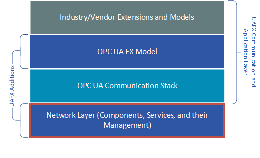
UAFX defines an application layer model and the use of common UA communication services (e.g., Client Server, PubSub), which specify mappings to the underlying network layer. The operation of UAFX in an IT/OT network requires the underlying network layers to fulfil a set of functionalities defined in this document encapsulated in the definition of components (see 5). Figure 1 highlights the definitions in this document with respect to the overall OPC UA FX communication stack architecture (see OPC 10000-80, 4.2).
This release of the document applies to Ethernet networks. Clause 5 provides an overall system description covering the features in this document and their relationship to definitions in other OPC UA specifications. Clause 6 defines networking requirements for components supporting UAFX. Clause 7 defines network service requirements.
5 System description
5.1 Overview
To ensure an interoperable, scalable, and manageable network, certain networking services need to be standardised, including address assignment, HostName resolution, and topology discovery. In addition, limits on various network quantities, such as the number of IA-stations, network diameter, and, if used, TSN Streams need to be defined to set capability expectations. Note that some of these services and quantities relate more to the network infrastructure than to the responsibilities of individual IA-stations participating in the network.
5.2 Dynamic Host Configuration Protocol
5.2.1 Overview
A UAFX Station has at least one UAFX-capable network interface. Since UAFX uses IP for different types of data exchange, each network interface shall have at least one IP address (excluding localhost) and respective interface parameters such as subnet mask, default gateway address, and DNS server address. The IP addresses of network interfaces (and respective interface parameters) of the UAFX Station are configured as a part of the bootstrapping process. This configuration can be provided in an automated manner or manually. A particular IP address allocation method is not mandated to be used as long as an IP address allocation method produces no conflict in the network.
5.2.2 Supported Features
To fulfil the aforementioned system behaviour, a UAFX Station shall support a DHCP client on each network interface, supporting configuration methods defined in IETF RFC 2131 and all features necessary to implement such methods.
5.3 HostName resolution
5.3.1 Overview
When configuring and communicating with End Station Components in an industrial network, many end users wish to use HostNames rather than IP addresses. Since the underlying transport protocols (e.g., TCP and UDP) use IP addresses, a HostName needs to first be resolved to an IP address before initiating communications. In both IT and OT networks, the Domain Name System (DNS) is commonly used when HostName resolution is required.
By virtue of using OPC UA transport mechanisms, UAFX makes provisions for using HostNames, as described in the following sections. Requirements to support HostName resolution vary by UAFX Profile, as defined in OPC 10000-84.
5.3.2 HostName resolution using DNS
There are two UAFX communication scenarios where HostName resolution could be used: with UA Client Server communications, such as during UAFX connection establishment, and PubSub communications to exchange the real-time data for a Connection.
Figure 2 illustrates the use of DNS (as specified in RFC 1034 and its related RFCs) in the establishment of a UAFX Connection between two UAFX Controllers.
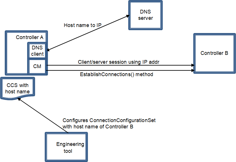
Controller A, with ConnectionManager (CM), has a DNS client and has been configured via DHCP or vendor-specific means with the IP address of the DNS server(s). The DNS server is contacted to resolve the HostName of Controller B, if not already resolved as part of UA session establishment, before issuing the EstablishConnections Method.
Figure 3 illustrates the use of DNS in conjunction with PubSub for controller-to-controller communications.
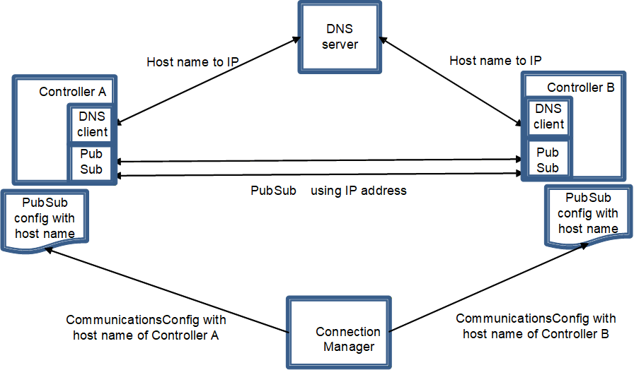
In this case, via the EstablishConnections Method, each Controller has been given a PubSub configuration containing the other Controller's HostName. In order to send and receive publications, the HostNames need to be resolved to IP addresses. Each Controller has a DNS client and, if not already resolved, needs to contact the DNS server before publishing to the subscribing Controller.
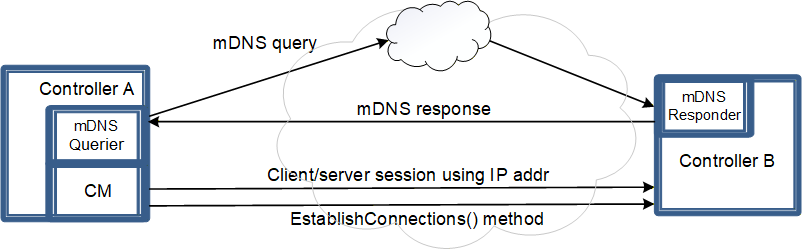
5.3.3 HostName resolution using multicast DNS (mDNS)
Multicast DNS (mDNS), as specified in IETF RFC 6762, provides HostName resolution without needing a DNS server. Hosts needing to resolve HostNames issue mDNS queries to the well-known IP multicast address for mDNS.
In discovering UAFX Servers, Clients may use mDNS directly or the local discovery server-multicast extension (mDNS-ME), as described in OPC 10000‑12.
Figure 4 illustrates the use of mDNS for HostName resolution during UAFX connection establishment.
5.4 Server announcement and discovery using mDNS
To enable Clients to discover the UAFX Server, Controllers shall support an mDNS responder and include the defined UAFX capability in its mDNS announcements and responses as defined in OPC 10000‑12. Controllers are required to support a minimal mDNS responder and include the defined UAFX capability in its mDNS announcements and responses.
In discovering UAFX servers, clients may either use mDNS directly or use the local discovery server-multicast extension (mDNS-ME), as described in OPC 10000‑12.
5.5 Network quantities
As a connected system, UAFX assumes certain capabilities to be provided in the network. UAFX mandates features such as DHCP or DNS from the device side, as described in this clause. UAFX does not mandate services on the system level (since, for instance, smaller systems do not necessarily require DHCP and DNS servers), but to ensure scalability, respective services can be expected in the system. Furthermore, aiming at networks of different sizes, the following quantities represent what can be supported in a network containing UAFX Stations:
UAFX Stations - > 1000,
Network segments - >1,
Controllers - >1,
TSN Configuration Domains - >1,
Controllers per Configuration Domain - >10,
Devices per Configuration Domain - >250,
Streams per Controller for C2C - 64,
Streams per Controller for C2D - 512.
5.6 Quality of Service
5.6.1 Overview
UAFX defines the use of different kinds of communications. For example, the exchange of control data via OPC UA PubSub, connection establishment via OPC UA Client Server, link-local communication, e.g., LLDP (see 7.3) and gPTP (see 7.4), and remote management with NETCONF (see 7.2). To support the UAFX system operation, these kinds of communications may demand different Quality of Service (QoS) in the network.
This subclause provides an overview of how the definitions in this document can be applied to a network containing UAFX Stations (see 6.4.3) and other IA-stations (see 6.4) such that Connections can be handled with appropriate QoS. With this release, UAFX Stations can use Best Effort or priority-based QoS for OPC UA PubSub traffic. In addition, enhanced priority-based QoS can be achieved in the network using the TSN mechanisms selected in this document.
To decouple the QoS specification for applications created during the application engineering phase from the actual QoS configuration in a given network, Controls Engineers define the application's QoS needs in the form of abstract QoS categories and labels. Similarly, Controls Engineers can use abstract network interface names to allow the use of VLANs as needed, e.g., for priority-based QoS at the Ethernet layer. The OPC UA Communication Stack then uses a PriorityMappingTable (see OPC 10000‑22) to translate the abstract QoS category and label of a Connection to concrete priority values in the message. Similarly, the UA Communication Stack can use the representation of VLAN interfaces in the OPC UA Information Model to resolve abstract VLAN interface names to VLAN IDs in the transmitted packets.
5.6.2 Traffic Priority
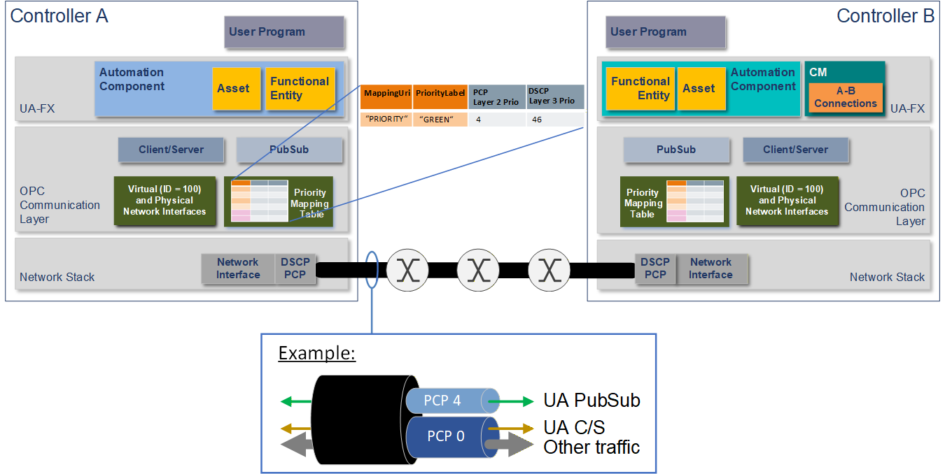
Table 1 defines a recommended usage of priorities for various types of traffic in networks containing UAFX Stations. Combined with the traffic class mapping priority defined in 6.4.3, these recommendations provide consistent, system-wide behaviour for networks that do not currently use the recommended priority values for other purposes.
| PCP | DSCP | Recommended usage |
| 7 | -1 | Reserved |
| 6 | -1 | Reserved |
| 5 | 48 | Network control2 (gPTP, LLDP, loop prevention) |
| 4 | 46 | Green4 (UA PubSub, see 6.5.4) |
| 3 | -1 | Reserved |
| 2 | 16 | Connection establishment (UA Client Server3), remote management2 (NETCONF) |
| 0 | 0 | Best Effort |
| 1 | 8 | Background |
NOTE 1 The entries in the table are in the order of effective priority of the packets on the network and not in the order of priority values (PCP and DSCP). NOTE 2 IEEE Std 802.1Q‑2022, I.4 explains the rationale for inverting PCP 0 and 1. PCP of 0 is used for default priority and Best Effort. Tagging a frame with PCP 1 allows explicit indication of traffic that can be treated with a lower priority than Best Effort. This same rationale applies to the default Priority to Traffic Class Mapping in 6.4.3. NOTE 3 The DSCP values for Network Control, Best Effort, and Background have been selected from IETF RFC 4594, Figure 3. NOTE 4 The DSCP value for GREEN is selected from the IANA DSCP Pool 1 Codepoints registry value for Expedited Forwarding defined in IETF RFC 3246. NOTE 5 The default PCP and DSCP values for any type of traffic without explicit priority configuration are equal to Best Effort. | ||
1 Additional DSCP values may be defined in a future release of this document. 2 Currently, there is no OPC UA means for the assignment of priority information for these services. This is expected to be added in a future release, e.g., through IEC/IEEE 60802. 3 The OPC UA Information Model currently does not allow the assignment of priority information for UA Client Server messages. A future release is expected to allow UA Client Server QoS configuration in addition to UA PubSub. 4 "Green" corresponds to the OPC UA PriorityLabel opc.qos.lbl://green, which this release of the document supports for OPC UA PubSub-based exchange of control data with UAFX. | ||
Figure 5 shows an example of an application running on two Controllers using different priorities on a network. One priority carries OPC UA PubSub messages with an elevation to PCP 4, and another carries all other messages in the same lower priority, including OPC UA Client Server.
5.6.3 VLANs
Following the concept of decoupling the application from the network configuration and in concert with the PCP values defined in Table 1, specifies a default, abstract VLAN interface name and associated VLAN ID value. In deployments intended to use priority-based QoS at the Ethernet layer, this abstract VLAN interface name can be used for ease of use during Connection engineering if the VLAN interface name has not explicitly been adapted. Moreover, the mapping from the abstract VLAN interface name to a concrete VLAN ID can still be adapted prior to connection establishment (see 5.6.4.5). This decoupling allows for any necessary adjustments, e.g., if the default VLAN ID is already in use or deployment-specific requirements demand the use of a different VLAN ID.
Priority-based QoS at the Ethernet layer also relies on the consistent support and configuration of VLANs in the network containing UAFX Stations. Therefore, it is recommended that all Bridge Components (see 6.2) in such networks are configured to forward VLAN-tagged Ethernet frames with the VLAN IDs used by the attached UAFX Station. The overall configuration results in tagged and untagged traffic originating from a UAFX Station.
5.6.4 Example UAFX engineering workflow with a focus on networking QoS
5.6.4.1 General
The following subclauses describe an example workflow to achieve the configuration and operation shown in Figure 5. As mentioned in 1, with this release, vendor-specific means are required for all networking-related End Station and Bridge Component configurations, including VLAN configuration, time synchronisation, and QoS.
The engineering workflow described in this clause follows the general workflow from OPC 10000-80 for the configuration of Connections between FunctionalEntity inputs and outputs. The workflow described in this clause goes into the details related to configuring the QoS required by those Connections. This workflow is divided into four phases: Application and QoS engineering, network configuration, system integration, and connection establishment and operation.
The example in this clause illustrates the configuration and start-up of a single communication flow between two Controllers, i.e., data is only shared in one direction, requiring a single Descriptor describing this data to be exported from an engineering tool describing one of the Controllers. UAFX Applications will typically be sharing data in both directions between the Controllers, thus requiring Descriptors to be shared in both directions.
The default networking configuration of End Station Components defined in the application and QoS engineering phase (see 5.6.4.2) of the workflow allows UAFX Stations to operate out-of-the-box with no additional networking configuration when used on a network designed with these requirements in mind. This default configuration can be adapted, e.g., to accommodate the needs of an existing network, as illustrated in the workflow's system integration phase (see 5.6.4.4).
5.6.4.2 Application and QoS engineering
During the application and QoS engineering phase, Controls Engineers, working in an OfflineEngineering environment, first create the user programs and UAFX Applications and set up the (default) networking configuration of the End Station Components (see 6.3) on their Controller. Next, Controls Engineers set up the Connection configurations needed for sharing data between Controllers. As a final step, Connection configurations are transferred to a ConnectionManager that establishes the Connections during the workflow's connection establishment and operation phase (see 5.6.4.5). This subclause describes the details of these steps, including the setup of network interface configurations and Connection information provided to the ConnectionManager. Complete details of the ConnectionManager are defined in OPC 10000‑81.
Figure 6 illustrates an example where two engineers jointly create a UAFX Application containing Controller A and Controller B while separated in time and space and potentially without physical devices. For example, Controller A might control a conveyor belt, and Controller B might be a line controller using this conveyor belt (Controller) as part of controlling a production line. Descriptors, defined in OPC 10000‑83, enable the engineers to share application information between their respective engineering tools. In this example, Controller B hosts the ConnectionManager (CM) for configuring and establishing the Connection.
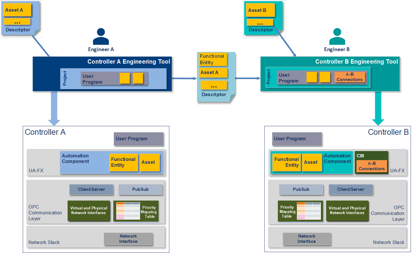
As the first step in this example, Engineer A creates Controller A's User Program using an engineering tool specific to Controller A. In addition to the Controller's program, the engineering tool is used to create the UAFX Information Model representing that program. This Information Model consists of an AutomationComponent representing the entity being created by Engineer A. Part of the AutomationComponent is the functional model representing the logical functionality of the User Program. FunctionalEntities contained in the AutomationComponent represent that functional model. Input and output Variables in the FunctionalEntity expose the data to be exchanged using Connections with FunctionalEntities in another Controller. The Variables PublisherCapabilities and SubscriberCapabilities, also contained in the AutomationComponent, describe communication capabilities such as publishing intervals and, most important for the scope of this example workflow, the QoS capabilities that this AutomationComponent supports. OPC 10000‑81 provides details about the AutomationComponent, FunctionalEntity, the functional model, PublisherCapabilities, and SubscriberCapabilities.
To configure the use of priority-based QoS for a UAFX Application, Engineer A sets up and references a PriorityMappingTable from each physical network interface available to the UAFX Application. Virtual interfaces inherit the PriorityMappingTable from the physical interface if they do not reference a PriorityMappingTable directly. A PriorityMappingTable consists of entries that map a combination of abstract QosCategory and PriorityLabel values to concrete PCP and DSCP values for priority-based QoS at the Ethernet and IP layer, respectively. The default PriorityMappingTable settings for priority-based QoS with UAFX are defined in 6.5.4. OPC 10000‑14 provides detailed descriptions of QosCategory and PriorityLabel.
For priority-based QoS at the IP layer, no additional configuration is needed. For priority-based QoS at the Ethernet layer, the UAFX Station has default VLAN interfaces created as defined in . To this end, Engineer A may modify the VLAN IDs or add additional VLAN interfaces. The VLAN IDs or additional VLAN interfaces can also be changed during the system integration step of the workflow (see 5.6.4.4) as appropriate for the given deployment.
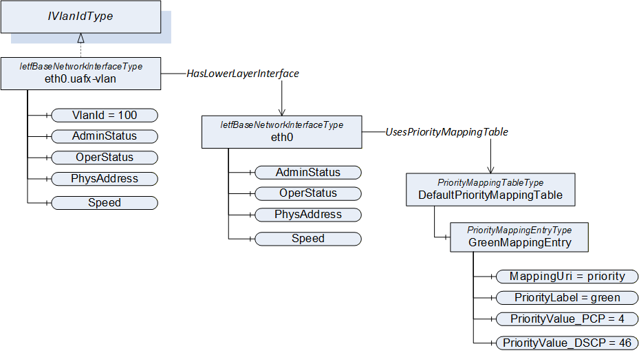
In either case, the VLAN interface is represented in the Information Model by an IetfBaseNetworkInterfaceType object, as described in . Figure 7 illustrates the Information Model of a physical interface with the name "eth0" referencing a PriorityMappingTable, DefaultPriorityMappingTable, with at least the PriorityMappingEntries defined in 6.5.4, and an associated VLAN interface named "eth0.uafx-vlan" and VID set to 100 as defined in .
Once the configuration for Controller A is complete, Engineer A transfers the User Program, PriorityMappingTable, and all created network interfaces to Controller A using this Controller's engineering tool. Engineer A also exports a Descriptor that is shared with Engineer B to complete the UAFX Application configuration. The exported Descriptor includes, amongst others, the AutomationComponent, FunctionalEntity(ies), PublisherCapabilities and SubscriberCapabilities (including QosCategories and PriorityLabels), PriorityMappingTable, and IetfBaseNetworkInterfaces representing Controller A's User Program. OPC 10000‑81 provides the detailed definitions of ConnectionManager, PublisherCapabilities and SubscriberCapabilities, and PubSubCommunicationFlowConfiguration.
Engineer B creates the User Program and the UAFX Information Model for Controller B using an engineering tool specific to Controller B, much as Engineer A did for Controller A. Engineer B also imports the Descriptor exported by Engineer A into Controller B's engineering tool, allowing Engineer B to configure the Connections between Controller A's and Controller B's FunctionalEntity(ies).
By importing the Descriptor from Controller A, Controller B's engineering tool contains the UAFX Information Model for both Controllers, including the configuration of both Controllers' AutomationComponent's PublisherCapabilities and SubscriberCapabilities, PriorityMappingTable, and IetfBaseNetworkInterfaces. With this information, Engineer B configures the QoS and addresses for each Connection between the Controllers by setting the sender and receiver Address, QosCategory, and PriorityLabel Variables in the ConnectionManager PubSubCommunicationFlowConfiguration.
Figure 8 illustrates the Variables used by Controller B's engineering tool for configuring the Connection's QoS. This step involves setting the QosCategory and PriorityLabel Variables in the ConnectionManager's PubSubCommunicationFlowConfiguration Variable. The available values for QoS are derived from the respective AutomationComponent's PublisherCapabilities and SubscriberCapabilities Variables. More precisely, each Controller's supported QoS options are described in the SupportedQos Array contained in the PublisherCapabilities and SubscriberCapabilities Variables. Each element of the SupportedQos Array, in turn, contains a single QosCategory value with its related DatagramQos Array. For QosCategory "opc.qos.cat://priority", the DatagramQos Array contains a single element containing the supported PriorityLabel (e.g., "opc.qos.lbl://green").
Engineering tools can ensure QosCategory is set consistently in both the sender and receiver by only listing those elements having the same QosCategory values in both Controller A and Controller B, i.e., the intersection of values from both Controllers. The list of supported PriorityLabels can be different in each Controller, so separate PriorityLabel lists are presented by the engineering tool for each side of the Connection.
In addition to the QosCategory and PriorityLabel, Engineer B can set the interface configuration in the NetworkInterface Variable to be used by a Connection as part of the PubSubCommunicationFlowConfiguration sender and receiver Address parameters. A NetworkInterface Variable may either be the BrowseName of a physical interface or a VLAN interface. The NetworkInterface Variable may also be set to an empty string. In this case, the AutomationComponent chooses the appropriate network interface (e.g., using a routing table). All available network interfaces available to the UAFX Application, including VLAN interfaces, are contained in the NetworkInterfaces Folder defined in OPC 10000-22. The System Commissioner can finish the configuration of the Connections (i.e., modify the network interface and QoS selection) in the system integration phase (see 5.6.4.4).
Once the Connection configuration is complete, Engineer B transfers the Connection configurations for the ConnectionManager, including their QoS requirements, User Program, and network interface configuration, into Controller B using a vendor-specific engineering tool.
5.6.4.3 Network configuration
During the network configuration phase, the Network Engineer uses remote management (see 7.2) or vendor-specific means to discover the network topology (see 7.3) and further configures the interconnected UAFX Stations and network infrastructure components.
In deployments intended to use priority-based QoS at the Ethernet layer, it is recommended that all Bridge Components are configured to forward VLAN-tagged Ethernet frames with the VLAN ID(s) used by the attached UAFX Stations. To this end, the Network Engineer configures Static VLAN Registration Entries (see IEEE Std 802.1Q‑2022, 8.8.2) for each of these VLAN IDs for those Bridge Components. The Static VLAN Registration Entries add those ports that are connected to a UAFX Station or an IA-station interconnecting UAFX Stations in a network to the tagged member sets of the VLAN IDs. As a result, the VLAN tags are transmitted from the sending UAFX Station to the receiving UAFX Station.
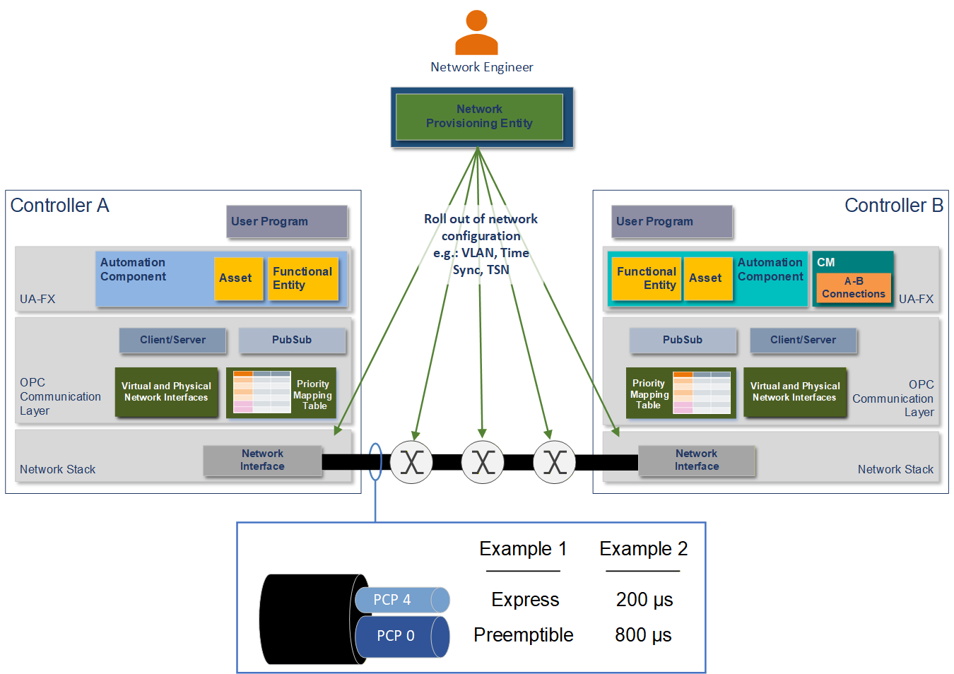
In addition, the Network Engineer may also configure the use of selected TSN mechanisms in the network as appropriate for the given deployment scenario and application QoS requirements. Figure 9 illustrates two of the many different available TSN mechanism configuration options. Example 1 illustrates a configuration that entails setting PCP 4 (see Table 3) to Express and all other PCPs as Preemptible using the Frame Preemption mechanism (see 6.2.2 item g). Alternatively, as shown in Example 2, the first 200 µs of a 1 ms cycle time may be reserved for PCP 4, with the remaining 800 µs used for the remaining PCPs using the enhancements for scheduled traffic mechanism (see 6.2.2 item f).
5.6.4.4 System integration
During the system integration phase, a System Commissioner makes the necessary adjustments to adapt the Connections and network configurations for the existing network using a generic OPC UA Client or vendor-specific engineering tool, as illustrated in Figure 10.
Clause specifies the default VLAN interfaces with default VLAN IDs. If the System Engineer used deviating VLAN IDs, the System Commissioner has to update the VLAN interfaces on the UAFX Stations. Additionally, new VLAN interfaces can be created if necessary.
Clause 6.5.4 specifies the default PriorityMappingTable assigned to the physical interfaces. Only if the Network Engineer requires a different usage of the priority values for the configured QoS mechanisms in the network does the System Commissioner update the PriorityMappingTable on all UAFX Stations accordingly (i.e., the PCP and DSCP values for the different QosCategory-PriorityLabel combinations).
Finally, once the network interfaces and PriorityMappingTable are configured, the System Commissioner may update the PubSubCommunicationFlowConfiguration Variable in the ConnectionManager's Information Model to adapt the Connection configurations for QoS settings and network settings such as setting destination IP addresses and network interface names. This step is only necessary if the deployment of the UAFX Station uses different values, as available in the Descriptor in 5.6.4.2. Clause 5.6.4.2 describes the Information Model objects and Variables involved in making these adjustments.
5.6.4.5 Connection establishment and operation
The connection establishment and operation phase begins with the ConnectionManager establishing the Connections described in its Information Model. Connection establishment is either initiated by the ConnectionManager's internal logic or by a Client invoking a Method on the ConnectionManager as described in OPC 10000‑81.
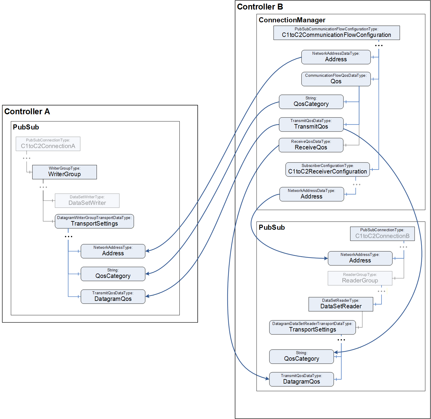
The ConnectionManager establishes Connections using the Connection configuration as set up by the Controls Engineer (see 5.6.4.2) and System Commissioner (see 5.6.4.4). Figure 11 illustrates setting up the PubSubConfiguration in Controller A and Controller B, focusing on QoS and Address as contained in the PubSubCommunicationFlowConfiguration. To this end, the ConnectionManager invokes the EstablishConnections Method on the AutomationComponents that reference the FunctionalEntities being connected, as depicted in Figure 12 label A. For details on Address and QoS, see OPC 10000‑14.
Once a Connection is established and communication begins, as illustrated in Figure 12 label B, the OPC UA Application and Communication Layer (see Figure 1) uses the QosCategory and PriorityLabel values in the WriterGroup with the PriorityMappingTable to derive the actual PCP and DSCP priority values to use for the corresponding OPC UA PubSub messages on the wire. Similarly, it uses the Address Variable in the WriterGroup to derive the VLAN ID value to be used in the VLAN tag, as illustrated in Figure 12 label C, for priority-based QoS with Ethernet. See OPC 10000‑14 for a detailed description of how the PriorityMappingTable and Address Variable are used with PubSub communications for priority-based QoS.
6 Component model and requirements
6.1 General
This clause defines a component model to structure the selection of functional networking features. This component model consists of Bridge Component (see 6.2), End Station Component (see 6.3), IA-station (see 6.4), and UAFX Station (see 6.5).
6.2 Bridge Component definitions
6.2.1 Overview
A Bridge Component interconnects two or more network segments and forwards packets between them. This document supports the Bridge Component features listed in 6.2.2, including link speeds of 10 Mb/s to 10 Gb/s.
6.2.2 Bridge Component feature selection
A Bridge Component may support the following features:
C-VLAN component requirements as defined in IEEE Std 802.1Q‑2022, 5.5.
Strict priority algorithm for transmission selection as defined in IEEE Std 802.1Q‑2022, 8.6.8.1 on each port for each traffic class
Regenerating priority as defined in IEEE Std 802.1Q‑2022, 6.9.4
Frame filtering as defined in IEEE Std 802.1Q‑2022, 5.4.1, Item h)
Per-stream filtering and policing as defined in IEEE Std 802.1Q‑2022, 5.4.1.8
Enhancements for scheduled traffic as defined in IEEE Std 802.1Q‑2022, 5.4.1, Items ac) and ad)
Frame Preemption as defined in:
IEEE Std 802.1Q‑2022, 5.4.1, Item ae)
IEEE Std 802.3‑2018, Clause 99 (Interspersing Express Traffic Support), including support of the Additional Ethernet Capabilities TLV in an LLDPDU per IEEE Std 802.3‑2018, 79.3.7
TE-MSTID as defined in IEEE Std 802.1Qcc‑2018, 5.5.2 Items a) and b).
6.3 End Station Component definitions
6.3.1 Overview
An End Station Component is the source or destination of network traffic.
6.3.2 End Station Component feature selection
An End Station Component may support the following features:
Transmission and reception of C-VLAN tagged frames.
6.4 IA-station definitions
6.4.1 Overview
IA-stations can be a simple End Station Component (see 6.3) acting as the source or destination for industrial data traffic. IA-stations may also include a Bridge Component (see 6.2). More complex IA-stations incorporating several End Station Components and Bridge Components within one device can also be found in industrial automation (e.g., a Controller with multiple modules).
An IA-station can include one or more IA-station functions acting as the source or destination for data traffic. These functions, located in the End Station Components, include industrial automation applications, Remote Management, and other applications or services such as Time Synchronisation or Topology Discovery. IA-station functions can reside in a single or multiple End Station Components within a given IA-station.
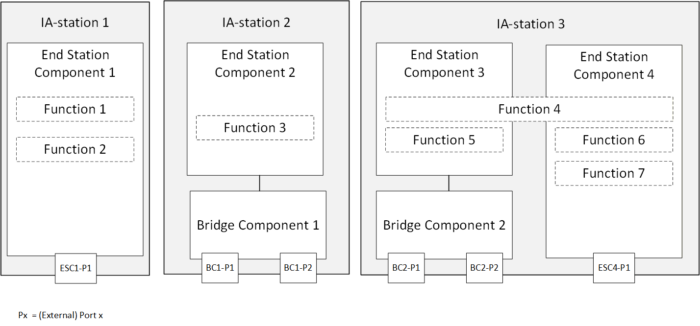
Figure 13 shows three examples of an IA-station. IA-station 1 comprises one End Station Component hosting two IA-station functions. IA-station 2 comprises one End Station Component hosting one IA-station function and one Bridge Component. IA-station 3 comprises a Bridge Component and two End Station Components hosting four IA-station functions. IA-station 3 shows that an IA-station function can span across multiple End Station Components.
6.4.2 IA-station requirements
An IA-station shall:
comprise at least one conformant End Station Component as defined in 6.3,
support topology discovery as defined in clause 7.3.
An IA-station may:
comprise one or more conformant Bridge Components as defined in 6.2,
support remote management as defined in clause 7.2,
support time synchronisation as defined in clause 7.4,
support middleware applications.
6.4.3 Default Priority to Traffic Class Mapping
Ethernet QoS mechanisms are defined to operate on PCP or traffic classes. For the latter, a mapping between the PCP value in the frame and the associated TC is needed. If the PCP to TC mapping has not been explicitly configured, an IA-station shall use the mapping defined in IEEE Std 802.1Q‑2022, Table 8-5.
6.5 UAFX Station definitions
6.5.1 Overview
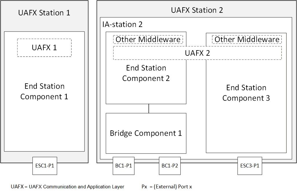
A UAFX Station is an IA-station (see 6.4) supporting the UAFX communication and application layer (see Figure 1). The UAFX communication and application layer is a logical component acting as a source of and/or destination for link layer data traffic. Thus, each UAFX Station incorporates at least one End Station Component where the UAFX communication and application layer can be located. Figure 14 shows that the UAFX communication and application layer can reside in one or multiple End Station Components.
6.5.2 UAFX Station requirements
A UAFX Station shall:
comprise a conformant IA-station,
support middleware modelling of network interfaces and QoS in the UAFX communication and application layer:
priority mapping configuration representation as defined in OPC 10000‑22, including the PriorityMappingTableType, MappingTables Folder, and the UsesPriorityMappingTable ReferenceType (see 6.5.4);
network interface representation as defined in OPC 10000-22, including the IetfBaseNetworkInterfaceType, the IIetfBaseNetworkInterfaceType and IIeeeBaseEthernetPortType Interfaces, and the NetworkInterfaces Folder (see );
C-VLAN configuration representation as defined in OPC 10000‑22, including the IVlanIdType Interface and the HasLowerLayerInterface ReferenceType (see ).
LLDP information representation as defined in OPC 10000‑22, including at least one instance of the LldpInformationType, and if the UAFX Station contains one or more Bridge Components, at least one instance of the RemoteSystemsData Component of the LldpInformationType.
6.5.3 Network interface representation and default configuration
Each physical network interface available to the UAFX Application shall be represented as an instance of IetfBaseNetworkInterfaceType in the NetworkInterfaces Folder defined in OPC 10000‑22. All VLAN interfaces attached to these physical network interfaces shall be represented as defined in OPC 10000‑22. A UAFX Station shall at least provide the default VLAN interface with the BrowseName as defined in Table 2 and a HasLowerLayerInterface reference to the respective physical network for each of these physical network interfaces. If the VlanId value has not been explicitly configured for this default VLAN interface, the VlanId shall assume the value defined in Table 2.
| BrowseName | VlanId (default) |
|---|---|
| <physical-interface>. | 100 |
6.5.4 Default PriorityMappingTable configuration
A UAFX Station shall provide a PriorityMappingTable with at least the default entries for MappingUri/QosCategory and PriorityLabel as defined in Table 3. If PCP and DSCP values have not been explicitly configured (i.e., to accommodate the needs of an existing network), PriorityValue_PCP and PriorityValue_DSCP shall assume the values defined in Table 3.
| MappingUri/QosCategory | PriorityLabel | PriorityValue_PCP (default) | PriorityValue_DSCP (default) |
|---|---|---|---|
| opc.qos.cat://priority | opc.qos.lbl://green | 4 | 46 |
Each physical network interface available to the UAFX Application, represented by an instance of IetfBaseNetworkInterfaceType in the NetworkInterfaces Folder, shall have a reference to an instance of PriorityMappingTableType that is exposed to OPC UA Clients, e.g., for adaptation during the system integration phase (see 5.6.4.4), as defined in OPC 10000‑22. The referenced PriorityMappingTableType instance shall include the AddPriorityMappingEntry and DeletePriorityMappingEntry Methods.
7 Services and capabilities
7.1 General
This clause defines network services needed for the operation of UAFX and their remote management (see 7.2). Network services defined in this document's release include topology discovery (see 7.3) and time synchronisation (see 7.4).
7.2 Remote Management
7.2.1 Overview
This subclause defines remote management for UAFX Stations for networking features, including those defined in Clause 6, as well as the services and capabilities defined in Clause 7. For interoperable remote management, UAFX uses the Network Configuration Protocol (NETCONF) as a remote management protocol (see 7.2.2).
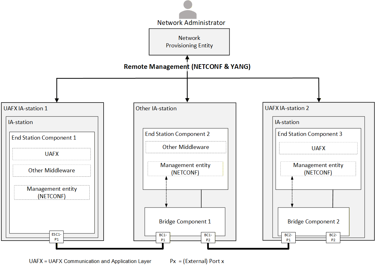
Figure 15 shows an example network consisting of two UAFX Stations and one IA-station. The Network Provisioning Entity uses NETCONF as the common remote management protocol for network configuration during commissioning (see OPC 10000-80, Figure 6) as required for the site. This configuration may contain, amongst others, VLAN configuration, IP subnet configuration, time synchronisation configuration, and QoS configuration. In addition, remote management enables network monitoring and communication fault diagnostics.
7.2.2 NETCONF
A UAFX Station supporting remote management shall support a Network Configuration Protocol (NETCONF) server as defined in IETF RFC 7589 (NETCONF over TLS).
A single management entity controls all components of a UAFX Station. Figure 16 shows a UAFX Station comprised of two End Station Components and one Bridge Component, all controlled by a single management entity.
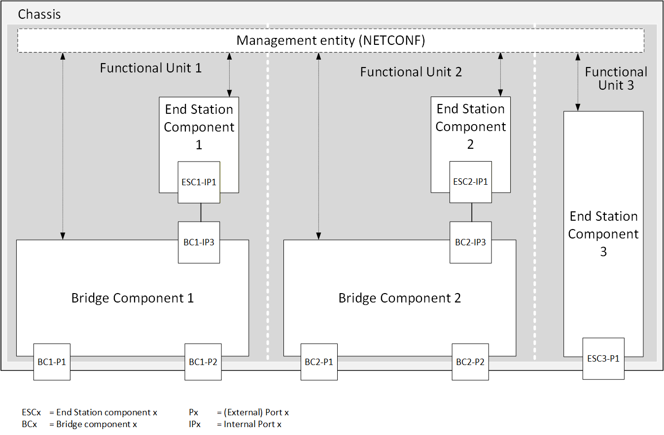
NETCONF messages are recommended to be transmitted using priority information defined for Remote Management in Table 1.
7.3 Topology Discovery
7.3.1 Overview
UAFX defines the use of LLDP for the discovery of IA-stations, their external ports, and their external connectivity (see 7.3.2). A Topology Discovery Entity (TDE) queries this information by remote management to derive the physical network topology and provide it to a System Engineer (see Figure 17).
7.3.2 IEEE 802.1AB (LLDP)
7.3.2.1 Overview
UAFX defines the use of the LLDP protocol for IA-stations to announce themselves to their peers for device and topology discovery. By default, announcements from a UAFX Station contain, among others, the management address(es) and system capabilities (see 7.3.2.2.4).
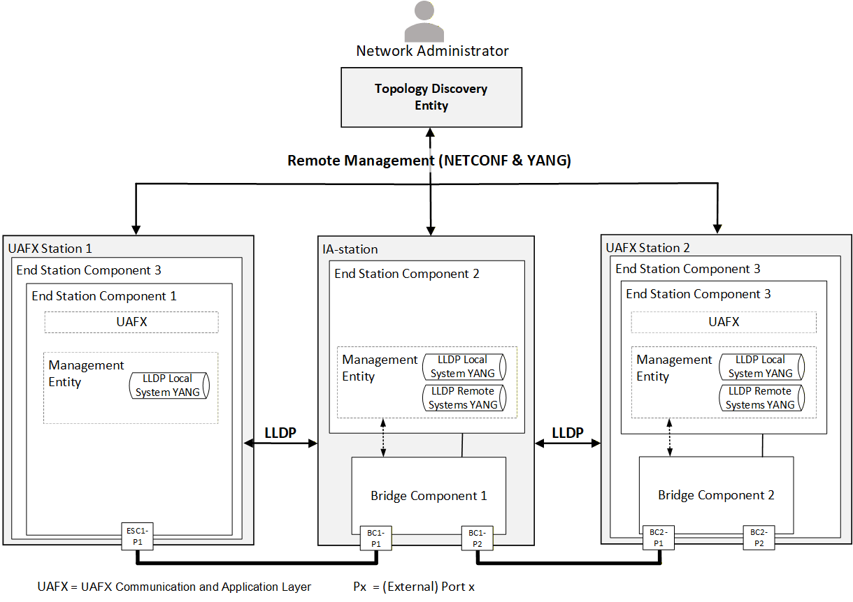
For adaptability of the operational behaviour and the announced information of LLDP, all UAFX Stations support the LLDP local system YANG (see 7.3.2.2.5). UAFX Stations that include a Bridge Component also receive and store LLDP announcement information received from their peers in the LLDP remote systems YANG.
A remote management protocol (see 7.2) is used between the TDE and IA-stations to query the local system YANG and remote systems YANG. The management address information in the retrieved remote systems YANG allows the TDE to discover and query new IA-stations. The correlation of an IA-station's local system data with a neighbouring IA-station's remote systems data enables the TDE to discover the physical network topology.
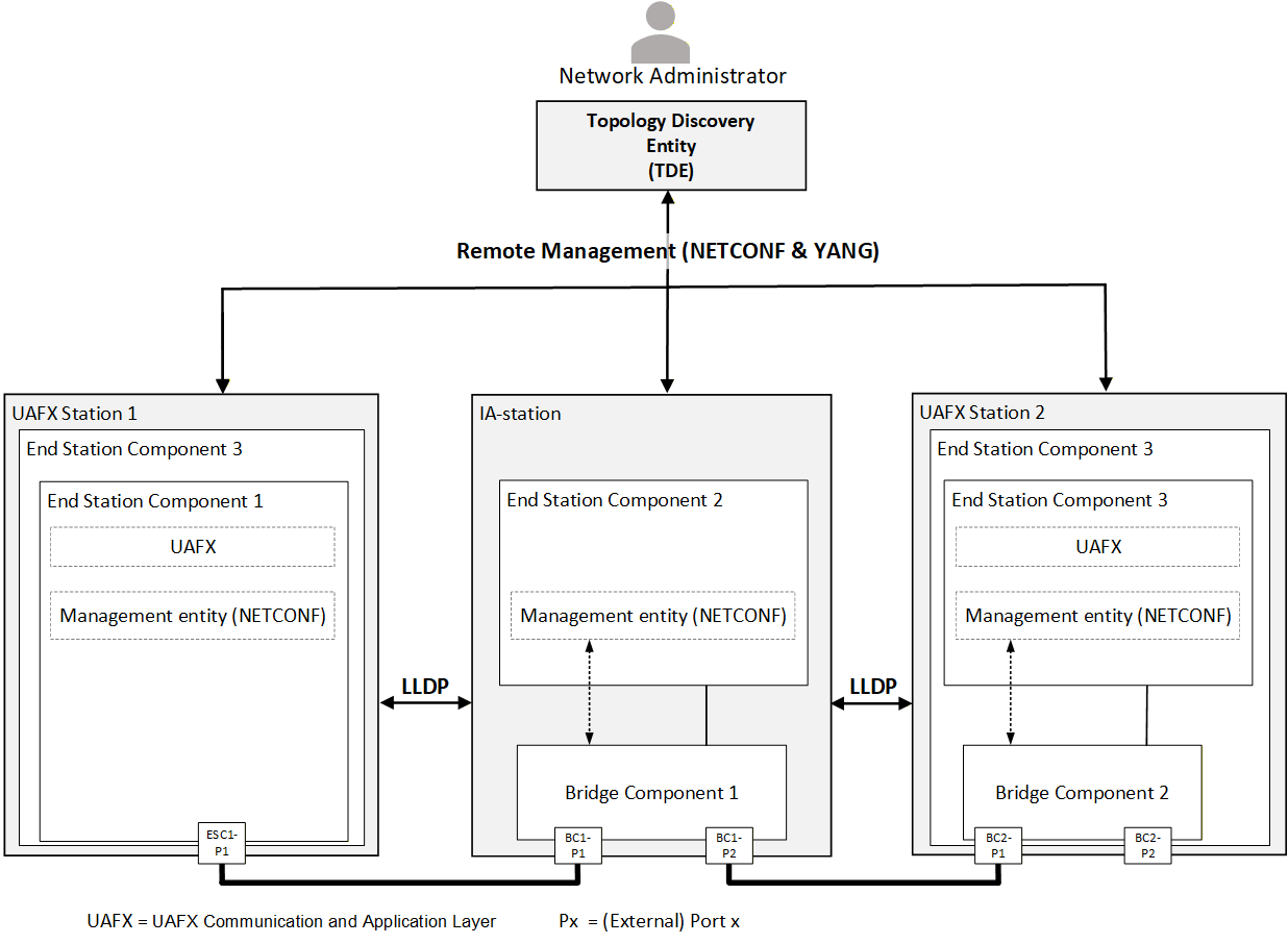
Figure 18 illustrates an example network showing the LLDP agents and their management in a UAFX Station consisting of a single End Station Component, an IA-station, and a UAFX Station with an End Station Component and a Bridge Component.
7.3.2.2 Profile Definitions
7.3.2.2.1 Version
A UAFX Station shall implement LLDP according to IEEE Std 802.1AB-2016, 5.3, following the definitions in 7.3.2.2.
7.3.2.2.2 Operational control parameters
LLDP defines several operational parameters that control the protocol behaviour (see IEEE Std 802.1AB‑2016, 10.5.1). These parameter definitions apply to all external ports of a UAFX Station.
A UAFX Station shall support LLDP transmit mode (adminStatus enabledTxOnly) on an external End Station Component port and may support transmit and receive mode (adminStatus enabledRxTx) on that port (see IEEE Std 802.1AB-2016, 10.5.1).
A UAFX Station shall support LLDP transmit and receive mode (adminStatus enabledRxTx) on an external Bridge Component port (see IEEE Std 802.1AB-2016, 10.5.1).
7.3.2.2.3 LLDPDU transmission, reception, and addressing
The destination address shall be the nearest bridge group MAC address, i.e. 01-80-C2-00-00-0E, to limit the scope of LLDPDU propagation to a single physical link (see IEEE Std 802.1AB‑2016, 7.1 item a).
It is recommended that LLDPDUs be transmitted using the traffic class associated with Network Control as defined in Table 1 and derived from 6.4.3.
7.3.2.2.4 TLV selection
7.3.2.2.4.1 General
A UAFX Station transmitting LLDPDUs shall include the LLDP TLVs selected in this sub-clause. A UAFX Station receiving LLDPDUs shall process LLDPDUs and include the information in the LLDP Remote System's YANG.
Each transmitted LLDPDU shall contain the following LLDP TLVs defined in IEEE 802.1AB-2016, 8.5:
exactly one Chassis ID TLV, as defined in 7.3.2.2.4.2,
exactly one Port ID TLV, as defined in 7.3.2.2.4.3,
exactly one Time To Live TLV,
exactly one System Capabilities TLV, as defined in chapter 7.3.2.2.4.4,
one or more Management Address TLVs, as defined in 7.3.2.2.4.5, and
zero or more additional TLVs not listed in this requirement.
7.3.2.2.4.2 Chassis ID TLV
The Chassis ID field shall contain the same value for all transmitted LLDPDUs independent from the transmitting port of the UAFX Station, i.e., be a non-volatile, UAFX Station-unique identifier.
The Chassis ID subtype field should contain subtype 4, indicating that the Chassis ID field contains a MAC address to achieve the Chassis ID's desired deployment-wide uniqueness. For UAFX Stations with multiple unique MAC addresses, any one of the UAFX Station's MAC addresses may be used and shall be the same for all external ports of that UAFX Station.
7.3.2.2.4.3 Port ID TLV
The Port ID field shall contain the same value for all transmitted LLDPDUs for a given external port, i.e., be a non-volatile, UAFX Station-unique identifier of the LLDPDU-transmitting port.
The Port ID subtype field should contain subtype 5, indicating that the Port ID field contains the interface name (name) according to IETF RFC 8343.
7.3.2.2.4.4 System Capabilities TLV
A UAFX Station consisting of only one or more End Station Components shall set the system and enabled capabilities fields to Station Only (i.e., bit 8 set to "1") for all transmitted LLDPDUs.
A UAFX Station with at least one End Station Component and at least one Bridge Component shall set the system and enabled capabilities fields to Station Only (i.e., bit 8 set to "1") and C-VLAN component (i.e., bit 9 set to "1") for all transmitted LLDPDUs.
7.3.2.2.4.5 Management Address TLV
A UAFX Station supporting remote management shall announce at least one IPv4 address by which its management entity (see 7.2.2) can be reached.
7.3.2.2.5 Remote management
A UAFX Station supporting remote management (see 7.2) shall implement LLDP management according to IEEE 802.1ABcu-2021, 5.3 Item o).
A UAFX Station supporting the remote systems YANG shall be able to store information from at least one neighbour per external port. Receiving LLDPDUs from more neighbours than supported on a given port shall result in the last one received being saved to the remote systems YANG as described in IEEE Std 802.1AB‑2016, 9.2.7.7.5.
7.4 Time Synchronisation
7.4.1 Overview
UAFX defines the use of a time synchronisation protocol to ensure a common sense of time among participating IA-stations.
7.4.2 IEEE Std 802.1AS-2020
7.4.2.1 Overview
UAFX defines the use of gPTP as defined in IEEE Std 802.1AS‑2020 for the time synchronisation of UAFX Stations. Figure 19 illustrates an exemplary time-synchronised network with two gPTP domains (see 7.4.2.1.1). The usage of an application clock as ClockSource or ClockTarget depends on the IEEE Std 802.1AS defined role for synchronisation. Each instance of ClockSource or ClockTarget is bound to one PTP Instance. The number and type of PTP Instances residing on a UAFX Station depend on the gPTP domains it participates in and its composition, e.g., the presence of a Bridge Component. A UAFX Station can host more than one PTP Instance, e.g., UAFX Stations 1 and 2. A Grandmaster PTP Instance can reside on any grandmaster-capable UAFX Station, e.g., UAFX Station 3. UAFX Station 2 and IA-station support the forwarding of corrected time information in both gPTP domains via PTP Relay Instances (see 7.4.2.1.2).
The gPTP generates a tree-structure clock relationship between PTP Instances in the network. The clocks in all PTP Instances within a gPTP domain derive their time from a clock known as the Grandmaster Clock.
The following subclauses provide further informative descriptions of IEEE Std 802.1AS‑2020 terminology and how it applies to UAFX.
7.4.2.1.1 gPTP domains
IEEE Std 802.1AS‑2020 defines a gPTP domain in which system timing is consistent. A gPTP domain defines the scope of gPTP message communication, state, operations, parameters, and timescale. The Grandmaster PTP Instance is the root of a gPTP domain.
UAFX supports the following two types of gPTP domains:
Working Clock domain
Global Time domain
Working Clock domain maintains a common sense of time for use cases such as enhancements for scheduled traffic (see IEEE Std 802.1Q).
Global Time domain (e.g. wall clock) maintains a common sense of time across an industrial automation network for use cases such as sequence of events.
7.4.2.1.2 PTP Instances
There are two types of PTP Instances used in a gPTP domain:
PTP End Instance
PTP Relay Instance
A PTP Instance operates in a single Bridge Component or End Station Component within exactly one gPTP domain. A UAFX Station can contain more than one PTP Instance in the same gPTP domain (see 7.4.2.1.4).
7.4.2.1.3 PTP Port
PTP Instances interface with the communications network using logical entities called PTP Ports.
7.4.2.1.4 Examples of PTP in a UAFX Station
A UAFX Station can support one or more gPTP domains. Each gPTP domain is represented by a PTP Instance, which can have an associated ClockSource or ClockTarget. A PTP Instance with an associated ClockSource is a Grandmaster PTP Instance. A ClockSource and ClockTarget can serve as a provider of time for a UAFX Application (e.g., sequence of events).
Figure 20 shows an example of a UAFX Station consisting of a single End Station Component supporting one gPTP domain. Figure 21 shows an example of a UAFX Station consisting of a single End Station Component supporting two gPTP domains. Each gPTP domain has an associated PTP End Instance, which connects via a PTP Port to an Ethernet port.
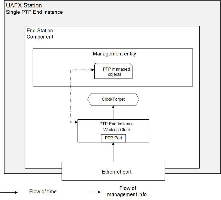
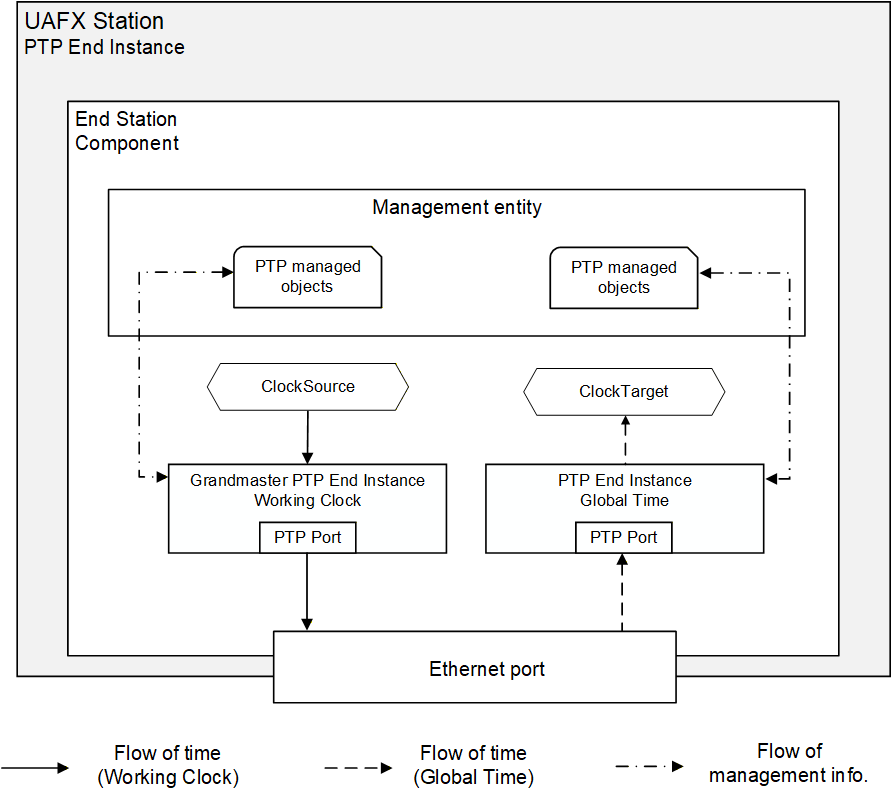
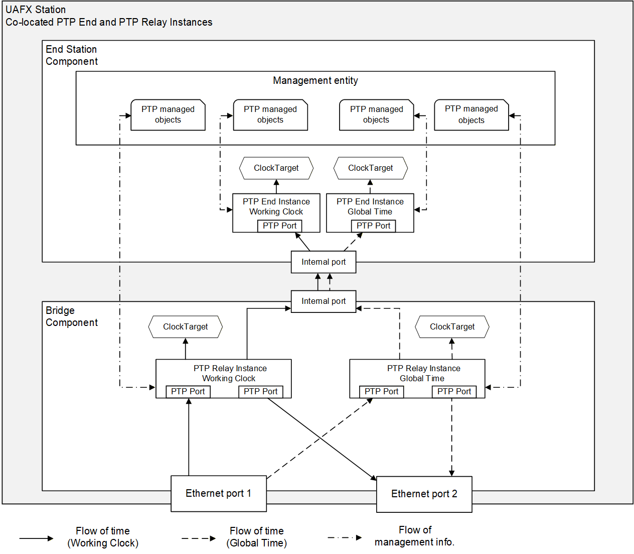
Figure 22 shows an example of a UAFX Station consisting of a single End Station Component and Bridge Component, each supporting two gPTP domains. This example includes Bridge Component ClockTargets and End Station Component PTP End Instances and ClockTargets for both domains. ClockTargets and PTP End Instances may be omitted in an implementation depending on the expected usage of time.
7.4.2.1.5 Engineered time synchronisation spanning tree
Engineered time synchronisation spanning tree (sync tree) for a given gPTP domain refers to the usage of external port configuration instead of BMCA to construct a desired sync tree with the Grandmaster PTP Instance as the root (see IEEE Std 802.1AS‑2020, 10.3.1).
One of the advantages of engineered sync trees is to enable a planned, deterministic, and stable configuration of the IEEE Std 802.1AS‑2020 sync tree for a given gPTP domain, e.g., prevent sync tree changes in case of UAFX Station addition or removal from the network. Working Clock is a use case of the engineered sync tree.
The Grandmaster PTP Instance resides in a dedicated Grandmaster-capable IA-station.
An external sync tree management entity should use the remote management interface described in clause 7.4.2.2.4 to set up an engineered sync tree.
The following configuration is used for all PTP Ports intended to participate in a gPTP domain using an engineered time synchronisation spanning tree:
The externalPortConfigurationEnabled parameter is set to TRUE;
The ptpPortEnabled parameter is set to TRUE.
For validation that the computed sync tree configuration can be applied to all PTP Ports intended to participate in the given gPTP domain, the management entity configuring the sync tree will, for example, verify that these ports are up, IEEE Std 802.1AS‑2020-capable, and satisfy topology constraints by checking the following parameters:
The status of oper-status parameter is up (see IETF RFC 8343) for all participating Ethernet links;
The status of isMeasuringDelay (see IEEE Std 802.1AS‑2020, 14.16.4) parameter is TRUE;
The status of asCapable (see IEEE Std 802.1AS‑2020, 14.8.7) is TRUE;
The status of asCapableAcrossDomains (see IEEE Std 802.1AS‑2020, 14.16.5);
The status of gmCapable (see IEEE Std 802.1AS‑2020, 14.2.7) is TRUE, only applicable to the Grandmaster PTP Instance;
Verify that the number of PTP Relay Instances (hops) between the Grandmaster PTP Instance and any given PTP End Instance is within the limit prescribed by an external sync tree management entity;
Verify per PTP link that the value of meanLinkDelay (see IEEE Std 802.1AS‑2020, 14.16.6) is less than or equal to meanLinkDelayThresh (see IEEE Std 802.1AS‑2020, 14.16.7 and IEEE Std 802.1AS‑2020 Table 11-1) value to detect, e.g., an anomaly in propagation delay;
The sync tree needs to have the following properties to ensure consistent protocol behaviour and time synchronisation:
The desiredState of all PTP Ports of the Grandmaster PTP Instance is set to MasterPort;
The desiredState of exactly one PTP Port of all the other PTP Instances is set to SlavePort;
The desiredState of remaining PTP Ports that are part of sync tree in non-Grandmaster PTP Relay Instances is set to MasterPort.
The desiredState of all other PTP Ports is set to PassivePort.
After synthesis, the configuration of the gPTP domain and its engineered sync tree may then be applied and validated, for example:
Set Sync message transmission interval uniformly, e.g., default interval.
Set PTP Port states according to synthesis for all PTP Instances.
Check that the syncLocked (see IEEE Std 802.1AS‑2020, 14.8.52) parameter is TRUE for all PTP Ports of PTP Relay Instances in MasterPort state.
7.4.2.2 IEEE Std 802.1AS-2020 Profile
7.4.2.2.1 General
A UAFX Station supporting gPTP time synchronisation as defined in IEEE Std 802.1AS‑2020 shall conform to IEEE Std 802.1AS‑2020, 5 with the definitions specified in 7.4.2.2.2, 7.4.2.2.3, and 7.4.2.2.4.
7.4.2.2.2 gPTP domain support
A UAFX Station supporting gPTP time synchronisation shall support at least two gPTP domains in a Bridge Component for Working Clock and Global Time and at least one gPTP domain in an End Station Component for Working Clock or Global Time.
7.4.2.2.3 Message priorities
The gPTP message priority is defined in IEEE Std 802.1AS‑2020, 8.4.4.
It is recommended that gPTP messages are transmitted using the traffic class associated with Network Control as defined in Table 1 and derived from 6.4.3.
7.4.2.2.4 Remote management
A UAFX Station supporting remote management (see 6.2) and gPTP time synchronisation shall implement gPTP management for the managed objects defined in IEEE Std 802.1AS‑2020, 14.
Bibliography
Agreement of Use
COPYRIGHT RESTRICTIONS
Any unauthorised use of this specification may violate copyright laws, trademark laws, and communications regulations and statutes. This document contains information which is protected by copyright. All Rights Reserved. No part of this work covered by copyright herein may be reproduced or used in any form or by any means--graphic, electronic, or mechanical, including photocopying, recording, taping, or information storage and retrieval systems--without permission of the copyright owner.
OPC Foundation members and non-members are prohibited from copying and redistributing this specification. All copies must be obtained on an individual basis, directly from the OPC Foundation Web site http://www.opcfoundation.org.
PATENTS
The attention of adopters is directed to the possibility that compliance with or adoption of OPC specifications may require use of an invention covered by patent rights. OPC shall not be responsible for identifying patents for which a license may be required by any OPC specification, or for conducting legal inquiries into the legal validity or scope of those patents that are brought to its attention. OPC specifications are prospective and advisory only. Prospective users are responsible for protecting themselves against liability for infringement of patents.
WARRANTY AND LIABILITY DISCLAIMERS
WHILE THIS PUBLICATION IS BELIEVED TO BE ACCURATE, IT IS PROVIDED "AS IS" AND MAY CONTAIN ERRORS OR MISPRINTS. THE OPC FOUDATION MAKES NO WARRANTY OF ANY KIND, EXPRESSED OR IMPLIED, WITH REGARD TO THIS PUBLICATION, INCLUDING BUT NOT LIMITED TO ANY WARRANTY OF TITLE OR OWNERSHIP, IMPLIED WARRANTY OF MERCHANTABILITY OR WARRANTY OF FITNESS FOR A PARTICULAR PURPOSE OR USE. IN NO EVENT SHALL THE OPC FOUNDATION BE LIABLE FOR ERRORS CONTAINED HEREIN OR FOR DIRECT, INDIRECT, INCIDENTAL, SPECIAL, CONSEQUENTIAL, RELIANCE OR COVER DAMAGES, INCLUDING LOSS OF PROFITS, REVENUE, DATA OR USE, INCURRED BY ANY USER OR ANY THIRD PARTY IN CONNECTION WITH THE FURNISHING, PERFORMANCE, OR USE OF THIS MATERIAL, EVEN IF ADVISED OF THE POSSIBILITY OF SUCH DAMAGES.
The entire risk as to the quality and performance of software developed using this specification is borne by you.
RESTRICTED RIGHTS LEGEND
This Specification is provided with Restricted Rights. Use, duplication or disclosure by the U.S. government is subject to restrictions as set forth in (a) this Agreement pursuant to DFARs 227.7202-3(a); (b) subparagraph (c)(1)(i) of the Rights in Technical Data and Computer Software clause at DFARs 252.227-7013; or (c) the Commercial Computer Software Restricted Rights clause at FAR 52.227-19 subdivision (c)(1) and (2), as applicable. Contractor / manufacturer are the OPC Foundation, 16101 N. 82nd Street, Suite 3B, Scottsdale, AZ, 85260-1830.
COMPLIANCE
The OPC Foundation shall at all times be the sole entity that may authorise developers, suppliers and sellers of hardware and software to use certification marks, trademarks or other special designations to indicate compliance with these materials. Products developed using this specification may claim compliance or conformance with this specification if and only if the software satisfactorily meets the certification requirements set by the OPC Foundation. Products that do not meet these requirements may claim only that the product was based on this specification and must not claim compliance or conformance with this specification.
Trademarks
Most computer and software brand names have trademarks or registered trademarks. The individual trademarks have not been listed here.
GENERAL PROVISIONS
Should any provision of this Agreement be held to be void, invalid, unenforceable or illegal by a court, the validity and enforceability of the other provisions shall not be affected thereby.
This Agreement shall be governed by and construed under the laws of the State of Minnesota, excluding its choice or law rules.
This Agreement embodies the entire understanding between the parties with respect to, and supersedes any prior understanding or agreement (oral or written) relating to, this specification.
ISSUE REPORTING
The OPC Foundation strives to maintain the highest quality standards for its published specifications; hence they undergo constant review and refinement. Readers are encouraged to report any issues and view any existing errata here: http://www.opcfoundation.org/errata
Revision 1.00.03 Highlights
The following table includes the Mantis issues resolved with this revision.
| Mantis ID | Scope | Summary | Resolution |
| 10119 | Feature | Add BNM LLDP model to the UAFX Station. | Added LLDP model requirements to Subclause 6.5.2 UAFX Station requirements. |