8.4 CoordinateSystemEnumeration

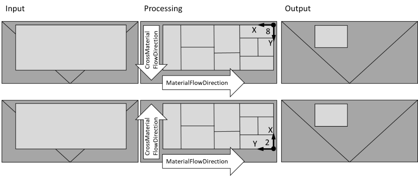
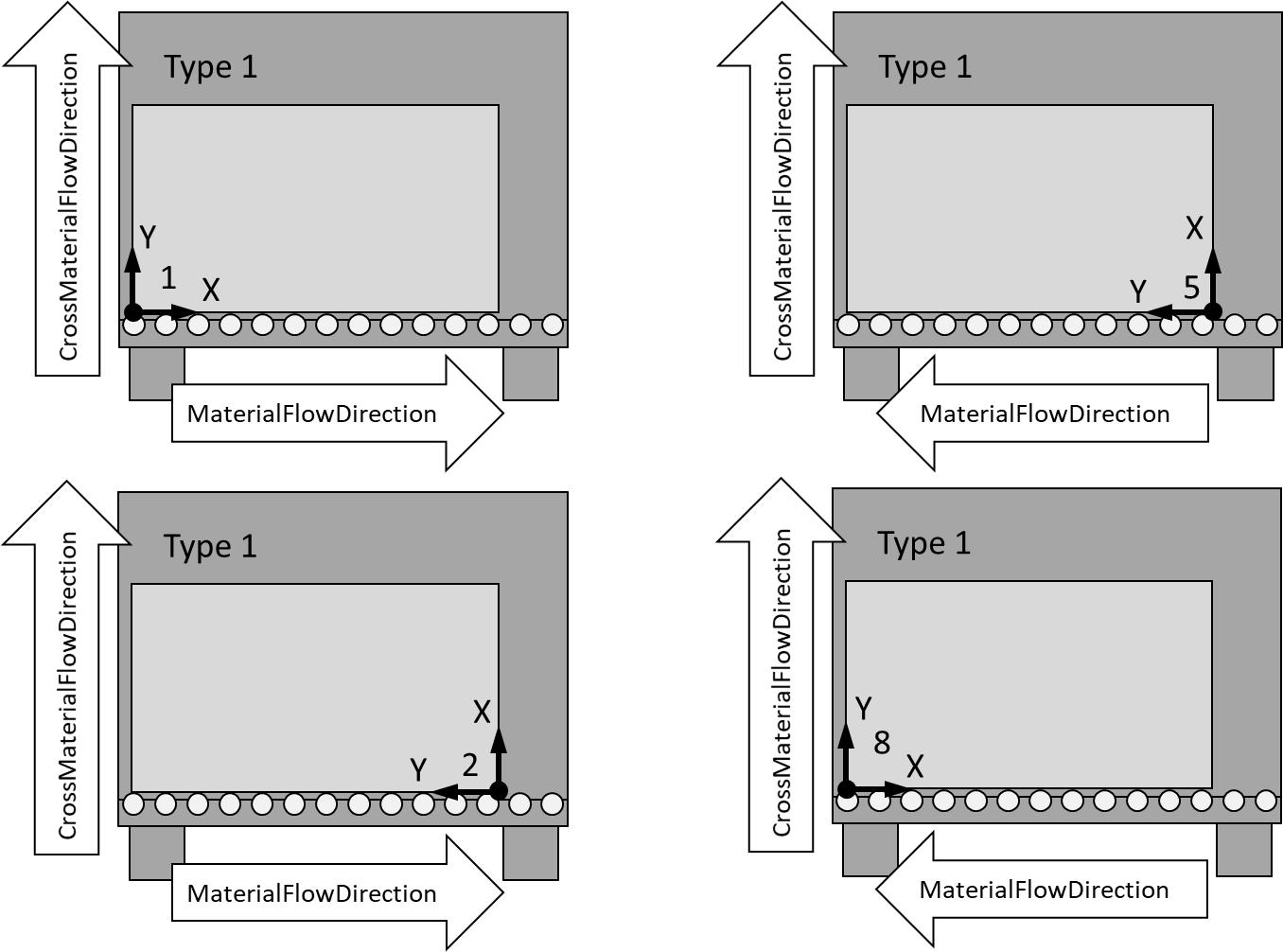
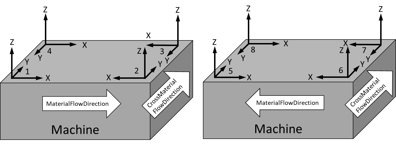
This enumeration specifies the different options in placing the machine processing coordinate systems. The eight different options are shown in Figure 13, as well as some examples in Figure 14 and Figure 15.

Figure 13 – Machine processing coordinate systems

This enumeration is defined in Table 29.

Table 29 – CoordinateSystemEnumeration Items
Name Value Description
Unknown0The CoordinateSystem is unknown.
System11Lefthanded system, X-axis along material flow, Y-axis along cross material flow
System22Righthanded system, X-axis against material flow, Y-axis along cross material flow
System33Lefthanded system, X-axis against material flow, Y-axis against cross material flow
System44Righthanded system, X-axis along material flow, Y-axis against cross material flow
System55Lefthanded system, X-axis against material flow, Y-axis along cross material flow
System66Righthanded system, X-axis along material flow, Y-axis along cross material flow
System77Lefthanded system, X-axis along material flow, Y-axis against cross material flow
System88Righthanded system, X-axis against material flow, Y-axis against cross material flow

Its representation in the AddressSpace is defined in Table 30.

Table 30 – CoordinateSystemEnumeration Definition
Attribute Value
BrowseNameCoordinateSystemEnumeration
IsAbstractFalse
References Node Class BrowseName DataType TypeDefinition Other
Subtype of the Enumeration type defined in OPC 10000-5
0:HasPropertyVariable0:EnumStrings0:LocalizedText[]0:PropertyType
Conformance Units
FlatGlass_CoordinateSystemEnumeration
Figure 14 – Example of glass processing machines for flat lying processing (top view)
Figure 15 – Example of glass processing machines with standing processing (front view)