
1 Scope
This document defines the OPC UA Information Model for the exchange of production and geometry data for the manufacturing of cylindrical cutting tools e.g., endmills, drills and reamers. The interface is to be used for tool grinding machines, laser tool manufacturing, erosion machines, measuring machines and higher-level IT systems. At the same time, existing specifications such as Machinery, Machine Tools or Geometrical Measuring Systems are used in the context for this definition. The description of the geometry data is taken from the VDMA specification series-VDMA 34189 but is only used as a file in the context of this specification.
2 Normative references
The following documents are referred to in the text in such a way that some or all of their content constitutes requirements of this document. For dated references, only the edition cited applies. For undated references, the latest edition of the referenced document (including any amendments and errata) applies.
OPC 10000-1, OPC Unified Architecture - Part 1: Overview and Concepts
http://www.opcfoundation.org/documents/10000-1/
OPC 10000-2, OPC Unified Architecture - Part 2: Security Model
http://www.opcfoundation.org/documents/10000-2/
OPC 10000-3, OPC Unified Architecture - Part 3: Address Space Model
http://www.opcfoundation.org/documents/10000-3/
OPC 10000-4, OPC Unified Architecture - Part 4: Services
http://www.opcfoundation.org/documents/10000-4/
OPC 10000-5, OPC Unified Architecture - Part 5: Information Model
http://www.opcfoundation.org/documents/10000-5/
OPC 10000-6, OPC Unified Architecture - Part 6: Mappings
http://www.opcfoundation.org/documents/10000-6/
OPC 10000-7, OPC Unified Architecture - Part 7: Profiles
http://www.opcfoundation.org/documents/10000-7/
OPC 10000-20, OPC Unified Architecture - Part 20: File Transfer
http://www.opcfoundation.org/documents/10000-20/
OPC 10000-100, OPC Unified Architecture - Part 100: Devices
http://www.opcfoundation.org/documents/10000-100/
OPC 10000-200, OPC Unified Architecture - Part 200: Industrial Automation
http://www.opcfoundation.org/documents/10000-200/
OPC 10031-4, OPC UA for ISA-95 - Part 4: Job Control
http://www.opcfoundation.org/documents/10031-4/
OPC 40001-1, OPC UA for Machinery - Part 1: Basic Building Blocks
http://www.opcfoundation.org/documents/40001-1/
OPC 40001-3, OPC UA for Machinery - Part 3: Job Management
http://www.opcfoundation.org/documents/40001-3
OPC 40001-101, OPC UA for Machinery - Part 101: Result Transfer
http://www.opcfoundation.org/documents/40001-101
OPC 40210, OPC UA for Geometric Measuring Systems
http://www.opcfoundation.org/documents/40210
OPC 40501-1, OPC UA for Machine Tools - Part 1: Monitoring and Job Overview (min. v1.02.0)
http://www.opcfoundation.org/documents/40501-1
3 Terms, definitions, and conventions
3.1 Overview
It is assumed that basic concepts of OPC UA information modelling are understood in this specification. This specification will use these concepts to describe the Cutting Tools Information Model. For the purposes of this document, the terms and definitions given in OPC 10000-1, OPC 10000-3, OPC 10000-4, OPC 10000-5, OPC 10000-7, OPC 10000-20, OPC 10000-100, OPC 10000-200, OPC 10031-4, , OPC 40001-3, OPC 40001-101, OPC 40210, , as well as the following apply.
3.2 OPC UA for Cutting Tools terms
3.2.1 work master
type of work definition that is a template for work to be performed for a job order
[SOURCE: IEC 62264-4:2015(en), 3.1.14]
3.3 Abbreviated terms
| ERP | Enterprise Resource Planning |
| HMI | Human Machine Interface |
| HTTP | Hypertext Transfer Protocol |
| IP | Internet Protocol |
| MES | Manufacturing Execution System |
| PMS | Production Management System |
| TCP | Transmission Control Protocol |
| UML | Unified Modelling Language |
| URI | Uniform Resource Identifier |
| XML | Extensible Markup Language |
3.4 Conventions used in this document
3.4.1 Conventions for Node descriptions
3.4.1.1 Node definitions
Node definitions are specified using tables (see Table 2).
Attributes are defined by providing the Attribute name and a value, or a description of the value.
References are defined by providing the ReferenceType name, the BrowseName of the TargetNode and its NodeClass.
If the TargetNode is a component of the Node being defined in the table, the Attributes of the composed Node are defined in the same row of the table.
The DataType is only specified for Variables; "[<number>]" indicates a single-dimensional array, for multi-dimensional arrays the expression is repeated for each dimension (e.g. [2][3] for a two-dimensional array). For all arrays the ArrayDimensions is set as identified by <number> values. If no <number> is set, the corresponding dimension is set to 0, indicating an unknown size. If no number is provided at all the ArrayDimensions can be omitted. If no brackets are provided, it identifies a scalar DataType and the ValueRank is set to the corresponding value (see OPC 10000-3). In addition, ArrayDimensions is set to null or is omitted. If it can be Any or ScalarOrOneDimension, the value is put into "{<value>}", so either "{Any}" or "{ScalarOrOneDimension}" and the ValueRank is set to the corresponding value (see OPC 10000-3) and the ArrayDimensions is set to null or is omitted. Examples are given in Table 1.
| Notation | DataType | ValueRank | ArrayDimensions | Description |
| 0:Int32 | 0:Int32 | -1 | omitted or null | A scalar Int32. |
| 0:Int32[] | 0:Int32 | 1 | omitted or {0} | Single-dimensional array of Int32 with an unknown size. |
| 0:Int32[][] | 0:Int32 | 2 | omitted or {0,0} | Two-dimensional array of Int32 with unknown sizes for both dimensions. |
| 0:Int32[3][] | 0:Int32 | 2 | {3,0} | Two-dimensional array of Int32 with a size of 3 for the first dimension and an unknown size for the second dimension. |
| 0:Int32[5][3] | 0:Int32 | 2 | {5,3} | Two-dimensional array of Int32 with a size of 5 for the first dimension and a size of 3 for the second dimension. |
| 0:Int32{Any} | 0:Int32 | -2 | omitted or null | An Int32 where it is unknown if it is scalar or array with any number of dimensions. |
| 0:Int32{ScalarOrOneDimension} | 0:Int32 | -3 | omitted or null | An Int32 where it is either a single-dimensional array or a scalar. |
The TypeDefinition is specified for Objects and Variables.
The TypeDefinition column specifies a symbolic name for a NodeId, i.e. the specified Node points with a HasTypeDefinition Reference to the corresponding Node.
The ModellingRule of the referenced component is provided by specifying the symbolic name of the rule in the ModellingRule column. In the AddressSpace, the Node shall use a HasModellingRule Reference to point to the corresponding ModellingRule Object.
If the NodeId of a DataType is provided, the symbolic name of the Node representing the DataType shall be used.
Note that if a symbolic name of a different namespace is used, it is prefixed by the NamespaceIndex (see 3.4.2.2).
Nodes of all other NodeClasses cannot be defined in the same table; therefore, only the used ReferenceType, their NodeClass and their BrowseName are specified. A reference to another part of this document points to their definition. Table 2 illustrates the table. If no components are provided, the DataType, TypeDefinition and ModellingRule columns may be omitted and only a Comment column is introduced to point to the Node definition.
Each Type Node or well-known Instance Node defined shall have one or more ConformanceUnits defined in 10.1 that require the Node to be in the AddressSpace.
The relations between Nodes and ConformanceUnits are defined at the end of the tables defining Nodes, one row per ConformanceUnit. The ConformanceUnits are reflected in the Category element for the Node definition in the UANodeSet (see OPC 10000-6).
The list of ConformanceUnits in the UANodeSet allows Servers to optimize resource consumption by using a list of supported ConformanceUnits to select a subset of the Nodes in an Information Model.
When a Node is selected in this way, all dependencies implied by the References are also selected.
Dependencies exist if the Node is the source of HasTypeDefinition, HasInterface, HasAddIn or any HierarchicalReference. Dependencies also exist if the Node is the target of a HasSubtype Reference. For Variables and VariableTypes, the value of the DataType Attribute is a dependency. For DataType Nodes, any DataTypes referenced in the DataTypeDefinition Attribute are also dependencies.
For additional details see OPC 10000-5.
| Attribute | Value | ||||
| Attribute name | Attribute value. If it is an optional Attribute that is not set "--" will be used. | ||||
| References | NodeClass | BrowseName | DataType | TypeDefinition | Other |
|---|---|---|---|---|---|
| ReferenceType name | NodeClass of the target Node. | BrowseName of the target Node. | DataType of the referenced Node, only applicable for Variables. | TypeDefinition of the referenced Node, only applicable for Variables and Objects. | Additional characteristics of the TargetNode such as the ModellingRule or AccessLevel. |
| NOTE Notes referencing footnotes of the table content. | |||||
| Conformance Units | |||||
|---|---|---|---|---|---|
| Name of ConformanceUnit, one row per ConformanceUnit |
Components of Nodes can be complex that is containing components by themselves. The TypeDefinition, NodeClass and DataType can be derived from the type definitions, and the symbolic name can be created as defined in 3.4.3.1. Therefore, those containing components are not explicitly specified; they are implicitly specified by the type definitions.
The Other column defines additional characteristics of the Node. Examples of characteristics that can appear in this column are show in Table 3.
| Name | Short Name | Description |
| 0:Mandatory | M | The Node has the Mandatory ModellingRule. |
| 0:Optional | O | The Node has the Optional ModellingRule. |
| 0:MandatoryPlaceholder | MP | The Node has the MandatoryPlaceholder ModellingRule. |
| 0:OptionalPlaceholder | OP | The Node has the OptionalPlaceholder ModellingRule. |
| ReadOnly | RO | The Node AccessLevel has the CurrentRead bit set but not the CurrentWrite bit. |
| ReadWrite | RW | The Node AccessLevel has the CurrentRead and CurrentWrite bits set. |
| WriteOnly | WO | The Node AccessLevel has the CurrentWrite bit set but not the CurrentRead bit. |
If multiple characteristics are defined, they are separated by commas. The name or the short name may be used.
3.4.1.2 Additional References
To provide information about additional References, the format as shown in Table 4 is used.
| SourceBrowsePath | Reference Type | Is Forward | TargetBrowsePath |
| SourceBrowsePath is always relative to the TypeDefinition. Multiple elements are defined as separate rows of a nested table. | ReferenceType name | True = forward Reference | TargetBrowsePath points to another Node, which can be a well-known instance or a TypeDefinition. You can use BrowsePaths here as well, which is either relative to the TypeDefinition or absolute. If absolute, the first entry needs to refer to a type or well-known instance, uniquely identified within a namespace by the BrowseName. |
References can be to any other Node.
3.4.1.3 Additional sub-components
To provide information about sub-components, the format as shown in Table 5 is used.
| BrowsePath | Reference | NodeClass | BrowseName | DataType | TypeDefinition | Others |
| BrowsePath is always relative to the TypeDefinition. Multiple elements are defined as separate rows of a nested table | NOTE Same as for Table 2 | |||||
3.4.1.4 Additional Attribute values
The type definition table provides columns to specify the values for required Node Attributes for InstanceDeclarations. To provide information about additional Attributes, the format as shown in Table 6 is used.
| BrowsePath | <Attribute name> Attribute |
| BrowsePath is always relative to the TypeDefinition. Multiple elements are defined as separate rows of a nested table | The values of attributes are converted to text by adapting the reversible JSON encoding rules defined in OPC 10000-6. If the JSON encoding of a value is a JSON string or a JSON number then that value is entered in the value field. Double quotes are not included. If the DataType includes a NamespaceIndex (QualifiedNames, NodeIds or ExpandedNodeIds) then the notation used for BrowseNames is used. If the value is an Enumeration the name of the enumeration value is entered. If the value is a Structure then a sequence of name and value pairs is entered. Each pair is followed by a newline. The name is followed by a colon. The names are the names of the fields in the DataTypeDefinition. If the value is an array of non-structures then a sequence of values is entered where each value is followed by a newline. If the value is an array of Structures or a Structure with fields that are arrays or with nested Structures then the complete JSON array or JSON object is entered. |
There can be multiple columns to define more than one Attribute.
3.4.2 NodeIds and BrowseNames
3.4.2.1 NodeIds
The NodeIds of all Nodes described in this standard are only symbolic names. Annex A defines the actual NodeIds.
The symbolic name of each Node defined in this document is its BrowseName, or, when it is part of another Node, the BrowseName of the other Node, a ".", and the BrowseName of itself. In this case "part of" means that the whole has a HasProperty or HasComponent Reference to its part. Since all Nodes not being part of another Node have a unique name in this document, the symbolic name is unique.
The NamespaceUri for all NodeIds defined in this document is defined in Annex A. The NamespaceIndex for this NamespaceUri is vendor-specific and depends on the position of the NamespaceUri in the server namespace table.
Note that this document not only defines concrete Nodes, but also requires that some Nodes shall be generated, for example one for each Session running on the Server. The NodeIds of those Nodes are Server-specific, including the namespace. But the NamespaceIndex of those Nodes cannot be the NamespaceIndex used for the Nodes defined in this document, because they are not defined by this document but generated by the Server.
3.4.2.2 BrowseNames
The text part of the BrowseNames for all Nodes defined in this document is specified in the tables defining the Nodes. The NamespaceUri for all BrowseNames defined in this document is defined in 11.2.
For InstanceDeclarations of NodeClass Object and Variable that are placeholders (OptionalPlaceholder and MandatoryPlaceholder ModellingRule), the BrowseName and the DisplayName are enclosed in angle brackets (<>) as recommended in OPC 10000-3.
If the BrowseName is not defined by this document, a namespace index prefix is added to the BrowseName (e.g., prefix '0' leading to '0:EngineeringUnits' or prefix '2' leading to '2:DeviceRevision'). This is typically necessary if a Property of another specification is overwritten or used in the OPC UA types defined in this document. Table 30 provides a list of namespaces and their indexes as used in this document.
3.4.3 Common Attributes
3.4.3.1 General
The Attributes of Nodes, their DataTypes and descriptions are defined in OPC 10000-3. Attributes not marked as optional are mandatory and shall be provided by a Server. The following tables define if the Attribute value is defined by this specification or if it is server-specific.
For all Nodes specified in this specification, the Attributes named in Table 7 shall be set as specified in the table.
| Attribute | Value |
| DisplayName | The DisplayName is a LocalizedText. Each server shall provide the DisplayName identical to the BrowseName of the Node for the LocaleId "en". Whether the server provides translated names for other LocaleIds is server-specific. |
| Description | Optionally a server-specific description is provided. |
| NodeClass | Shall reflect the NodeClass of the Node. |
| NodeId | The NodeId is described by BrowseNames as defined in 3.4.2.1. |
| WriteMask | Optionally the WriteMask Attribute can be provided. If the WriteMask Attribute is provided, it shall set all non-server-specific Attributes to not writable. For example, the Description Attribute may be set to writable since a Server may provide a server-specific description for the Node. The NodeId shall not be writable, because it is defined for each Node in this specification. |
| UserWriteMask | Optionally the UserWriteMask Attribute can be provided. The same rules as for the WriteMask Attribute apply. |
| RolePermissions | Optionally server-specific role permissions can be provided. |
| UserRolePermissions | Optionally the role permissions of the current Session can be provided. The value is server-specifc and depend on the RolePermissions Attribute (if provided) and the current Session. |
| AccessRestrictions | Optionally server-specific access restrictions can be provided. |
3.4.3.2 Objects
For all Objects specified in this specification, the Attributes named in Table 8 shall be set as specified in the table. The definitions for the Attributes can be found in OPC 10000-3.
| Attribute | Value |
| EventNotifier | Whether the Node can be used to subscribe to Events or not is server-specific. |
3.4.3.3 Variables
For all Variables specified in this specification, the Attributes named in Table 9 shall be set as specified in the table. The definitions for the Attributes can be found in OPC 10000-3.
| Attribute | Value |
| MinimumSamplingInterval | Optionally, a server-specific minimum sampling interval is provided. |
| AccessLevel | The access level for Variables used for type definitions is server-specific, for all other Variables defined in this specification, the access level shall allow reading; other settings are server-specific. |
| UserAccessLevel | The value for the UserAccessLevel Attribute is server-specific. It is assumed that all Variables can be accessed by at least one user. |
| Value | For Variables used as InstanceDeclarations, the value is server-specific; otherwise it shall represent the value described in the text. |
| ArrayDimensions | If the ValueRank does not identify an array of a specific dimension (i.e. ValueRank <= 0) the ArrayDimensions can either be set to null or the Attribute is missing. This behaviour is server-specific. If the ValueRank specifies an array of a specific dimension (i.e. ValueRank > 0) then the ArrayDimensions Attribute shall be specified in the table defining the Variable. |
| Historizing | The value for the Historizing Attribute is server-specific. |
| AccessLevelEx | If the AccessLevelEx Attribute is provided, it shall have the bits 8, 9, and 10 set to 0, meaning that read and write operations on an individual Variable are atomic, and arrays can be partly written. |
3.4.3.4 VariableTypes
For all VariableTypes specified in this specification, the Attributes named in Table 10 shall be set as specified in the table. The definitions for the Attributes can be found in OPC 10000-3.
| Attributes | Value |
| Value | Optionally a server-specific default value can be provided. |
| ArrayDimensions | If the ValueRank does not identify an array of a specific dimension (i.e. ValueRank <= 0) the ArrayDimensions can either be set to null or the Attribute is missing. This behaviour is server-specific. If the ValueRank specifies an array of a specific dimension (i.e. ValueRank > 0) then the ArrayDimensions Attribute shall be specified in the table defining the VariableType. |
3.4.3.5 Methods
For all Methods specified in this specification, the Attributes named in Table 11 shall be set as specified in the table. The definitions for the Attributes can be found in OPC 10000-3.
| Attributes | Value |
| Executable | All Methods defined in this specification shall be executable (Executable Attribute set to "True"), unless it is defined differently in the Method definition. |
| UserExecutable | The value of the UserExecutable Attribute is server-specific. It is assumed that all Methods can be executed by at least one user. |
3.4.4 Structures
OPC 10000-3 differentiates between different kinds of Structures. The following conventions explain, how these Structures shall be defined.
The first kind are Structures without optional fields where none of the fields allows subtype (except fields with abstract DataTypes). Its definition is in Table 12.
| Name | Type | Description |
| <someStructure> | structure | Subtype of <someParentStructure> defined in … |
SP1 | 0:Byte[] | Setpoint 1 |
SP2 | 0:Byte[] | Setpoint 2 |
The second kind are Structures with optional fields where none of the fields allows subtypes (except fields with abstract DataTypes). Its definition is in Table 13.
Structures with fields that are optional have an "Optional" column. Fields that are optional have True set, otherwise False.
| Name | Type | Description | Optional |
| <someStructure> | structure | Subtype of <someParentStructure> defined in … | |
SP1 | 0:Byte[] | Setpoint 1 | False |
SP2 | 0:Byte[] | Setpoint 2 | True |
The third kind are Structures without optional fields where one or more of the fields allow subtypes. Its definition is in Table 14.
Structures with fields that allow subtypes have an "Allow Subtypes" column. Fields that allow subtypes have True set, otherwise False. Fields with abstract DataTypes can always be subtyped.
| Name | Type | Description | Allow SubTypes |
| <someStructure> | structure | Subtype of <someParentStructure> defined in … | |
SP1 | 0:Byte[] | Setpoint 1 | False |
Allow Subtypes | 0:ByteString | Some Bytestring | True |
4 General information to Cutting Tools and OPC UA
4.1 Introduction to Cutting Tools
To cut solid metal and other hard materials like wood and hard plastics a machine tool or woodworking machine needs cutting tools. These cutting tools are typically ground from cylindrical solid carbide or high-speed steel blanks. To cut sheet metal on the other hand punching or shearing tools are used. This specification deals with the manufacturing process of cylindrical cutting tools like end mills, drills, reamers, and thread cutters as well in the future with grinding wheels and wheelsets used to manufacture these cutting tools and the following measurement process. It implicitly also allows the use for tool remanufacturing, where expensive tools are measured and then reground to refurbish the geometrical properties.
The interface is to be used for tool grinding machines, laser tool manufacturing, erosion machines, measuring machines and higher-level IT systems. This specification reuses and inherits many type definitions from other companion specifications, as many use cases are common for other grinding and measuring machines as well as using the standardized job management and other feature from the OPC UA for Machinery companion specification.
Therefore, we are mainly focusing on the unique use cases describe in 5 and the defined TypeDefinitions are instance declaration for the use in this sector.
The typical workflow in the tool manufacturing process is the following.
Starting with the design and definition of a cutting tool in a CAD/CAM tool chain, the geometrical properties are defined as well as the necessary NC tool path calculation happens. Furthermore, the grinding wheel geometry and needed grinding wheelset definition is done. All these prepared definitions are then stored in the standardized format defined by specification VDMA 34189. Together with the production plan, how many and when these are to be produced, it is prepared and send to the tool manufacturing machine via the OPC UA interface defined by this companion specification.
After production of the first cutting tool or workpiece, the nominal geometry is transferred to the measuring machine with the workpiece for measuring. The workpiece is then measured, and the actual geometry is stored in the same format or file defined above. The transfer of the file and the job happens also by this standardized interface. This result file is then available for the higher-level IT system for quality assurance and control as well as for the manufacturing machine to calculate grinding path corrections to ensure the required geometry.
Possible system architectures how the OPC UA application might be deployed are described in Annex B.
4.2 Introduction to OPC Unified Architecture
4.2.1 What is OPC UA?
OPC UA is an open and royalty free set of standards designed as a universal communication protocol. While there are numerous communication solutions available, OPC UA has key advantages:
A state of art security model (see OPC 10000-2).
A fault tolerant communication protocol.
An information modelling framework that allows application developers to represent their data in a way that makes sense to them.
OPC UA has a broad scope which delivers for economies of scale for application developers. This means that a larger number of high-quality applications at a reasonable cost are available. When combined with semantic models such as Cutting Tools, OPC UA makes it easier for end users to access data via generic commercial applications.
The OPC UA model is scalable from small devices to ERP systems. OPC UA Servers process information locally and then provide that data in a consistent format to any application requesting data - ERP, MES, PMS, Maintenance Systems, HMI, Smartphone or a standard Browser, for examples. For a more complete overview see OPC 10000-1.
4.2.2 Basics of OPC UA
As an open standard, OPC UA is based on standard internet technologies, like TCP/IP, HTTP, Web Sockets.
As an extensible standard, OPC UA provides a set of Services (see OPC 10000-4) and a basic information model framework. This framework provides an easy manner for creating and exposing vendor defined information in a standard way. More importantly all OPC UA Clients are expected to be able to discover and use vendor-defined information. This means OPC UA users can benefit from the economies of scale that come with generic visualization and historian applications. This specification is an example of an OPC UA Information Model designed to meet the needs of developers and users.
OPC UA Clients can be any consumer of data from another device on the network to browser based thin clients and ERP systems. The full scope of OPC UA applications is shown in Figure 1.

OPC UA provides a robust and reliable communication infrastructure having mechanisms for handling lost messages, failover, heartbeat, etc. With its binary encoded data, it offers a high-performing data exchange solution. Security is built into OPC UA as security requirements become more and more important especially since environments are connected to the office network or the internet and attackers are starting to focus on automation systems.
4.2.3 Information modelling in OPC UA
4.2.3.1 Concepts
OPC UA provides a framework that can be used to represent complex information as Objects in an AddressSpace which can be accessed with standard services. These Objects consist of Nodes connected by References. Different classes of Nodes convey different semantics. For example, a Variable Node represents a value that can be read or written. The Variable Node has an associated DataType that can define the actual value, such as a string, float, structure etc. It can also describe the Variable value as a variant. A Method Node represents a function that can be called. Every Node has a number of Attributes including a unique identifier called a NodeId and non-localized name called as BrowseName. An Object representing a 'Reservation' is shown in Figure 2.

Object and Variable Nodes represent instances and they always reference a TypeDefinition (ObjectType or VariableType) Node which describes their semantics and structure. Figure 3 illustrates the relationship between an instance and its TypeDefinition.
The type Nodes are templates that define all of the children that can be present in an instance of the type. In the example in Figure 3 the PersonType ObjectType defines two children: First Name and Last Name. All instances of PersonType are expected to have the same children with the same BrowseNames. Within a type the BrowseNames uniquely identify the children. This means Client applications can be designed to search for children based on the BrowseNames from the type instead of NodeIds. This eliminates the need for manual reconfiguration of systems if a Client uses types that multiple Servers implement.
OPC UA also supports the concept of sub-typing. This allows a modeller to take an existing type and extend it. There are rules regarding sub-typing defined in OPC 10000-3, but in general they allow the extension of a given type or the restriction of a DataType. For example, the modeller may decide that the existing ObjectType in some cases needs an additional Variable. The modeller can create a subtype of the ObjectType and add the Variable. A Client that is expecting the parent type can treat the new type as if it was of the parent type. Regarding DataTypes, subtypes can only restrict. If a Variable is defined to have a numeric value, a sub type could restrict it to a float.

References allow Nodes to be connected in ways that describe their relationships. All References have a ReferenceType that specifies the semantics of the relationship. References can be hierarchical or non-hierarchical. Hierarchical references are used to create the structure of Objects and Variables. Non-hierarchical are used to create arbitrary associations. Applications can define their own ReferenceType by creating subtypes of an existing ReferenceType. Subtypes inherit the semantics of the parent but may add additional restrictions. Figure 4 depicts several References, connecting different Objects.

The figures above use a notation that was developed for the OPC UA specification. The notation is summarized in Figure 5. UML representations can also be used; however, the OPC UA notation is less ambiguous because there is a direct mapping from the elements in the figures to Nodes in the AddressSpace of an OPC UA Server.

A complete description of the different types of Nodes and References can be found in OPC 10000-3 and the base structure is described in OPC 10000-5.
OPC UA specification defines a very wide range of functionality in its basic information model. It is not required that all Clients or Servers support all functionality in the OPC UA specifications. OPC UA includes the concept of Profiles, which segment the functionality into testable certifiable units. This allows the definition of functional subsets (that are expected to be implemented) within a companion specification. The Profiles do not restrict functionality, but generate requirements for a minimum set of functionalities (see OPC 10000-7)
4.2.3.2 Namespaces
OPC UA allows information from many different sources to be combined into a single coherent AddressSpace. Namespaces are used to make this possible by eliminating naming and id conflicts between information from different sources. Each namespace in OPC UA has a globally unique string called a NamespaceUri which identifies a naming authority, and a locally unique integer called a NamespaceIndex, which is an index into the Server's table of NamespaceUris. The NamespaceIndex is unique only within the context of a Session between an OPC UA Client and an OPC UA Server- the NamespaceIndex can change between Sessions and still identify the same item even though the NamespaceUri's location in the table has changed. The Services defined for OPC UA use the NamespaceIndex to specify the Namespace for qualified values.
There are two types of structured values in OPC UA that are qualified with NamespaceIndexes: NodeIds and QualifiedNames. NodeIds are locally unique (and sometimes globally unique) identifiers for Nodes. The same globally unique NodeId can be used as the identifier in a node in many Servers - the node's instance data may vary but its semantic meaning is the same regardless of the Server it appears in. This means Clients can have built-in knowledge of of what the data means in these Nodes. OPC UA Information Models generally define globally unique NodeIds for the TypeDefinitions defined by the Information Model.
QualifiedNames are non-localized names qualified with a Namespace. They are used for the BrowseNames of Nodes and allow the same names to be used by different information models without conflict. TypeDefinitions are not allowed to have children with duplicate BrowseNames; however, instances do not have that restriction.
4.2.3.3 Companion Specifications
An OPC UA companion specification for an industry specific vertical market describes an Information Model by defining ObjectTypes, VariableTypes, DataTypes and ReferenceTypes that represent the concepts used in the vertical market, and potentially also well-defined Objects as entry points into the AddressSpace.
5 Use cases
5.1 "Closed loop" geometrical data exchange for cutting tools manufacturing between tool manufacturing and tool measuring machines and tool control systems
To facilitate the production process of cutting tools, a tool control system creates the geometrical data to manufacture workpieces (cutting tools) on a tool manufacturing machine. Afterwards for quality control these workpieces are measured on measuring machines and the deviations need to be taken into account for further production of tools.
This interface defines how this exchange of geometrical data between tool control system, production and measuring machines happens. Implementation of this interface on all relevant systems will enable a highly optimized and largely automated processing of this data.
5.2 Geometrical information exchange for grinding wheels from grinding machines and measuring machines
Getting and setting grinding wheel geometrical data from a measurement machine and a grinding machine to enable exchange to a tool management system.
Grinding wheel set is measured offline on a "setting machine" and added to the grinding machine at a process change over.
Grinding wheel set geometrical information needs to be transferred to and from the machine to enable a factory wide tool management.
Grinding wheel sets can be measured inline on the grinding machine as well and these measurements need to update the overall geometry of the grinding wheel set.
6 Cutting Tools Information Model overview
This section introduces the "OPC UA Information Model for Cutting Tools".
For the Cutting Tools use cases, subtypes of the information models and OPC 40210 are used for the machines and the implementation of the necessary objects are specified and necessary attributes are added.
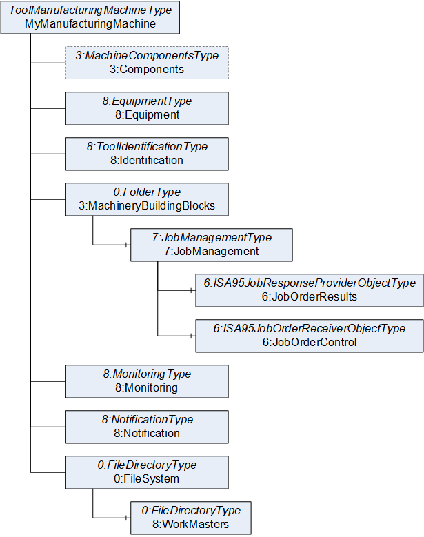
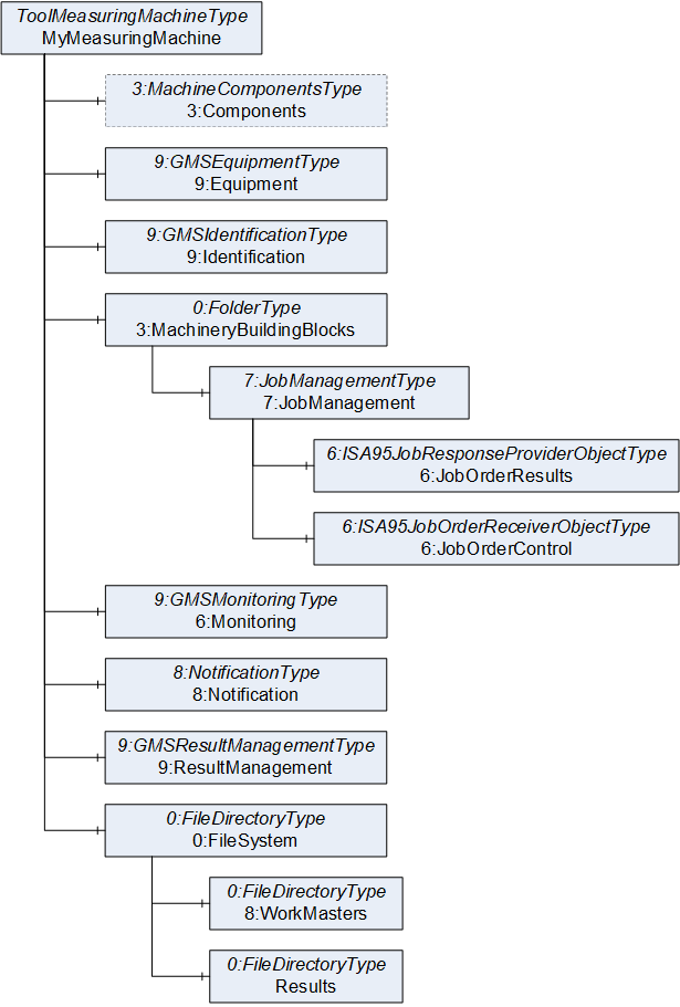
The ToolManufacturingMachineType (subtype of 8:MachineToolType) is used for the implementation of the tool manufacturing machine, as shown in Figure 6 and the ToolMeasuringMachineType (subtype of 9:GMSType) is used for the measuring machine as shown in Figure 7.
For job management the 7:JobManagementType of OPC 40001-3 is used as inherited from version 1.02.
For data exchange, a standardized 0:FileSystem shall be used.
Result management as defined by OPC 40001-101 is used within the measuring machine to notify the tool manufacturing machine about finished measurements.
The files describing the cutting tools geometry are to be stored in 8:WorkMasters file directory. These files can be stored and retrieved on the machine using the methods of 0:FileDirectoryType defined by OPC 10000-20. These work masters shall be referenced within the 6:WorkMaster of the 7:JobOrderControl and in the structure of the 6:ISA95JobOrderAndStateDataType describing a job in the 6:JobOrderList.
Within the measuring machine, the measurement data of the completed workpieces shall be stored in the Results folder of the 0:FileSystem. To ensure that the processing machine and higher level systems find the appropriate data, reference shall be made to this in the 9:GMSResultManagementType under 5:Results.
7 OPC UA ObjectTypes
7.1 ToolManufacturingMachineType ObjectType Definition
The ToolManufacturingMachineType represents the tool manufacturing machine interface of the information model. It is the entry point to the OPC UA interface of a tool manufacturing machine. It gives a basic structure to the interface. An instance of this type aggregates all information related to one system.
All instances of ToolManufacturingMachineType have to be referenced from the 3:Machines node defined in . At least one ToolManufacturingMachineType instance shall be present to qualify for any manufacturing machine profile of OPC 40504.
The ToolManufacturingMachineType and is formally defined in Table 15.
| Attribute | Value | ||||
| BrowseName | ToolManufacturingMachineType | ||||
| IsAbstract | False | ||||
| References | Node Class | BrowseName | DataType | TypeDefinition | Other |
|---|---|---|---|---|---|
| Subtype of the 8:MachineToolType defined in i.e. inheriting the InstanceDeclarations of that Node. | |||||
| 0:HasComponent | Object | 3:MachineryBuildingBlocks | 0:FolderType | M | |
| 0:HasComponent | Object | 0:FileSystem | 0:FileDirectoryType | M | |
| Conformance Units | |||||
|---|---|---|---|---|---|
| CuttingTool ToolManufacturingMachineType | |||||
| CuttingTool FileSystem ToolManufacturingMachine |
The components of the ToolManufacturingMachineType have additional subcomponents which are defined in Table 16.
| Source Path | Reference | NodeClass | BrowseName | DataType | TypeDefinition | Others |
| 0:FileSystem | 0:HasComponent | Object | 8:WorkMasters | 0:FileDirectoryType | O | |
| 3:MachineryBuildingBlocks | 0:HasAddIn | Object | 7:JobManagement | 7:JobManagementType | M |
The 0:FileSystem is the root of all file directories of the OPC UA and the underlying machine.
7.2 ToolMeasuringMachineType ObjectType Definition
The ToolMeasuringMachineType represents the measuring machine interface of the information model. It is the entry point to the OPC UA interface of a Tool Measuring Machine. It gives a basic structure to the interface. An instance of this type aggregates all information related to one system.
All instances of ToolMeasuringMachineType have to be referenced from the 3:Machines node defined in . At least one ToolMeasuringMachineType instance shall be present to qualify for any measuring machine profile of OPC 40504.
The ToolMeasuringMachineType is formally defined in Table 17.
| Attribute | Value | ||||
| BrowseName | ToolMeasuringMachineType | ||||
| IsAbstract | False | ||||
| References | Node Class | BrowseName | DataType | TypeDefinition | Other |
|---|---|---|---|---|---|
| Subtype of the 9:GMSType defined in OPC 40210 i.e. inheriting the InstanceDeclarations of that Node. | |||||
| 0:HasComponent | Object | 3:MachineryBuildingBlocks | 0:FolderType | M | |
| 0:HasComponent | Object | 0:FileSystem | 0:FileDirectoryType | M | |
| Conformance Units | |||||
|---|---|---|---|---|---|
| CuttingTool ToolMeasuringMachineType | |||||
| CuttingTool FileSystem ToolMeasuringMachine |
The components of the ToolMeasuringMachineType have additional subcomponents which are defined in Table 18.
| Source Path | Reference | NodeClass | BrowseName | DataType | TypeDefinition | Others |
| 0:FileSystem | 0:HasComponent | Object | 8:WorkMasters | 0:FileDirectoryType | O | |
| 0:FileSystem | 0:HasComponent | Object | Results | 0:FileDirectoryType | O | |
| 3:MachineryBuildingBlocks | 0:HasAddIn | Object | 7:JobManagement | 7:JobManagementType | M |
The 0:FileSystem is the root of all file directories of the OPC UA and the underlying machine.
7.3 CuttingToolFileType ObjectType Definition
The CuttingToolFileType provides metadata of the standardized file that it represents on the OPC UA server.
It is formally defined in Table 19.
| Attribute | Value | ||||
| BrowseName | CuttingToolFileType | ||||
| IsAbstract | False | ||||
| References | Node Class | BrowseName | DataType | TypeDefinition | Other |
|---|---|---|---|---|---|
| Subtype of the 0:FileType defined in OPC 10000-20 i.e. inheriting the InstanceDeclarations of that Node. | |||||
| 0:HasProperty | Variable | FileFormat | FileFormatDataType | 0:PropertyType | M |
| Conformance Units | |||||
|---|---|---|---|---|---|
| CuttingTool CuttingToolFileType |
The property Version shall be filled with the semantic version of the XML definition standardized by the VDMA specification series 34189.
8 Additional Information about the Job Management
8.1 Overview
OPC 10031-4 defines mechanisms to add job order information using the 6:ISA95JobOrderDataType and mechanisms getting the result or current status of the job order using the 6:ISA95JobResponseDataType. Both DataTypes define arrays of properties of a job order: general, personal, equipment, physical assets, and material. The 6:ISA95JobOrderDataType uses the general properties to describe the job order and the other properties to define the requirements, whereas the 6:ISA95JobResponseDataType uses the general properties to describe the output and the other properties to provide the information what has been used.
OPC 40001-3 UA for Machinery Job Management standardizes some of those parameters, which are application-specific from the view of OPC 10031-4.
The guidelines and extensions specified in this section are designed to complement the foundational models, providing a structured framework for implementation. The optional elements (e.g., fields or parameters) of the OPC 10031-4 or OPC 40001-3 may be used as defined.
8.2 Management of WorkMaster and WorkMaster files
The WorkMasterID field of the 6:ISA95JobOrderDataType contains the information about the work master (e.g., the cutting tool file). The field ID is an identification of the work master. This should be used to identify a work master across different OPC UA Servers and must be unique in its scope (e.g., company unique).
This specification uses the 0:FileSystem folder to manage (e.g., store/retrieve files) the work master files on the server. To connect the WorkMasterID with the file additional predefined key-value pairs for 6:ISA95WorkMasterDataType.Parameter are defined in Table 20.
| ID | DataType of Value | Description | EngineeringUnits | Subparameters |
|---|---|---|---|---|
| LocalPath | String | Contains the file path on the OPC UA server. This must be identical with the relative path of the BrowsePath. | - | - |
| FileNodeId | 0:NodeId | Contains the NodeId of the object of the file. | - | - |
| FileFormat | FileFormatDataType | Defines the file format of the work master file. This is used to ensure compatibility between the work master and the machine. | - | - |
9 OPC UA DataTypes
9.1 FileFormatDataType
A file format describes the syntax and semantic of a document. This structure contains the information about a file format. The structure is defined in Table 21.
| Name | Type | Description |
|---|---|---|
| FileFormatDataType | structure | Subtype of Structure defined in OPC 10000-5 |
Name | 0:String | The Name of the File. The following strings are examples for a File Name: "SquareEndmill", "GrindingProgram", "MeasuringProgram" |
FileExtension | 0:String | Is the identifier specified as a suffix to the name of a file. The FileExtension has a leading dot. So, the FileExtension should be look like ".nc", ".json", ".gdx" |
Version | 0:SemanticVersionString | Version of the File. Syntax is major.minor[.build] (example 2.1 or 2.3.2) |
Its representation in the AddressSpace is defined in Table 22.
| Attribute | Value | |||||
| BrowseName | FileFormatDataType | |||||
| IsAbstract | False | |||||
| References | NodeClass | BrowseName | DataType | TypeDefinition | Other | |
|---|---|---|---|---|---|---|
| Subtype of Structure defined in OPC 10000-3. | ||||||
| Conformance Units | ||||||
|---|---|---|---|---|---|---|
| CuttingTool CuttingToolFileType |
10 Profiles and ConformanceUnits
10.1 Conformance Units
This chapter defines the corresponding Conformance Units for the OPC UA Information Model for Cutting Tools.
| Category | Title | Description |
| Server | CuttingTool ToolManufacturingMachineType | All TypeDefinition nodes declared as mandatory in the ToolManufacturingMachineType are available in the AddressSpace. The nodes declared as optional may be included in the AddressSpace. At least on instance of a ToolManufacturingMachineType is available in the AddressSpace. |
| Server | CuttingTool ToolMeasuringMachineType | All nodes declared as mandatory in the ToolMeasuringMachineType are available in the AddressSpace. The nodes declared as optional may be included in the AddressSpace. At least on instance of a ToolMeasuringMachineType is available in the AddressSpace. |
| Server | CuttingTool FileSystem ToolManufacturingMachine | The tool manufacturing machine instance exposes with the WorkMasters FileDirectoryType instance the underlying FileSystem for reading and writing. |
| Server | CuttingTool FileSystem ToolMeasuringMachine | The tool measuring machine instance exposes with the WorkMasters and Results FileDirectoryType instances the underlying FileSystem for reading and writing. |
| Server | CuttingTool CuttingToolFileType | All nodes declared as mandatory in the CuttingToolFileType are available in the AddressSpace. The nodes declared as optional may be included in the AddressSpace. |
10.2 Profiles
10.2.1 Profile list
Table 24 lists all Profiles defined in this document and defines their URIs.
| Profile | URI |
| CuttingTool Manufacturing Machine Basic Server Profile | http://opcfoundation.org/UA-Profile/CuttingTool/Server/ManufacturingMachineBasic |
| CuttingTool Measuring Machine Basic Server Profile | http://opcfoundation.org/UA-Profile/CuttingTool/Server/MeasuringMachineBasic |
| CuttingTool Client Facet | http://opcfoundation.org/UA-Profile/CuttingTool/Client/Basic |
10.2.2 Server Facets
10.2.2.1 Overview
The following sections specify the Facets available for Servers that implement the Cutting Tools companion specification. Each section defines and describes a Facet or Profile.
10.2.2.2 CuttingTool Manufacturing Machine Basic Server Profile
Table 25 defines a Profile that describes the minimum required content and address space functionality any CuttingTool server implemented on a tool manufacturing machine shall at least provide.
| Group | Conformance Unit / Profile Title | Mandatory / Optional |
| Profile | 8:MachineTool Basic Server Profile | M |
| Profile | 8:MachineTool Job Management Server Profile | M |
| MachineTool | 8:MachineTool FileSystem | M |
| CuttingTool | CuttingTool ToolManufacturingMachineType | M |
| CuttingTool | CuttingTool FileSystem ToolManufacturingMachine | O |
| CuttingTool | CuttingTool CuttingToolFileType | O |
10.2.2.3 CuttingTool Measuring Machine Basic Server Profile
Table 26 defines a Profile that describes the minimum required content and address space functionality any CuttingTool server implemented on a measuring machine shall at least provide.
| Group | Conformance Unit / Profile Title | Mandatory / Optional |
| Profile | 9:GMS Basic Server Profile | M |
| Profile | 8:MachineTool Job Management Server Profile | M |
| MachineTool | 8:MachineTool FileSystem | M |
| CuttingTool | CuttingTool ToolMeasuringMachineType | M |
| CuttingTool | CuttingTool FileSystem ToolMeasuringMachine | O |
| CuttingTool | CuttingTool CuttingToolFileType | O |
10.2.3 Client Facets
10.2.3.1 Overview
The following tables specify the Facets available for Clients that implement the Cutting Tools companion specification.
10.2.3.2 CuttingTool Basic Client Facet
Table 27 defines a Facet that describes the base characteristics for all OPC UA Clients that make use of this companion specification. Additional Profiles will define support for various information models that are part of this document.
| Group | Conformance Unit / Profile Title | Mandatory / Optional |
| Profile | 6:ISA-95 Job Order Receiver Client V2 Facet | M |
| Profile | 6:ISA-95 Job Order Response Provider Client V2 Facet | M |
| CuttingTool | CuttingTool CuttingToolFileType | M |
11 Namespaces
11.1 Namespace Metadata
Table 28 defines the namespace metadata for this document. The Object is used to provide version information for the namespace and an indication about static Nodes. Static Nodes are identical for all Attributes in all Servers, including the Value Attribute. See OPC 10000-5 for more details.
The information is provided as Object of type NamespaceMetadataType. This Object is a component of the Namespaces Object that is part of the Server Object. The NamespaceMetadataType ObjectType and its Properties are defined in OPC 10000-5.
The version information is also provided as part of the ModelTableEntry in the UANodeSet XML file. The UANodeSet XML schema is defined in OPC 10000-6.
| Attribute | Value | ||
| BrowseName | http://opcfoundation.org/UA/CuttingTool/ | ||
| Property | DataType | Value | |
|---|---|---|---|
| NamespaceUri | String | http://opcfoundation.org/UA/CuttingTool/ | |
| NamespaceVersion | String | 1.0.0 | |
| NamespacePublicationDate | DateTime | 2024-11-01 | |
| IsNamespaceSubset | Boolean | False | |
| StaticNodeIdTypes | IdType [] | 0 | |
| StaticNumericNodeIdRange | NumericRange [] | ||
| StaticStringNodeIdPattern | String | ||
11.2 Handling of OPC UA Namespaces
Namespaces are used by OPC UA to create unique identifiers across different naming authorities. The Attributes NodeId and BrowseName are identifiers. A Node in the UA AddressSpace is unambiguously identified using a NodeId. Unlike NodeIds, the BrowseName cannot be used to unambiguously identify a Node. Different Nodes may have the same BrowseName. They are used to build a browse path between two Nodes or to define a standard Property.
Servers may often choose to use the same namespace for the NodeId and the BrowseName. However, if they want to provide a standard Property, its BrowseName shall have the namespace of the standards body although the namespace of the NodeId reflects something else, for example the EngineeringUnits Property. All NodeIds of Nodes not defined in this document shall not use the standard namespaces.
Table 29 provides a list of mandatory and optional namespaces used in a Cutting Tools OPC UA Server.
| NamespaceURI | Description | Use |
| http://opcfoundation.org/UA/ | Namespace for NodeIds and BrowseNames defined in the OPC UA specification. This namespace shall have namespace index 0. | Mandatory |
| Local Server URI | Namespace for nodes defined in the local server. This namespace shall have namespace index 1. | Mandatory |
| http://opcfoundation.org/UA/DI/ | Namespace for NodeIds and BrowseNames defined in OPC 10000-100. The namespace index is Server specific. | Mandatory |
| http://opcfoundation.org/UA/Machinery/ | Namespace for NodeIds and BrowseNames defined in . The namespace index is Server specific. | Mandatory |
| http://opcfoundation.org/UA/IA/ | Namespace for NodeIds and BrowseNames defined in OPC 10000-200. The namespace index is Server specific. | Mandatory |
| http://opcfoundation.org/UA/Machinery/Result/ | Namespace for NodeIds and BrowseNames defined in OPC 40001-101. The namespace index is Server specific. | Mandatory |
| http://opcfoundation.org/UA/ISA95-JOBCONTROL_V2/ | Namespace for NodeIds and BrowseNames defined in OPC 10031-4.The namespace index is Server specific. | Mandatory |
| http://opcfoundation.org/UA/Machinery/Jobs/ | Namespace for NodeIds and BrowseNames defined in OPC 40001-3. The namespace index is Server specific. | Mandatory |
| http://opcfoundation.org/UA/MachineTool/ | Namespace for NodeIds and BrowseNames defined in . The namespace index is Server specific. | Mandatory |
| http://opcfoundation.org/UA/GMS/ | Namespace for NodeIds and BrowseNames defined in OPC 40210. The namespace index is Server specific. | Mandatory |
| http://opcfoundation.org/UA/CuttingTool/ | Namespace for NodeIds and BrowseNames defined in this document. The namespace index is Server specific. | Mandatory |
| Vendor specific types | A Server may provide vendor-specific types like types derived from ObjectTypes defined in this document in a vendor-specific namespace. | Optional |
| Vendor specific instances | A Server provides vendor-specific instances of the standard types or vendor-specific instances of vendor-specific types in a vendor-specific namespace. It is recommended to separate vendor specific types and vendor specific instances into two or more namespaces. | Mandatory |
Table 30 provides a list of namespaces and their indices used for BrowseNames in this document. The default namespace of this document is not listed since all BrowseNames without prefix use this default namespace.
| NamespaceURI | Namespace Index | Example |
| http://opcfoundation.org/UA/ | 0 | 0:EngineeringUnits |
| http://opcfoundation.org/UA/DI/ | 2 | 2:DeviceRevision |
| http://opcfoundation.org/UA/Machinery/ | 3 | 3:MachineIdentificationType |
| http://opcfoundation.org/UA/IA/ | 4 | 4:BasicStacklightType |
| http://opcfoundation.org/UA/Machinery/Result/ | 5 | 5:ResultManagementType |
| http://opcfoundation.org/UA/ISA95-JOBCONTROL_V2/ | 6 | 6:ISA95JobOrderReceiverObjectType |
| http://opcfoundation.org/UA/Machinery/Jobs/ | 7 | 7:JobManagementType |
| http://opcfoundation.org/UA/MachineTool/ | 8 | 8:MachineToolType |
| http://opcfoundation.org/UA/GMS/ | 9 | 9:GMSType |
Annex A Cutting Tools Namespace and mappings (Normative)
A.1 NodeSet and supplementary files for Cutting Tools Information Model
The Cutting Tools Information Model is identified by the following URI:
http://opcfoundation.org/UA/CuttingTool/
Documentation for the NamespaceUri can be found here.
The NodeSet associated with this version of specification can be found here:
https://reference.opcfoundation.org/nodesets/?u=http://opcfoundation.org/UA/CuttingTool/&v=1.0.0&i=1
The NodeSet associated with the latest version of the specification can be found here:
https://reference.opcfoundation.org/nodesets/?u=http://opcfoundation.org/UA/CuttingTool/&i=1
Supplementary files for the Cutting Tools Information Model can be found here:
https://reference.opcfoundation.org/nodesets/?u=http://opcfoundation.org/UA/CuttingTool/&v=1.0.0&i=2
The files associated with the latest version of the specification can be found here:
https://reference.opcfoundation.org/nodesets/?u=http://opcfoundation.org/UA/CuttingTool/&i=2
A.2 Capability Identifier
The capability identifier for this document shall be:
CuttingTool___________
Annex B Cutting Tools system architectures (Informative)
B.1 Overview
The Cutting Tools Information model specifies the OPC UA server of a tool manufacturing and a tool measuring machine implementation. Additionally, it describes the functionality of an OPC UA client application implementation. To make use of the functionalities described in this specification the OPC UA client application reads, writes, and calls methods on the respective servers. Annex B.2 therefore describes how a system architecture between machines and higher-level systems might be designed.
B.2 System architectures
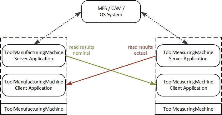
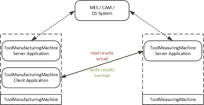
B.2.1 System architecture with server and client on both machines
This deployment option describes that a cutting tool client application is running on both machines as well as in the higher-level IT system. The higher-level system client application uses the job management to facilitate the job management use case described in OPC 40001-3. Additionally, it puts the geometric data exchange file using the CuttingToolFileType as a work master on the tool manufacturing machine which is referenced in the job management. The tool measuring machine uses a separate client application to monitor the tool manufacturing machine job progress, reacting to the job completion and uses the work master file as an input for the measurement job commanded by the higher-level IT system. The tool manufacturing machine monitors the measuring machine again with a separate client application waiting for the nominal results of the measurement to facilitate the closed loop cutting tool manufacturing process.
The system architecture is shown schematically in Figure 8.
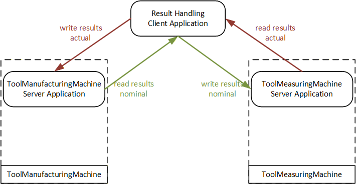
B.2.2 System architecture with server on both machines and an external client
This deployment option describes that a cutting tool client application is running only in an external IT system. The higher-level system client application uses the job management to facilitate the job management use case described in OPC 40001-3. It stores and retrieves the files representing the work masters to the tool manufacturing machine and measuring machine using the CuttingToolFileType as a work master. Therefore, it is necessary to listen to state changes of the 6:ISA95JobResponseProviderObjectType of either machine to synchronize the jobs being carried out.
The system architecture is shown schematically in Figure 9.
B.2.3 System architecture with server on both machines and client on one machine
This deployment option describes that a cutting tool client application synchronising manufacturing and measuring operations is running only on the tool manufacturing machine. The higher-level system client application uses the job management to facilitate the job management use case described in OPC 40001-3. It stores and retrieves the files representing the work masters to the tool manufacturing machine and measuring machine using the CuttingToolFileType as a work master. Furthermore, the client application running on the tool manufacturing machine facilitates the exchange of work master files between the tool manufacturing machine and measuring machine synchronizing the jobs being carried out. Alternatively, the synchronising client application could also run on the measuring machine.
The system architecture is shown schematically in Figure 10.
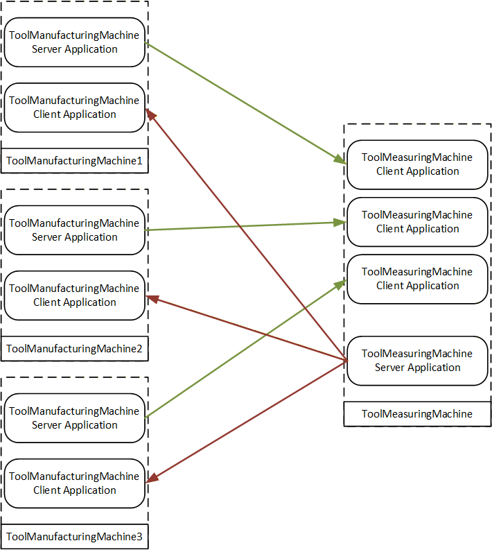
B.2.4 System architecture for connection of multiple machines
This deployment option shows the system architecture B.2.1 for the connection of multiple tool manufacturing machines with one measuring machine.
The system architecture is shown schematically in Figure 11.
___________
Agreement of Use
COPYRIGHT RESTRICTIONS
This document is provided "as is" by the OPC Foundation and VDMA.
Right of use for this specification is restricted to this specification and does not grant rights of use for referred documents.
Right of use for this specification will be granted without cost.
This document may be distributed through computer systems, printed or copied as long as the content remains unchanged and the document is not modified.
OPC Foundation and VDMA do not guarantee usability for any purpose and shall not be made liable for any case using the content of this document.
The user of the document agrees to indemnify OPC Foundation and VDMA and their officers, directors and agents harmless from all demands, claims, actions, losses, damages (including damages from personal injuries), costs and expenses (including attorneys' fees) which are in any way related to activities associated with its use of content from this specification.
The document shall not be used in conjunction with company advertising, shall not be sold or licensed to any party.
The intellectual property and copyright is solely owned by the OPC Foundation and VDMA.
PATENTS
The attention of adopters is directed to the possibility that compliance with or adoption of OPC or VDMA specifications may require use of an invention covered by patent rights. OPC Foundation or VDMA shall not be responsible for identifying patents for which a license may be required by any OPC or VDMA specification, or for conducting legal inquiries into the legal validity or scope of those patents that are brought to its attention. OPC or VDMA specifications are prospective and advisory only. Prospective users are responsible for protecting themselves against liability for infringement of patents.
WARRANTY AND LIABILITY DISCLAIMERS
WHILE THIS PUBLICATION IS BELIEVED TO BE ACCURATE, IT IS PROVIDED "AS IS" AND MAY CONTAIN ERRORS OR MISPRINTS. THE OPC FOUDATION NOR VDMA MAKES NO WARRANTY OF ANY KIND, EXPRESSED OR IMPLIED, WITH REGARD TO THIS PUBLICATION, INCLUDING BUT NOT LIMITED TO ANY WARRANTY OF TITLE OR OWNERSHIP, IMPLIED WARRANTY OF MERCHANTABILITY OR WARRANTY OF FITNESS FOR A PARTICULAR PURPOSE OR USE. IN NO EVENT SHALL THE OPC FOUNDATION NOR VDMA BE LIABLE FOR ERRORS CONTAINED HEREIN OR FOR DIRECT, INDIRECT, INCIDENTAL, SPECIAL, CONSEQUENTIAL, RELIANCE OR COVER DAMAGES, INCLUDING LOSS OF PROFITS, REVENUE, DATA OR USE, INCURRED BY ANY USER OR ANY THIRD PARTY IN CONNECTION WITH THE FURNISHING, PERFORMANCE, OR USE OF THIS MATERIAL, EVEN IF ADVISED OF THE POSSIBILITY OF SUCH DAMAGES.
The entire risk as to the quality and performance of software developed using this specification is borne by you.
RESTRICTED RIGHTS LEGEND
This Specification is provided with Restricted Rights. Use, duplication or disclosure by the U.S. government is subject to restrictions as set forth in (a) this Agreement pursuant to DFARs 227.7202-3(a); (b) subparagraph (c)(1)(i) of the Rights in Technical Data and Computer Software clause at DFARs 252.227-7013; or (c) the Commercial Computer Software Restricted Rights clause at FAR 52.227-19 subdivision (c)(1) and (2), as applicable. Contractor / manufacturer are the OPC Foundation, 16101 N. 82nd Street, Suite 3B, Scottsdale, AZ, 85260-1830.
COMPLIANCE
The combination of VDMA and OPC Foundation shall at all times be the sole entities that may authorize developers, suppliers and sellers of hardware and software to use certification marks, trademarks or other special designations to indicate compliance with these materials as specified within this document. Products developed using this specification may claim compliance or conformance with this specification if and only if the software satisfactorily meets the certification requirements set by VDMA or the OPC Foundation. Products that do not meet these requirements may claim only that the product was based on this specification and must not claim compliance or conformance with this specification.
TRADEMARKS
Most computer and software brand names have trademarks or registered trademarks. The individual trademarks have not been listed here.
GENERAL PROVISIONS
Should any provision of this Agreement be held to be void, invalid, unenforceable or illegal by a court, the validity and enforceability of the other provisions shall not be affected thereby.
This Agreement shall be governed by and construed under the laws of Germany.
This Agreement embodies the entire understanding between the parties with respect to, and supersedes any prior understanding or agreement (oral or written) relating to, this specification.