
1 Scope
OPC 40082-4 describes the data model for dosing systems as part of a plastic & rubber production cell/line (e.g. extrusion/injection moulding) for data exchange with manufacturing execution systems (MES) and other components of the cell/line. Dosed materials may be granulate, powder or liquids. For liquid silicon and rubber dosing systems, please refer to OPC 40082-3: LSR Dosing Systems. This specification is applicable for dosing systems mounted directly on the machine as well as for systems not directly mounted on the machine (e.g. floor-mounted).
The target of OPC 40082-4 is to provide a unique interface for dosing systems from different manufacturers to ensure compatibility.
The following functionalities are covered:
General information about the dosing system (manufacturer, model, serial number…), current configuration and status.
Process information like throughput for monitoring and process optimization.
Closed loop controls between the components of the production cell/line.
Following functions are not included:
Safety related signals like emergency stop
2 Normative references
The following documents are referred to in the text in such a way that some or all of their content constitutes requirements of this document. For dated references, only the edition cited applies. For undated references, the latest edition of the referenced document (including any amendments and errata) applies
OPC 10000-1, OPC Unified Architecture - Part 1: Overview and Concepts
OPC 10000-1
OPC 10000-3, OPC Unified Architecture - Part 3: Address Space Model
OPC 10000-3
OPC 10000-5, OPC Unified Architecture - Part 5: Information Model
OPC 10000-5
OPC 10000-6, OPC Unified Architecture - Part 6: Mappings
OPC 10000-6
OPC 10000-7, OPC Unified Architecture - Part 7: Profiles
OPC 10000-7
OPC 10000-8, OPC Unified Architecture - Part 8: Data Access
OPC 10000-8
OPC 10000-9, OPC Unified Architecture - Part 9: Alarms and Conditions
OPC 10000-9
OPC 10000-100, OPC Unified Architecture - Part 100: Devices
OPC 10000-100
OPC 40001-1, OPC UA for Machinery - Part 1: Basic Building Blocks
http://www.opcfoundation.org/UA/Machinery/
OPC 40083: OPC UA interfaces for plastics and rubber machinery - General Type definitions
http://www.opcfoundation.org/UA/PlasticsRubber/GeneralTypes
3 Terms, definitions and conventions
3.1 Overview
It is assumed that basic concepts of OPC UA information modelling are understood in this specification. This specification will use these concepts to describe the OPC 40082-4 Information Model. For the purposes of this document, the terms and definitions given in the documents referenced in Clause 2 apply.
3.2 Conventions used in this document
The conventions described in OPC 40083 apply.
3.3 Abbreviations
| EXT | Extruder |
| IMM | Injection Moulding Machine |
| MES | Manufacturing Execution System |
4 General information to OPC UA interfaces for plastics and rubber machinery and OPC UA
For general information on OPC UA interfaces for plastics and rubber machinery and OPC UA see OPC 40083.
For liquid silicon and rubber dosing systems, please refer to OPC 40082-3: LSR Dosing Systems.
5 Use cases
The following functionalities are covered:
General information about the dosing system (manufacturer, model, serial number… ), current configuration and status.
Optimizing process: Throughput of dosing has to be adjusted with other components in the production cell/line (e.g. extruder/haul-off speed).
Process information (throughput, actual weight)
Monitoring (Status, Errors)
Recipe management: Dosing systems store their configurations in so-called recipes. These include information on nominal process parameters (temperatures, dosing volumes …). OPC 40082-4 allows transferring datasets between dosing systems and MES/line controllers for building a central repository of recipes.
6 OPC 40082-4 Information Model overview
The task of a dosing system is to bring material into the production process. This can be done in a continuous or discontinuous manner (batch) or a combination of both (see Figure 1 for an example). The material can be gravity fed or controlled and combined with an optional starve feeder (e.g. for extrusion).
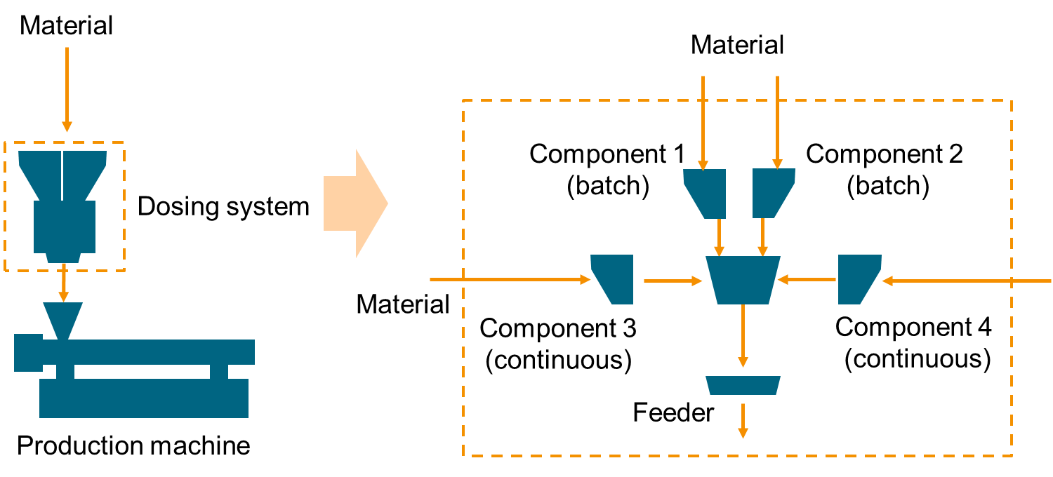
The information model defined in this specification models the complex structure of a dosing system as follows:
The top level ObjectType DosingSystemType contains the objects for machine identification, machine state and configuration of the complete dosing system. The individual components are modelled in the OperationType with all properties required to monitor and control the operation of the system.
7 DosingSystemType
7.1 DosingSystemType definition
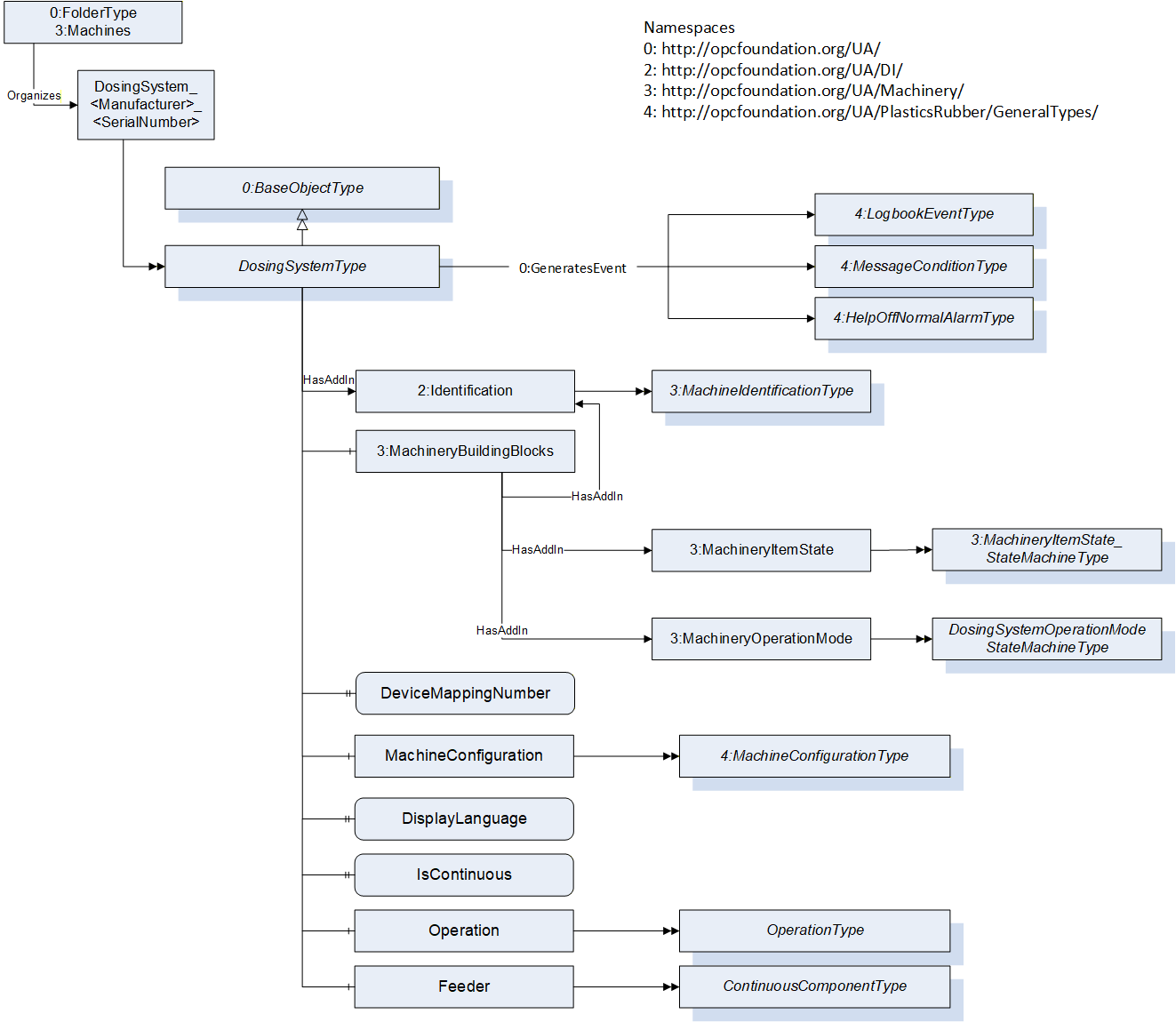
This OPC UA ObjectType is used for the root Object representing a dosing system as part of a production cell/line. It is formally defined in Table 1.
The instance(s) of DosingSystemType shall be located under the Machines Object of the Server (see OPC UA for Machinery).
| Attribute | Value | ||||
| BrowseName | DosingSystemType | ||||
| IsAbstract | False | ||||
| References | Node Class | BrowseName | DataType | TypeDefinition | Other |
|---|---|---|---|---|---|
| Subtype of the 0:BaseObjectType defined in OPC 10000-5 | |||||
| 0:HasAddIn | Object | 2:Identification | 3:MachineIdentification Type | M | |
| 0:HasComponent | Object | 3:MachineryBuildingBlocks | 0:FolderType | M | |
| 0:HasComponent | Object | MachineConfiguration | 4:MachineConfigurationType | M | |
| 0:HasProperty | Variable | DisplayLanguage | 0:LocaleId | 0:PropertyType | O, RW |
| 0:HasProperty | Variable | IsContinuous | 0:Boolean | 0:PropertyType | M, RO |
| 0:HasComponent | Object | Operation | OperationType | M | |
| 0:HasProperty | Variable | DeviceMappingNumber | 0:UInt32 | 0:PropertyType | M, RW |
| 0:HasComponent | Object | Feeder | ContinuousComponentType | O | |
| 0:GeneratesEvent | ObjectType | 4:LogbookEventType | Defined in OPC 40083 | ||
| 0:GeneratesEvent | ObjectType | 4:MessageConditionType | Defined in OPC 40083 | ||
| 0:GeneratesEvent | ObjectType | 4:HelpOffNormalAlarmType | Defined in OPC 40083 | ||
| Conformance Units | |||||
|---|---|---|---|---|---|
| OPC 40082-4 Basic | |||||
| OPC 40082-4 Alarms |
7.2 Identification and MachineryBuildingBlocks
The MachineIdentificationType is defined in OPC UA for Machinery (OPC 40001-1) and provides basic information on a machine/device.
For the InstanceDeclaration the ModellingRules of the Properties Model and DeviceClass are overridden to mandatory.
The Object MachineryBuildingBlocks contains building blocks from OPC UA for Machinery as defined in OPC 40001-1. For this version of OPC 40082-4, the Object uses the two AddIns MachineryItemState and MachineryOperationMode.
| BrowsePath | References | NodeClass | BrowseName | DataType | TypeDefinition | Other |
| 2:Identification | 0:HasProperty | Variable | 2:Model | 0:LocalizedText | 0:PropertyType | M, RO |
| 2:Identification | 0:HasProperty | Variable | 2:DeviceClass | 0:String | 0:PropertyType | M, RO |
| 3:MachineryBuildingBlocks | 0:HasAddIn | Object | 3:MachineryItemState | 3:MachineryItemState_StateMachineType | M | |
| 3:MachineryBuildingBlocks | 0:HasAddIn | Object | 3:MachineryOperationMode | 3:MachineryOperationModeStateMachineType | M |
The DeviceClass Property shall have the value "Dosing System".
The components of the DosingSystemType have additional references which are defined in Table 3.
| SourceBrowsePath | Reference Type | Is Forward | TargetBrowsePath |
| 3:MachineryBuildingBlocks | 0:HasAddIn | True | 2:Identification |
7.2.1 Machine State and Operation Mode
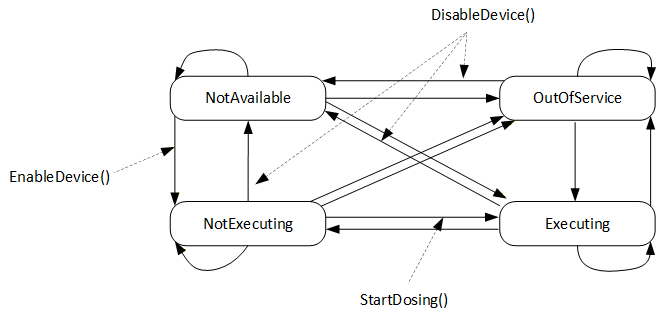
To provide the machine state, this specification uses the AddIn MachineryItemState from OPC 40001-1. Different Methods defined in this specification non-exclusively trigger state transitions, meaning that the server can also trigger these transitions in other ways (e.g. HMI input, control logic…):
EnableDevice (defined in 8.5) triggers the transition from NotAvailable to NotExecuting by e.g. switching on the drives of the device. NotExecuting means, the dosing device is ready for dosing and waiting for a dosing signal.
DisableDevice (defined in 8.6) triggers the transition from any state to NotAvailable by e.g. switching off the drives of the device. Further SubStates like e.g. "sleep", "energy saving", "eco mode" or "off" are not defined in this specification.
StartDosing (defined in 8.7) triggers the transition from NotExecuting to Executing if RemoteControlActivated (defined in ) is in mode "OPC UA" (2). If not, the transition is performed by the server.
The transition from Executing state to any other state can be triggered in different ways depending on the application, e.g. automatically by the server in IMM application after each cycle or by the methods StopDosing or StopDosingAfterCycle in case of continuous dosing.
Figure 3 gives an overview of the machine state, transitions and methods.
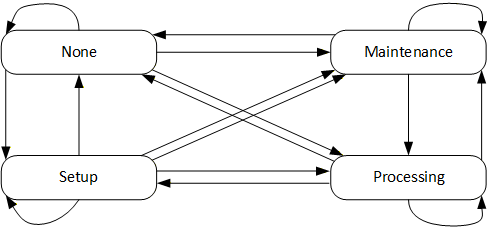
For the operation modes, the MachineryOperationMode state machine is used without changes:
7.3 DeviceMappingNumber
| Description: | Unique identifier/address/number for devices of the same DeviceType within a local network. Several peripheral devices of the same DeviceType can be connected to a production machine (e.g. IMM or extruder). In most applications, the production machine must map the connected peripheral devices to internal logical devices and zones in a fixed configuration (e.g. hot runner systems according to the wiring or temperature control devices according to the tubing). |
The mapping shall be stable after reconnecting the devices and is therefore not possible via IP addresses, which can be assigned dynamically via DHCP. DeviceMappingNumber sets the mapping order of peripheral devices of the same type on the local network and is therefore of type UInt32.
| Example: | 1 |
7.4 MachineConfiguration
The MachineConfiguration Object represents the current configuration of the Dosing System. The MachineConfigurationType is defined in OPC 40083.
7.5 DisplayLanguage
With the DisplayLanguage Property the client can set the desired language on the user interface at the Dosing System. If the peripheral device does not support the configured language, it can keep the previous setting or use English as the default.
7.6 IsContinuous
The dosing device can be installed on an extruder (EXT) or an injection moulding machine (IMM). EXT is a continuous process, IMM is a cyclic process. For inline dosing devices, directly mounted on the feed throat of an IMM the IsContinuous flag is false, when installed on an EXT this flag is true.
For batch blenders which are cyclic based by themselves, this flag is set true since the output flow of a batch blender does not need to be synchronized with for example an IMM.
7.7 Operation
This ObjectType contains parameters which are necessary to operate the Dosing System. The OperationType is defined in chapter 8.
7.8 Feeder
A feeder can be used for starve feeding (under feeding) of a production machine and is defined by the ContinuousComponentType. E.g. a screw feeder where DosingMode is set to ONLY_CONVEYING. The ContinuousComponentType is defined in chapter11.20.
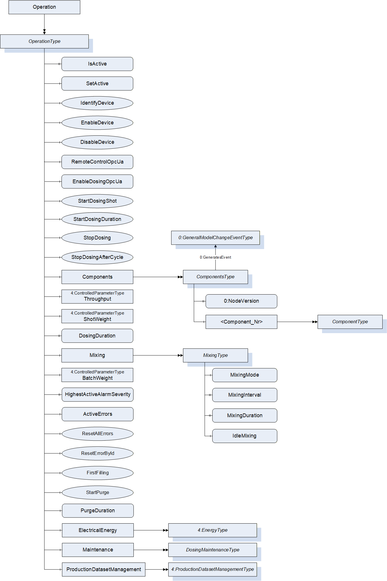
8 OperationType
8.1 OperationType definition
The OperationType contains objects which are necessary to operate the DosingSystem. It is formally defined in Table 4. The top level of the OperationType describes the whole dosing system while detailed information about the single components can be found in the ComponentsType Object.
| Attribute | Value | ||||
| BrowseName | OperationType | ||||
| IsAbstract | False | ||||
| References | Node Class | BrowseName | DataType | TypeDefinition | Other |
|---|---|---|---|---|---|
| Subtype of 0:BaseObjectType defined in OPC 10000-5 | |||||
| 0:HasProperty | Variable | IsActive | 0:Boolean | 0:PropertyType | O, RO |
| 0:HasComponent | Variable | SetActive | 0:Boolean | 0:BaseDataVariableType | O, RW |
| 0:HasComponent | Method | IdentifyDevice | O | ||
| 0:HasComponent | Method | EnableDevice | M | ||
| 0:HasComponent | Method | DisableDevice | M | ||
| 0:HasComponent | Variable | RemoteControlOpcUa | 0:Boolean | 0:BaseDataVariableType | M |
| 0:HasComponent | Variable | EnableDosingOpcUa | 0:Boolean | 0:BaseDataVariableType | M |
| 0:HasComponent | Method | StartDosingShot | O | ||
| 0:HasComponent | Method | StartDosingContinuous | O | ||
| 0:HasComponent | Method | StopDosing | O | ||
| 0:HasComponent | Method | StopDosingAfterCycle | O | ||
| 0:HasComponent | Object | Components | ComponentsType | M | |
| 0:HasComponent | Object | Throughput | 4:ControlledParameterType | O | |
| 0:HasComponent | Object | ShotWeight | 4:ControlledParameterType | O | |
| 0:HasComponent | Variable | DosingDuration | 0:Duration | 0:BaseDataVariableType | O, RW |
| 0:HasComponent | Object | Mixing | MixingType | O | |
| 0:HasComponent | Object | BatchWeight | 4:ControlledParameterType | O | |
| 0:HasProperty | Variable | HighestActiveAlarmSeverity | 0:UInt16 | 0:PropertyType | M, RO |
| 0:HasComponent | Variable | ActiveErrors | 4:ActiveErrorDataType[] | 0:BaseDataVariableType | M, RO |
| 0:HasComponent | Method | ResetAllErrors | O | ||
| 0:HasComponent | Method | ResetErrorById | O | ||
| 0:HasComponent | Method | FirstFilling | O | ||
| 0:HasComponent | Method | StartPurge | O | ||
| 0:HasComponent | Variable | PurgeDuration | 0:Duration | 0:BaseDataVariableType | O |
| 0:HasComponent | Object | ElectricalEnergy | 4:EnergyType | O | |
| 0:HasComponent | Object | Maintenance | DosingMaintenanceType | O | |
| 0:HasComponent | Object | ProductionDataSetManagement | 4:ProductionDatasetManagementType | O | |
| Conformance Units | |||||
|---|---|---|---|---|---|
| OPC 40082-4 Basic |
8.2 IsActive
The IsActive Property provides information if the dosing unit is active in the current production.
8.3 SetActive
The SetActive variable activates the dosing unit for the current production.
NOTE: Malfunction or activation by mistake should be covered on machine side (not part of this specification).
8.4 IdentifyDevice
The DosingSystem on which this method is called shows itself by e.g. activation of a LED.
Signature: IdentifyDevice();| Attribute | Value | ||||
| BrowseName | IdentifyDevice | ||||
| References | Node Class | BrowseName | DataType | TypeDefinition | Modelling Rule |
|---|
NOTE: This Method is identical to the IdentifyDevice Method in OPC 40082-1.
8.5 EnableDevice
Enables the device, for example activate motor drives. Triggers the transition from MachineryItemState NotAvailable to NotExecuting.
Signature: EnableDevice();| Attribute | Value | ||||
| BrowseName | EnableDevice | ||||
| References | Node Class | BrowseName | DataType | TypeDefinition | Modelling Rule |
|---|
8.6 DisableDevice
Disables the device, for example deactivate motor drives. Triggers the transition from any MachineryItemState to NotAvailable.
Signature: DisableDevice();| Attribute | Value | ||||
| BrowseName | DisableDevice | ||||
| References | Node Class | BrowseName | DataType | TypeDefinition | Modelling Rule |
|---|
8.7 RemoteControlOpcUa
Variable to set and read the actual remote control state of the server instance. If RemoteControlOpcUa is FALSE, the interface is read-only (Variables not writeable, methods not executable).
RemoteControlOpcUa remains writeable, even if set to FALSE.
8.8 EnableDosingOpcUa
Variable to set and read the actual state how the dosing signal is transferred from the client to the dosing system in addition to RemoteControlOpcUa.
If EnableDosingOpcUa is FALSE, dosing has to be triggered by another interface, e.g. hard-wired signals.
If RemoteControlOpcUa is FALSE, EnableDosingOpcUa shall be ignored.
8.9 StartDosingShot
If EnableDosingOpcUa is TRUE, this method can be used to start dosing for one shot with a defined duration specified by DosingDuration, no arguments.
If EnableDosingOpcUa is FALSE, the return statement shall be "Bad_InvalidState"
In case of inline dosing in a cyclic production process, this method needs to be called every cycle.
Signature
StartDosingShot();| Attribute | Value | ||||
| BrowseName | StartDosingShot | ||||
| References | Node Class | BrowseName | DataType | TypeDefinition | Modelling Rule |
|---|
If StartDosingShot is used, DosingDuration becomes mandatory.
8.10 StartDosingContinuous
If EnableDosingOpcUa is TRUE, this method can be used to start dosing continuously, no arguments.
If EnableDosingOpcUa is FALSE, the return statement shall be "Bad_InvalidState"
Signature
StartDosingContinuous();| Attribute | Value | ||||
| BrowseName | StartDosingContinuous | ||||
| References | Node Class | BrowseName | DataType | TypeDefinition | Modelling Rule |
|---|
8.11 StopDosing
Method to stop dosing immediately. No arguments.
Signature
StopDosing();| Attribute | Value | ||||
| BrowseName | StopDosing | ||||
| References | Node Class | BrowseName | DataType | TypeDefinition | Modelling Rule |
|---|
8.12 StopDosingAfterCycle
Method to stop dosing after the current dosing cycle (e.g. to get a valid batch mix with batch blending). No arguments.
Signature
StopDosingAfterCycle();| Attribute | Value | ||||
| BrowseName | StopDosingAfterCycle | ||||
| References | Node Class | BrowseName | DataType | TypeDefinition | Modelling Rule |
|---|
8.13 Components
This ObjectType is a container for all Components in the DosingSystem. The ComponentsType is described in chapter 11.
8.14 Throughput
Current throughput of the DosingSystem in mass or volume per time. The modelling rule for this node is optional to cover pure feeders, but is mandatory for all other dosing units.
Unit: kg/h or lb/h
8.15 ShotWeight
Current shotweight of the parts produced by the production machine in mass.
Unit: g or oz
8.16 DosingDuration
Used for inline dosing where the dosing device is mounted on the feed throat of the production machine. This parameter defines the duration the dosing shall be active after receiving the StartDosingShot signal.
If DosingDuration is used, the dosing device shall stop dosing after the duration. StopDosing or StopDosingAfterCycle are not necessary in this case but shall have a higher priority if used anyway.
8.17 Mixing
In case the dosing station is equipped with an active mixing device like a batch blender, this object provides information about the mixing process. The MixingType is defined in chapter 9.
8.18 BatchWeight
Target batch weight for batch blenders in absolute values.
Unit: g or oz
8.19 HighestActiveAlarmSeverity
| Description: | Indication of the severity of the highest active alarm (0 = no active alarm - 1000 = possible error). Together with ActiveErrors, it provides a minimal error handling for devices without alarm support. However, the variable shall be filled even if alarms are supported. |
| The severity classification defined in OPC 40083 (clause 6.4) shall be used. | |
| Example: | 400 |
8.20 ActiveErrors
| Description: | List of the active errors of the device. It provides a minimal error handling for devices without alarm support. However, the variable shall be filled even if alarms are supported. The ActiveErrorDataType is defined in OPC 40083. If there is no active error, the array is empty. |
8.21 ResetAllErrors
| Description: | Method to reset all errors of the device. |
Signature
ResetAllErrors();8.22 ResetErrorById
| Description: | Method to reset one error of the device. |
Signature
	ResetErrorById(
[in] String Id);| Argument | Description |
| Id | Id of the error, listed in ActiveErrors, that shall be reset. |
| Attribute | Value | ||||
| BrowseName | ResetErrorById | ||||
| References | Node Class | BrowseName | DataType | TypeDefinition | Modelling Rule |
|---|---|---|---|---|---|
| HasProperty | Variable | InputArguments | Argument[] | PropertyType | Mandatory |
8.23 FirstFilling
Method to fill the DosingSystem for the first time with the mixture of materials from the current recipe.
No Arguments.
Signature: FirstFilling();
| Attribute | Value | ||||
| BrowseName | FirstFilling | ||||
| References | Node Class | BrowseName | DataType | TypeDefinition | Modelling Rule |
|---|
8.24 StartPurge
Method to start the purging function on the dosing system. No arguments.
Once purging, the State of all components will be set to "Purging" and can be used to monitor if the purging sequence has finished.
Signature
StartPurge();| Attribute | Value | ||||
| BrowseName | StartPurge | ||||
| References | Node Class | BrowseName | DataType | TypeDefinition | Modelling Rule |
|---|
8.25 PurgeDuration
Duration of the purging function of the dosing system.
8.26 ElectricalEnergy
Information about the electrical power and energy consumption of the DosingSystem. The EnergyType is defined in OPC 40083.
8.27 Maintenance
Information on the maintenance status of the dosing system. The DosingMaintenanceType is defined in chapter 16.
8.28 ProductionDatasetManagement
The ProductionDatasetManagementType is defined in OPC 40083 and provides functionalities for the management of recipes/machine settings.
9 MixingType
9.1 MixingType definition
In case the dosing station is equipped with an active mixing device like on a batch blender, the mixing process can be controlled with the type MixingType, which is defined in Table 16.
| Attribute | Value | ||||
| BrowseName | MixingType | ||||
| IsAbstract | False | ||||
| References | Node Class | BrowseName | DataType | TypeDefinition | Other |
|---|---|---|---|---|---|
| Subtype of 0:BaseObjectType defined in OPC UA Part 5 | |||||
| 0:HasComponent | Variable | MixingMode | 0:UInt16 | 0:MultiStateValueDiscreteType | M, RW |
| 0:HasProperty | Variable | MixingInterval | 0:UInt16 | 0:PropertyType | O, RW |
| 0:HasProperty | Variable | MixingDuration | 0:Duration | 0:PropertyType | O, RW |
| 0:HasComponent | Variable | IdleMixing | 0:Boolean | 0:BaseDataVariableType | O, RW |
9.2 MixingMode
The mixing mode parameter can be used to set the required mixing mode. The MultiStateValueDiscreteType should provide the available mixing modes.
| EnumValue | ValueAsText | Description |
| 0 | NO_MIXING | No mixer available or mixing OFF |
| 1 | CONTINUOUS_MIXING | Mixer is activated after the first batch (blender) and is mixing continuous until the dosing device is stopped |
| 2 | TIMED_MIXING | The mixer is started after each batch (blender) and mixes for a defined duration (MixingDuration 9.4) |
| 3 | INTERVAL_MIXING | The mixer device is started after a defined number of shots, IMM (MixingInterval 9.3). Duration of mixing is set by MixingDuration |
9.3 MixingInterval
Interval between two mixing processes, in number of shots
Note: Mandatory if MixingMode is set to INTERVAL_MIXING
9.4 MixingDuration
Duration of a mixing process
Note: Mandatory, if MixingMode is set to TIMED_MIXING or INTERVAL_MIXING
9.5 IdleMixing
This flag can be used for "idle mixing". With idle mixing the mixer of the batch blender rotates once in a while to keep the material in the mixer flowing and material does not get blocked by the mixer blades.
10 ComponentsType
10.1 ComponentsType definition
This ObjectType is a container for all Components in the DosingSystem. It is formally defined in Table 18.
| Attribute | Value | ||||
| BrowseName | ComponentsType | ||||
| IsAbstract | False | ||||
| References | Node Class | BrowseName | DataType | TypeDefinition | Other |
|---|---|---|---|---|---|
| Subtype of 0:BaseObjectType defined in OPC 10000-5 | |||||
| 0:HasProperty | Variable | 0:NodeVersion | 0:String | 0:PropertyType | M, RO |
| 0:HasComponent | Object | <Component_Nr> | ComponentType | MP | |
| 0:GeneratesEvent | ObjectType | 0:GeneralModelChangeEventType | Defined in OPC 10000-5 | ||
| Conformance Units |
| OPC 40082-4 Basic |
When instances for components are created, the BrowseNames shall be "<Component_Nr>" where Nr is a three-digit number with leading zeros, starting with "001". The ComponentType is defined in chapter 11.
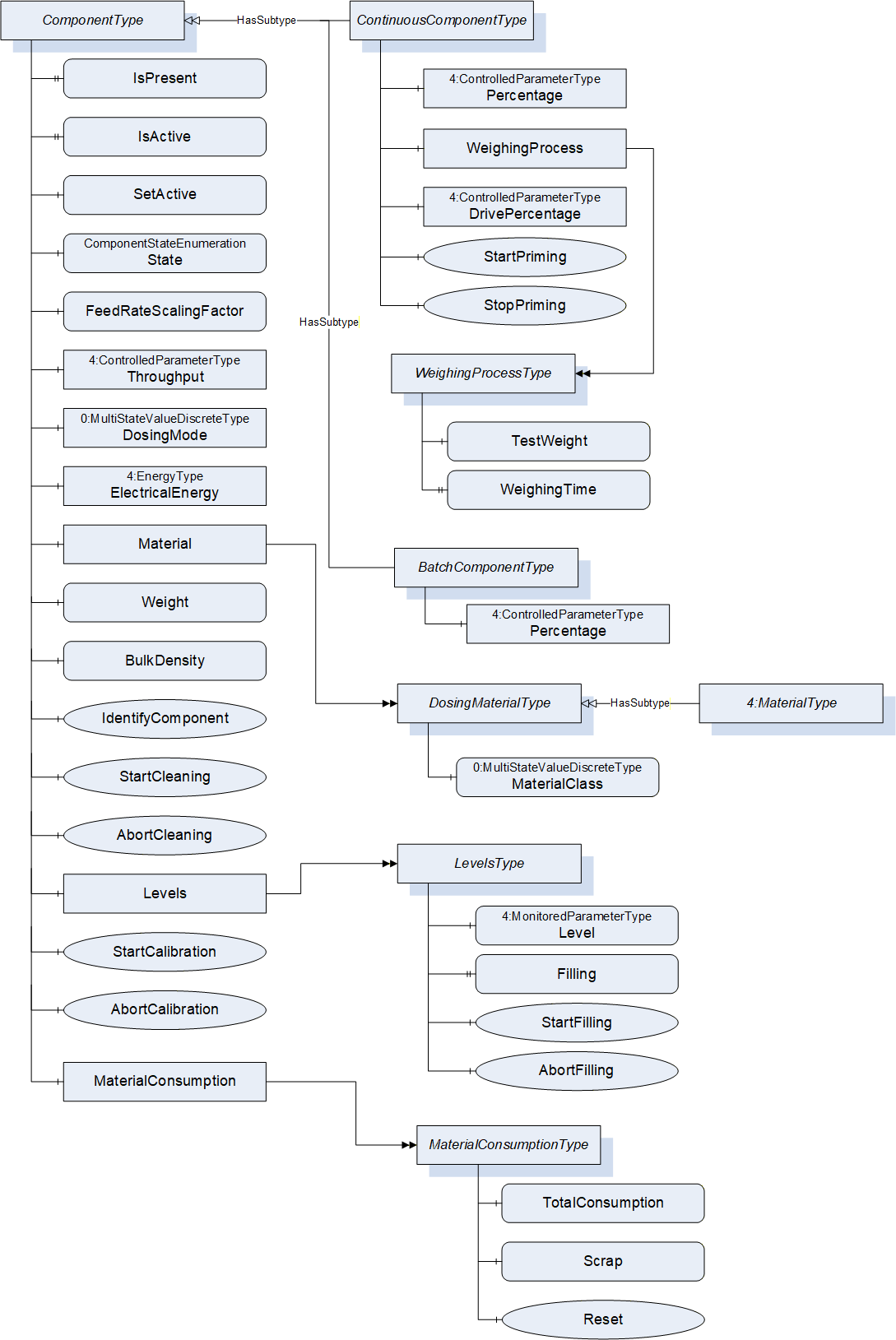
11 ComponentType
11.1 ComponentType definition
The ComponentType represents a device which brings material into the dosing system. For the component name, the Node Attribute DisplayName shall be used.
The ComponentType is abstract. A derived subtype, either for continuous dosing (ContinuousComponentType) or discontinuous dosing (BatchComponentType) shall be used.
Free falling components shall be modelled with DosingMode "Only_Conveying".
| Attribute | Value | ||||
| BrowseName | ComponentType | ||||
| IsAbstract | True | ||||
| References | Node Class | BrowseName | DataType | TypeDefinition | Other |
|---|---|---|---|---|---|
| Subtype of 0:BaseObjectType defined in OPC 10000-5 | |||||
| 0:HasProperty | Variable | IsPresent | 0:Boolean | 0:PropertyType | M, RO |
| 0:HasProperty | Variable | IsActive | 0:Boolean | 0:PropertyType | O, RO |
| 0:HasComponent | Variable | SetActive | 0:Boolean | 0:BaseDataVariableType | O, RW |
| 0:HasComponent | Variable | State | ComponentStateEnumeration | 0:BaseDataVariableType | M, RO |
| 0:HasProperty | Variable | FeedRateScalingFactor | 0:Double | 0:PropertyType | O, RW |
| 0:HasComponent | Object | Throughput | 4:ControlledParameterType | O | |
| 0:HasComponent | Variable | DosingMode | 0:UInt16 | 0:MultiStateValueDiscreteType | M, RW |
| 0:HasComponent | Object | ElectricalEnergy | 4:EnergyType | O | |
| 0:HasComponent | Object | Material | DosingMaterialType | O | |
| 0:HasComponent | Object | MaterialConsumption | MaterialConsumptionType | O | |
| 0:HasComponent | Variable | Weight | 0:Double | 0:AnalogUnitType | O, RO |
| 0:HasComponent | Variable | BulkDensity | 0:Double | 0:AnalogUnitType | O, RW |
| 0:HasComponent | Method | IdentifyComponent | O | ||
| 0:HasComponent | Method | StartCleaning | O | ||
| 0:HasComponent | Method | AbortCleaning | O | ||
| 0:HasComponent | Object | Levels | LevelsType | O | |
| 0:HasComponent | Method | StartCalibration | O | ||
| 0:HasComponent | Method | AbortCalibration | O | ||
| 0:HasSubtype | ObjectType | ContinuousComponentType | Defined in 11.20 | ||
| 0:HasSubtype | ObjectType | BatchComponentType | Defined in 11.21 | ||
| Conformance Units | |||||
|---|---|---|---|---|---|
| OPC 40082-4 Basic |
11.2 IsPresent
The IsPresent flag indicates if the hardware of this component is installed. This IsPresent system is used for those Dosing equipment manufacturers using a fixed OPC UA model for different hardware models
11.3 SetActive
The SetActive variable activates the dosing component for the current production. SetActive = False deactivates the component, even if the setpoint is bigger than 0 % in the recipe.
NOTE: In some cases where the dosing Percentage setpoint of this component is bigger than 0 % and SetActive = False, the real total material output of the dosing station is not 100 % but 100 %-x % of this component.
Example: a dosing station with 3 components, respectively 80%, 15%, 5% and an Extruder Throughput demand of 100 kg/h. The component of 5 % SetActive = False. The dosing system will actually supply 95 % (95 kg/h).
11.4 IsActive
The IsActive Property provides information if the dosing component is active in the current production.
11.5 State
The State property of this component to read the actual working state of the component.
| Name | Value | Description |
| Off | 0 | The component has been switched off |
| Ready | 1 | The component is waiting for a start dosing signal |
| Dosing | 2 | The component is actively feeding material |
| Calibration | 3 | Component is in calibration mode and can typically not be used for dosing or filling |
| Error | 4 | The component has an active error |
| Cleaning | 5 | The component is in cleaning mode e.g. hopper draining |
| Purging | 6 | The component is in purging mode |
| Priming | 7 | The component is in priming mode |
11.6 FeedrateScalingFactor
Material-specific output of the Component per DrivePercentage.
Example:
A dosing screw with a maximum rotational speed of 300 rpm, the material output flow is 900 grams per second. 300 rpm means 100 % DrivePercentage. The Feedrate would then be 900/100 = 9 gram per % per second (g/(%*s))
Running at 50 % DrivePercentage, the output will be 50*9 = 450 g/s.
Example:
A vibrational feeder running at 50 Hz, the material output flow is 10 gram per second. The maximum frequency of the feeder is 250 Hz. 250 Hz equals 100 % DrivePercentage, 50 Hz equals 20 % DrivePercentage. The feederate is 10/20 = 0.5 gram per % per second (g/%/s).
11.7 Throughput
Material Output per time.
Unit: kg/h or lb/h
11.8 DosingMode
The DosingMode Property provides information, how the dosing of the component is controlled.
| Name | Value | Description |
| ONLY_CONVEYING | 0 | The throughput is not controlled. The feeder only transports the material (e.g. by screw, conveyor belt) or the material is only falling through a feed opening. |
| VOLUMETRIC | 1 | The throughput is controlled by a volumetric dosing system. |
| GRAVIMETRIC | 2 | The throughput is controlled by a gravimetric dosing system. |
| OTHER | 3 | Throughput is controlled, but in another mode than these above. |
11.9 ElectricalEnergy
Information about the electrical power and energy consumption of the component. The EnergyType is defined in OPC 40083.
11.10 Material
Information about the material used in the component. The MaterialType is defined in OPC 40083.
11.11 Weight
Weight of the Material (e.g. inside the hopper).
Unit: g or oz
11.12 BulkDensity
Bulk density of the material which is dosed (not to be confused with the density of the material itself defined in MaterialType).
Unit: kg/l or lb/gal or lb/ft³
11.13 IdentifyComponent
The dosing component on which this method is called shows itself by e.g. activation of a LED.
Signature: IdentifyComponent();NOTE: This Method is identical to the IdentifyDevice Method in OPC 40082-1.
| Attribute | Value | ||||
| BrowseName | IdentifyComponent | ||||
| References | Node Class | BrowseName | DataType | TypeDefinition | Modelling Rule |
|---|
11.14 StartCleaning
Start the automated cleaning sequence for this component. Once cleaning the component State will be set to Cleaning and can be used to monitor if cleaning sequence has finished.
Method without arguments.
Signature: StartCleaning();
| Attribute | Value | ||||
| BrowseName | StartCleaning | ||||
| References | Node Class | BrowseName | DataType | TypeDefinition | Modelling Rule |
|---|
11.15 AbortCleaning
Method without arguments to abort the current cleaning sequence. If the device MachineryItemState is NotAvailable, the component State shall switch to Off, otherwise to Ready.
Signature: AbortCleaning();
| Attribute | Value | ||||
| BrowseName | AbortCleaning | ||||
| References | Node Class | BrowseName | DataType | TypeDefinition | Modelling Rule |
|---|
11.16 Levels
Information about the filling of the dosing component. The LevelsType is defined in chapter 12.
11.17 MaterialConsumption
Information about the material consumption of the component. The MaterialConsumptionType is defined in chapter 13.
11.18 StartCalibration
Start the automated calibration sequence for this component. Once calibrating the State will be set to "Calibration" and can be used to monitor if the calibration sequence has finished.
Material and BulkDensity should be supported.
Method without arguments.
Signature: StartCalibration();
| Attribute | Value | ||||
| BrowseName | StartCalibration | ||||
| References | Node Class | BrowseName | DataType | TypeDefinition | Modelling Rule |
|---|
11.19 AbortCalibration
Abort the current calibration sequence for this component.
Method without arguments.
Signature: AbortCalibration();
| Attribute | Value | ||||
| BrowseName | StartCalibration | ||||
| References | Node Class | BrowseName | DataType | TypeDefinition | Modelling Rule |
|---|
11.20 ContinuousComponentType
11.20.1 ContinuousComponentType definition
The ContinuousComponentType is a subtype of the abstract ComponentType and describes Components, where the materials are fed to the production machine in a continuous flow instead of batches. Injection moulding can be considered as continuous flow during plastification.
The ContinuousComponentType is formally defined in 11.20.
The dosing can be controlled with either (and only one of) Percentage or DrivePercentage.
| Attribute | Value | ||||
| BrowseName | ContinuousComponentType | ||||
| IsAbstract | False | ||||
| References | Node Class | BrowseName | DataType | TypeDefinition | Other |
|---|---|---|---|---|---|
| Subtype of ComponentType defined in 11 | |||||
| 0:HasComponent | Object | Percentage | 4:ControlledParameterType | O | |
| 0:HasComponent | Object | WeighingProcess | WeighingProcessType | O | |
| 0:HasComponent | Object | DrivePercentage | 4:ControlledParameterType | O | |
| 0:HasComponent | Method | StartPriming | O | ||
| 0:HasComponent | Method | StopPriming | O | ||
11.20.2 Percentage
Part (%) of the recipe dosed by this component (recipe).
11.20.3 WeighingProcess
The weighing process can be used to perform a material pre-calibration or to determine the feedrate of the dosing system used by this component.
The WeighingProcessType is defined in chapter 15.
11.20.4 DrivePercentage
Relative value (0-100%) of the maximum drive power of the component drive.
Example:
A dosing screw with a maximum rotational speed of 300 rpm. 300 rpm equals 100% DrivePercentage. At 50% DrivePercentage the screw rotates 150 rpm.
11.20.5 StartPriming
Method to start the priming function on the component. No arguments.
Once priming, the component State will be set to "Priming" and can be used to monitor if priming is active.
Signature: StartPriming();
| Attribute | Value | ||||
| BrowseName | StartPriming | ||||
| References | Node Class | BrowseName | DataType | TypeDefinition | Modelling Rule |
|---|
11.20.6 StopPriming
Method to stop the priming function on the component. No arguments.
Signature: StopPriming();
| Attribute | Value | ||||
| BrowseName | StopPriming | ||||
| References | Node Class | BrowseName | DataType | TypeDefinition | Modelling Rule |
|---|
11.21 BatchComponentType
11.21.1 BatchComponentType definition
The BatchComponentType is a subtype of the abstract ComponentType and describes Components, where the materials are fed to the production machine in batches e.g. prepared by a batch blender.
| Attribute | Value | ||||
| BrowseName | BatchComponentType | ||||
| IsAbstract | False | ||||
| References | Node Class | BrowseName | DataType | TypeDefinition | Other |
|---|---|---|---|---|---|
| Subtype of ComponentType defined in 11 | |||||
| 0:HasComponent | Object | Percentage | 4:ControlledParameterType | M | |
11.21.2 Percentage
Part (%) of the recipe dosed by this component (recipe).
12 LevelsType
12.1 LevelsType definition
The LevelsType gives information about the filling of the dosing component and is described in Table 31.
| Attribute | Value | ||||
| BrowseName | LevelsType | ||||
| IsAbstract | False | ||||
| References | Node Class | BrowseName | DataType | TypeDefinition | Other |
|---|---|---|---|---|---|
| Subtype of 0:BaseObjectType defined in OPC UA Part 5 | |||||
| 0:HasComponent | Object | Level | 4:MonitoredParameterType | M | |
| 0:HasComponent | Variable | Filling | 0:Boolean | 0:BaseDataVariableType | O |
| 0:HasComponent | Method | StartFilling | O | ||
| 0:HasComponent | Method | AbortFilling | O | ||
12.2 Level
The actual level of the material inside the component (e.g. actual hopper level).
Values are given as relative values between 0 - 100 %.
MinValue of MonitoredParameterType is used to trigger an alarm.
12.3 Filling
Flag to indicate if the hopper is being filled right now.
12.4 StartFilling
Method to fill the Component up to the MaxValue of the MonitoredParameterType in the Level Variable.
No Arguments.
Signature: StartFilling();| Attribute | Value | ||||
| BrowseName | StartFilling | ||||
| References | Node Class | BrowseName | DataType | TypeDefinition | Modelling Rule |
|---|
12.5 AbortFilling
Method to abort filling the Component.
No Arguments.
Signature: AbortFilling();| Attribute | Value | ||||
| BrowseName | AbortFilling | ||||
| References | Node Class | BrowseName | DataType | TypeDefinition | Modelling Rule |
|---|
13 DosingMaterialType
13.1 DosingMaterialType definition
Provides information about the material. It is a Subtype of the MaterialType defined in OPC 40083.
| Attribute | Value | ||||
| BrowseName | DosingMaterialType | ||||
| IsAbstract | False | ||||
| References | Node Class | BrowseName | DataType | TypeDefinition | Other |
|---|---|---|---|---|---|
| Subtype of 4:MaterialType defined in OPC 40083 | |||||
| 0:HasComponent | Variable | MaterialClass | 0:UInt16 | 0:MultiStateValueDiscreteType | M |
13.2 MaterialClass
Provides information about the material class, which can be used for the recipe calculation by the server or client. The TypeDefinition is 0:MultiStateValueDiscreteType, values are given in Table 35. Vendor specific classes can be used with EnumValue ≥ 100.
| EnumValue | ValueAsText | Description |
| 0 | MAIN | Main material |
| 1 | ADDITIVE | Additive e.g. coloring material |
| 2 | REGRIND_CLOSED_LOOP | Regrind with known composition, which is already considered in the internal dosing control and therefore excluded from the recipe calculation. |
| 3 | REGRIND_OPEN_LOOP | Regrind with unknown composition. Included in the recipe calculation. |
EXAMPLE:
With a recipe consisting of additive A = 9%, additive B = 10% and regrind ratio = 25%, the Percentage values calculate depending on the MaterialClass of the regrind material, shown in Table 36.
If the regrind composition is known (REGRIND_CLOSED_LOOP), e.g. sprue regrind in a stable process, where the regrind has the same composition as the recipe, only the main material share has to be mixed with the additives. The internal calculation percentage of Additive A calculates to 9 % × 75 % = 6,75 %, since 25 % of the additive (2,25 % in total) come from the regrind.
If the regrind composition is unknown (REGRIND_OPEN_LOOP), the regrind is treated as an additional component.
| Component | MaterialClass | Recipe | MaterialClass of Regrind | |||
| REGRIND_CLOSED_LOOP | REGRIND_OPEN_LOOP | |||||
| Percentage | Internal calculation | Percentage | Internal calculation | |||
| Main | MAIN | - | 81 % | 60,75 % | 56 % | 56 % |
| Additive A | ADDITIVE | 9 % | 9 % | 6,75 % | 9 % | 9 % |
| Additive B | ADDITIVE | 10 % | 10 % | 7,5 % | 10 % | 10 % |
| Regrind | 25 % | 25 % | 25 % | 25 % | 25 % | |
| ∑ | 125 % | 100 % | ||||
14 MaterialConsumptionType
14.1 MaterialConsumptionType definition
Provides information about the material consumption.
| Attribute | Value | ||||
| BrowseName | MaterialConsumptionType | ||||
| IsAbstract | False | ||||
| References | Node Class | BrowseName | DataType | TypeDefinition | Other |
|---|---|---|---|---|---|
| Subtype of 0:BaseObjectType defined in OPC UA Part 5 | |||||
| 0:HasComponent | Variable | TotalConsumption | 0:Double | 0:AnalogUnitType | M, RO |
| 0:HasComponent | Variable | Scrap | 0:Double | 0:AnalogUnitType | O, RO |
| 0:HasComponent | Method | Reset | M | ||
14.2 TotalConsumption
Total mass or volume of fed material (good + scrap) since last reset.
Units for mass: kg or lb
Units for volume: cm³ or in³
14.3 Scrap
Total mass or volume of fed scrap since last reset.
Same units as TotalConsumption.
14.4 Reset
The Method Reset resets the two counters TotalConsumption and Scrap. The signature of this Method is specified below. Table 38 specifies the AdressSpace representation.
Signature
Reset()| Attribute | Value | ||||
| BrowseName | Reset | ||||
| References | Node Class | BrowseName | DataType | TypeDefinition | ModellingRule |
|---|
15 WeighingProcessType
15.1 WeighingProcessType definition
The weighing process can be used to perform a material pre-calibration or to determine the feedrate of the dosing system used by this component.
| Attribute | Value | ||||
| BrowseName | WeighingProcessType | ||||
| IsAbstract | False | ||||
| References | Node Class | BrowseName | DataType | TypeDefinition | Other |
|---|---|---|---|---|---|
| Subtype of 0:BaseObjectType defined in OPC 10000-5 | |||||
| 0:HasComponent | Variable | TestWeight | 0:Double | 0:AnalogUnitRangeType | M, RW |
| 0:HasProperty | Variable | WeighingTime | 0:Duration | 0:PropertyType | M, RW |
15.2 TestWeight
Weight of the material of this component.
Unit: g or oz
15.3 WeighingTime
Duration of the weighing process.
16 DosingMaintenanceType
16.1 DosingMaintenanceType definition
The DosingMaintenanceType is a Subtype of the MaintenanceType, which is defined in OPC 40083. The Inverval Variable is mandatory and read/writeable in this subtype.
| Attribute | Value | ||||
| BrowseName | DosingMaintenanceType | ||||
| IsAbstract | False | ||||
| References | Node Class | BrowseName | DataType | TypeDefinition | Other |
|---|---|---|---|---|---|
| Subtype of 4:MaintenanceType defined in 40083 | |||||
| 0:HasComponent | Variable | 4:Interval | 0:Double | 0:AnalogItemType | M, RW |
17 Alarmmanagement
All alarms shall be from the HelpOffNormalAlarmType defined in OPC 40083.
As defined in OPC 40083, the root node of the specific interface, e.g. an instance of DosingSystemType, sets the SubscribeToEvents flag in the EventNotifier attribute.
The client subscribes to events at this root node and receives the events already defined in this specification, such as temperature limit alarms or diagnostic events.
In the case of Component related messages, the SourceNode (included in BaseEventType) shall contain the NodeId of the related component. In case of medium or high severity, the production machine can sort out bad parts or stop production.
18 Profiles and Conformance Units
This chapter defines the corresponding profiles and conformance units for the OPC UA Information Model for OPC 40082-4. Profiles are named groupings of conformance units. Facets are profiles that will be combined with other Profiles to define the complete functionality of an OPC UA Server or Client.
18.1 Conformance Units
This chapter defines the corresponding Conformance Unit for OPC 40082-4.
| Category | Title | Description |
| Server | OPC 40082-4 Basic | Support of DosingSystemType and all mandatory child elements giving information on the dosing system and its status. There is at least one instance of the DosingSystemType in the Machines Object. |
| Server | OPC 40082-4 Alarms | Support of HelpOffNormalAlarmType, providing error information. If this facet is supported and a client subscribes to the events, the server shall provide all errors via alarms in addition to the error variables included in the OperationType. |
18.2 Profiles
18.2.1 Profile list
The following tables specify the facets available for Servers that implement the OPC 40082-4 Information Model companion specification.
Table 42 lists all Profiles defined in this document and defines their URIs.
| Profile | URI |
| OPC 40082-4 Basic Server Profile | http://opcfoundation.org/UA-Profile/PlasticsRubber/Dosing/Server/Basic |
| OPC 40082-4 Alarms Server Facet | http://opcfoundation.org/UA-Profile/PlasticsRubber/Dosing/Server/Alarms |
18.2.2 Server Facets
18.2.2.1 Overview
The following sections specify the Facets available for Servers that implement the OPC 40082-4 companion specification. Each section defines and describes a Facet or Profile.
18.2.2.2 OPC 40082-4 Basic Server Profile
| Group | Conformance Unit / Profile Title | Mandatory / Optional |
| OPC 40082-4 | OPC 40082-4 Basic | M |
| Profile | 0:ComplexType Server Facet | M |
| Profile | 0:Method Server Facet | M |
| Profile | 2:BaseDevice Server Facet | M |
18.2.2.3 OPC 40082-3 Alarms Server Facet
| Group | Conformance Unit / Profile Title | Mandatory / Optional |
| OPC 40082-4 | OPC 40082-4 Alarms | M |
| Profile | 0:A & C Alarm Server Facet | M |
19 Namespaces
19.1 Namespace Metadata
Table 45 defines the namespace metadata for this document. The Object is used to provide version information for the namespace and an indication about static Nodes. Static Nodes are identical for all Attributes in all Servers, including the Value Attribute. See OPC 10000-5 for more details.
The information is provided as Object of type NamespaceMetadataType. This Object is a component of the Namespaces Object that is part of the Server Object. The NamespaceMetadataType ObjectType and its Properties are defined in OPC 10000-5.
The version information is also provided as part of the ModelTableEntry in the UANodeSet XML file. The UANodeSet XML schema is defined in OPC 10000-6.
| Attribute | Value | ||
| BrowseName | http://opcfoundation.org/UA/PlasticsRubber/Dosing/ | ||
| Property | DataType | Value | |
|---|---|---|---|
| NamespaceUri | String | http://opcfoundation.org/UA/PlasticsRubber/Dosing/ | |
| NamespaceVersion | String | 1.0 | |
| NamespacePublicationDate | DateTime | 2026-07-01 | |
| IsNamespaceSubset | Boolean | False | |
| StaticNodeIdTypes | IdType [] | 0 | |
| StaticNumericNodeIdRange | NumericRange [] | ||
| StaticStringNodeIdPattern | String | ||
19.2 Handling of OPC UA Namespaces
Namespaces are used by OPC UA to create unique identifiers across different naming authorities. The Attributes NodeId and BrowseName are identifiers. A Node in the UA AddressSpace is unambiguously identified using a NodeId. Unlike NodeIds, the BrowseName cannot be used to unambiguously identify a Node. Different Nodes may have the same BrowseName. They are used to build a browse path between two Nodes or to define a standard Property.
Servers may often choose to use the same namespace for the NodeId and the BrowseName. However, if they want to provide a standard Property, its BrowseName shall have the namespace of the standards body although the namespace of the NodeId reflects something else, for example the EngineeringUnits Property. All NodeIds of Nodes not defined in this document shall not use the standard namespaces.
Table 46 provides a list of mandatory and optional namespaces used in an OPC 40082-4 OPC UA Server.
| NamespaceURI | Description | Use |
| http://opcfoundation.org/UA/ | Namespace for NodeIds and BrowseNames defined in the OPC UA specification. This namespace shall have namespace index 0. | Mandatory |
| Local Server URI | Namespace for nodes defined in the local server. This namespace shall have namespace index 1. | Mandatory |
| http://opcfoundation.org/UA/DI/ | Namespace for NodeIds and BrowseNames defined in OPC 10000-100. The namespace index is Server specific. | Mandatory |
| http://opcfoundation.org/UA/Machinery/ | Namespace for NodeIds and BrowseNames defined in OPC UA for Machinery - Part 1: Basic Building Blocks (OPC 40001-1). The namespace index is Server specific. | Mandatory |
http://opcfoundation.org/UA/PlasticsRubber/ GeneralTypes/ | Namespace for NodeIds and BrowseNames defined in OPC 40083. The namespace index is server specific. | Mandatory |
| http://opcfoundation.org/UA/PlasticsRubber/Dosing/ | Namespace for NodeIds and BrowseNames defined in this document. The namespace index is Server specific. | Mandatory |
| Vendor specific types | A Server may provide vendor-specific types like types derived from ObjectTypes defined in this document in a vendor-specific namespace. | Optional |
| Vendor specific instances | A Server provides vendor-specific instances of the standard types or vendor-specific instances of vendor-specific types in a vendor-specific namespace. It is recommended to separate vendor specific types and vendor specific instances into two or more namespaces. | Mandatory |
Table 47 provides a list of namespaces and their indices used for BrowseNames in this document. The default namespace of this document is not listed since all BrowseNames without prefix use this default namespace.
| NamespaceURI | Namespace Index | Example |
| http://opcfoundation.org/UA/ | 0 | 0:EngineeringUnits |
| http://opcfoundation.org/UA/DI/ | 2 | 2:DeviceClass |
| http://opcfoundation.org/UA/Machinery/ | 3 | 3:MachineIdentificationType |
| http://opcfoundation.org/UA/PlasticsRubber/GeneralTypes/ | 4 | 4:MachineInformationType |
Annex A OPC 40082-4 Namespace and mappings (Normative)
A.1 NodeSet and supplementary files for OPC 40082-4 Information Model
The OPC 40082-4 Information Model is identified by the following URI:
http://opcfoundation.org/UA/PlasticsRubber/Dosing/
Documentation for the NamespaceUri can be found here.
The NodeSet associated with this version of specification can be found here:
The NodeSet associated with the latest version of the specification can be found here:
Supplementary files for the OPC 40082-4 Information Model can be found here:
The files associated with the latest version of the specification can be found here:
___________
Agreement of Use
COPYRIGHT RESTRICTIONS
This document is provided "as is" by the OPC Foundation and EUROMAP.
Right of use for this specification is restricted to this specification and does not grant rights of use for referred documents.
Right of use for this specification will be granted without cost.
This document may be distributed through computer systems, printed or copied as long as the content remains unchanged and the document is not modified.
OPC Foundation and EUROMAP do not guarantee usability for any purpose and shall not be made liable for any case using the content of this document.
The user of the document agrees to indemnify OPC Foundation and EUROMAP and their officers, directors and agents harmless from all demands, claims, actions, losses, damages (including damages from personal injuries), costs and expenses (including attorneys' fees) which are in any way related to activities associated with its use of content from this specification.
The document shall not be used in conjunction with company advertising, shall not be sold or licensed to any party.
The intellectual property and copyright is solely owned by the OPC Foundation and EUROMAP.
PATENTS
The attention of adopters is directed to the possibility that compliance with or adoption of OPC or EUROMAP specifications may require use of an invention covered by patent rights. OPC Foundation or EUROMAP shall not be responsible for identifying patents for which a license may be required by any OPC or EUROMAP specification, or for conducting legal inquiries into the legal validity or scope of those patents that are brought to its attention. OPC or EUROMAP specifications are prospective and advisory only. Prospective users are responsible for protecting themselves against liability for infringement of patents.
WARRANTY AND LIABILITY DISCLAIMERS
WHILE THIS PUBLICATION IS BELIEVED TO BE ACCURATE, IT IS PROVIDED "AS IS" AND MAY CONTAIN ERRORS OR MISPRINTS. THE OPC FOUDATION NOR EUROMAP MAKES NO WARRANTY OF ANY KIND, EXPRESSED OR IMPLIED, WITH REGARD TO THIS PUBLICATION, INCLUDING BUT NOT LIMITED TO ANY WARRANTY OF TITLE OR OWNERSHIP, IMPLIED WARRANTY OF MERCHANTABILITY OR WARRANTY OF FITNESS FOR A PARTICULAR PURPOSE OR USE. IN NO EVENT SHALL THE OPC FOUNDATION NOR EUROMAP BE LIABLE FOR ERRORS CONTAINED HEREIN OR FOR DIRECT, INDIRECT, INCIDENTAL, SPECIAL, CONSEQUENTIAL, RELIANCE OR COVER DAMAGES, INCLUDING LOSS OF PROFITS, REVENUE, DATA OR USE, INCURRED BY ANY USER OR ANY THIRD PARTY IN CONNECTION WITH THE FURNISHING, PERFORMANCE, OR USE OF THIS MATERIAL, EVEN IF ADVISED OF THE POSSIBILITY OF SUCH DAMAGES.
The entire risk as to the quality and performance of software developed using this specification is borne by you.
RESTRICTED RIGHTS LEGEND
This Specification is provided with Restricted Rights. Use, duplication or disclosure by the U.S. government is subject to restrictions as set forth in (a) this Agreement pursuant to DFARs 227.7202-3(a); (b) subparagraph (c)(1)(i) of the Rights in Technical Data and Computer Software clause at DFARs 252.227-7013; or (c) the Commercial Computer Software Restricted Rights clause at FAR 52.227-19 subdivision (c)(1) and (2), as applicable. Contractor / manufacturer are the OPC Foundation, 16101 N. 82nd Street, Suite 3B, Scottsdale, AZ, 85260-1830.
COMPLIANCE
The combination of EUROMAP and OPC Foundation shall at all times be the sole entities that may authorize developers, suppliers and sellers of hardware and software to use certification marks, trademarks or other special designations to indicate compliance with these materials as specified within this document. Products developed using this specification may claim compliance or conformance with this specification if and only if the software satisfactorily meets the certification requirements set by EUROMAP or the OPC Foundation. Products that do not meet these requirements may claim only that the product was based on this specification and must not claim compliance or conformance with this specification.
TRADEMARKS
Most computer and software brand names have trademarks or registered trademarks. The individual trademarks have not been listed here.
GENERAL PROVISIONS
Should any provision of this Agreement be held to be void, invalid, unenforceable or illegal by a court, the validity and enforceability of the other provisions shall not be affected thereby.
This Agreement shall be governed by and construed under the laws of Germany.
This Agreement embodies the entire understanding between the parties with respect to, and supersedes any prior understanding or agreement (oral or written) relating to, this specification.
ISSUE REPORTING
If an error or problem is found in this specification, the UaNodeSet, or any associated supplementary files, it should be reported as an issue.
The reporting process can be found here: https://opcfoundation.org/resources/issue-tracking/
The Link to the issue tracking project for this document is here:
https://mantis.opcfoundation.org/set_project.php?project_id=249&make_default=no