
7 DosingSystemType
7.1 DosingSystemType definition
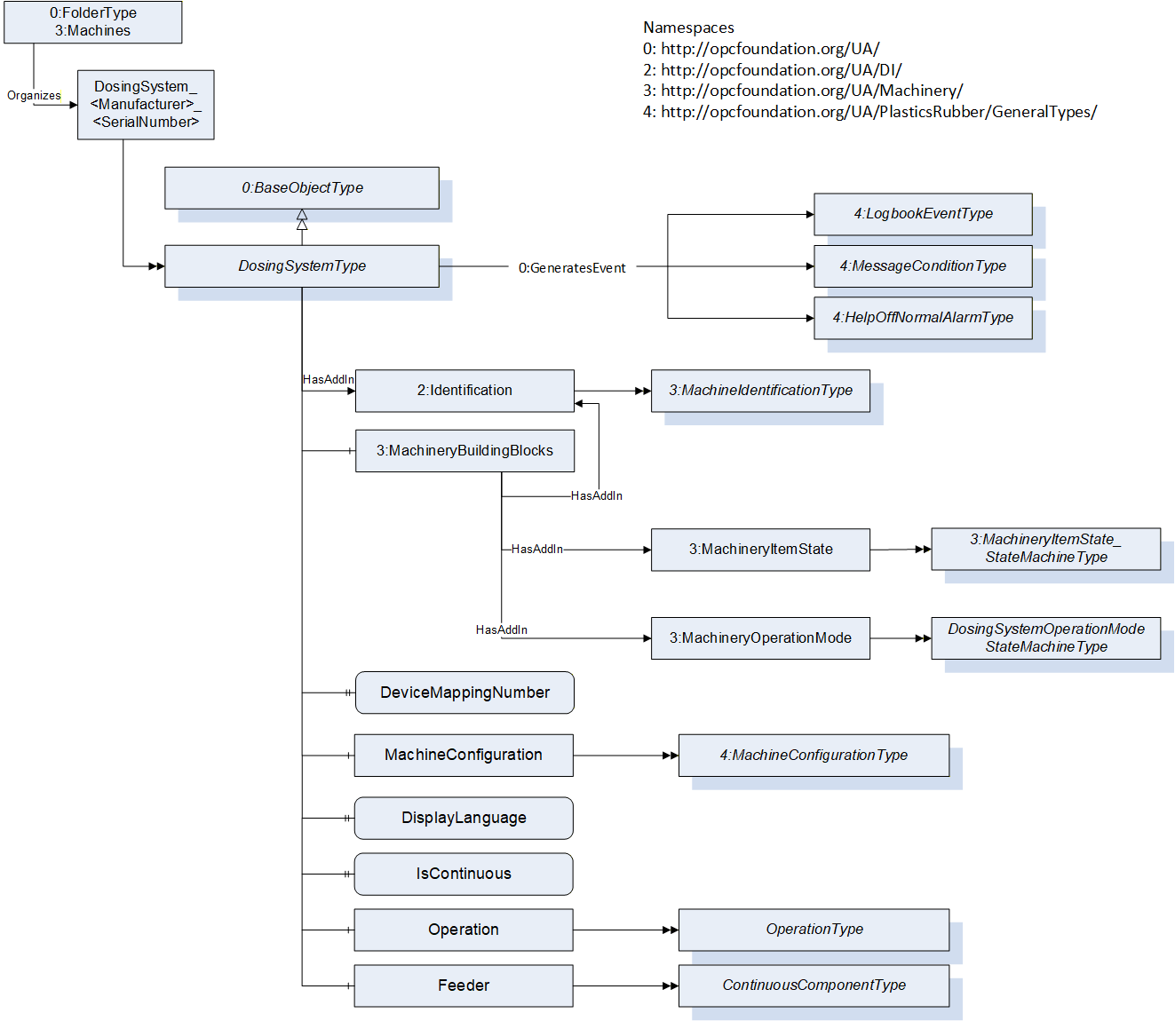
This OPC UA ObjectType is used for the root Object representing a dosing system as part of a production cell/line. It is formally defined in Table 1.
The instance(s) of DosingSystemType shall be located under the Machines Object of the Server (see OPC UA for Machinery).
| Attribute | Value | ||||
| BrowseName | DosingSystemType | ||||
| IsAbstract | False | ||||
| References | Node Class | BrowseName | DataType | TypeDefinition | Other |
|---|---|---|---|---|---|
| Subtype of the 0:BaseObjectType defined in OPC 10000-5 | |||||
| 0:HasAddIn | Object | 2:Identification | 3:MachineIdentification Type | M | |
| 0:HasComponent | Object | 3:MachineryBuildingBlocks | 0:FolderType | M | |
| 0:HasComponent | Object | MachineConfiguration | 4:MachineConfigurationType | M | |
| 0:HasProperty | Variable | DisplayLanguage | 0:LocaleId | 0:PropertyType | O, RW |
| 0:HasProperty | Variable | IsContinuous | 0:Boolean | 0:PropertyType | M, RO |
| 0:HasComponent | Object | Operation | OperationType | M | |
| 0:HasProperty | Variable | DeviceMappingNumber | 0:UInt32 | 0:PropertyType | M, RW |
| 0:HasComponent | Object | Feeder | ContinuousComponentType | O | |
| 0:GeneratesEvent | ObjectType | 4:LogbookEventType | Defined in OPC 40083 | ||
| 0:GeneratesEvent | ObjectType | 4:MessageConditionType | Defined in OPC 40083 | ||
| 0:GeneratesEvent | ObjectType | 4:HelpOffNormalAlarmType | Defined in OPC 40083 | ||
| Conformance Units | |||||
|---|---|---|---|---|---|
| OPC 40082-4 Basic | |||||
| OPC 40082-4 Alarms |
7.2 Identification and MachineryBuildingBlocks
The MachineIdentificationType is defined in OPC UA for Machinery (OPC 40001-1) and provides basic information on a machine/device.
For the InstanceDeclaration the ModellingRules of the Properties Model and DeviceClass are overridden to mandatory.
The Object MachineryBuildingBlocks contains building blocks from OPC UA for Machinery as defined in OPC 40001-1. For this version of OPC 40082-4, the Object uses the two AddIns MachineryItemState and MachineryOperationMode.
| BrowsePath | References | NodeClass | BrowseName | DataType | TypeDefinition | Other |
| 2:Identification | 0:HasProperty | Variable | 2:Model | 0:LocalizedText | 0:PropertyType | M, RO |
| 2:Identification | 0:HasProperty | Variable | 2:DeviceClass | 0:String | 0:PropertyType | M, RO |
| 3:MachineryBuildingBlocks | 0:HasAddIn | Object | 3:MachineryItemState | 3:MachineryItemState_StateMachineType | M | |
| 3:MachineryBuildingBlocks | 0:HasAddIn | Object | 3:MachineryOperationMode | 3:MachineryOperationModeStateMachineType | M |
The DeviceClass Property shall have the value "Dosing System".
The components of the DosingSystemType have additional references which are defined in Table 3.
| SourceBrowsePath | Reference Type | Is Forward | TargetBrowsePath |
| 3:MachineryBuildingBlocks | 0:HasAddIn | True | 2:Identification |
7.2.1 Machine State and Operation Mode
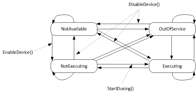
To provide the machine state, this specification uses the AddIn MachineryItemState from OPC 40001-1. Different Methods defined in this specification non-exclusively trigger state transitions, meaning that the server can also trigger these transitions in other ways (e.g. HMI input, control logic…):
EnableDevice (defined in 8.5) triggers the transition from NotAvailable to NotExecuting by e.g. switching on the drives of the device. NotExecuting means, the dosing device is ready for dosing and waiting for a dosing signal.
DisableDevice (defined in 8.6) triggers the transition from any state to NotAvailable by e.g. switching off the drives of the device. Further SubStates like e.g. "sleep", "energy saving", "eco mode" or "off" are not defined in this specification.
StartDosing (defined in 8.7) triggers the transition from NotExecuting to Executing if RemoteControlActivated (defined in ) is in mode "OPC UA" (2). If not, the transition is performed by the server.
The transition from Executing state to any other state can be triggered in different ways depending on the application, e.g. automatically by the server in IMM application after each cycle or by the methods StopDosing or StopDosingAfterCycle in case of continuous dosing.
Figure 3 gives an overview of the machine state, transitions and methods.
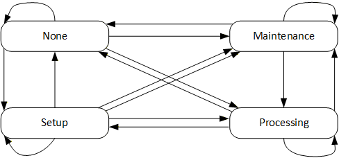
For the operation modes, the MachineryOperationMode state machine is used without changes:
7.3 DeviceMappingNumber
| Description: | Unique identifier/address/number for devices of the same DeviceType within a local network. Several peripheral devices of the same DeviceType can be connected to a production machine (e.g. IMM or extruder). In most applications, the production machine must map the connected peripheral devices to internal logical devices and zones in a fixed configuration (e.g. hot runner systems according to the wiring or temperature control devices according to the tubing). |
The mapping shall be stable after reconnecting the devices and is therefore not possible via IP addresses, which can be assigned dynamically via DHCP. DeviceMappingNumber sets the mapping order of peripheral devices of the same type on the local network and is therefore of type UInt32.
| Example: | 1 |
7.4 MachineConfiguration
The MachineConfiguration Object represents the current configuration of the Dosing System. The MachineConfigurationType is defined in OPC 40083.
7.5 DisplayLanguage
With the DisplayLanguage Property the client can set the desired language on the user interface at the Dosing System. If the peripheral device does not support the configured language, it can keep the previous setting or use English as the default.
7.6 IsContinuous
The dosing device can be installed on an extruder (EXT) or an injection moulding machine (IMM). EXT is a continuous process, IMM is a cyclic process. For inline dosing devices, directly mounted on the feed throat of an IMM the IsContinuous flag is false, when installed on an EXT this flag is true.
For batch blenders which are cyclic based by themselves, this flag is set true since the output flow of a batch blender does not need to be synchronized with for example an IMM.
7.7 Operation
This ObjectType contains parameters which are necessary to operate the Dosing System. The OperationType is defined in chapter 8.
7.8 Feeder
A feeder can be used for starve feeding (under feeding) of a production machine and is defined by the ContinuousComponentType. E.g. a screw feeder where DosingMode is set to ONLY_CONVEYING. The ContinuousComponentType is defined in chapter11.20.