
1 Scope
This specification contains modelling concepts used in industrial automation.
This version of the specification contains modelling concepts for:
Stacklights
Statistical Data
Calibration Target Management
2 Normative references
The following referenced documents are indispensable for the application of this OPC UA part. For dated references, only the edition cited applies. For undated references, the latest edition of the referenced document (including any amendments and errata) applies.
OPC 10000-1, OPC Unified Architecture - Part 1: Overview and Concepts
http://www.opcfoundation.org/documents/10000-1/
OPC 10000-3, OPC Unified Architecture - Part 3: Address Space Model
http://www.opcfoundation.org/documents/10000-3/
OPC 10000-4, OPC Unified Architecture - Part 4: Services
http://www.opcfoundation.org/documents/10000-4/
OPC 10000-5, OPC Unified Architecture - Part 5: Information Model
http://www.opcfoundation.org/documents/10000-5/
OPC 10000-6, OPC Unified Architecture - Part 6: Mappings
http://www.opcfoundation.org/documents/10000-6/
OPC 10000-7, OPC Unified Architecture - Part 7: Profiles
http://www.opcfoundation.org/documents/10000-7/
OPC 10000-8, OPC Unified Architecture - Part 8: Data Access
http://www.opcfoundation.org/documents/10000-8/
OPC 10000-100, OPC Unified Architecture - Part 100: Devices
http://www.opcfoundation.org/documents/10000-100/
IEC 60073, Basic and Safety Principles for Man-Machine Interface, Marking and Identification - Coding Principles for Indicators and Actuators
RFC 3986, Uniform Resource Identifier (URI): Generic Syntax:
3 Terms, definitions, abbreviated terms, and conventions
3.1 Terms and definitions
For the purposes of this document, the terms and definitions given in OPC 10000-1, OPC 10000-3, OPC 10000-4, OPC 10000-5, OPC 10000-6, OPC 10000-7, OPC 10000-8, and OPC 10000-100 apply.
All used terms are italicized in this document.
3.2 Abbreviated terms
| UA | Unified Architecture |
3.3 Conventions used in this document
3.3.1 Conventions for Node descriptions
Node definitions are specified using tables (see Table 2).
Attributes are defined by providing the Attribute name and a value, or a description of the value.
References are defined by providing the ReferenceType name, the BrowseName of the TargetNode and its NodeClass.
If the TargetNode is a component of the Node being defined in the table the Attributes of the composed Node are defined in the same row of the table.
The DataType is only specified for Variables; "[<number>]" indicates a single-dimensional array, for multi-dimensional arrays the expression is repeated for each dimension (e.g. [2][3] for a two-dimensional array). For all arrays the ArrayDimensions is set as identified by <number> values. If no <number> is set, the corresponding dimension is set to 0, indicating an unknown size. If no number is provided at all the ArrayDimensions can be omitted. If no brackets are provided, it identifies a scalar DataType and the ValueRank is set to the corresponding value (see OPC 10000-3). In addition, ArrayDimensions is set to null or is omitted. If it can be Any or ScalarOrOneDimension, the value is put into "{<value>}", so either "{Any}" or "{ScalarOrOneDimension}" and the ValueRank is set to the corresponding value (see OPC 10000-3) and the ArrayDimensions is set to null or is omitted. Examples are given in Table 1.
| Notation | DataType | ValueRank | ArrayDimensions | Description |
| 0:Int32 | 0:Int32 | -1 | omitted or null | A scalar Int32. |
| 0:Int32[] | 0:Int32 | 1 | omitted or {0} | Single-dimensional array of Int32 with an unknown size. |
| 0:Int32[][] | 0:Int32 | 2 | omitted or {0,0} | Two-dimensional array of Int32 with unknown sizes for both dimensions. |
| 0:Int32[3][] | 0:Int32 | 2 | {3,0} | Two-dimensional array of Int32 with a size of 3 for the first dimension and an unknown size for the second dimension. |
| 0:Int32[5][3] | 0:Int32 | 2 | {5,3} | Two-dimensional array of Int32 with a size of 5 for the first dimension and a size of 3 for the second dimension. |
| 0:Int32{Any} | 0:Int32 | -2 | omitted or null | An Int32 where it is unknown if it is scalar or array with any number of dimensions. |
| 0:Int32{ScalarOrOneDimension} | 0:Int32 | -3 | omitted or null | An Int32 where it is either a single-dimensional array or a scalar. |
The TypeDefinition is specified for Objects and Variables.
The TypeDefinition column specifies a symbolic name for a NodeId, i.e. the specified Node points with a HasTypeDefinition Reference to the corresponding Node.
The ModellingRule of the referenced component is provided by specifying the symbolic name of the rule in the ModellingRule column. In the AddressSpace, the Node shall use a HasModellingRule Reference to point to the corresponding ModellingRule Object.
If the NodeId of a DataType is provided, the symbolic name of the Node representing the DataType shall be used.
Note that if a symbolic name of a different namespace is used, it is prefixed by the NamespaceIndex (see Table 73).
Nodes of all other NodeClasses cannot be defined in the same table; therefore, only the used ReferenceType, their NodeClass and their BrowseName are specified. A reference to another part of this document points to their definition.
Table 2 illustrates the table. If no components are provided, the DataType, TypeDefinition and Other columns may be omitted and only a Comment column is introduced to point to the Node definition.
| Attribute | Value | ||||
| Attribute name | Attribute value. If it is an optional Attribute that is not set "--" is used. | ||||
| References | NodeClass | BrowseName | DataType | TypeDefinition | Other |
|---|---|---|---|---|---|
| ReferenceType name | NodeClass of the TargetNode. | BrowseName of the target Node. If the Reference is to be instantiated by the server, then the value of the target Node's BrowseName is "--". | DataType of the referenced Node, only applicable for Variables. | TypeDefinition of the referenced Node, only applicable for Variables and Objects. | Additional characteristics of the TargetNode such as the ModellingRule or AccessLevel. |
| NOTE Notes referencing footnotes of the table content. | |||||
Components of Nodes can be complex that is containing components by themselves. The TypeDefinition, NodeClass and DataType can be derived from the type definitions, and the symbolic name can be created as defined in Annex A. Therefore, those containing components are not explicitly specified; they are implicitly specified by the type definitions.
The Other column defines additional characteristics of the Node. Examples of characteristics that can appear in this column are show in Table 3.
| Name | Short Name | Description |
| 0:Mandatory | M | The Node has the Mandatory ModellingRule. |
| 0:Optional | O | The Node has the Optional ModellingRule. |
| 0:MandatoryPlaceholder | MP | The Node has the MandatoryPlaceholder ModellingRule. |
| 0:OptionalPlaceholder | OP | The Node has the OptionalPlaceholder ModellingRule. |
| ReadOnly | RO | The Node AccessLevel has the CurrentRead bit set but not the CurrentWrite bit. |
| ReadWrite | RW | The Node AccessLevel has the CurrentRead and CurrentWrite bits set. |
| WriteOnly | WO | The Node AccessLevel has the CurrentWrite bit set but not the CurrentRead bit. |
If multiple characteristics are defined, they are separated by commas. The name or the short name may be used.
3.3.1.1 Additional References
To provide information about additional References, the format as shown in Table 4 is used.
| SourceBrowsePath | Reference Type | Is Forward | TargetBrowsePath |
| SourceBrowsePath is always relative to the TypeDefinition. Multiple elements are defined as separate rows of a nested table. | ReferenceType name | True = forward Reference. | TargetBrowsePath points to another Node, which can be a well-known instance or a TypeDefinition. You can use BrowsePaths here as well, which is either relative to the TypeDefinition or absolute. If absolute, the first entry needs to refer to a type or well-known instance, uniquely identified within a namespace by the BrowseName. |
References can be to any other Node.
3.3.1.2 Additional sub-components
To provide information about sub-components, the format as shown in Table 5 is used.
| BrowsePath | References | NodeClass | BrowseName | DataType | TypeDefinition | Others |
| BrowsePath is always relative to the TypeDefinition. Multiple elements are defined as separate rows of a nested table | NOTE Same as for Table 2 | |||||
3.3.1.3 Additional Attribute values
The type definition table provides columns to specify the values for required Node Attributes for InstanceDeclarations. To provide information about additional Attributes, the format as shown in Table 6 is used.
| BrowsePath | <Attribute name> Attribute |
| BrowsePath is always relative to the TypeDefinition. Multiple elements are defined as separate rows of a nested table | The values of attributes are converted to text by adapting the reversible JSON encoding rules defined in OPC 10000-6. If the JSON encoding of a value is a JSON string or a JSON number then that value is entered in the value field. Double quotes are not included. If the DataType includes a NamespaceIndex (QualifiedNames, NodeIds or ExpandedNodeIds) then the notation used for BrowseNames is used. If the value is an Enumeration the name of the enumeration value is entered. If the value is a Structure then a sequence of name and value pairs is entered. Each pair is followed by a newline. The name is followed by a colon. The names are the names of the fields in the DataTypeDefinition. If the value is an array of non-structures then a sequence of values is entered where each value is followed by a newline. If the value is an array of Structures or a Structure with fields that are arrays or with nested Structures then the complete JSON array or JSON object is entered. Double quotes are not included. |
There can be multiple columns to define more than one Attribute.
3.3.2 NodeIds and BrowseNames
3.3.2.1 NodeIds
The NodeIds of all Nodes described in this standard are only symbolic names. Annex A defines the actual NodeIds.
The symbolic name of each Node defined in this document is its BrowseName, or, when it is part of another Node, the BrowseName of the other Node, a ".", and the BrowseName of itself. In this case "part of" means that the whole has a HasProperty or HasComponent Reference to its part. Since all Nodes not being part of another Node have a unique name in this document, the symbolic name is unique.
The NamespaceUri for all NodeIds defined in this document is defined in Annex A. The NamespaceIndex for this NamespaceUri is vendor-specific and depends on the position of the NamespaceUri in the server namespace table.
Note that this document not only defines concrete Nodes, but also requires that some Nodes shall be generated, for example one for each Session running on the Server. The NodeIds of those Nodes are Server-specific, including the namespace. But the NamespaceIndex of those Nodes cannot be the NamespaceIndex used for the Nodes defined in this document, because they are not defined by this document but generated by the Server.
3.3.2.2 BrowseNames
The text part of the BrowseNames for all Nodes defined in this document is specified in the tables defining the Nodes. The NamespaceUri for all BrowseNames defined in this document is defined in Annex A.
For InstanceDeclarations of NodeClass Object and Variable that are placeholders (OptionalPlaceholder and MandatoryPlaceholder ModellingRule), the BrowseName and the DisplayName are enclosed in angle brackets (<>) as recommended in OPC 10000-3. If the BrowseName is not defined by this document, a namespace index prefix is added to the BrowseName (e.g., prefix '0' leading to '0:EngineeringUnits' or prefix '2' leading to '2:DeviceRevision'). This is typically necessary if a Property of another specification is overwritten or used in the OPC UA types defined in this document. Table 73 provides a list of namespaces and their indexes as used in this document.
3.3.3 Common Attributes
3.3.3.1 General
The Attributes of Nodes, their DataTypes and descriptions are defined in OPC 10000-3. Attributes not marked as optional are mandatory and shall be provided by a Server. The following tables define if the Attribute value is defined by this document or if it is server-specific.
For all Nodes specified in this document, the Attributes named in Table 7 shall be set as specified in the table.
| Attribute | Value |
| DisplayName | The DisplayName is a LocalizedText. Each server shall provide the DisplayName identical to the BrowseName of the Node for the LocaleId "en". Whether the server provides translated names for other LocaleIds are server-specific. |
| Description | Optionally a server-specific description is provided. |
| NodeClass | Shall reflect the NodeClass of the Node. |
| NodeId | The NodeId is described by BrowseNames as defined in 3.3.2.1. |
| WriteMask | Optionally the WriteMask Attribute can be provided. If the WriteMask Attribute is provided, it shall set all non-server-specific Attributes to not writable. For example, the Description Attribute may be set to writable since a Server may provide a server-specific description for the Node. The NodeId shall not be writable, because it is defined for each Node in this document. |
| UserWriteMask | Optionally the UserWriteMask Attribute can be provided. The same rules as for the WriteMask Attribute apply. |
| RolePermissions | Optionally server-specific role permissions can be provided. |
| UserRolePermissions | Optionally the role permissions of the current Session can be provided. The value is server-specific and depends on the RolePermissions Attribute (if provided) and the current Session. |
| AccessRestrictions | Optionally server-specific access restrictions can be provided. |
3.3.3.2 Objects
For all Objects specified in this document, the Attributes named in Table 8 shall be set as specified in the Table 8. The definitions for the Attributes can be found in OPC 10000-3.
| Attribute | Value |
| EventNotifier | Whether the Node can be used to subscribe to Events or not is server-specific. |
3.3.3.3 Variables
For all Variables specified in this document, the Attributes named in Table 9 shall be set as specified in the table. The definitions for the Attributes can be found in OPC 10000-3.
| Attribute | Value |
| MinimumSamplingInterval | Optionally, a server-specific minimum sampling interval is provided. |
| AccessLevel | The access level for Variables used for type definitions is server-specific, for all other Variables defined in this document, the access level shall allow reading; other settings are server-specific. |
| UserAccessLevel | The value for the UserAccessLevel Attribute is server-specific. It is assumed that all Variables can be accessed by at least one user. |
| Value | For Variables used as InstanceDeclarations, the value is server-specific; otherwise it shall represent the value described in the text. |
| ArrayDimensions | If the ValueRank does not identify an array of a specific dimension (i.e. ValueRank <= 0) the ArrayDimensions can either be set to null or the Attribute is missing. This behaviour is server-specific. If the ValueRank specifies an array of a specific dimension (i.e. ValueRank > 0) then the ArrayDimensions Attribute shall be specified in the table defining the Variable. |
| Historizing | The value for the Historizing Attribute is server-specific. |
| AccessLevelEx | If the AccessLevelEx Attribute is provided, it shall have the bits 8, 9, and 10 set to 0, meaning that read and write operations on an individual Variable are atomic, and arrays can be partly written. |
3.3.3.4 VariableTypes
For all VariableTypes specified in this document, the Attributes named in Table 10 shall be set as specified in the table. The definitions for the Attributes can be found in OPC 10000-3.
| Attributes | Value |
| Value | Optionally a server-specific default value can be provided. |
| ArrayDimensions | If the ValueRank does not identify an array of a specific dimension (i.e. ValueRank <= 0) the ArrayDimensions can either be set to null or the Attribute is missing. This behaviour is server-specific. If the ValueRank specifies an array of a specific dimension (i.e. ValueRank > 0) then the ArrayDimensions Attribute shall be specified in the table defining the VariableType. |
3.3.3.5 Methods
For all Methods specified in this document, the Attributes named in Table 11 shall be set as specified in the table. The definitions for the Attributes can be found in OPC 10000-3.
| Attributes | Value |
| Executable | All Methods defined in this document shall be executable (Executable Attribute set to "True"), unless it is defined differently in the Method definition. |
| UserExecutable | The value of the UserExecutable Attribute is server-specific. It is assumed that all Methods can be executed by at least one user. |
4 Concept
This specification contains modelling concepts for industrial automation. The concepts can be used independent of each other and are organized in individual sections.
5 Stacklights
5.1 Overview
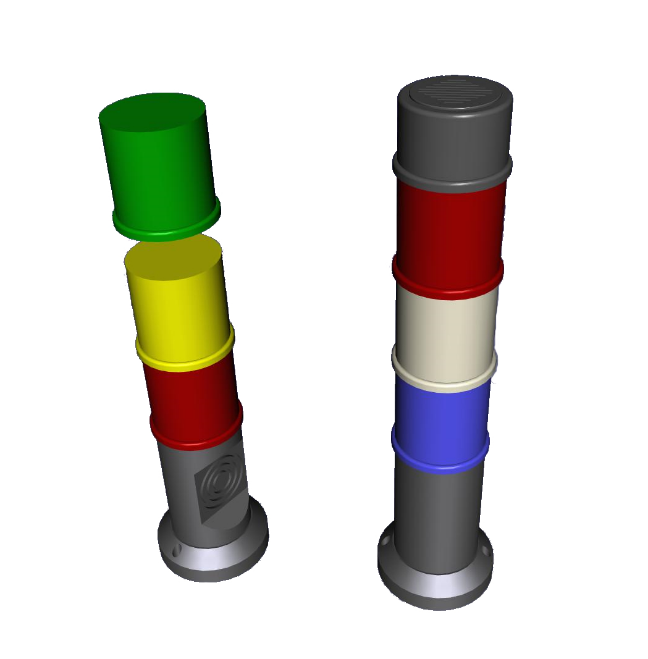
A stacklight is used to visually or acoustically indicate the state or a specific event of an automation component. It is widely used in various areas of industrial automation. In Figure 1, examples of stacklights are given. They can vary in colours they display or acoustical signals they produce.
This section defines base modelling constructs to represent stacklights in an OPC UA Information Model. It does not define the relations to the triggers of a specific visualization or acoustic signal, like an Alarm or a specific Value of a Variable.
5.2 OPC UA ObjectTypes
5.2.1 BasicStacklightType
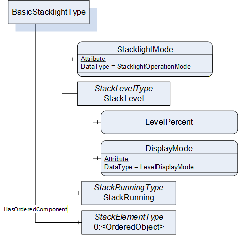
The BasicStacklightType is the entry point to a stacklight. It contains the elements of the stacklight as well as additional information valid for the whole unit. In Figure 2, a graphical overview is given. It is formally defined in Table 12.
| Attribute | Value | ||||
| BrowseName | BasicStacklightType | ||||
| IsAbstract | False | ||||
| Description | Entry point to a stacklight containing elements of the stacklight as well as additional information valid for the whole unit. | ||||
| References | Node Class | BrowseName | DataType | TypeDefinition | Other |
|---|---|---|---|---|---|
| Subtype of the 0:OrderedListType, i.e. inheriting the InstanceDeclarations of that Node. | |||||
| 0:HasProperty | Variable | StacklightMode | StacklightOperationMode | 0:PropertyType | M |
| 0:HasComponent | Object | StackLevel | StackLevelType | O | |
| 0:HasComponent | Object | StackRunning | StackRunningType | O | |
| 0:HasOrderedComponent | Object | 0:<OrderedObject> | StackElementType | OP | |
StacklightMode shows in what way (stack of individual lights, level meter, running light) the stacklight unit is used.
StackLevel is only valid if the stacklight is used in "Levelmeter" StacklightMode. If so, the whole stack is controlled by a single percentual value. In this case, the SignalOn parameter of any <OrderedObject> of StackElementLightType has no meaning.
StackRunning is only valid if the stacklight is used in "Running_Light" StacklightMode.
The ordered component(s) <OrderedObject> represent the stack elements (lamps and acoustic elements) the stacklight is composed of. The HasOrderedComponent Reference shall represent the ordering from the base of the stacklight.
The InstanceDeclarations of the BasicStacklightType have the Attribute values defined in Table 13.
| Source Path | Value | Description |
| StacklightMode | - | Shows in what way (stack of individual lights, level meter, running light) the stacklight unit is used. |
| StackLevel | - | Valid if the stacklight is used in "Levelmeter" StacklightMode. If so, the whole stack is controlled by a single percentual value. In this case, the SignalOn parameter of any stack element of StackElementLightType has no meaning. |
| StackRunning | - | Valid if the stacklight is used in "Running_Light" StacklightMode. |
| 0:<OrderedObject> | - | Represent the stack elements (lamps and acoustic elements) the stacklight is composed of. The HasOrderedComponent Reference shall represent the ordering from the base of the stacklight. |
5.2.2 StacklightType
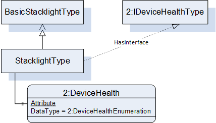
The StacklightType is a subtype of the BasicStacklightType. It adds the possibility to show the stacklight's health status. In Figure 3, a graphical overview is given. It is formally defined in Table 14.
| Attribute | Value | ||||
| BrowseName | StacklightType | ||||
| IsAbstract | False | ||||
| Description | Entry point to a stacklight with the possibility to show the stacklight's health status. | ||||
| References | Node Class | BrowseName | DataType | TypeDefinition | Other |
|---|---|---|---|---|---|
| Subtype of the BasicStacklightType defined in 5.2.1, i.e. inheriting the InstanceDeclarations of that Node. | |||||
| 0:HasInterface | ObjectType | 2:IDeviceHealthType | |||
| Properties of the 2:IDeviceHealthType | |||||
| 0:HasComponent | Variable | 2:DeviceHealth | 2:DeviceHealthEnumeration | 0:BaseDataVariableType | O |
| 0:HasComponent | Object | 2:DeviceHealthAlarms | 0:FolderType | O | |
DeviceHealth, defined in IDeviceHealthType, indicates the health status of the stacklight and shall be used as specified in OPC 10000-100.
DeviceHealthAlarms, defined in IDeviceHealthType, can be used to expose alarm instances and shall be used as specified in OPC 10000-100.
The InstanceDeclarations of the StacklightType have the Attribute values defined in Table 15.
| Source Path | Value | Description |
| 2:DeviceHealth | - | Contains the health status information of the stacklight. |
| 2:DeviceHealthAlarms | - | Contains alarms of the stacklights providing more detailed information on the health of the stacklight. |
5.2.3 StackLevelType
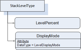
The StackLevelType contains the information relevant to a stacklight operating as a level meter. The whole stack is controlled by a percentual value. In Figure 4, a graphical overview is given. It is formally defined in Table 16.
| Attribute | Value | ||||
| BrowseName | StackLevelType | ||||
| IsAbstract | False | ||||
| Description | Contains information relevant to a stacklight operating as a level meter. The whole stack is controlled by a percentual value. | ||||
| References | Node Class | BrowseName | DataType | TypeDefinition | Other |
|---|---|---|---|---|---|
| Subtype of the 0:BaseObjectType defined in OPC 10000-5, i.e. inheriting the InstanceDeclarations of that Node. | |||||
| 0:HasComponent | Variable | LevelPercent | 0:Float | 0:AnalogItemType | M |
| 0:HasComponent | Variable | DisplayMode | LevelDisplayMode | 0:BaseDataVariableType | M |
LevelPercent shows the percentual value the stacklight is representing. The mandatory EURange Property of the Variable indicates the lowest and highest value and thereby allows to calculate the percentage represented by the value. The lowest value is interpreted as 0 percent, the highest is interpreted as 100 percent.
DisplayMode indicates in what way the percentual value is displayed with the stacklight.
The InstanceDeclarations of the StackLevelType have the Attribute values defined in Table 17.
| Source Path | Value | Description |
| LevelPercent | - | Shows the percentual value the stacklight is representing. The mandatory EURange Property of the Variable indicates the lowest and highest value and thereby allows to calculate the percentage represented by the value. The lowest value is interpreted as 0 percent, the highest is interpreted as 100 percent. |
| DisplayMode | - | Indicates in what way the percentual value is displayed with the stacklight. |
5.2.4 StackRunningType
The StackRunningType contains the information relevant to a stacklight operating as a running light. This base type does not define any specific information, but can be extended. This Object is only of relevance when the StacklightMode is in mode "Running_Light". It is formally defined in Table 18.
| Attribute | Value | ||||
| BrowseName | StackRunningType | ||||
| IsAbstract | False | ||||
| Description | Contains information relevant to a stacklight operating as a running light. This base type does not define any specific information, but can be extended. | ||||
| References | Node Class | BrowseName | DataType | TypeDefinition | Other |
|---|---|---|---|---|---|
| Subtype of the 0:BaseObjectType defined in OPC 10000-5 i.e. inheriting the InstanceDeclarations of that Node. | |||||
5.2.5 StackElementType
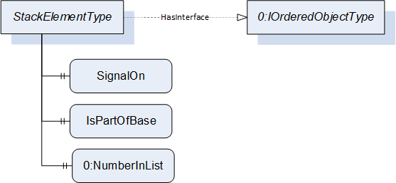
The StackElementType is the base class for elements in a stacklight. The elements are used in an ordered list. In Figure 5, a graphical overview is given. It is formally defined in Table 19.
| Attribute | Value | ||||
| BrowseName | StackElementType | ||||
| IsAbstract | True | ||||
| Description | Base class for elements in a stacklight. | ||||
| References | Node Class | BrowseName | DataType | TypeDefinition | Other |
|---|---|---|---|---|---|
| Subtype of the 0:BaseObjectType defined in OPC 10000-5 i.e. inheriting the InstanceDeclarations of that Node. | |||||
| 0:HasInterface | ObjectType | 0:IOrderedObjectType | |||
| 0:HasProperty | Variable | SignalOn | 0:Boolean | 0:PropertyType | O |
| 0:HasProperty | Variable | IsPartOfBase | 0:Boolean | 0:PropertyType | O |
| 0:HasProperty | Variable | 0:NumberInList | 0:UInteger | 0:PropertyType | M |
SignalOn indicates if the signal emitted by the stack element is currently switched on or not.
IsPartOfBase indicates, if the element is contained in the mounting base of the stacklight. All elements contained in the mounting base shall be at the beginning of the list of stack elements.
NumberInList is defined in the IOrderedObjectType and used in conjunction with the HasOrderedComponent Reference of the BasicStacklightType. It shall contain the same ordering information as the Reference and enumerate the stacklight elements counting upwards beginning from the base of the stacklight.
The InstanceDeclarations of the StackElementType have the Attribute values defined in Table 20.
| Source Path | Value | Description |
| SignalOn | - | Indicates if the signal emitted by the stack element is currently switched on or not. |
| IsPartOfBase | - | Indicates, if the element is contained in the mounting base of the stacklight. All elements contained in the mounting base shall be at the beginning of the list of stack elements. |
| 0:NumberInList | - | Enumerate the stacklight elements counting upwards beginning from the base of the stacklight. |
5.2.6 StackElementLightType
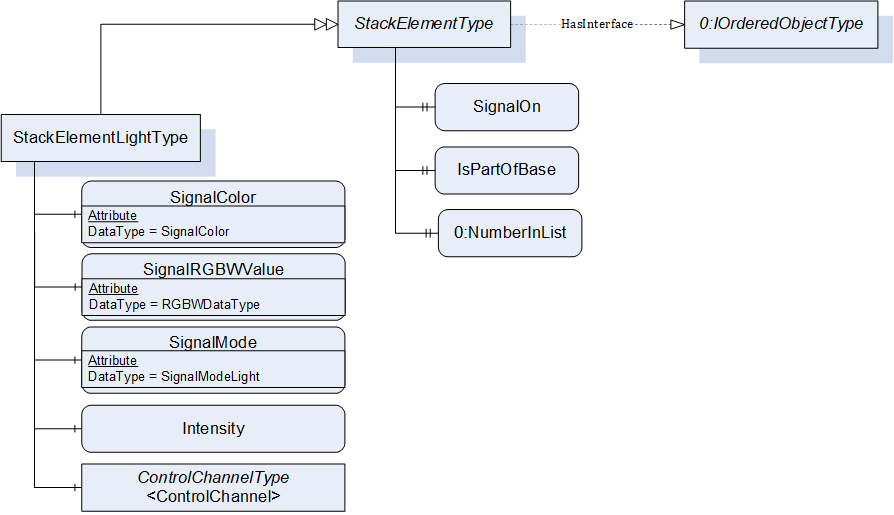
The StackElementLightType represents a lamp element in a stacklight. In Figure 6, a graphical overview is given. It is formally defined in Table 21.
| Attribute | Value | ||||
| BrowseName | StackElementLightType | ||||
| IsAbstract | False | ||||
| Description | Represents a lamp element in a stacklight. | ||||
| References | Node Class | BrowseName | DataType | TypeDefinition | Other |
|---|---|---|---|---|---|
| Subtype of the StackElementType defined in 5.2.5, i.e. inheriting the InstanceDeclarations of that Node. | |||||
| 0:HasComponent | Variable | SignalColor | SignalColor | 0:BaseDataVariableType | O |
| 0:HasComponent | Variable | SignalRGBWValue | RGBWDataType | 0:BaseDataVariableType | O |
| 0:HasComponent | Variable | SignalMode | SignalModeLight | 0:BaseDataVariableType | O |
| 0:HasComponent | Variable | Intensity | 0:Float | 0:AnalogItemType | O |
| 0:HasComponent | Object | <ControlChannel> | ControlChannelType | OP | |
For the StackElementLightType, either the Variables SignalColor, SignalOn, SignalMode and Intensity shall be used to indicate the respective values for the lamp element or separate ControlChannels per available and individually controllable colour channel shall be used (e.g. in RGB or RGBW lamp elements). The two concepts shall not be used in conjunction in a single StackElementLightType instance.
SignalColor indicates the colour the lamp element has when switched on.
The optional SignalRGBWValue provides a more precise representation of the SignalColor. It may be provided in addition to the SignalColor and shall not contradict it, i.e., it shall be at least a nearby colour of the SignalColor. The SignalRGBWValue shall not be provided when the SignalColor is not provided.
SignalMode shows in what way the lamp is used (continuous light, flashing, blinking) when switched on.
Intensity shows the intensity of the lamp, thus its brightness. The mandatory EURange Property of the Variable indicates the lowest and highest value and thereby allows to calculate the percentage represented by the value. The lowest value is interpreted as 0 percent, the highest is interpreted as 100 percent.
The list of <ControlChannel> instances shows the control information for each independent colour channel of the stacked element.
The InstanceDeclarations of the StackElementLightType have the Attribute values defined in Table 22.
| Source Path | Value | Description |
| SignalColor | - | Indicates the colour the lamp element has when switched on. |
| SignalMode | - | Shows in what way the lamp is used (continuous light, flashing, blinking) when switched on. |
| Intensity | - | Intensity of the lamp, thus its brightness. The mandatory EURange Property of the Variable indicates the lowest and highest value and thereby allows to calculate the percentage represented by the value. The lowest value is interpreted as 0 percent, the highest is interpreted as 100 percent. |
| <ControlChannel> | - | The list of <ControlChannel> instances shows the control information for each independent colour channel of the stacked element. |
5.2.7 StackElementAcousticType
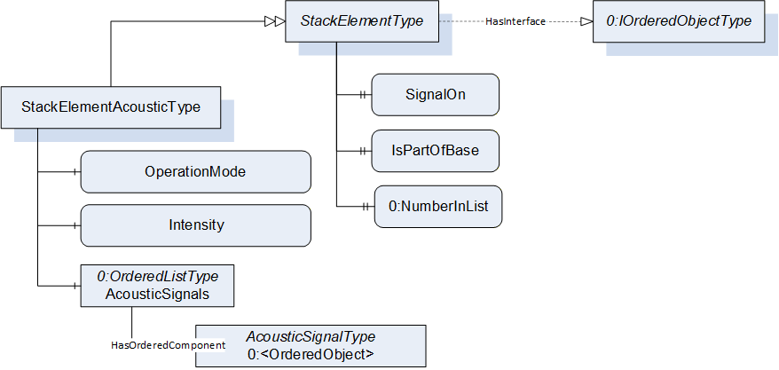
The StackElementAcousticType represents an acoustic element in a stacklight. In Figure 7, a graphical overview is given. It is formally defined in Table 23.
| Attribute | Value | ||||
| BrowseName | StackElementAcousticType | ||||
| IsAbstract | False | ||||
| Description | Represents an acoustic element in a stacklight. | ||||
| References | Node Class | BrowseName | DataType | TypeDefinition | Other |
|---|---|---|---|---|---|
| Subtype of the StackElementType defined in 5.2.5, i.e. inheriting the InstanceDeclarations of that Node. | |||||
| 0:HasComponent | Variable | OperationMode | 0:UInteger | 0:BaseDataVariableType | M |
| 0:HasComponent | Variable | Intensity | 0:Float | 0:AnalogItemType | O |
| 0:HasComponent | Object | AcousticSignals | 0:OrderedListType | M | |
OperationMode indicates what signal of the list of AcousticSignalType nodes is played when the acoustic element is switched on. It shall contain an index matching the NumberInList Property of the respective AcousticSignalType Object of AcousticSignals.
Intensity indicates the sound pressure level of the acoustic signal when switched on. This value shall only have positive values. The mandatory EURange Property of the Variable indicates the lowest and highest value and thereby allows to calculate the percentage represented by the value. The lowest value is interpreted as 0 percent, the highest is interpreted as 100 percent.
AcousticSignals contains a list of audio signals used by this acoustic stacklight element.
The components of the StackElementAcousticType have additional References which are defined in Table 24.
| Source Path | References | NodeClass | BrowseName | DataType | TypeDefinition | Others |
| AcousticSignals | 0:HasOrderedComponent | Object | 0:<OrderedObject> | AcousticSignalType | MP |
The InstanceDeclarations of the StackElementAcousticType have the Attribute values defined in Table 25.
| Source Path | Value | Description | ||
| OperationMode | - | Indicates what signal of the list of AcousticSignalType nodes is played when the acoustic element is switched on. It shall contain an index into the NumberInList of the respective AcousticSignalType Object of AcousticSignals. | ||
| Intensity | - | Indicates the sound pressure level of the acoustic signal when switched on. This value shall only have positive values. The mandatory EURange Property of the Variable indicates the lowest and highest value and thereby allows to calculate the percentage represented by the value. The lowest value is interpreted as 0 percent, the highest is interpreted as 100 percent. | ||
| AcousticSignals | - | Contains a list of audio signals used by this acoustic stacklight element. | ||
| - | Represents an acoustic signal. |
5.2.8 ControlChannelType
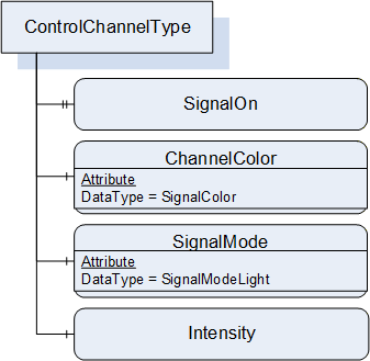
The ControlChannelType is used for control channels of single colour elements within a stack element (e.g. RGB elements would use three ControlChannels, one for each controllable colour). In Figure 8, a graphical overview is given. It is formally defined in Table 26.
| Attribute | Value | ||||
| BrowseName | ControlChannelType | ||||
| IsAbstract | False | ||||
| Description | Used for control channels of single colour elements within a stack element (e.g. RGB elements would use three ControlChannels, one for each controllable colour). | ||||
| References | Node Class | BrowseName | DataType | TypeDefinition | Other |
|---|---|---|---|---|---|
| Subtype of the 0:BaseObjectType defined in OPC 10000-5 i.e. inheriting the InstanceDeclarations of that Node. | |||||
| 0:HasProperty | Variable | SignalOn | 0:Boolean | 0:PropertyType | M |
| 0:HasComponent | Variable | ChannelColor | SignalColor | 0:BaseDataVariableType | M |
| 0:HasComponent | Variable | SignalMode | SignalModeLight | 0:BaseDataVariableType | M |
| 0:HasComponent | Variable | Intensity | 0:Float | 0:AnalogItemType | O |
SignalOn indicates if the colour is switched on.
ChannelColor shows the channel's colour.
SignalMode indicates in what mode (continuously on, blinking, flashing) the channel operates when switched on.
Intensity shows the channel's intensity, thus its brightness. The mandatory EURange Property of the Variable indicates the lowest and highest value and thereby allows to calculate the percentage represented by the value. The lowest value is interpreted as 0 percent, the highest is interpreted as 100 percent.
The InstanceDeclarations of the ControlChannelType have the Attribute values defined in Table 27.
| Source Path | Value | Description |
| SignalOn | - | Indicates if the colour is switched on. |
| ChannelColor | - | Indicates in what mode (continuously on, blinking, flashing) the channel operates when switched on. |
| SignalMode | - | Contains a list of audio signals used by this acoustic stacklight element. |
| Intensity | - | Shows the channel's intensity, thus its brightness. The mandatory EURange Property of the Variable indicates the lowest and highest value and thereby allows to calculate the percentage represented by the value. The lowest value is interpreted as 0 percent, the highest is interpreted as 100 percent. |
5.2.9 AcousticSignalType
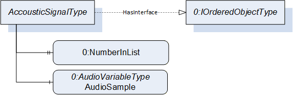
The AcousticSignalType represents an acoustic signal. It is used in an ordered list. In Figure 9, a graphical overview is given. It is formally defined in Table 28.
| Attribute | Value | ||||
| BrowseName | AcousticSignalType | ||||
| IsAbstract | False | ||||
| Description | Represents an acoustic signal. | ||||
| References | Node Class | BrowseName | DataType | TypeDefinition | Other |
|---|---|---|---|---|---|
| Subtype of the 0:BaseObjectType defined in OPC 10000-5, i.e. inheriting the InstanceDeclarations of that Node. | |||||
| 0:HasInterface | ObjectType | 0:IOrderedObjectType | |||
| 0:HasProperty | Variable | 0:NumberInList | 0:UInteger | 0:PropertyType | M |
| 0:HasComponent | Variable | AudioSample | 0:AudioDataType | 0:BaseDataVariableType | O |
The Description Attribute of each Object of type AcousticSignalType should be used as textual description of the audio signal, e.g. "Buzzer 100Hz".
NumberInList is defined in IOrderedObjectType and used in conjunction with the HasOrderedComponent Reference of the AcousticSignals Object. Instances of StackElementAcousticType index into this number using the OperationMode Property.
AudioSample contains the audio data, e.g. for devices capable of audio playback.
The InstanceDeclarations of the AcousticSignalType have the Attribute values defined in Table 29.
| Source Path | Value | Description |
| 0:NumberInList | - | Enumerate the acoustic signals. Instances of StackElementAcousticType index into this number using the OperationMode Property. |
| AudioSample | - | Contains the audio data, e.g. for devices capable of audio playback. |
5.3 OPC UA DataTypes
5.3.1 StacklightOperationMode
The StacklightOperationMode Enumeration DataType contains the values used to indicate how a stacklight (as a whole unit) is used. The contents of its EnumStrings are defined in Table 30.
| Name | Value | Description |
|---|---|---|
| Segmented | 0 | Stacklight is used as stack of individual lights |
| Levelmeter | 1 | Stacklight is used as level meter |
| Running_Light | 2 | The whole stack acts as a running light |
| Other | 3 | Stacklight is used in a way not defined in this version of the specification |
Its representation in the AddressSpace is defined in Table 31.
| Attribute | Value | |||||
| BrowseName | StacklightOperationMode | |||||
| IsAbstract | False | |||||
| Description | Contains the values used to indicate how a stacklight (as a whole unit) is used. | |||||
| References | NodeClass | BrowseName | DataType | TypeDefinition | Other | |
|---|---|---|---|---|---|---|
| Subtype of the 0:Enumeration type defined in OPC 10000-3 | ||||||
| 0:HasProperty | Variable | 0:EnumValues | 0:EnumValueType[] | 0:PropertyType | ||
5.3.2 LevelDisplayMode
The LevelDisplayMode Enumeration DataType contains the values used to indicate how a percentual value is displayed if the stacklight unit works in Levelmeter mode. The contents of its EnumStrings are defined in Table 32.
| Name | Value | Description |
|---|---|---|
| Dimmed | 0 | Uses dimming to display fractions. |
| Blinking | 1 | Uses blinking to display fractions. |
| Other | 2 | Display fractions in a way not defined in this version of the specification. |
Its representation in the AddressSpace is defined in Table 33.
| Attribute | Value | |||||
| BrowseName | LevelDisplayMode | |||||
| IsAbstract | False | |||||
| Description | Contains the values used to indicate how a percentual value is displayed if the stacklight unit works in Levelmeter mode. | |||||
| References | NodeClass | BrowseName | DataType | TypeDefinition | Other | |
|---|---|---|---|---|---|---|
| Subtype of the 0:Enumeration type defined in OPC 10000-3 | ||||||
| 0:HasProperty | Variable | 0:EnumValues | 0:EnumValueType[] | 0:PropertyType | ||
5.3.3 SignalColor
The SignalColor Enumeration DataType holds the possible colour values for stacklight lamps. The contents of its EnumStrings are defined in Table 34.
| Name | Value | Description |
|---|---|---|
| Off | 0 | Element is disabled. |
| Red | 1 | This value indicates a red lamp colour. |
| Green | 2 | This value indicates a green lamp colour. |
| Blue | 3 | This value indicates a blue lamp colour. |
| Yellow | 4 | This value indicates a yellow lamp colour (R+G). |
| Purple | 5 | This value indicates a purple lamp colour (R+B). |
| Cyan | 6 | This value indicates a cyan lamp colour (G+B). |
| White | 7 | This value indicates a white lamp colour (R+G+B). |
Its representation in the AddressSpace is defined in Table 35.
| Attribute | Value | |||||
| BrowseName | SignalColor | |||||
| IsAbstract | False | |||||
| Description | Holds the possible colour values for stacklight lamps. | |||||
| References | NodeClass | BrowseName | DataType | TypeDefinition | Other | |
|---|---|---|---|---|---|---|
| Subtype of the 0:Enumeration type defined in OPC 10000-3 | ||||||
| 0:HasProperty | Variable | 0:EnumValues | 0:EnumValueType[] | 0:PropertyType | ||
5.3.4 SignalModeLight
SignalModeLight contains the values used to indicate in what way a lamp behaves when switched on. The contents of its EnumStrings are defined in Table 36.
| Name | Value | Description |
|---|---|---|
| Continuous | 0 | This value indicates a continuous light. |
| Blinking | 1 | This value indicates a blinking light (blinking in regular intervals with equally long on and off times). |
| Flashing | 2 | This value indicates a flashing light (blinking in intervals with longer off times than on times, per interval multiple on times are possible). |
| Other | 3 | The light is handled in a way not defined in this version of the specification. |
Its representation in the AddressSpace is defined in Table 37.
| Attribute | Value | |||||
| BrowseName | SignalModeLight | |||||
| IsAbstract | False | |||||
| Description | Contains the values used to indicate in what way a lamp behaves when switched on. | |||||
| References | NodeClass | BrowseName | DataType | TypeDefinition | Other | |
|---|---|---|---|---|---|---|
| Subtype of the Enumeration type defined in OPC 10000-3 | ||||||
| 0:HasProperty | Variable | 0:EnumValues | 0:EnumValueType[] | 0:PropertyType | ||
5.3.5 RGBWDataType
This structure represents a colour in RGB or RGBW. The structure is defined in Table 38.
| Name | Type | Description | Optional |
|---|---|---|---|
| RGBWDataType | structure | ||
Red | 0:Byte | Defines the intensity of the colour red | False |
Green | 0:Byte | Defines the intensity of the colour green | False |
Blue | 0:Byte | Defines the intensity of the colour blue | False |
White | 0:Byte | Defines the intensity of an additional white component. Shall be not provided when using RGB. | True |
Its representation in the AddressSpace is defined in Table 39.
| Attribute | Value | |||||
| BrowseName | RGBWDataType | |||||
| IsAbstract | False | |||||
| References | NodeClass | BrowseName | DataType | TypeDefinition | Other | |
|---|---|---|---|---|---|---|
| Subtype of 0:Structure | ||||||
6 Statistical Data
6.1 Overview
The Interfaces defined in this chapter can be used to manage statistical data. It provides an infrastructure to manage the statistical data, but no concrete statistical data are defined in this chapter.
6.2 OPC UA ObjectTypes
6.2.1 IStatisticsType
6.2.1.1 Overview
The IStatisticsType is an Interface to manage statistical data of any kind, and provides general information about those statistical data.
The concrete statistical data are managed in DataVariables referenced from the Object or ObjectType implementing the Interface with a HasStatisticComponent Reference, either directly or indirectly. Those Variables are not predefined by the Interface, but added by the concrete Objects or ObjectTypes implementing the Interface. In Figure 10, an example is given. The MyStatisticsType is implementing IStatisticsType and provides the statistical Variables StatVar_A and its sub-variable StatVar_A1, as well as StatX and StatY, groups by the Object StatGroup. The Property StartTime applies to all of them, as well as the Method ResetStatistics.
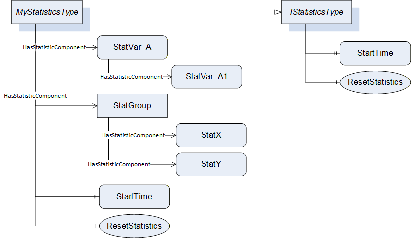
IStatisticsType is formally defined in Table 40.
| Attribute | Value | ||||
| BrowseName | IStatisticsType | ||||
| IsAbstract | True | ||||
| Description | Base interface for managing statistical data. | ||||
| References | Node Class | BrowseName | DataType | TypeDefinition | Other |
|---|---|---|---|---|---|
| Subtype of the 0:BaseInterfaceType defined in OPC 10000-5 i.e. inheriting the InstanceDeclarations of that Node. | |||||
| 0:HasProperty | Variable | StartTime | 0:DateTime | 0:PropertyType | O |
| 0:HasComponent | Method | ResetStatistics | O | ||
StartTime provides the information, at what point in time all statistical data, provided by the Object implementing the Interface, have been started to be collected. The StartTime changes when the collection of the statistical data is reset.
Note that the StartTime does not indicate, if the statistical data is aggregated from the start time, or rolled over after some specific condition. This is defined by subtypes of the IStatisticsType. Therefore, it is recommended not to use the IStatisticsType directly, but only subtypes of it.
The InstanceDeclarations of the IStatisticsType have the Attribute values defined in Table 41.
| Source Path | Value | Description |
| StartTime | - | Indicates the point in time at which the collection of the statistical data has been started. |
| ResetStatistics | - | Restarts all statistical data, including a reset of the StartTime to the current time. |
6.2.1.2 ResetStatistics Method
The ResetStatistics Method resets all statistical data provided by the Object implementing the Interface. That includes, that the StartTime is reset to the current time.
The signature of this Method is specified below. The Method does not have Input- or OutputArguments.
Signature
	ResetStatistics (
	);
Method Result Codes (defined in Call Service)
| Result Code | Description |
| Bad_UserAccessDenied | See OPC 10000-4 for a general description. |
Its formal representation in the AddressSpace is defined in Table 42.
| Attribute | Value | ||||
| BrowseName | ResetStatistics | ||||
| References | NodeClass | BrowseName | DataType | TypeDefinition | ModellingRule |
|---|---|---|---|---|---|
6.2.2 IAggregateStatisticsType
The IAggregateStatisticsType is a subtype of the IStatisticsType Interface. The statistical data managed by Objects or ObjectTypes implementing this Interface is not rolling over, i.e. all data from the start of tracking the statistical data are considered, until the tracking gets reset. It is formally defined in Table 43.
| Attribute | Value | ||||
| BrowseName | IAggregateStatisticsType | ||||
| IsAbstract | True | ||||
| Description | Base interface for managing statistical data that is not rolled over. All data from the start of tracking the statistical data are considered, until the tracking gets reset. | ||||
| References | Node Class | BrowseName | DataType | TypeDefinition | Other |
|---|---|---|---|---|---|
| Subtype of the IStatisticsType defined in 6.2.1, i.e. inheriting the InstanceDeclarations of that Node. | |||||
| 0:HasProperty | Variable | ResetCondition | 0:String | 0:PropertyType | O |
ResetCondition describes the reason and context for the reset of the statistics, which is done without a trigger from an OPC UA Client, like calling the ResetStatistics Method. ResetCondition is a vendor-specific, human readable string. ResetCondition is non-localized and might contain an expression that can be parsed by certain clients. Examples are: "AFTER 4 HOURS", "AFTER 1000 ITEMS", "OPERATOR". "OPERATOR" means, that an operator resets the statistics on a local HMI.
The InstanceDeclarations of the IAggregateStatisticsType have the Attribute values defined in Table 44.
| Source Path | Value | Description |
| ResetCondition | - | The reason and context for the reset of the statistics, which is done without a trigger from an OPC UA Client, like calling the ResetStatistics Method. ResetCondition is a vendor-specific, human readable string. ResetCondition is non-localized and might contain an expression that can be parsed by certain clients. Examples are: "AFTER 4 HOURS", "AFTER 1000 ITEMS", "OPERATOR". "OPERATOR" means, that an operator resets the statistics on a local HMI. |
6.2.3 IRollingStatisticsType
The IRollingStatisticsType is a subtype of the IStatisticsType Interface. The statistical data managed by Objects or ObjectTypes implementing this Interface is rolling over, i.e. only a certain amount of data is considered for statistical data. It is formally defined in Table 45.
| Attribute | Value | ||||
| BrowseName | IRollingStatisticsType | ||||
| IsAbstract | True | ||||
| Description | Base interface for managing statistical data that is rolled over, i.e. only a certain amount of data is considered for statistical data. | ||||
| References | Node Class | BrowseName | DataType | TypeDefinition | Other |
|---|---|---|---|---|---|
| Subtype of the IStatisticsType defined in 6.2.1, i.e. inheriting the InstanceDeclarations of that Node. | |||||
| 0:HasProperty | Variable | WindowDuration | 0:Duration | 0:PropertyType | O |
| 0:HasProperty | Variable | WindowNumberOfValues | 0:UInt32 | 0:PropertyType | O |
WindowDuration describes the duration after the statistical data are rolled over. Only the data that were gathered during that duration are considered for the statistical data, even if the time interval between the StartTime and the current time is longer.
WindowNumberOfValues describes the maximum number of values before the data gets rolled over. For the statistical data, only the data fitting into the number of values is considered, even if more data were gathered since StartTime.
An Object or ObjectType implementing IRollingStatisticsType shall never provide WindowDuration and WindowNumberOfValues together It shall provide a maximum of one of those Properties.
The InstanceDeclarations of the IRollingStatisticsType have the Attribute values defined in Table 46.
| Source Path | Value | Description |
| WindowDuration | - | The duration after the statistical data are rolled over. Only the data that were gathered during that duration are considered for the statistical data, even if the time interval between the StartTime and the current time is longer. |
| WindowNumberOfValues | - | The number of values before the data gets rolled over. For the statistical data, only the data fitting into the number of values is considered, even if more data were gathered since StartTime. |
6.3 OPC UA ReferenceTypes
6.3.1 HasStatisticComponent
The HasStatisticComponent is a concrete ReferenceType and can be used directly. It is a subtype of 0:HasComponent.
The semantic of this ReferenceType is to link Variables to an Object or ObjectType managing statistical data, either directly or indirectly.
The SourceNode of References of this type shall be an Object or ObjectType implementing the IStatisticsType Interface, or one of its subtypes.
The TargetNode of this ReferenceType shall be an Object or DataVariable. If an Object is referenced, the Object shall not implement the IStatisticsType Interface, in order to avoid ambiguity on which implementation of IStatisticsType implementation is applied to the statistical data.
The HasStatisticComponent is formally defined in Table 47.
| Attributes | Value | ||
| BrowseName | HasStatisticComponent | ||
| InverseName | StatisticComponentOf | ||
| Symmetric | False | ||
| IsAbstract | False | ||
| Description | References of this type link Variables managing statistical data either directly or indirectly to an Object or ObjectType implementing the IStatisticsType interface. | ||
| References | NodeClass | BrowseName | Comment |
|---|---|---|---|
| Subtype of 0:HasComponent defined in OPC 10000-5 | |||
7 Calibration Target Management
7.1 Overview
A calibration target is a "thing" that provides a specific value of a quantity with high precision, which is used to calibrate a "device under calibration". For example, a calibration target could be a piece of metal providing a very precise distance of 10 cm between its edges. Therefore, it can be used to calibrate the quantity "length" of a sensor measuring the distance between these edges. A calibration target can also be a device providing a quantity. For example, a precision voltage source used to calibrate a voltage meter.
7.2 Use Cases
7.2.1 Base information on calibration targets
The operator wants to be able to see what calibration targets are available, what their properties are (quantity and value the target represents) and the environmental conditions they may be used in. Additionally, the operator wants to be able to uniquely identify each target.
7.2.2 Information on validity of calibration targets
A member of the Quality Management department wants to be able to see the last validation date of a target and if available, the quality (Information on the wear and tear of that target) and the date the target has to be revalidated next. If available, the member wants to access external certificates associated with this target.
7.2.3 Using devices as calibration targets
The operator wants to be able to use devices providing a specific value of a quantity as calibration targets.
7.2.4 Qualification of calibration targets
The operator wants to be able to qualify workpieces as calibration targets, by using precision measuring equipment on them and use those qualified pieces as calibration targets.
Note: Instead of the workpiece the calibration target can also be the measurement of the quantity provided by a device with the precision measuring equipment.
7.2.5 Management of calibration targets destroyed during calibration
The operator wants to be able to manage batches of calibration targets, that are used for calibration processes destroying the target.
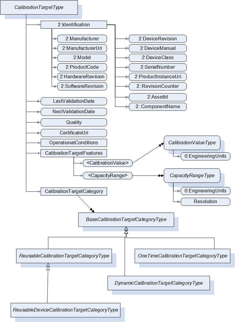
7.3 Calibration Target Information Model overview
The Calibration Target Management Information Model defines the CalibrationTargetType (see Figure 11, and 7.4.1 for details). It represents a calibration target and contains base information about the last validation date of the calibration target, its identification, operational conditions, etc. What the calibration target can be used for is provided in a folder of calibration target features, potentially supporting several features. This specification distinguishes different categories of calibration targets, which is provided by the calibration target category.
The information model only provides the TypeDefinitions to manage calibration targets. It does not provide, how to organize several calibration targets in an OPC UA Server. This is either done in a vendor-specific manner or defined by some other companion specifications.
7.4 OPC UA ObjectTypes
7.4.1 CalibrationTargetType ObjectType
The CalibrationTargetType provides information about a calibration target and is formally defined in Table 48. This concrete ObjectType can directly be used to represent a calibration target, or subtyped to define specific types of calibration targets.
| Attribute | Value | ||||
| BrowseName | CalibrationTargetType | ||||
| IsAbstract | False | ||||
| Description | Provides information about a calibration target. | ||||
| References | Node Class | BrowseName | DataType | TypeDefinition | Other |
|---|---|---|---|---|---|
| Subtype of the 0:BaseObjectType defined in OPC 10000-5, i.e. inheriting the InstanceDeclarations of that Node. | |||||
| 0:HasComponent | Object | 2:Identification | -- | 2:FunctionalGroupType | M |
| 0:HasProperty | Variable | LastValidationDate | 0:UtcTime | 0:PropertyType | O |
| 0:HasProperty | Variable | NextValidationDate | 0:UtcTime | 0:PropertyType | O |
| 0:HasProperty | Variable | Quality | 0:Byte | 0:PropertyType | O |
| 0:HasProperty | Variable | CertificateUri | 0:String | 0:PropertyType | O |
| 0:HasComponent | Object | CalibrationTargetCategory | - | BaseCalibrationTargetCategoryType | M |
| 0:HasComponent | Object | OperationalConditions | - | 0:FolderType | O |
| 0:HasComponent | Object | CalibrationTargetFeatures | - | 0:FolderType | M |
The 2:Identification Object, using the standardized name defined in OPC 10000-100, provides identification information about the calibration target. It implements the 2:IVendorNameplateType and 2:ITagNameplateType, see Table 51. The Properties defined by those interfaces are listed in Table 24. All Properties are defined as optional. It is recommended to provide the 2:ProductInstanceUri to uniquely identify the calibration target. Other Properties, like 2:SoftwareRevision, will in most cases not be provided. If the calibration target is a device (ReusableDeviceCalibrationTargetCategoryType, see 7.4.4), they might be provided.
The optional LastValidationDate provides the date, the calibration target was validated the last time. If there is no specific validation date known, the date when the calibration target was bought or created should be used. If the CalibrationTargetCategory is of type ReusableCalibrationTargetCategoryType or a subtype, the LastValidationDate shall be provided.
The optional NextValidationDate provides the date, when the calibration target should be validated the next time. If this date is not known, the Property should be omitted.
Note: Potentially the NextValidationDate is in the past, when the next validation did not take place.
The optional Quality provides the quality of the calibration target in percentage, this is, the value shall be between 0 and 100. 100 means the highest quality, 0 the lowest. The semantic of the quality is application-specific and not further defined in this specification.
The optional CertificateUri contains the URI of a certificate of the calibration target, in case the calibration target is certified and the information available. Otherwise, the Property should be omitted. The String shall be a URI as defined by RFC 3986.
Note: In many cases, the NextValidationDate, Quality, and CertificateUri will be writable and maintained from outside the Server by updating the values.
The CalibrationTargetCategory defines what category the calibration target is of. The BaseCalibrationTargetCategoryType is defined in 7.4.2. Instances of CalibrationTargetType shall use a subtype of this abstract ObjectType, and thereby provide the category of the calibration target.
The optional OperationalConditions is a folder containing information about operational conditions of the calibration target. For example, it might provide in what ranges of humidity the calibration target can be operated. It might also provide correction information, for example, depending on the temperature the calibration values need to be corrected (in case of a length, the length might increase with high temperatures). This specification just provides this folder as grouping construct for this information. The concrete information is either vendor-specific or needs to be defined by other companion specifications. If no operational conditions are provided, this folder should be omitted.
The mandatory CalibrationTargetFeatures is a folder containing information about the features of a calibration target, that is, what can be calibrated with the calibration target.
It can contain one or more calibration values. A calibration value indicates the value the calibration target provides for calibration and includes its quantity and engineering unit. The VariableType representing calibration values is defined in 7.5.1.
It can contain one or more capacity ranges. A capacity range indicates a range (low and high value) as well as a resolution, and thus defines a number of values the calibration target provides for calibration and includes the quantity and engineering unit. The VariableType representing capacity ranges is defined in 7.5.2.
It can contain other mechanisms to define the features of a calibration target not defined in this specification.
Although all components of CalibrationTargetFeatures are defined as optional, each instance shall have at least one feature.
The components of the CalibrationTargetType have additional subcomponents which are defined in Table 49.
| BrowsePath | References | Node Class | BrowseName | DataType | TypeDefinition | Others |
| CalibrationTargetFeatures | 0:HasComponent | Variable | <CalibrationValue> | 0:Number | CalibrationValueType | OP |
| CalibrationTargetFeatures | 0:HasComponent | Variable | <CapacityRange> | 0:Range | CapacityRangeType | OP |
| Properties of the 2:IVendorNameplateType defined in OPC 10000-100 | ||||||
| 2:Identification | 0:HasProperty | Variable | 2:Manufacturer | 0:LocalizedText | 0:PropertyType | O |
| 2:Identification | 0:HasProperty | Variable | 2:ManufacturerUri | 0:String | 0:PropertyType | O |
| 2:Identification | 0:HasProperty | Variable | 2:Model | 0:LocalizedText | 0:PropertyType | O |
| 2:Identification | 0:HasProperty | Variable | 2:ProductCode | 0:String | 0:PropertyType | O |
| 2:Identification | 0:HasProperty | Variable | 2:HardwareRevision | 0:String | 0:PropertyType | O |
| 2:Identification | 0:HasProperty | Variable | 2:SoftwareRevision | 0:String | 0:PropertyType | O |
| 2:Identification | 0:HasProperty | Variable | 2:DeviceRevision | 0:String | 0:PropertyType | O |
| 2:Identification | 0:HasProperty | Variable | 2:DeviceManual | 0:String | 0:PropertyType | O |
| 2:Identification | 0:HasProperty | Variable | 2:DeviceClass | 0:String | 0:PropertyType | O |
| 2:Identification | 0:HasProperty | Variable | 2:SerialNumber | 0:String | 0:PropertyType | O |
| 2:Identification | 0:HasProperty | Variable | 2:ProductInstanceUri | 0:String | 0:PropertyType | O |
| 2:Identification | 0:HasProperty | Variable | 2:RevisionCounter | 0:Int32 | 0:PropertyType | O |
| Properties of the 2:ITagNameplateType defined in OPC 10000-100 | ||||||
| 2:Identification | 0:HasProperty | Variable | 2:AssetId | 0:String | 0:PropertyType | O |
| 2:Identification | 0:HasProperty | Variable | 2:ComponentName | 0:LocalizedText | 0:PropertyType | O |
The child Nodes of the CalibrationTargetType have additional Attribute values defined in Table 50.
| BrowsePath | Description Attribute | ||
| 2:Identification | Provides identification information. | ||
| LastValidationDate | Provides the date, the calibration target was validated the last time. If there is no specific validation date known, the date when the calibration target was bought or created should be used. | ||
| NextValidationDate | Provides the date, when the calibration target should be validated the next time. If this date is not known, the Property should be omitted. Note: Potentially the NextValidationDate is in the past, when the next validation did not take place. | ||
| Quality | Provides the quality of the calibration target in percentage, this is, the value shall be between 0 and 100. 100 means the highest quality, 0 the lowest. The semantic of the quality is application-specific. | ||
| CertificateUri | Contains the Uri of a certificate of the calibration target, in case the calibration target is certified and the information available. Otherwise, the Property should be omitted. | ||
| CalibrationTargetCategory | Defines what category the calibration target is of. | ||
| OperationalConditions | A folder containing information about operational conditions of the calibration target. For example, it might provide in what ranges of humidity the calibration target can be operated. It might also provide correction information, for example, depending on the temperature the calibration values need to be corrected (in case of a length, the length might increase with high temperatures). If no operational conditions are provided, this folder should be omitted. | ||
| CalibrationTargetFeatures | A folder containing information about the features of a calibration target, that is, what can be calibrated with the calibration target. | ||
| A calibration value indicates the value the calibration target provides for calibration and includes its quantity and engineering unit. | ||
| A capacity range indicates a range (low and high value) as well as a resolution, and thus defines a number of values the calibration target provides for calibration and includes the quantity and engineering unit. |
The components of the CalibrationTargetType have additional references which are defined in Table 51.
| SourceBrowsePath | Reference Type | Is Forward | TargetBrowsePath |
| 2:Identification | 0:HasInterface | True | 2:IVendorNameplateType |
| 2:Identification | 0:HasInterface | True | 2:ITagNameplateType |
7.4.2 BaseCalibrationTargetCategoryType ObjectType
The BaseCalibrationTargetCategoryType is an abstract ObjectType used for categorizing calibration targets and is formally defined in Table 52.
| Attribute | Value | ||||
| BrowseName | BaseCalibrationTargetCategoryType | ||||
| IsAbstract | True | ||||
| Description | Abstract base type for categorizing calibration targets. Subtypes define the concrete categories. | ||||
| References | Node Class | BrowseName | DataType | TypeDefinition | Other |
|---|---|---|---|---|---|
| Subtype of the 0:BaseObjectType defined in OPC 10000-5, i.e. inheriting the InstanceDeclarations of that Node. | |||||
7.4.3 ReusableCalibrationTargetCategoryType ObjectType
The ReusableCalibrationTargetCategoryType categorizes a calibration target to be reused several times. For example, a calibration target like a meter, that is bought specifically for calibration and not destroyed by an individual usage is of this category. The ObjectType is formally defined in Table 53.
| Attribute | Value | ||||
| BrowseName | ReusableCalibrationTargetCategoryType | ||||
| IsAbstract | False | ||||
| Description | Categorizes a calibration target to be reused several times. For example, a calibration target like a meter, that is bought specifically for calibration and not destroyed by an individual usage is of this category. | ||||
| References | Node Class | BrowseName | DataType | TypeDefinition | Other |
|---|---|---|---|---|---|
| Subtype of the BaseCalibrationTargetCategoryType defined in 7.4.2, i.e. inheriting the InstanceDeclarations of that Node. | |||||
7.4.4 ReusableDeviceCalibrationTargetCategoryType ObjectType
The ReusableDeviceCalibrationTargetCategoryType is a subtype of the ReusableCalibrationTargetCategoryType and categorizes a calibration target to be a reusable device that produces a certain environment like pressure that can be used for calibration. The ObjectType is formally defined in Table 54.
| Attribute | Value | ||||
| BrowseName | ReusableDeviceCalibrationTargetCategoryType | ||||
| IsAbstract | False | ||||
| Description | Categorizes a calibration target to be a reusable device that produces a certain environment like pressure that can be used for calibration. | ||||
| References | Node Class | BrowseName | DataType | TypeDefinition | Other |
|---|---|---|---|---|---|
| Subtype of the ReusableCalibrationTargetCategoryType defined in 7.4.3, i.e. inheriting the InstanceDeclarations of that Node. | |||||
This ObjectType does not define any InstanceDeclarations.
7.4.5 OneTimeCalibrationTargetCategoryType ObjectType
The OneTimeCalibrationTargetCategoryType categorizes a calibration target to be used only once, for example because the calibration destroys the target. Typically, Objects of this ObjectType do not represent one individual calibration target, but a batch of calibration targets with the same characteristics. In that case, the information provided by the CalibrationTargetType, like 2:Identification, represents the batch of calibration targets. The ObjectType is formally defined in Table 55.
| Attribute | Value | ||||
| BrowseName | OneTimeCalibrationTargetCategoryType | ||||
| IsAbstract | False | ||||
| Description | Categorizes a calibration target to be used only once, for example because the calibration destroys the target. Typically, Objects of this ObjectType do not represent one individual calibration target, but a batch of calibration targets with the same characteristics. | ||||
| References | Node Class | BrowseName | DataType | TypeDefinition | Other |
|---|---|---|---|---|---|
| Subtype of the BaseCalibrationTargetCategoryType defined in 7.4.2, i.e. inheriting the InstanceDeclarations of that Node. | |||||
This ObjectType does not define any InstanceDeclarations.
7.4.6 DynamicCalibrationTargetCategoryType ObjectType
The DynamicCalibrationTargetCategoryType characterizes a calibration target that is created by using a high precision measurement instrument, to determine the measures of an item to use it later on to calibrate lower precision equipment with it. This Item can be a piece created during the normal production process or an item specifically created for calibration purposes. Such targets are usually short lived as they are not made from special wear resistant materials, which distinguishes them from the ReusableCalibrationTargetCategoryType. The calibration target represents an individual piece or item, that is, if a new piece should be used or item is created, a new Object of this ObjectType shall be created. The ObjectType is formally defined in Table 56.
| Attribute | Value | ||||
| BrowseName | DynamicCalibrationTargetCategoryType | ||||
| IsAbstract | False | ||||
| Description | Characterizes a calibration target to be used together with a measurement instrument, that determines the values to be calibrated. It can be a piece created during the normal production process or an item specifically created for calibration purposes. The calibration target represents an individual piece or item, that is, if a new piece should be used or item is created, a new Object of this ObjectType is created. | ||||
| References | Node Class | BrowseName | DataType | TypeDefinition | Other |
|---|---|---|---|---|---|
| Subtype of the BaseCalibrationTargetCategoryType defined in 7.4.2, i.e. inheriting the InstanceDeclarations of that Node. | |||||
This ObjectType does not define any InstanceDeclarations.
Objects of this ObjectType should use References of the ReferenceType HasReferenceMeasurementInstrument defined in 7.6.1, or a subtype of it, to relate the calibration target to the measurement instrument used to determine its features.
In case the piece or item used as calibration target is also managed otherwise by the OPC UA Server, Objects of this ObjectType may reference the other representation to make the relationship explicit.
7.5 OPC UA VariableType
7.5.1 CalibrationValueType
The CalibrationValueType is a subtype of the DataItemType. It represents the specific quantity and value (with engineering unit) that a calibration target provides for calibration of equipment. The VariableType is formally defined in Table 57.
| Attribute | Value | |||||
| BrowseName | CalibrationValueType | |||||
| IsAbstract | False | |||||
| ValueRank | -2 (-2 = Any) | |||||
| DataType | 0:Number | |||||
| Description | Represents the specific quantity and value (with engineering unit) that a calibration target provides for calibration of equipment. | |||||
| References | NodeClass | BrowseName | DataType | TypeDefinition | Other | |
|---|---|---|---|---|---|---|
| Subtype of the 0:DataItemType defined in OPC 10000-8, i.e. inheriting the InstanceDeclarations of that Node | ||||||
| 0:HasProperty | Variable | 0:EngineeringUnits | 0:EUInformation | 0:PropertyType | M | |
The CalibrationValueType inherits the Properties of the DataItemType. That does include the optional 0:ValuePrecision, defining the precision of the calibration value.
The mandatory 0:EngineeringUnits defines the engineering unit of the calibration values.
Remark: The quantity of the calibration value is of importance. This specification waits for this to be solved in the base OPC UA specification (OPC 10000-8), and will use this afterwards.
The VariableType can be used with an (multi-dimensional) array or scalar values. When a calibration target provides several independent values, e.g., lengths, that can be used for calibration, each one should get its own instance of CalibrationValueType. If the calibration target provides for example a scale for length, the CapacityRangeType should be used. The array of the CalibrationValueType shall only be used, when it represents one overall value consisting of a number of distinct values for example the spatial frequency of line pattern blocks on a resolution test chart for calibration of optical instruments.
7.5.2 CapacityRangeType
The CapacityRangeType is a subtype of the DataItemType. It is used to represent a scale of calibration values. The value of the Variable defines the range (lowest and highest value), and the resolution the size of each step. The VariableType is formally defined in Table 57.
| Attribute | Value | |||||
| BrowseName | CapacityRangeType | |||||
| IsAbstract | False | |||||
| ValueRank | -1 (-1 = Scalar) | |||||
| DataType | 0:Range | |||||
| Description | Represent a scale of calibration values. The value defines the range (lowest and highest value), and the resolution property the size of each step. | |||||
| References | NodeClass | BrowseName | DataType | TypeDefinition | Other | |
|---|---|---|---|---|---|---|
| Subtype of the 0:DataItemType defined in OPC 10000-8, i.e. inheriting the InstanceDeclarations of that Node | ||||||
| 0:HasProperty | Variable | 0:EngineeringUnits | 0:EUInformation | 0:PropertyType | M | |
| 0:HasProperty | Variable | Resolution | 0:Double | 0:PropertyType | M | |
The CapacityRangeType inherits the Properties of the DataItemType. That does include the optional 0:ValuePrecision, defining the precision of the calibration value.
The mandatory 0:EngineeringUnits defines the engineering unit of the calibration values.
The Resolution defines the step size and is used in combination with the Range provided in the Value Attribute to determine, what individual calibration values can be used for calibration.
Remark: The quantity of the calibration value is of importance. This specification waits for this to be solved in the base OPC UA specification (OPC 10000-8), and will use this afterwards.
7.6 OPC UA ReferenceTypes
7.6.1 HasReferenceMeasurementInstrument
The HasReferenceMeasurementInstrument is a concrete ReferenceType and can be used directly. It is a subtype of NonHierarchicalReferences.
The semantic of this ReferenceType is to link a Node using a reference measurement instrument to such an instrument, like for example a calibration target using a reference measurement instrument.
The SourceNode of References of this type can be any Node using a reference measurement instrument, like for example instances of DynamicCalibrationTargetCategoryType.
The TargetNode of this ReferenceType can be any Node representing a measurement instrument.
The HasReferenceMeasurementInstrument is formally defined in Table 47.
| Attributes | Value | ||
| BrowseName | HasReferenceMeasurementInstrument | ||
| InverseName | ReferenceMeasurementInstrumentOf | ||
| Symmetric | False | ||
| IsAbstract | False | ||
| Description | Relates the source node to a reference measurement instrument, like for example a calibration target using a reference measurement instrument. | ||
| References | NodeClass | BrowseName | Comment |
|---|---|---|---|
| Subtype of NonHierarchicalReferences defined in OPC 10000-5 | |||
8 Profiles and ConformanceUnits
8.1 Conformance Units
This chapter defines the corresponding Conformance Units for the OPC UA Information Model for Industrial Automation (see Table 60).
| Category | Title | Description |
| Server | IA Stacklight | Supports the base functionality defined in the BasicStacklightType. |
| Server | IA Statistical Data | Supports the base functionality defined in the IStatisticsType. |
| Server | IA CT Base Elements | Supports the CalibrationTargetType and referenced TypeDefinitions in the AddressSpace and at least one instance of CalibrationTargetType or a subtype having the mandatory Identification and CalibrationTargetFeatures subcomponents. |
| Server | IA CT Reusable Calibration Target | Supports the ReusableCalibrationTargetCategoryType in the AddressSpace and at least one instance of CalibrationTargetType or a subtype having an instance of ReusableCalibrationTargetCategoryType or a subtype as CalibrationTargetCategory. |
| Server | IA CT Reusable Device Calibration Target | Supports the ReusableDeviceCalibrationTargetCategoryType in the AddressSpace and at least one instance of CalibrationTargetType or a subtype having an instance of ReusableDeviceCalibrationTargetCategoryType or a subtype as CalibrationTargetCategory. |
| Server | IA CT One-Time Calibration Target | Supports the OneTimeCalibrationTargetCategoryType in the AddressSpace and at least one instance of CalibrationTargetType or a subtype having an instance of OneTimeCalibrationTargetCategoryType or a subtype as CalibrationTargetCategory. |
| Server | IA CT Dynamic Calibration Target | Supports the DynamicCalibrationTargetCategoryType in the AddressSpace and at least one instance of CalibrationTargetType or a subtype having an instance of DynamicCalibrationTargetCategoryType or a subtype as CalibrationTargetCategory. |
| Server | IA CT Manufactured Target | Supports at least one instance of CalibrationTargetType or a subtype having OperationalConditions Object and optionally vendor-specific subcomponents and the Identification Object and at least the Manufacturer, Model, and SerialNumber Properties and optionally the other Properties defined for the Identification Object. |
| Server | IA CT Quality Controlled Target | Supports at least one instance of CalibrationTargetType or a subtype providing the Quality Property. |
| Server | IA CT Validated Target | Supports at least one instance of CalibrationTargetType or a subtype providing the LastValidationDate Property and optionally the NextValidationDate and CertificateUri Properties. |
| Server | IA CT Distinct Quantity Value Target | Supports at least one instance of CalibrationTargetType or a subtype having at least one instance of CalibrationValueType or a subtype in its CalibrationTargetFeatures. The instance of CalibrationValueType or a subtype shall have all mandatory Properties and optionally the optional Properties. |
| Server | IA CT Quantity Range Target | Supports at least one instance of CalibrationTargetType or a subtype having at least one instance of CapacityRangeType or a subtype in its CalibrationTargetFeatures. The instance of CapacityRangeType or a subtype shall have all mandatory Properties and optionally the optional Properties. |
| Server | IA CT Custom Featured Target | Supports at least one instance of CalibrationTargetType or a subtype having at least one component in its CalibrationTargetFeatures which is not of TypeDefinition CalibrationValueType or CapacityRangeType or one of their subtypes. |
| Client | IA CT Client Base | The client can make use of the instances of CalibrationTargetType and its subtypes and can make use of the Manufacturer, Model and SerialNumber and optionally the other Properties of the Identification Object. |
| Client | IA CT Client CalibrationTargetCategory | The client can make use of the CalibrationTargetCategory Object of instances of CalibrationTargetType and can distinguish the subtypes defined for the BaseCalibrationTargetCategoryType. |
| Client | IA CT Client CalibrationTargetFeatures | The client can make use of all components provided in the CalibrationTargetFeatures Object of instances of CalibrationTargetType. If the component is of type CalibrationValueType or CapacityRangeType, the client shall be capable to interpret the DataTypes and all mandatory and option Properties. If the component is of another type, the client shall at least at least notice the component and use its base features like DisplayName. |
| Client | IA CT Client Quality Monitoring | The client can make use of the Properties LastValidationDate, NextValidationDate, Quality, and CertificateUri provided by instances of CalibrationTargetType or a subtype. |
8.2 Profiles
8.2.1 Profile list
Table 61 lists all Profiles defined in this document and defines their URIs.
| Profile | URI |
| IA Stacklight Server Profile | http://opcfoundation.org/UA-Profile/IA/Server/Stacklight |
| IA Statistical Data Server Profile | http://opcfoundation.org/UA-Profile/IA/Server/StatisticalData |
| IA CT Reusable Calibration Target Handling Server Facet | http://opcfoundation.org/UA-Profile/IA/Server/CalibrationTargetReusable |
| IA CT Reusable Device Calibration Target Handling Server Facet | http://opcfoundation.org/UA-Profile/IA/Server/CalibrationTargetReusableDevice |
| IA CT One-Time Calibration Target Handling Server Facet | http://opcfoundation.org/UA-Profile/IA/Server/CalibrationTargetOneTime |
| IA CT Dynamic Calibration Target Handling Server Facet | http://opcfoundation.org/UA-Profile/IA/Server/CalibrationTargetDynamic |
| IA CT Full Calibration Target Handling Server Facet | http://opcfoundation.org/UA-Profile/IA/Server/CalibrationTargetFull |
| IA CT Calibration Target Quality Monitoring Client | http://opcfoundation.org/UA-Profile/IA/Client/CalibrationTargetQualityMonitoring |
| IA CT Calibration Target Handling Client | http://opcfoundation.org/UA-Profile/IA/Client/CalibrationTargetHandling |
8.2.2 Server Facets
8.2.2.1 Overview
The following sections specify the Facets available for Servers that implement the Industrial Automation companion specification. Each section defines and describes a Facet or Profile.
8.2.2.2 IA Stacklight Server Profile
Table 62 defines a Profile that describes the capability of a Server to provide stacklight information.
| Group | Conformance Unit / Profile Title | Mandatory / Optional |
| IA | IA Stacklight | M |
8.2.2.3 IA Statistical Data Server Profile
Table 63 defines a Profile that describes the capability of a Server to provide statistical data.
| Group | Conformance Unit / Profile Title | Mandatory / Optional |
| IA | IA Statistical Data | M |
8.2.2.4 IA CT Reusable Calibration Target Handling Server Facet
This Facet describes that a Server supports calibration targets of category reusable calibration targets. All instances of CalibrationTargetType or a subtype in the Server having the CalibrationTargetCategory of type ReusableCalibrationTargetCategoryType or a subtype shall support the requirements as defined in the mandatory Conformance Units, and optionally the optional Conformance Units. Each of those instances shall support at least one of the following optional Conformance Units IA CT Distinct Quantity Value Target, IA CT Quantity Range Target or IA CT Custom Featured Target.
Table 62 defines Conformance Units of the Facet.
| Group | Conformance Unit / Profile Title | Mandatory / Optional |
| IA | IA CT Base Elements | M |
| IA | IA CT Reusable Calibration Target | M |
| IA | IA CT Manufactured Target | M |
| IA | IA CT Quality Controlled Target | O |
| IA | IA CT Validated Target | M |
| IA | IA CT Distinct Quantity Value Target | O |
| IA | IA CT Quantity Range Target | O |
| IA | IA CT Custom Featured Target | O |
8.2.2.5 IA CT Reusable Device Calibration Target Handling Server Facet
This Facet describes that a Server supports calibration targets of category reusable calibration targets. All instances of CalibrationTargetType or a subtype in the Server having the CalibrationTargetCategory of type ReusableDeviceCalibrationTargetCategoryType or a subtype shall support the requirements as defined in the mandatory Conformance Units, and optionally the optional Conformance Units. Each of those instances shall support at least one of the following optional Conformance Units IA CT Distinct Quantity Value Target, IA CT Quantity Range Target or IA CT Custom Featured Target.
Table 65 defines Conformance Units of the Facet.
| Group | Conformance Unit / Profile Title | Mandatory / Optional |
| IA | IA CT Base Elements | M |
| IA | IA CT Reusable Device Calibration Target | M |
| IA | IA CT Manufactured Target | M |
| IA | IA CT Quality Controlled Target | O |
| IA | IA CT Validated Target | M |
| IA | IA CT Distinct Quantity Value Target | O |
| IA | IA CT Quantity Range Target | O |
| IA | IA CT Custom Featured Target | O |
8.2.2.6 IA CT One-Time Calibration Target Handling Server Facet
This Facet describes that a Server supports calibration targets of category reusable calibration targets. All instances of CalibrationTargetType or a subtype in the Server having the CalibrationTargetCategory of type OneTimeCalibrationTargetCategoryType or a subtype shall support the requirements as defined in the mandatory Conformance Units, and optionally the optional Conformance Units. Each of those instances shall support at least one of the following optional Conformance Units IA CT Distinct Quantity Value Target, IA CT Quantity Range Target or IA CT Custom Featured Target.
Table 66 defines Conformance Units of the Facet.
| Group | Conformance Unit / Profile Title | Mandatory / Optional |
| IA | IA CT Base Elements | M |
| IA | IA CT One-Time Calibration Target | M |
| IA | IA CT Manufactured Target | O |
| IA | IA CT Validated Target | O |
| IA | IA CT Distinct Quantity Value Target | O |
| IA | IA CT Quantity Range Target | O |
| IA | IA CT Custom Featured Target | O |
8.2.2.7 IA CT Dynamic Calibration Target Handling Server Facet
This Facet describes that a Server supports calibration targets of category reusable calibration targets. All instances of CalibrationTargetType or a subtype in the Server having the CalibrationTargetCategory of type DynamicCalibrationTargetCategoryType or a subtype shall support the requirements as defined in the mandatory Conformance Units, and optionally the optional Conformance Units. Each of those instances shall support at least one of the following optional Conformance Units IA CT Distinct Quantity Value Target, IA CT Quantity Range Target or IA CT Custom Featured Target.
Table 62 defines Conformance Units of the Facet.
| Group | Conformance Unit / Profile Title | Mandatory / Optional |
| IA | IA CT Base Elements | M |
| IA | IA CT Dynamic Calibration Target | M |
| IA | IA CT Manufactured Target | O |
| IA | IA CT Distinct Quantity Value Target | O |
| IA | IA CT Quantity Range Target | O |
| IA | IA CT Custom Featured Target | O |
8.2.2.8 IA CT Full Calibration Target Handling Server Facet
This Facet describes that a Server supports calibration targets of the categories: reusable calibration targets, reusable device calibration targets, one-time calibration targets and dynamic calibration targets.
Table 62 defines contained Facets of the Facet.
| Group | Conformance Unit / Profile Title | Mandatory / Optional |
| Profile | IA CT Reusable Calibration Target Handling Server Facet | |
| Profile | IA CT Reusable Device Calibration Target Handling Server Facet | |
| Profile | IA CT One-Time Calibration Target Handling Server Facet | |
| Profile | IA CT Dynamic Calibration Target Handling Server Facet |
8.2.3 Client Facets
8.2.3.1 Overview
The following sections specify the Facets available for Clients that implement the Industrial Automation companion specification. Each section defines and describes a Facet or Profile.
8.2.3.2 IA CT Calibration Target Quality Monitoring Client Facet
This Facet describes that a Client can make use of the base information of calibration targets to monitor the quality and validation dates of the calibration targets.
Table 69 defines Conformance Units of the Facet.
| Group | Conformance Unit / Profile Title | Mandatory / Optional |
| IA | IA CT Client Base | M |
| IA | IA CT Client Quality Monitoring | M |
8.2.3.3 IA CT Calibration Target Handling Client Facet
This Facet describes that a Client can make use of the base information of calibration targets and handle the calibration targets by using the information about the category and the features, and optionally the quality information.
Table 69 defines Conformance Units of the Facet.
| Group | Conformance Unit / Profile Title | Mandatory / Optional |
| IA | IA CT Client Base | M |
| IA | IA CT Client CalibrationTargetCategory | M |
| IA | IA CT Client CalibrationTargetFeatures | M |
| IA | IA CT Client Quality Monitoring | O |
9 Namespaces
9.1 Namespace Metadata
Table 71 defines the namespace metadata for this document. The Object is used to provide version information for the namespace and an indication about static Nodes. Static Nodes are identical for all Attributes in all Servers, including the Value Attribute. See OPC 10000-5 for more details.
The information is provided as Object of type NamespaceMetadataType. This Object is a component of the Namespaces Object that is part of the Server Object. The NamespaceMetadataType ObjectType and its Properties are defined in OPC 10000-5.
The version information is also provided as part of the ModelTableEntry in the UANodeSet XML file. The UANodeSet XML schema is defined in OPC 10000-6.
| Attribute | Value | ||
| BrowseName | http://opcfoundation.org/UA/IA/ | ||
| Property | DataType | Value | |
|---|---|---|---|
| NamespaceUri | String | http://opcfoundation.org/UA/IA/ | |
| NamespaceVersion | String | 1.01.4 | |
| NamespacePublicationDate | DateTime | 2025-05-23 | |
| IsNamespaceSubset | Boolean | False | |
| StaticNodeIdTypes | IdType [] | 0 | |
| StaticNumericNodeIdRange | NumericRange [] | ||
| StaticStringNodeIdPattern | String | ||
Note: The IsNamespaceSubset Property is set to False as the UANodeSet XML file contains the complete Namespace. Servers only exposing a subset of the Namespace need to change the value to True.
9.2 Handling of OPC UA Namespaces
Namespaces are used by OPC UA to create unique identifiers across different naming authorities. The Attributes NodeId and BrowseName are identifiers. A Node in the UA AddressSpace is unambiguously identified using a NodeId. Unlike NodeIds, the BrowseName cannot be used to unambiguously identify a Node. Different Nodes may have the same BrowseName. They are used to build a browse path between two Nodes or to define a standard Property.
Servers may often choose to use the same namespace for the NodeId and the BrowseName. However, if they want to provide a standard Property, its BrowseName shall have the namespace of the standards body although the namespace of the NodeId reflects something else, for example the EngineeringUnits Property. All NodeIds of Nodes not defined in this document shall not use the standard namespaces.
Table 72 provides a list of mandatory and optional namespaces used in an Industrial Automation OPC UA Server.
| NamespaceURI | Description | Use |
| http://opcfoundation.org/UA/ | Namespace for NodeIds and BrowseNames defined in the OPC UA specification. This namespace shall have namespace index 0. | Mandatory |
| Local Server URI | Namespace for nodes defined in the local server. This namespace shall have namespace index 1. | Mandatory |
| http://opcfoundation.org/UA/DI/ | Namespace for NodeIds and BrowseNames defined in OPC 10000-100. The namespace index is Server specific. | Mandatory |
| http://opcfoundation.org/UA/IA/ | Namespace for NodeIds and BrowseNames defined in this document. The namespace index is Server specific. | Mandatory |
| Vendor specific types | A Server may provide vendor-specific types like types derived from ObjectTypes defined in this document in a vendor-specific namespace. | Optional |
| Vendor specific instances | A Server provides vendor-specific instances of the standard types or vendor-specific instances of vendor-specific types in a vendor-specific namespace. It is recommended to separate vendor specific types and vendor specific instances into two or more namespaces. | Mandatory |
Table 73 provides a list of namespaces and their index used for BrowseNames in this document. The default namespace of this document is not listed since all BrowseNames without prefix use this default namespace.
| NamespaceURI | Namespace Index | Example |
| http://opcfoundation.org/UA/ | 0 | 0:EngineeringUnits |
| http://opcfoundation.org/UA/DI/ | 2 | 2:DeviceRevision |
Annex A Industrial Automation Namespace and mappings (Normative)
A.1 NodeSet and Supplementary Files for Industrial Automation (IA) Information Model
The IA Information Model is identified by the following URI:
http://opcfoundation.org/UA/IA/
Documentation for the NamespaceUri can be found here.
The NodeSet associated with this version of specification can be found here:
https://reference.opcfoundation.org/nodesets/?u=http://opcfoundation.org/UA/IA/&v=1.01.4&i=1
The NodeSet associated with the latest version of the specification can be found here:
https://reference.opcfoundation.org/nodesets/?u=http://opcfoundation.org/UA/IA/&i=1
The supplementary files associated with this version of specification can be found here:
https://reference.opcfoundation.org/nodesets/?u=http://opcfoundation.org/UA/IA/&v=1.01.4&i=2
The supplementary files associated with the latest version of the specification can be found here:
https://reference.opcfoundation.org/nodesets/?u=http://opcfoundation.org/UA/IA/&i=2
_____________
Agreement of Use
COPYRIGHT RESTRICTIONS
Any unauthorized use of this specification may violate copyright laws, trademark laws, and communications regulations and statutes. This document contains information which is protected by copyright. All Rights Reserved. No part of this work covered by copyright herein may be reproduced or used in any form or by any means--graphic, electronic, or mechanical, including photocopying, recording, taping, or information storage and retrieval systems--without permission of the copyright owner.
OPC Foundation members and non-members are prohibited from copying and redistributing this specification. All copies must be obtained on an individual basis, directly from the OPC Foundation Web site
http://www.opcfoundation.org.
PATENTS
The attention of adopters is directed to the possibility that compliance with or adoption of OPC specifications may require use of an invention covered by patent rights. OPC shall not be responsible for identifying patents for which a license may be required by any OPC specification, or for conducting legal inquiries into the legal validity or scope of those patents that are brought to its attention. OPC specifications are prospective and advisory only. Prospective users are responsible for protecting themselves against liability for infringement of patents.
WARRANTY AND LIABILITY DISCLAIMERS
WHILE THIS PUBLICATION IS BELIEVED TO BE ACCURATE, IT IS PROVIDED "AS IS" AND MAY CONTAIN ERRORS OR MISPRINTS. THE OPC FOUDATION MAKES NO WARRANTY OF ANY KIND, EXPRESSED OR IMPLIED, WITH REGARD TO THIS PUBLICATION, INCLUDING BUT NOT LIMITED TO ANY WARRANTY OF TITLE OR OWNERSHIP, IMPLIED WARRANTY OF MERCHANTABILITY OR WARRANTY OF FITNESS FOR A PARTICULAR PURPOSE OR USE. IN NO EVENT SHALL THE OPC FOUNDATION BE LIABLE FOR ERRORS CONTAINED HEREIN OR FOR DIRECT, INDIRECT, INCIDENTAL, SPECIAL, CONSEQUENTIAL, RELIANCE OR COVER DAMAGES, INCLUDING LOSS OF PROFITS, REVENUE, DATA OR USE, INCURRED BY ANY USER OR ANY THIRD PARTY IN CONNECTION WITH THE FURNISHING, PERFORMANCE, OR USE OF THIS MATERIAL, EVEN IF ADVISED OF THE POSSIBILITY OF SUCH DAMAGES.
The entire risk as to the quality and performance of software developed using this specification is borne by you.
RESTRICTED RIGHTS LEGEND
This Specification is provided with Restricted Rights. Use, duplication or disclosure by the U.S. government is subject to restrictions as set forth in (a) this Agreement pursuant to DFARs 227.7202-3(a); (b) subparagraph (c)(1)(i) of the Rights in Technical Data and Computer Software clause at DFARs 252.227-7013; or (c) the Commercial Computer Software Restricted Rights clause at FAR 52.227-19 subdivision (c)(1) and (2), as applicable. Contractor / manufacturer are the OPC Foundation, 16101 N. 82nd Street, Suite 3B, Scottsdale, AZ, 85260-1830.
COMPLIANCE
The OPC Foundation shall at all times be the sole entity that may authorize developers, suppliers and sellers of hardware and software to use certification marks, trademarks or other special designations to indicate compliance with these materials. Products developed using this specification may claim compliance or conformance with this specification if and only if the software satisfactorily meets the certification requirements set by the OPC Foundation. Products that do not meet these requirements may claim only that the product was based on this specification and must not claim compliance or conformance with this specification.
Trademarks
Most computer and software brand names have trademarks or registered trademarks. The individual trademarks have not been listed here.
GENERAL PROVISIONS
Should any provision of this Agreement be held to be void, invalid, unenforceable or illegal by a court, the validity and enforceability of the other provisions shall not be affected thereby.
This Agreement shall be governed by and construed under the laws of the State of Minnesota, excluding its choice or law rules.
This Agreement embodies the entire understanding between the parties with respect to, and supersedes any prior understanding or agreement (oral or written) relating to, this specification.
ISSUE REPORTING
If an error or problem is found in this specification, the UaNodeSet, or any associated supplementary files, it should be reported as an issue.
The reporting process can be found here: https://opcfoundation.org/resources/issue-tracking/
The Link to the issue tracking project for this document is here:
https://mantis.opcfoundation.org/set_project.php?project_id=129&make_default=no
Revision 1.01.4 Highlights
The following table includes new features and the Mantis issues resolved with this revision.