
1 Scope
This document defines a Companion Specification for Wireless Machine Tool Peripherals (WMTP) using OPC UA constructs to exchange process parameters wireless between components and software systems, such as MES-Systems, mobile devices, etc.
The process parameters are recorded by sensors on the components and are used for process monitoring.
The aim of the specification is to define all relevant process parameters for the use of wireless machine tool peripherals in alignment to the Bluetooth Industial Measurement Devices standard for WMTP (see 2). Only the industry-specific (manufacturer-independent) process values are defined - company-specific process values are not taken into account in the specification.
The first version of the OPC UA Companion Specification for WMTP applies to driven tool units, static tool holders and angle heads. Other sensor-equipped machine peripherals can be modelled on the basis of this Companion Specification, but will probably have to be extended by certain parameters.
2 Normative references
The following documents are referred to in the text in such a way that some or all of their content constitutes requirements of this document. For dated references, only the edition cited applies. For undated references, the latest edition of the referenced document (including any amendments and errata) applies
OPC 10000-1, OPC Unified Architecture - Part 1: Overview and Concepts
http://www.opcfoundation.org/documents/10000-1/
OPC 10000-2, OPC Unified Architecture - Part 2: Security Model
http://www.opcfoundation.org/documents/10000-2/
OPC 10000-3, OPC Unified Architecture - Part 3: Address Space Model
http://www.opcfoundation.org/documents/10000-3/
OPC 10000-4, OPC Unified Architecture - Part 4: Services
http://www.opcfoundation.org/documents/10000-4/
OPC 10000-5, OPC Unified Architecture - Part 5: Information Model
http://www.opcfoundation.org/documents/10000-5/
OPC 10000-6, OPC Unified Architecture - Part 6: Mappings
http://www.opcfoundation.org/documents/10000-6/
OPC 10000-7, OPC Unified Architecture - Part 7: Profiles
http://www.opcfoundation.org/documents/10000-7/
OPC 10000-100, OPC Unified Architecture - Part 100: Devices
http://www.opcfoundation.org/documents/10000-100/
OPC 40001-1, OPC UA for Machinery - Part 1: Basic Building Blocks
http://www.opcfoundation.org/documents/40001-1/
OPC 30081, OPC UA for Process Automation Devices - PA-DIM
http://www.opcfoundation.org/documents/30081/
OPC 40001-2, OPC UA for Machinery - Part2: Process Values
http://www.opcfoundation.org/documents/40001-2/
Bluetooth Industial Measurement Devices for WMTP
https://www.bluetooth.com/specifications/specs/industrial-measurement-device-service-2/
3 Terms, definitions and conventions
3.1 Overview
It is assumed that basic concepts of OPC UA information modelling are understood in this specification. This specification will use these concepts to describe the Wireless Machine Tool Peripheral Information Model. For the purposes of this document, the terms and definitions given in OPC 10000-1, OPC 10000-3, OPC 10000-4, OPC 10000-5, OPC 10000-7, OPC 10000-100, … as well as the following apply.
3.2 OPC UA for Wireless Machine Tool Peripherals terms
3.2.1 Wireless Machine Tool Peripheral
Nonstationary component of a machine tool that can transmit data wirelessly.
3.2.2 Driven Tool Unit
Tool unit with one or more spindles for clamping rotating cutting tools driven by a machine tool.
3.2.3 Static Tool Holder
Tool holder for clamping of non-rotating tools in lathes.
3.2.4 Adjustable Boring Unit
Adjustable boring unit for making holes with different diameters in workpieces.
3.2.5 Workpiece Clamping Device
Device for fixing and positioning workpieces in machine tools.
3.2.6 Touch Probe
A switch that switches when a workpiece surface is touched, providing repeatable geometric data.
3.2.7 Bluetooth
A standard communication protocol for wireless data transmission between devices over a short distance.
3.2.8 3.2.7
Work Cycle
A work cycle is the process enclosing a single operation (e.g., drilling one hole into a workpiece).
3.2.9 3.2.7
Service Cycle
A service cycle is the interval between two maintenance operations. The Service Cycle Data provides values describing the service cycle of the device.
3.3 Abbreviated terms
| AC | Alarm and Condition |
| DCS | Distributed Control Systems |
| ERP | Enterprise Resource Planning |
| HMI | Human Machine Interface |
| HTTP | Hypertext Transfer Protocol |
| IP | Internet Protocol |
| MES | Manufacturing Execution System |
| PLC | Programmable Logical Controller |
| PMS | Production Management System |
| TCP | Transmission Control Protocol |
| UML | Unified Modelling Language |
| URI | Uniform Resource Identifier |
| XML | Extensible Markup Language |
| WMTP | Wireless Machine Tool Peripheral |
3.4 Conventions used in this document
3.4.1 Conventions for Node descriptions
3.4.1.1 Node definitions
Node definitions are specified using tables (see Table 2).
Attributes are defined by providing the Attribute name and a value, or a description of the value.
References are defined by providing the ReferenceType name, the BrowseName of the TargetNode and its NodeClass.
If the TargetNode is a component of the Node being defined in the table the Attributes of the composed Node are defined in the same row of the table.
The DataType is only specified for Variables; "[<number>]" indicates a single-dimensional array, for multi-dimensional arrays the expression is repeated for each dimension (e.g. [2][3] for a two-dimensional array). For all arrays the ArrayDimensions is set as identified by <number> values. If no <number> is set, the corresponding dimension is set to 0, indicating an unknown size. If no number is provided at all the ArrayDimensions can be omitted. If no brackets are provided, it identifies a scalar DataType and the ValueRank is set to the corresponding value (see OPC 10000-3). In addition, ArrayDimensions is set to null or is omitted. If it can be Any or ScalarOrOneDimension, the value is put into "{<value>}", so either "{Any}" or "{ScalarOrOneDimension}" and the ValueRank is set to the corresponding value (see OPC 10000-3) and the ArrayDimensions is set to null or is omitted. Examples are given in Table 1.
| Notation | DataType | ValueRank | ArrayDimensions | Description |
| 0:Int32 | 0:Int32 | -1 | omitted or null | A scalar Int32. |
| 0:Int32[] | 0:Int32 | 1 | omitted or {0} | Single-dimensional array of Int32 with an unknown size. |
| 0:Int32[][] | 0:Int32 | 2 | omitted or {0,0} | Two-dimensional array of Int32 with unknown sizes for both dimensions. |
| 0:Int32[3][] | 0:Int32 | 2 | {3,0} | Two-dimensional array of Int32 with a size of 3 for the first dimension and an unknown size for the second dimension. |
| 0:Int32[5][3] | 0:Int32 | 2 | {5,3} | Two-dimensional array of Int32 with a size of 5 for the first dimension and a size of 3 for the second dimension. |
| 0:Int32{Any} | 0:Int32 | -2 | omitted or null | An Int32 where it is unknown if it is scalar or array with any number of dimensions. |
| 0:Int32{ScalarOrOneDimension} | 0:Int32 | -3 | omitted or null | An Int32 where it is either a single-dimensional array or a scalar. |
The TypeDefinition is specified for Objects and Variables.
The TypeDefinition column specifies a symbolic name for a NodeId, i.e. the specified Node points with a HasTypeDefinition Reference to the corresponding Node.
The ModellingRule of the referenced component is provided by specifying the symbolic name of the rule in the ModellingRule column. In the AddressSpace, the Node shall use a HasModellingRule Reference to point to the corresponding ModellingRule Object.
If the NodeId of a DataType is provided, the symbolic name of the Node representing the DataType shall be used.
Note that if a symbolic name of a different namespace is used, it is prefixed by the NamespaceIndex (see 3.4.2.2).
Nodes of all other NodeClasses cannot be defined in the same table; therefore only the used ReferenceType, their NodeClass and their BrowseName are specified. A reference to another part of this document points to their definition. Table 2 illustrates the table. If no components are provided, the DataType, TypeDefinition and ModellingRule columns may be omitted and only a Comment column is introduced to point to the Node definition.
Each Type Node or well-known Instance Node defined shall have one or more ConformanceUnits defined in 9.1 that require the Node to be in the AddressSpace.
The relations between Nodes and ConformanceUnits are defined at the end of the tables defining Nodes, one row per ConformanceUnit. The ConformanceUnits are reflected in the Category element for the Node definition in the UANodeSet (see OPC 10000-6).
The list of ConformanceUnits in the UANodeSet allows Servers to optimize resource consumption by using a list of supported ConformanceUnits to select a subset of the Nodes in an Information Model.
When a Node is selected in this way, all dependencies implied by the References are also selected.
Dependencies exist if the Node is the source of HasTypeDefinition, HasInterface, HasAddIn or any HierarchicalReference. Dependencies also exist if the Node is the target of a HasSubtype Reference. For Variables and VariableTypes, the value of the DataType Attribute is a dependency. For DataType Nodes, any DataTypes referenced in the DataTypeDefinition Attribute are also dependencies.
For additional details see OPC 10000-5.
| Attribute | Value | ||||
| Attribute name | Attribute value. If it is an optional Attribute that is not set "--" will be used. | ||||
| References | NodeClass | BrowseName | DataType | TypeDefinition | Other |
|---|---|---|---|---|---|
| ReferenceType name | NodeClass of the target Node. | BrowseName of the target Node. | DataType of the referenced Node, only applicable for Variables. | TypeDefinition of the referenced Node, only applicable for Variables and Objects. | Additional characteristics of the TargetNode such as the ModellingRule or AccessLevel. |
| NOTE Notes referencing footnotes of the table content. | |||||
| Conformance Units | |||||
|---|---|---|---|---|---|
| Name of ConformanceUnit, one row per ConformanceUnit |
Components of Nodes can be complex that is containing components by themselves. The TypeDefinition, NodeClass and DataType can be derived from the type definitions, and the symbolic name can be created as defined in 3.4.3.1. Therefore, those containing components are not explicitly specified; they are implicitly specified by the type definitions.
The Other column defines additional characteristics of the Node. Examples of characteristics that can appear in this column are show in Table 3.
| Name | Short Name | Description |
| 0:Mandatory | M | The Node has the Mandatory ModellingRule. |
| 0:Optional | O | The Node has the Optional ModellingRule. |
| 0:MandatoryPlaceholder | MP | The Node has the MandatoryPlaceholder ModellingRule. |
| 0:OptionalPlaceholder | OP | The Node has the OptionalPlaceholder ModellingRule. |
| ReadOnly | RO | The Node AccessLevel has the CurrentRead bit set but not the CurrentWrite bit. |
| ReadWrite | RW | The Node AccessLevel has the CurrentRead and CurrentWrite bits set. |
| WriteOnly | WO | The Node AccessLevel has the CurrentWrite bit set but not the CurrentRead bit. |
If multiple characteristics are defined they are separated by commas. The name or the short name may be used.
3.4.1.2 Additional References
To provide information about additional References, the format as shown in Table 4 is used.
| SourceBrowsePath | Reference Type | Is Forward | TargetBrowsePath |
| SourceBrowsePath is always relative to the TypeDefinition. Multiple elements are defined as separate rows of a nested table. | ReferenceType name | True = forward Reference | TargetBrowsePath points to another Node, which can be a well-known instance or a TypeDefinition. You can use BrowsePaths here as well, which is either relative to the TypeDefinition or absolute. If absolute, the first entry needs to refer to a type or well-known instance, uniquely identified within a namespace by the BrowseName. |
References can be to any other Node.
3.4.1.3 Additional sub-components
To provide information about sub-components, the format as shown in Table 5 is used.
| BrowsePath | Reference | NodeClass | BrowseName | DataType | TypeDefinition | Others |
| BrowsePath is always relative to the TypeDefinition. Multiple elements are defined as separate rows of a nested table | NOTE Same as for Table 2 | |||||
3.4.1.4 Additional Attribute values
The type definition table provides columns to specify the values for required Node Attributes for InstanceDeclarations. To provide information about additional Attributes, the format as shown in Table 6 is used.
| BrowsePath | <Attribute name> Attribute |
| BrowsePath is always relative to the TypeDefinition. Multiple elements are defined as separate rows of a nested table | The values of attributes are converted to text by adapting the reversible JSON encoding rules defined in OPC 10000-6. If the JSON encoding of a value is a JSON string or a JSON number then that value is entered in the value field. Double quotes are not included. If the DataType includes a NamespaceIndex (QualifiedNames, NodeIds or ExpandedNodeIds) then the notation used for BrowseNames is used. If the value is an Enumeration the name of the enumeration value is entered. If the value is a Structure then a sequence of name and value pairs is entered. Each pair is followed by a newline. The name is followed by a colon. The names are the names of the fields in the DataTypeDefinition. If the value is an array of non-structures then a sequence of values is entered where each value is followed by a newline. If the value is an array of Structures or a Structure with fields that are arrays or with nested Structures then the complete JSON array or JSON object is entered. |
There can be multiple columns to define more than one Attribute.
3.4.2 NodeIds and BrowseNames
3.4.2.1 NodeIds
The NodeIds of all Nodes described in this standard are only symbolic names. Annex A defines the actual NodeIds.
The symbolic name of each Node defined in this document is its BrowseName, or, when it is part of another Node, the BrowseName of the other Node, a ".", and the BrowseName of itself. In this case "part of" means that the whole has a HasProperty or HasComponent Reference to its part. Since all Nodes not being part of another Node have a unique name in this document, the symbolic name is unique.
The NamespaceUri for all NodeIds defined in this document is defined in Annex A. The NamespaceIndex for this NamespaceUri is vendor-specific and depends on the position of the NamespaceUri in the server namespace table.
Note that this document not only defines concrete Nodes, but also requires that some Nodes shall be generated, for example one for each Session running on the Server. The NodeIds of those Nodes are Server-specific, including the namespace. But the NamespaceIndex of those Nodes cannot be the NamespaceIndex used for the Nodes defined in this document, because they are not defined by this document but generated by the Server.
3.4.2.2 BrowseNames
The text part of the BrowseNames for all Nodes defined in this document is specified in the tables defining the Nodes. The NamespaceUri for all BrowseNames defined in this document is defined in 10.2.
For InstanceDeclarations of NodeClass Object and Variable that are placeholders (OptionalPlaceholder and MandatoryPlaceholder ModellingRule), the BrowseName and the DisplayName are enclosed in angle brackets (<>) as recommended in OPC 10000-3.
If the BrowseName is not defined by this document, a namespace index prefix is added to the BrowseName (e.g., prefix '0' leading to '0:EngineeringUnits' or prefix '2' leading to '2:DeviceRevision'). This is typically necessary if a Property of another specification is overwritten or used in the OPC UA types defined in this document. Table 74 provides a list of namespaces and their indexes as used in this document.
3.4.3 Common Attributes
3.4.3.1 General
The Attributes of Nodes, their DataTypes and descriptions are defined in OPC 10000-3. Attributes not marked as optional are mandatory and shall be provided by a Server. The following tables define if the Attribute value is defined by this specification or if it is server-specific.
For all Nodes specified in this specification, the Attributes named in Table 7 shall be set as specified in the table.
| Attribute | Value |
| DisplayName | The DisplayName is a LocalizedText. Each server shall provide the DisplayName identical to the BrowseName of the Node for the LocaleId "en". Whether the server provides translated names for other LocaleIds is server-specific. |
| Description | Optionally a server-specific description is provided. |
| NodeClass | Shall reflect the NodeClass of the Node. |
| NodeId | The NodeId is described by BrowseNames as defined in 3.4.2.1. |
| WriteMask | Optionally the WriteMask Attribute can be provided. If the WriteMask Attribute is provided, it shall set all non-server-specific Attributes to not writable. For example, the Description Attribute may be set to writable since a Server may provide a server-specific description for the Node. The NodeId shall not be writable, because it is defined for each Node in this specification. |
| UserWriteMask | Optionally the UserWriteMask Attribute can be provided. The same rules as for the WriteMask Attribute apply. |
| RolePermissions | Optionally server-specific role permissions can be provided. |
| UserRolePermissions | Optionally the role permissions of the current Session can be provided. The value is server-specifc and depend on the RolePermissions Attribute (if provided) and the current Session. |
| AccessRestrictions | Optionally server-specific access restrictions can be provided. |
3.4.3.2 Objects
For all Objects specified in this specification, the Attributes named in Table 8 shall be set as specified in the table. The definitions for the Attributes can be found in OPC 10000-3.
| Attribute | Value |
| EventNotifier | Whether the Node can be used to subscribe to Events or not is server-specific. |
3.4.3.3 Variables
For all Variables specified in this specification, the Attributes named in Table 9 shall be set as specified in the table. The definitions for the Attributes can be found in OPC 10000-3.
| Attribute | Value |
| MinimumSamplingInterval | Optionally, a server-specific minimum sampling interval is provided. |
| AccessLevel | The access level for Variables used for type definitions is server-specific, for all other Variables defined in this specification, the access level shall allow reading; other settings are server-specific. |
| UserAccessLevel | The value for the UserAccessLevel Attribute is server-specific. It is assumed that all Variables can be accessed by at least one user. |
| Value | For Variables used as InstanceDeclarations, the value is server-specific; otherwise it shall represent the value described in the text. |
| ArrayDimensions | If the ValueRank does not identify an array of a specific dimension (i.e. ValueRank <= 0) the ArrayDimensions can either be set to null or the Attribute is missing. This behaviour is server-specific. If the ValueRank specifies an array of a specific dimension (i.e. ValueRank > 0) then the ArrayDimensions Attribute shall be specified in the table defining the Variable. |
| Historizing | The value for the Historizing Attribute is server-specific. |
| AccessLevelEx | If the AccessLevelEx Attribute is provided, it shall have the bits 8, 9, and 10 set to 0, meaning that read and write operations on an individual Variable are atomic, and arrays can be partly written. |
3.4.3.4 VariableTypes
For all VariableTypes specified in this specification, the Attributes named in Table 10 shall be set as specified in the table. The definitions for the Attributes can be found in OPC 10000-3.
| Attributes | Value |
| Value | Optionally a server-specific default value can be provided. |
| ArrayDimensions | If the ValueRank does not identify an array of a specific dimension (i.e. ValueRank <= 0) the ArrayDimensions can either be set to null or the Attribute is missing. This behaviour is server-specific. If the ValueRank specifies an array of a specific dimension (i.e. ValueRank > 0) then the ArrayDimensions Attribute shall be specified in the table defining the VariableType. |
3.4.3.5 Methods
For all Methods specified in this specification, the Attributes named in Table 11 shall be set as specified in the table. The definitions for the Attributes can be found in OPC 10000-3.
| Attributes | Value |
| Executable | All Methods defined in this specification shall be executable (Executable Attribute set to "True"), unless it is defined differently in the Method definition. |
| UserExecutable | The value of the UserExecutable Attribute is server-specific. It is assumed that all Methods can be executed by at least one user. |
3.4.4 Structures
OPC 10000-3 differentiates between different kinds of Structures. The following conventions explain, how these Structures shall be defined.
The first kind are Structures without optional fields where none of the fields allows subtype (except fields with abstract DataTypes). Its definition is in Table 12.
| Name | Type | Description |
| <someStructure> | structure | Subtype of <someParentStructure> defined in … |
SP1 | 0:Byte[] | Setpoint 1 |
SP2 | 0:Byte[] | Setpoint 2 |
The second kind are Structures with optional fields where none of the fields allows subtypes (except fields with abstract DataTypes). Its definition is in Table 13.
Structures with fields that are optional have an "Optional" column. Fields that are optional have True set, otherwise False.
| Name | Type | Description | Optional |
| <someStructure> | structure | Subtype of <someParentStructure> defined in … | |
SP1 | 0:Byte[] | Setpoint 1 | False |
SP2 | 0:Byte[] | Setpoint 2 | True |
The third kind are Structures without optional fields where one or more of the fields allow subtypes. Its definition is in Table 14.
Structures with fields that allow subtypes have an "Allow Subtypes" column. Fields that allow subtypes have True set, otherwise False. Fields with abstract DataTypes can always be subtyped.
| Name | Type | Description | Allow SubTypes |
| <someStructure> | structure | Subtype of <someParentStructure> defined in … | |
SP1 | 0:Byte[] | Setpoint 1 | False |
Allow Subtypes | 0:ByteString | Some Bytestring | True |
4 General information to Wireless Machine Tool Peripherals and OPC UA
4.1 Introduction to Wireless Machine Tool Peripherals
WMTP are components that are used in machine tools for various machining tasks and can transmit acquired data wirelessly. WMTPs can be, for example, static tool holders or driven tool units. These are intermediate components between the machine tool and the machining tools. By means of sensors, process data such as temperature, vibrations, humidity, etc. can be recorded in these components and used for process monitoring.
4.2 Introduction to OPC Unified Architecture
4.2.1 What is OPC UA?
OPC UA is an open and royalty free set of standards designed as a universal communication protocol. While there are numerous communication solutions available, OPC UA has key advantages:
A state of art security model (see OPC 10000-2).
A fault tolerant communication protocol.
An information modelling framework that allows application developers to represent their data in a way that makes sense to them.
OPC UA has a broad scope which delivers for economies of scale for application developers. This means that a larger number of high-quality applications at a reasonable cost are available. When combined with semantic models such as Wireless Machine Tool Peripherals, OPC UA makes it easier for end users to access data via generic commercial applications.
The OPC UA model is scalable from small devices to ERP systems. OPC UA Servers process information locally and then provide that data in a consistent format to any application requesting data - ERP, MES, PMS, Maintenance Systems, HMI, Smartphone or a standard Browser, for examples. For a more complete overview see
OPC 10000-1.
4.2.2 Basics of OPC UA
As an open standard, OPC UA is based on standard internet technologies, like TCP/IP, HTTP, Web Sockets.
As an extensible standard, OPC UA provides a set of Services (see OPC 10000-4) and a basic information model framework. This framework provides an easy manner for creating and exposing vendor defined information in a standard way. More importantly all OPC UA Clients are expected to be able to discover and use vendor-defined information. This means OPC UA users can benefit from the economies of scale that come with generic visualization and historian applications. This specification is an example of an OPC UA Information Model designed to meet the needs of developers and users.
OPC UA Clients can be any consumer of data from another device on the network to browser based thin clients and ERP systems. The full scope of OPC UA applications is shown in Figure 1.

OPC UA provides a robust and reliable communication infrastructure having mechanisms for handling lost messages, failover, heartbeat, etc. With its binary encoded data, it offers a high-performing data exchange solution. Security is built into OPC UA as security requirements become more and more important especially since environments are connected to the office network or the internet and attackers are starting to focus on automation systems.
4.2.3 Information modelling in OPC UA
4.2.3.1 Concepts
OPC UA provides a framework that can be used to represent complex information as Objects in an AddressSpace which can be accessed with standard services. These Objects consist of Nodes connected by References. Different classes of Nodes convey different semantics. For example, a Variable Node represents a value that can be read or written. The Variable Node has an associated DataType that can define the actual value, such as a string, float, structure etc. It can also describe the Variable value as a variant. A Method Node represents a function that can be called. Every Node has a number of Attributes including a unique identifier called a NodeId and non-localized name called as BrowseName. An Object representing a 'Reservation' is shown in Figure 2.

Object and Variable Nodes represent instances and they always reference a TypeDefinition (ObjectType or VariableType) Node which describes their semantics and structure. Figure 3 illustrates the relationship between an instance and its TypeDefinition.
The type Nodes are templates that define all of the children that can be present in an instance of the type. In the example in Figure 3 the PersonType ObjectType defines two children: First Name and Last Name. All instances of PersonType are expected to have the same children with the same BrowseNames. Within a type the BrowseNames uniquely identify the children. This means Client applications can be designed to search for children based on the BrowseNames from the type instead of NodeIds. This eliminates the need for manual reconfiguration of systems if a Client uses types that multiple Servers implement.
OPC UA also supports the concept of sub-typing. This allows a modeller to take an existing type and extend it. There are rules regarding sub-typing defined in OPC 10000-3, but in general they allow the extension of a given type or the restriction of a DataType. For example, the modeller may decide that the existing ObjectType in some cases needs an additional Variable. The modeller can create a subtype of the ObjectType and add the Variable. A Client that is expecting the parent type can treat the new type as if it was of the parent type. Regarding DataTypes, subtypes can only restrict. If a Variable is defined to have a numeric value, a sub type could restrict it to a float.

References allow Nodes to be connected in ways that describe their relationships. All References have a ReferenceType that specifies the semantics of the relationship. References can be hierarchical or non-hierarchical. Hierarchical references are used to create the structure of Objects and Variables. Non-hierarchical are used to create arbitrary associations. Applications can define their own ReferenceType by creating subtypes of an existing ReferenceType. Subtypes inherit the semantics of the parent but may add additional restrictions. Figure 4 depicts several References, connecting different Objects.

The figures above use a notation that was developed for the OPC UA specification. The notation is summarized in Figure 5. UML representations can also be used; however, the OPC UA notation is less ambiguous because there is a direct mapping from the elements in the figures to Nodes in the AddressSpace of an OPC UA Server.

A complete description of the different types of Nodes and References can be found in OPC 10000-3 and the base structure is described in OPC 10000-5.
OPC UA specification defines a very wide range of functionality in its basic information model. It is not required that all Clients or Servers support all functionality in the OPC UA specifications. OPC UA includes the concept of Profiles, which segment the functionality into testable certifiable units. This allows the definition of functional subsets (that are expected to be implemented) within a companion specification. The Profiles do not restrict functionality, but generate requirements for a minimum set of functionality (see OPC 10000-7)
4.2.3.2 Namespaces
OPC UA allows information from many different sources to be combined into a single coherent AddressSpace. Namespaces are used to make this possible by eliminating naming and id conflicts between information from different sources. Each namespace in OPC UA has a globally unique string called a NamespaceUri which identifies a naming authority and a locally unique integer called a NamespaceIndex, which is an index into the Server's table of NamespaceUris. The NamespaceIndex is unique only within the context of a Session between an OPC UA Client and an OPC UA Server- the NamespaceIndex can change between Sessions and still identify the same item even though the NamespaceUri's location in the table has changed. The Services defined for OPC UA use the NamespaceIndex to specify the Namespace for qualified values.
There are two types of structured values in OPC UA that are qualified with NamespaceIndexes: NodeIds and QualifiedNames. NodeIds are locally unique (and sometimes globally unique) identifiers for Nodes. The same globally unique NodeId can be used as the identifier in a node in many Servers - the node's instance data may vary but its semantic meaning is the same regardless of the Server it appears in. This means Clients can have built-in knowledge of of what the data means in these Nodes. OPC UA Information Models generally define globally unique NodeIds for the TypeDefinitions defined by the Information Model.
QualifiedNames are non-localized names qualified with a Namespace. They are used for the BrowseNames of Nodes and allow the same names to be used by different information models without conflict. TypeDefinitions are not allowed to have children with duplicate BrowseNames; however, instances do not have that restriction.
4.2.3.3 Companion Specifications
An OPC UA companion specification for an industry specific vertical market describes an Information Model by defining ObjectTypes, VariableTypes, DataTypes and ReferenceTypes that represent the concepts used in the vertical market, and potentially also well-defined Objects as entry points into the AddressSpace.
5 Use cases
This section introduces the use cases for the OPC UA for Wireless Machine Tool Peripherals specification.
5.1 Conformity with the Industrial Measurement Devices standard for WMTP
The information model should map the entire scope of the Industrial Measurement Devices Bluetooth standard for WMTP.
5.2 Identify Wireless Machine Tool Peripherals in a standardized way
The WMTP of different manufacturers shall be identifiable in a standardized manner. To realize this, a number of basic and static information like manufacturer name and serial number are offered on the WMTP interface.
5.3 Status of the battery level
Usually a WMTP has an integrated battery. The status of the battery charge level indicates how much energy is currently in the battery in relation to the total capacity of the battery. It should be ensured that the filling level of the battery is made available.
5.4 Condition monitoring of the WMTP
To ensure a high level of process reliability, the operating status of the device must be monitored permanently and unmanned. For this purpose, data is permanently recorded during use on the device using sensors and transmitted to a gateway. The data may include e.g., operating hours, temperature, humidity, forces.
5.5 Writing the current date and time to the WMTP
In order to be able to track events, the current date and time can be written to the device for logging. When troubleshooting or performing maintenance, it is helpful to know the exact time of a particular event.
5.6 Possibility to update the firmware
To ensure functionality, security and performance, it should be possible to distribute a firmware update to the device. This should be done by transferring a byte stream.
5.7 Licensing of the WMTP
A licence is issued for the use of a software product. It should be possible to store license information permanently on the device with the possibility to verify its validity. Licence information can be, for example product name, licence number, delivery note number, hardware serial number.
5.8 Harmonization with existing standards such as OPC UA for Machinery
Where possible and appropriate, the modeled information model should be based on preliminary work by other standards. For example, the OPC UA for Machinery specification maps different structures that are relevant for the entire mechanical engineering sector. It is useful to promote harmonization by referencing such building blocks.
6 Wireless Machine Tool Peripheral Information Model overview
This section provides an overview of the OPC UA information model for wireless machine tool peripherals (WMTP). The information model for WMTP provides the ObjectTypes, VariableTypes and Methods required to map the Industrial Measurement Devices standard for WMTP. When using this OPC UA information model, the user is not bound to the Industrial Measurement Devices standard for WMTP.
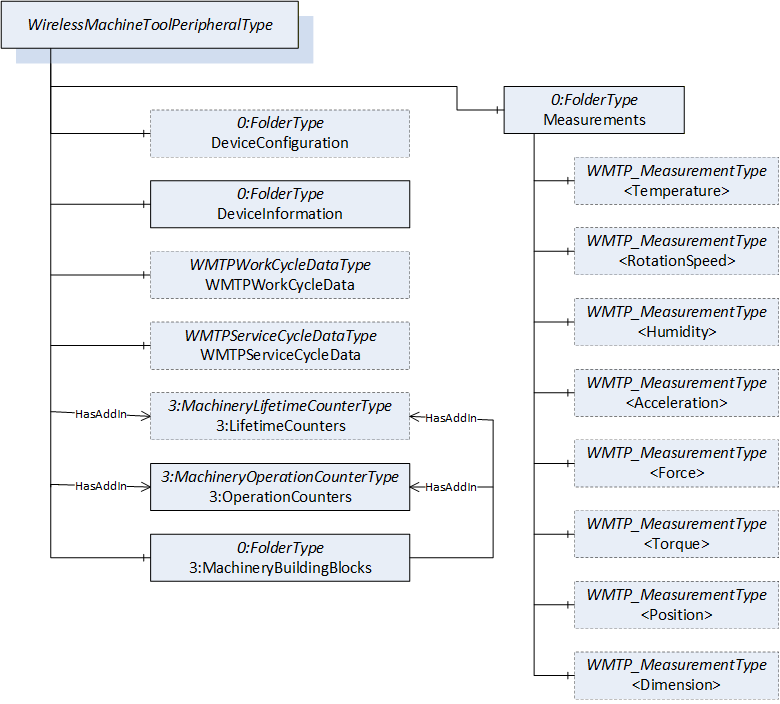
The resulting data of a WMTP, as well as the methods to be executed on it, are assigned to the respective FolderType Objects.
The FolderType DeviceConfiguration provides methods and variables relating to the configuration of a WMTP. In addition to WMTP identification data, the DeviceInformation FolderType object also provides information on the battery level and information on the device license and life cycle, for example.
The FolderType Measurements contains all measured values actually recorded by the WMTP. Depending on the application, a WMTP can potentially record a large number of different measured values. First and foremost, these are explicitly temperature, rotation speed, humidity, acceleration and vibration, applied force, torque, the position of a reference point and the dimension. All these measurements can be implemented with one developed ObjectType for measurements, called WMTPMeasurementType. Instances of these measurements shall be located in the FolderType Measurements. The WMTPMeasurementType is a subtype of the ProcessValueType defined in "OPC UA for Machinery - Part 2: Process Values" (OPC 40001-2).
With the use of the two ObjectTypes WMTPWorkCycleDateType and WMTPServiceCycleDataType, desired data and service records can be transferred or deleted from the WMTP. The data is sent by the WMTP to the Client in response to the method used, the data is not stored to a specific node of the information model.
On Figure 6 you can see an overview of the WirelessMachineToolPeripheralType.
7 OPC UA ObjectTypes
Figure 7 shows all ObjectTypes which are defined by this companion specification.
7.1 WirelessMachineToolPeripheralType ObjectType Definition
7.1.1 Overview
The WirelessMachineToolPeripheralType provides information about the WMTP itself. This ObjectType is the entry point to the OPC UA interface of a WMTP. An instance of this ObjectType aggregates all information related to one system.
It is highly recommended that all instances of a WirelessMachineToolPeripheralType are referenced from the 3:Machines node defined in OPC 40001-1.
The WirelessMachineToolPeripheralType is formally defined in Table 15.
| Attribute | Value | ||||
| BrowseName | WirelessMachineToolPeripheralType | ||||
| IsAbstract | False | ||||
| References | Node Class | BrowseName | DataType | TypeDefinition | Other |
|---|---|---|---|---|---|
| Subtype of the BaseObjectType defined in OPC 10000-5 | |||||
| 0:HasComponent | Object | DeviceConfiguration | 0:FolderType | O | |
| 0:HasComponent | Object | DeviceInformation | 0:FolderType | M | |
| 0:HasComponent | Object | WMTPWorkCycleData | WMTPWorkCycleDataType | O | |
| 0:HasComponent | Object | WMTPServiceCycleData | WMTPServiceCycleDataType | O | |
| 0:HasAddIn | Object | 3:LifetimeCounters | 3:MachineryLifetimeCounterType | O | |
| 0:HasAddIn | Object | 3:OperationCounters | 3:MachineryOperationCounterType | O | |
| 0:HasComponent | Object | Measurements | 0:FolderType | M | |
| 0:HasComponent | Object | 3:MachineryBuildingBlocks | 0:FolderType | M | |
| Conformance Units | |||||
|---|---|---|---|---|---|
| WMTP Basic | |||||
| WMTP DeviceConfiguration Calibration Capabilities | |||||
| WMTP DeviceConfiguration Time Capabilities | |||||
| WMTP Firmware Services | |||||
| WMTP License Services | |||||
| WMTP BatteryLevel | |||||
| WMTP Service and LifeCycle Information Basic | |||||
| WMTP Service and LifeCycle Information Advanced | |||||
| WMTP Temperature Measurement | |||||
| WMTP RotationSpeed Measurement | |||||
| WMTP Humidity Measurement | |||||
| WMTP Acceleration Measurement | |||||
| WMTP Force Measurement | |||||
| WMTP Torque Measurement | |||||
| WMTP Position Measurement | |||||
| WMTP Dimension Measurement | |||||
| WMTP WorkCycleData | |||||
| WMTP ServiceCycleData |
DeviceConfiguration is representing a collection of all nodes that enable configuration or provide information on the configuration of a WMTP.
DeviceInformation is representing a collection of all nodes that provide information about the WMTP.
WMTPWorkCycleData enables the handling of measured work cycles.
WMTPServiceCycleData enables the handling of service data of the WMTP.
MachineryLifetimeCounters is representing a collection of all counters with a start and an end value. It is used as the MachineryLifetimeCounterType defined in OPC 40001-1. In the information model for WMTP, all counters that are implemented according to the MachineryLifetimeCounterType of the OPC 40001-1 shall be integrated with the HasComponent reference under this Object. This Object shall also be referenced as HasAddIn in the MachineryBuildingBlocks Folder.
MachineryOperationCounters is representing a collection of all incrementing counters. It is used as the MachineryOperationCounterType defined in OPC 40001-1. In the information model for WMTP, all counters that are implemented according to the MachineryLifetimeCounterType of the OPC 40001-1 shall be integrated with the HasComponent reference under this Object. This Object shall also be referenced as HasAddIn in the MachineryBuildingBlocks Folder.
Measurements is representing a collection of all nodes that provide values measured by the WMTP, such as temperature, rotation speed, humidity, etc.
MachineryBuildingBlocks is representing a folder that directly references all those building blocks of the OPC UA for Machinery (OPC 40001-1, OPC 40001-3) which are implemented with an HasAddIn reference in this information model.
The components of the WirelessMachineToolPeripheralType have additional references which are defined in Table 16.
| SourceBrowsePath | Reference Type | Is Forward | TargetBrowsePath | ||
| 3:MachineryBuildingBlocks | 0:HasAddIn | True |
| ||
| 3:MachineryBuildingBlocks | 0:HasAddIn | True | 3:LifetimeCounters | ||
| 3:MachineryBuildingBlocks | 0:HasAddIn | True | 3:OperationCounters |
The components of the WirelessMachineToolPeripheralType have additional subcomponents which are defined in Table 17.
| Source Path | Reference | NodeClass | BrowseName | DataType | TypeDefinition | Others |
| DeviceConfiguration | 0:HasProperty | Variable | CalibrationMode | 0:Boolean | 0:PropertyType | O |
| DeviceConfiguration | 0:HasComponent | Method | SetDeviceTime | O | ||
| DeviceConfiguration | 0:HasComponent | Method | UpdateFirmware | O | ||
| DeviceConfiguration | 0:HasComponent | Method | SendLicenseData | O | ||
| DeviceConfiguration | 0:HasComponent | Method | SwitchCalibrationMode | O | ||
| DeviceInformation | 0:HasAddIn | Object | 2:Identification | 3:MachineryComponentIdentificationType | M | |
| DeviceInformation | 0:HasComponent | Object | BatteryLevel | 6:ProcessValueType | O | |
| DeviceInformation | 0:HasProperty | Variable | LicenseInformation | 0:String | 0:PropertyType | O |
| DeviceInformation | 0:HasProperty | Variable | NextServiceDate | 0:UtcTime | 0:PropertyType | O |
| DeviceInformation | 0:HasProperty | Variable | LastService | 0:UtcTime | 0:PropertyType | O |
| DeviceInformation | 0:HasComponent | Variable | LifeCycleStatus | 0:UInt32 | 0:MultiStateValueDiscreteType | O |
| 3:LifetimeCounters | 0:HasComponent | Variable | LicenseValidity | 0:Number | 2:LifetimeVariableType | O |
| 3:LifetimeCounters | 0:HasComponent | Variable | RemainingLifetimeCounter | 0:Number | 2:LifetimeVariableType | O |
| 3:LifetimeCounters | 0:HasComponent | Variable | RemainingCycleCounter | 0:Number | 2:LifetimeVariableType | O |
| 3:LifetimeCounters | 0:HasComponent | Variable | NextServiceCounter | 0:Number | 2:LifetimeVariableType | O |
| 3:OperationCounters | 0:HasComponent | Variable | OperationSinceLastServiceCounter | 0:Duration | 0:BaseDataVariableType | O |
| Measurements | 0:HasComponent | Object | <Temperature> | WMTPMeasurementType | OP | |
| Measurements | 0:HasComponent | Object | <RotationSpeed> | WMTPMeasurementType | OP | |
| Measurements | 0:HasComponent | Object | <Humidity> | WMTPMeasurementType | OP | |
| Measurements | 0:HasComponent | Object | <Acceleration> | WMTPMeasurementType | OP | |
| Measurements | 0:HasComponent | Object | <Force> | WMTPMeasurementType | OP | |
| Measurements | 0:HasComponent | Object | <Torque> | WMTPMeasurementType | OP | |
| Measurements | 0:HasComponent | Object | <Position> | WMTPMeasurementType | OP | |
| Measurements | 0:HasComponent | Object | <Dimension> | WMTPMeasurementType | OP |
CalibrationMode indicates whether the device is currently in calibration mode or not. True means the WMTP is in calibration mode.
SetDeviceTime enables writing the current date and time on the WMTP.
UpdateFirmware enables transferring a new firmware to the WMTP. Possible implementation or monitoring of the installation takes place independently of OPC UA on the respective WMTP and is solved differently by different manufacturers.
SendLicenseData enables transferring license data to the WMTP. Possible implementation or monitoring of the installation takes place independently of OPC UA on the respective WMTP and is solved differently by different manufacturers.
SwitchCalibrationMode enables the WMTP to be switched to calibration mode and back.
Identification is used as defined in OPC 40001-1 and shall also be referenced as AddIn in the
MachineryBuildingBlocks Folder.
BatteryLevel contains all data on the current battery level of the WMTP.
LicenseInformation contains information about the license of the WMTP. How this information looks like is solved differently by different manufacturers.
NextServiceDate is the date when the next maintenance is scheduled.
LastService is the date when the last maintenance of the device was carried out.
LifeCycleStatus is a parameter which outputs the life cycle in the form of four stages (unknown, green, yellow, red). This parameter is generated internally in the WMTP and is solved differently by different manufacturers.
LicenseValidity is used as the MachineryLifetimeCounterType is defined in OPC 40001-1. It is representing a counter that counts down a time value specified by the manufacturer of the WMTP. At the end of this period, the license of the WMTP Software is not valid anymore.
RemainingLifetimeCounter is used as the MachineryLifetimeCounterType is defined in OPC 40001-1. It is representing a counter that counts down a time value specified by the manufacturer of the WMTP. At the end of this period, the WMTP has reached its maximum lifetime.
RemainingCycleCounter is used as the MachineryLifetimeCounterType is defined in OPC 40001-1. It is representing a counter that counts down a number of working cycles specified by the manufacturer of the WMTP. At the end of this period, the WMTP has reached its maximum service life.
NextServiceCounter is used as the MachineryLifetimeCounterType is defined in OPC 40001-1. It is representing a counter that counts down a time value specified by the manufacturer of the WMTP. A service is to be carried out when this time period expires.
OperationSinceLastServiceCounter is representing a counter that counts the duration of use since the last service of the WMTP.
Temperature contains all data on the measured temperature.
RotationSpeed contains all data on the measured rotational speed.
Humidity contains all data on the measured humidity.
Acceleration contains all data on the measured acceleration of the WMTP.
Force contains all data on the measured force.
Torque contains all data on the measured torque.
Position contains all data on the measured position of the WMTP.
Dimension contains all data on the measured dimension.
NOTE: The list of measurements is representing the most used types. The model can be extended as required by the end user.
A child Node of the WirelessMachineToolPeripheralType has an additional Attribute value defined in Table 18.
| BrowsePath | Value Attribute | Description Attribute | |||
| [ {"Value": 0, "DisplayName": "green", "Description": ""}, {"Value": 1, "DisplayName": "yellow", "Description": ""}, {"Value": 2, "DisplayName": "red", "Description": ""}, ] |
7.1.2 SetDeviceTime
The Method SetDeviceTime allows to set the device time. The signature of this Method is specified below.
Signature
	SetDeviceTime (
		[in]	0:DateTime		DateTime,
		[in]	0:TimeZoneDataType	TimeZoneOffset
	);
| Argument | Description |
| DateTime | Date and time in UTC time |
| TimeZoneOffset | Time difference from UTC in minutes |
| Attribute | Value | ||||
| BrowseName | SetDeviceTime | ||||
| References | Node Class | BrowseName | DataType | TypeDefinition | Other |
|---|---|---|---|---|---|
| 0:HasProperty | Variable | InputArguments | Argument[] | 0:PropertyType | M |
NOTE: A call with DateTime = "2024-02-03 12:00" (UTC time) and TimeZoneOffset = {120; true}, sets the (local) machine time to "03-02-2024 14:00" and the time zone to "UTC+2".
7.1.3 UpdateFirmware
The Method UpdateFirmware sends a new firmware to be transferred to the WMTP. The signature of this Method is specified below.
Signature
	UpdateFirmware (
		[in]	0:Byte[]	FirmwareData
	);
| Argument | Description |
| FirmwareData | This array of bytes contains the corresponding firmware to be loaded onto the WMTP. |
| Attribute | Value | ||||
| BrowseName | UpdateFirmware | ||||
| References | Node Class | BrowseName | DataType | TypeDefinition | Other |
|---|---|---|---|---|---|
| 0:HasProperty | Variable | InputArguments | Argument[] | 0:PropertyType | M |
7.1.4 SendLicenseData
The Method SendLicenseData sends license data to the WMTP. The signature of this Method is specified below.
Signature
	SendLicenseData (
		[in]	0:Byte[]	LicenseData
	);
| Argument | Description |
| LicenseData | This array of bytes contains the corresponding license information to be transfered onto the WMTP. |
| Attribute | Value | ||||
| BrowseName | SendLicenseData | ||||
| References | Node Class | BrowseName | DataType | TypeDefinition | Other |
|---|---|---|---|---|---|
| 0:HasProperty | Variable | InputArguments | Argument[] | 0:PropertyType | M |
7.1.5 SwitchCalibrationMode
The Method SwitchCalibrationMode enables to switch the WMTP between "Calibrate" mode and "Use" mode. The signature of this Method is specified below.
Signature
	SwitchCalibrationMode (
		[in]	0:UInt16	TargetMode
	);
| Argument | Description |
| TargetMode | Describes the mode in which the WMTP is to be set. NOTE: The TargetMode is from DataType UInt16. Two different entries should be used: - 0 exit calibration mode - 1 enter calibration mode |
| Attribute | Value | ||||
| BrowseName | SwitchCalibrationMode | ||||
| References | Node Class | BrowseName | DataType | TypeDefinition | Other |
|---|---|---|---|---|---|
| 0:HasProperty | Variable | InputArguments | Argument[] | 0:PropertyType | M |
7.2 ObjectTypes for data transfer and management
7.2.1 WMTPWorkCycleDataType ObjectType Definition
The WMTPWorkCycleDataType provides the Methods that are required for reading out and deleting the work cycle data of a WMTP. It is formally defined in Table 27.
| Attribute | Value | ||||
| BrowseName | WMTPWorkCycleDataType | ||||
| IsAbstract | False | ||||
| References | Node Class | BrowseName | DataType | TypeDefinition | Other |
|---|---|---|---|---|---|
| Subtype of the BaseObjectType defined in OPC 10000-5 | |||||
| 0:HasComponent | Method | DeleteAllStoredRecords | O | ||
| 0:HasComponent | Method | DeleteStoredRecordsTime | O | ||
| 0:HasComponent | Method | DeleteStoredRecordsIndex | O | ||
| 0:HasComponent | Method | AbortOperation | M | ||
| 0:HasComponent | Method | ReportNumberOfStoredRecords | M | ||
| 0:HasComponent | Method | ReportNumberOfStoredRecordsTime | O | ||
| 0:HasComponent | Method | CombinedReportAll | M | ||
| 0:HasComponent | Method | CombinedReportIndex | O | ||
| 0:HasComponent | Method | CombinedReportTime | O | ||
| 0:HasComponent | Method | CombinedReportLastValue | O | ||
| 0:HasComponent | Method | CombinedReportFirstValue | O | ||
| Conformance Units | |||||
|---|---|---|---|---|---|
| WMTP WorkCycleData Deleting All | |||||
| WMTP WorkCycleData Deleting Advanced | |||||
| WMTP WorkCycleData ReportNumberOfStoredRecordsTime | |||||
| WMTP WorkCycleData CombinedReport Index | |||||
| WMTP WorkCycleData CombinedReport Time | |||||
| WMTP WorkCycleData CombinedReport Advanced |
DeleteAllStoredRecords enables to permanently delete all stored data from the WMTP.
DeleteStoredRecordsTime enables to permanently delete a desired section of stored data from the WMTP, chosen by the time of measurement.
DeleteStoredRecordsIndex enables to permanently delete a desired section of stored data from the WMTP, chosen by the index of measurement.
AbortOperation enables the termination of the process currently being executed by the WMTP. This is necessary as some transfer processes can take several minutes.
ReportNumberOfStoredRecords enables querying the number of data records available on the WMTP.
ReportNumberOfStoredRecordsTime enables querying the number of data records available on the WMTP according to a given timespan.
CombinedReportAll enables to request all stored data from the WMTP.
CombinedReportIndex enables to request the stored data from the WMTP according to the index of the measurements. Using this method, it is possible to request the entire data set as well as desired sections.
CombinedReportTime enables to request the stored data from the WMTP according to the timestamp of the measurements. Using this method, it is possible to request the entire data set as well as desired sections.
7.2.2 WMTPServiceCycleDataType ObjectType Definition
The WMTPServiceCycleDataType provides the Methods that are required for reading out and deleting the service cycle data of a WMTP. It is formally defined in Table 28.
| Attribute | Value | ||||
| BrowseName | WMTPServiceCycleDataType | ||||
| IsAbstract | False | ||||
| References | Node Class | BrowseName | DataType | TypeDefinition | Other |
|---|---|---|---|---|---|
| Subtype of the BaseObjectType defined in OPC 10000-5 | |||||
| 0:HasComponent | Method | DeleteAllStoredRecords | O | ||
| 0:HasComponent | Method | DeleteStoredRecordsTime | O | ||
| 0:HasComponent | Method | DeleteStoredRecordsIndex | O | ||
| 0:HasComponent | Method | AbortOperation | M | ||
| 0:HasComponent | Method | ReportNumberOfStoredRecords | M | ||
| 0:HasComponent | Method | ReportNumberOfStoredRecordsTime | O | ||
| 0:HasComponent | Method | CombinedReportAll | M | ||
| 0:HasComponent | Method | CombinedReportIndex | O | ||
| 0:HasComponent | Method | CombinedReportTime | O | ||
| 0:HasComponent | Method | CombinedReportLastValue | O | ||
| 0:HasComponent | Method | CombinedReportFirstValue | O | ||
| Conformance Units | |||||
|---|---|---|---|---|---|
| WMTP ServiceCycleData Deleting All | |||||
| WMTP ServiceCycleData Deleting Advanced | |||||
| WMTP ServiceCycleData ReportNumberOfStoredRecordsTime | |||||
| WMTP ServiceCycleData CombinedReport Index | |||||
| WMTP ServiceCycleData CombinedReport Time | |||||
| WMTP ServiceCycleData CombinedReport Advanced |
DeleteStoredAllRecords enables to permanently delete all stored data from the WMTP. Using this method, it is possible to remove the entire data set as well as desired sections.
DeleteStoredRecordsTime enables to permanently delete a desired section of stored data from the WMTP, chosen by the time of measurement.
DeleteStoredRecordsNumber enables to permanently delete a desired section of stored data from the WMTP, chosen by the index of measurement.
AbortOperation enables the termination of the process currently being executed by the WMTP. This is necessary as some transfer processes can take several minutes.
ReportNumberOfStoredRecords enables querying the number of data records available on the WMTP.
ReportNumberOfStoredRecordsTime enables querying the number of data records available on the WMTP according to a given timespan.
CombinedReportAll enables to request all stored data from the WMTP.
CombinedReportIndex enables to request the stored data from the WMTP according to the index of the measurements. Using this method, it is possible to request the entire data set as well as desired sections.
CombinedReportTime enables to request the stored data from the WMTP according to the timestamp of the measurements. Using this method, it is possible to request the entire data set as well as desired sections.
7.2.3 Methods used for data transfer and management
7.2.3.1 DeleteAllStoredRecords
The Method DeleteAllStoredRecords enables to permanently delete all stored data from the WMTP. Using this method, it is possible to remove the entire data set. The signature of this Method is specified below.
Signature
	DeleteAllStoredRecords (
	);
7.2.3.2 DeleteStoredRecordsTime
The Method DeleteStoredRecordsTime enables to permanently delete the stored data from the WMTP from a specific given time. The signature of this Method is specified below.
Signature
	DeleteStoredRecordsTime (
		[in]	0:DateTime	FromTimestamp,
		[in]	0:DateTime	ToTimestamp,
	);
| Argument | Description |
| FromTimestamp | This timestamp defines the start of the time interval that is to be deleted |
| ToTimestamp | This timestamp defines the end of the time interval that is to be deleted |
| Attribute | Value | ||||
| BrowseName | DeleteStoredRecordsTime | ||||
| References | Node Class | BrowseName | DataType | TypeDefinition | Other |
|---|---|---|---|---|---|
| 0:HasProperty | Variable | InputArguments | Argument[] | 0:PropertyType | M |
7.2.3.3 DeleteStoredRecordsIndex
The Method DeleteStoredRecordsIndex enables to permanently delete the stored data from the WMTP from a specific given time. The signature of this Method is specified below.
Signature
	DeleteStoredRecordsIndex (
		[in]	0:UInt32	FromIndex,
		[in]	0:UInt32	ToIndex,
	);
| Argument | Description |
| FromIndex | This number defines the index of the first stored value of the interval that is to be deleted |
| ToIndex | This number defines the index of the last stored value of the interval that is to be deleted |
| Attribute | Value | ||||
| BrowseName | DeleteStoredRecordsIndex | ||||
| References | Node Class | BrowseName | DataType | TypeDefinition | Other |
|---|---|---|---|---|---|
| 0:HasProperty | Variable | InputArguments | Argument[] | 0:PropertyType | M |
7.2.3.4 AbortOperation
The Method AbortOperation enables the termination of the process currently being executed by the WMTP. This is necessary as some transfer processes can take several minutes. The signature of this Method is specified below.
Signature
	AbortOperation (
	);
7.2.3.5 ReportNumberOfStoredRecords
The Method ReportNumberOfStoredRecords enables to report how many records are currently stored at the WMTP.
Signature
	ReportNumberOfStoredRecords (
		[out]	0:UInt32	NumberOfStoredRecords);
| Argument | Description |
| NumberOfStoredRecords | Describes the number of currently stored values on the WMTP. |
| Attribute | Value | ||||
| BrowseName | ReportNumberOfStoredRecords | ||||
| References | Node Class | BrowseName | DataType | TypeDefinition | Other |
|---|---|---|---|---|---|
| 0:HasProperty | Variable | OutputArguments | Argument[] | 0:PropertyType | M |
7.2.3.6 ReportNumberOfStoredRecordsTime
The Method ReportNumberOfStoredRecordsTime enables to report how many records are currently stored at the WMTP in a specific timespan.
Signature
	ReportNumberOfStoredRecordsTime (
		[in]	0:DateTime	FromTimestamp,
		[in]	0:DateTime	ToTimestamp,
		[out]	0:UInt32	NumberOfStoredRecords);
| Argument | Description |
| FromTimestamp | This timestamp defines the time of the first stored value of the interval that is to be accessed. |
| ToTimestamp | This timestamp defines the time of the last stored value of the interval that is to be accessed. |
| NumberOfStoredRecords | Describes the number of currently stored values on the WMTP in the timespan. |
| Attribute | Value | ||||
| BrowseName | ReportNumberOfStoredRecordsTime | ||||
| References | Node Class | BrowseName | DataType | TypeDefinition | Other |
|---|---|---|---|---|---|
| 0:HasProperty | Variable | InputArguments | Argument[] | 0:PropertyType | M |
| 0:HasProperty | Variable | OutputArguments | Argument[] | 0:PropertyType | M |
7.2.3.7 CombinedReportAll
The Method CombinedReportAll enables access to the entire data set stored on the WMTP. A record transfer is defined within this specification as a transfer of a "copy" of the records and not a "move" of the records because the server retains the original log entries. The signature of this Method is specified below.
Signature
	CombinedReportAll (
		[out]	WMTPOutputDataType[]	CombinedReport
	);
| Argument | Description |
| CombinedReport | This output argument is carrying the Variables of the DataType WMTPOutputDataType that are requested |
| Attribute | Value | ||||
| BrowseName | CombinedReportAll | ||||
| References | Node Class | BrowseName | DataType | TypeDefinition | Other |
|---|---|---|---|---|---|
| 0:HasProperty | Variable | OutputArguments | Argument[] | 0:PropertyType | M |
NOTE: If all measured values exceed the maximum size of an OPC UA message, this method cannot be used. In this case, the data should be queried in packets, for example using the CombinedReportIndex.
7.2.3.8 CombinedReportIndex
The Method CombinedReportIndex enables access to the entire data set stored on the WMTP based on the index of the measurements. A record transfer is defined within this specification as a transfer of a "copy" of the records and not a "move" of the records because the server retains the original log entries. The signature of this Method is specified below.
Signature
	CombinedReportIndex (
		[in]	0:UInt32	FromIndex,
		[in]	0:UInt32	ToIndex,
		[out]	WMTPOutputDataType[]	CombinedReport
	);
| Argument | Description |
| FromIndex | This number defines the index of the first stored value of the interval that is to be accessed |
| ToIndex | This number defines the index of the last stored value of the interval that is to be accessed |
| CombinedReport | This output argument is carrying the Variables of the DataType WMTPOutputDataType that are requested |
| Attribute | Value | ||||
| BrowseName | CombinedReportIndex | ||||
| References | Node Class | BrowseName | DataType | TypeDefinition | Other |
|---|---|---|---|---|---|
| 0:HasProperty | Variable | InputArguments | Argument[] | 0:PropertyType | M |
| 0:HasProperty | Variable | OutputArguments | Argument[] | 0:PropertyType | M |
7.2.3.9 CombinedReportLastValue
The Method CombinedReportLastValue enables access to the last measurement stored on the WMTP. A record transfer is defined within this specification as a transfer of a "copy" of the records and not a "move" of the records because the server retains the original log entries. The signature of this Method is specified below.
Signature
	CombinedReportLastValue (
		[out]	WMTPOutputDataType	CombinedReport
	);
| Argument | Description |
| CombinedReport | This output argument is carrying the Variables of the DataType WMTPOutputDataType that are requested |
| Attribute | Value | ||||
| BrowseName | CombinedReportLastValue | ||||
| References | Node Class | BrowseName | DataType | TypeDefinition | Other |
|---|---|---|---|---|---|
| 0:HasProperty | Variable | OutputArguments | Argument[] | 0:PropertyType | M |
7.2.3.10 CombinedReportFirstValue
The Method CombinedReportFirstValue enables access to the first measurement stored on the WMTP. A record transfer is defined within this specification as a transfer of a "copy" of the records and not a "move" of the records because the server retains the original log entries. The signature of this Method is specified below.
Signature
	CombinedReportFirstValue (
		[out]	WMTPOutputDataType	CombinedReport
	);
| Argument | Description |
| CombinedReport | This output argument is carrying the Variables of the DataType WMTPOutputDataType that are requested |
| Attribute | Value | ||||
| BrowseName | CombinedReportFirstValue | ||||
| References | Node Class | BrowseName | DataType | TypeDefinition | Other |
|---|---|---|---|---|---|
| 0:HasProperty | Variable | OutputArguments | Argument[] | 0:PropertyType | M |
7.2.3.11 CombinedReportTime
The Method CombinedReportTime enables access to the entire data set stored on the WMTP based on the timestamp of the measurements. A record transfer is defined within this specification as a transfer of a "copy" of the records and not a "move" of the records because the server retains the original log entries. The signature of this Method is specified below.
Signature
	CombinedReportTime (
		[in]	0:DateTime	FromTimestamp,
		[in]	0:DateTime	ToTimestamp,
		[out]	WMTPOutputDataType[]	CombinedReport

	);
| Argument | Description |
| FromTimestamp | This timestamp defines the time of the first stored value of the interval that is to be accessed |
| ToTimestamp | This timestamp defines the time of the last stored value of the interval that is to be accessed |
| CombinedReport | This output argument is carrying the Variables of the DataType WMTPOutputDataType that are requested |
| Attribute | Value | ||||
| BrowseName | CombinedReportTime | ||||
| References | Node Class | BrowseName | DataType | TypeDefinition | Other |
|---|---|---|---|---|---|
| 0:HasProperty | Variable | InputArguments | Argument[] | 0:PropertyType | M |
| 0:HasProperty | Variable | OutputArguments | Argument[] | 0:PropertyType | M |
7.3 WMTPMeasurementType ObjectType Definition
7.3.1 Overview
The WMTPMeasurementType is a subtype of the ProcessValueType defined in OPC 40001-2.
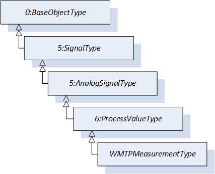
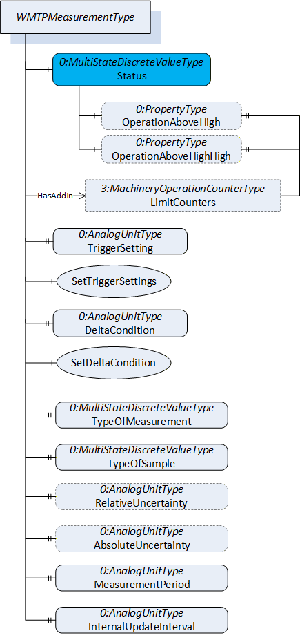
Figure 9 shows an overview of the WMTPMeasurementType. The blue marked Variables 5:AnalogSignal and Status are inherited from the respective supertypes and are complemented by the WMTPMeasurementType.
The WMTPMeasurementType is formally defined in Table 47.
| Attribute | Value | ||||
| BrowseName | WMTPMeasurementType | ||||
| IsAbstract | False | ||||
| References | Node Class | BrowseName | DataType | TypeDefinition | Other |
|---|---|---|---|---|---|
| Subtype of the ProcessValueType defined in "OPC UA for Machinery - Part 2: Process Values" (OPC 40001-2) | |||||
| 0:HasComponent | Object | LimitCounters | 3:MachineryOperationCounterType | O | |
| 0:HasComponent | Variable | TriggerSettings | 0:UInt32 | 0:AnalogUnitType | M |
| 0:HasComponent | Method | SetTriggerSettings | M | ||
| 0:HasComponent | Variable | DeltaCondition | 0:Double | 0:AnalogUnitType | M |
| 0:HasComponent | Method | SetDeltaCondition | M | ||
| 0:HasComponent | Variable | TypeOfMeasurement | 0:UInt32 | 0:MultiStateValueDiscreteType | M |
| 0:HasComponent | Variable | TypeOfSample | 0:UInt32 | 0:MultiStateValueDiscreteType | M |
| 0:HasComponent | Variable | RelativeUncertainty | 0:Double | 0:AnalogUnitType | O |
| 0:HasComponent | Variable | AbsoluteUncertainty | 0:Double | 0:AnalogUnitType | O |
| 0:HasProperty | Variable | Timestamp | 0:DateTime | 0:PropertyType | O |
| 0:HasProperty | Variable | Index | 0:UInt32 | 0:PropertyType | O |
| 0:HasProperty | Variable | MeasurementPeriod | 0:Duration | 0:PropertyType | O |
| 0:HasProperty | Variable | InternalUpdateInterval | 0:Duration | 0:PropertyType | O |
| 0:HasComponent | Variable | 6:Status | 0:UInt16 | 0:MultiStateValueDiscreteType | O |
| Conformance Units | |||||
|---|---|---|---|---|---|
| WMTP Measurement LimitCounters | |||||
| WMTP Measurement InternalUpdateInterval | |||||
| WMTP Measurement Information for WorkCycleData |
LimitCounters is used as the MachineryOperationCounterType defined in OPC 40001-1. The WMTPMeasurementType is using the LimitCounters to structure the two counters OperationAboveHigh and OperationAboveHighHigh. The LimitCounters shall also be referenced as AddIn in the MachineryBuildingBlocks Folder to provide better access from a higher level.
TriggerSettings represents the time period from one measurement point to the next. If the relevant sensor of the WMTP does not define the measurement triggering using the TriggerSettings, the default value 0 shall be assumed.
SetTriggerSettings enables the TriggerSettings to be adjusted.
DeltaCondition represents the delta value that needs to be reached before the WMTP triggers the next measurement transmission. If the relevant sensor of the WMTP does not define the measurement triggering using the DeltaCondition, the default value 0 shall be assumed.
SetDeltaCondition enables the DeltaCondition to be adjusted.
NOTE: A WMTP sensor requires at least one value for the TriggerSettings or the DeltaCondition, as these variables are used to determine the measuring frequency. It is also possible to convert both conditions. If one of the variables is not required, the default value must be set for this variable. It must be ensured that both values are not zero at the same time.
TypeOfMeasurement describes which physical type of measurement is represented by this Instance of the WMTPMeasurementType. A list of possible options can be found in Table 48.
TypeOfSample defines the category of the measurement set. This specification defines standardized values for resources Table 48.
RelativeUncertainty is representing the percent uncertainty of measurement.
AbsoluteUncertainty is representing the measurement error in the same unit as the measured value.
Timestamp is representing the exact time of the measurement. Since the WMTP collects the data at a different time than when it is transferred to the OPC UA server, the time of data collection should be stored within this property.
Index is representing the number of the measurement.
MeasurementPeriod defines the time period over which the WMTPMeasurementType was recorded.
InternalUpdateInterval defines the sampling rate of the sensor.
Status is inherited from the from OPC 40001-2.
NOTE: The 6:ProcessValueType already provides the Variable SignalTag from the Object SignalType (OPC 30081), which can be used by inheritance in subtypes, is used to describe the location of the measurement. This variable can be used, for example, if several sensors are installed and the measured values must be clearly assignable.
NOTE: The 6:ProcessValueType already provides the Variable ValuePrecision from the Object 0:DataItemType, which can be used by inheritance in subtypes, is used to describe the precision (resolution) of the measured value or the sensor. It specifies the smallest increment of the measurement.
A Node of the WMTPMeasurementType has an additional Attribute value defined in Table 48.
| BrowsePath | Value Attribute | Description Attribute | ||
| [ {"Value": 0, "DisplayName": "temperature", "Description": ""}, {"Value": 1, "DisplayName": "rotation speed", "Description": ""}, {"Value": 2, "DisplayName": "humidity", "Description": ""}, {"Value": 3, "DisplayName": "acceleration", "Description": ""}, {"Value": 4, "DisplayName": "force", "Description": ""}, {"Value": 5, "DisplayName": "torque", "Description": ""}, {"Value": 6, "DisplayName": "position", "Description": ""}, {"Value": 7, "DisplayName": "dimension", "Description": ""}, ] | |||
| [ {"Value": 0, "DisplayName": "unspecified", "Description": ""}, {"Value": 1, "DisplayName": "instantaneous", "Description": ""}, {"Value": 2, "DisplayName": "arithmetic mean since the beginning of the work cycle", "Description": ""}, {"Value": 3, "DisplayName": "root mean square (RMS) value since the beginning of the work cycle", "Description": ""}, {"Value": 4, "DisplayName": "maximum value in the current work cycle", "Description": ""}, {"Value": 5, "DisplayName": "minimum value in the current work cycle", "Description": ""}, {"Value": 6, "DisplayName": "moving average", "Description": ""}, ] |
The components of the WMTPMeasurementType have additional subcomponents which are defined in Table 49.
| Source Path | Reference | NodeClass | BrowseName | DataType | TypeDefinition | Others |
| 6:Status | 0:HasProperty | Variable | OperationAboveHigh | 0:Duration | 0:PropertyType | O |
| 6:Status | 0:HasProperty | Variable | OperationAboveHighHigh | 0:Duration | 0:PropertyType | O |
OperationAboveHigh represents a counter that records the time that the Status variable has the value 9 (ABOVE_HIGH_LIMIT) or 10 (ABOVE_HIGHHIGH_LIMIT). All the different statuses are defined in OPC 40001-2.
OperationAboveHighHigh represents a counter that records the time that the Status variable has the value 10 (ABOVE_HIGHHIGH_LIMIT). All the different statuses are defined in OPC 40001-2.
NOTE: The WMTPMeasurementType is a subtype of the ProcessValueType from OPC 40001-2. The additional subcomponents mentioned above are referring to the mandatory 5:AnalogSignal Variable and the Status Variable of the ProcessValueType which are inherited to the WMTPMeasurementType.
The components of the WMTPMeasurementType have additional references which are defined in Table 50.
| SourceBrowsePath | Reference Type | Is Forward | TargetBrowsePath | |||
| LimitCounters | 0:HasProperty | True |
| |||
| LimitCounters | 0:HasProperty | True |
|
7.3.2 SetTriggerSettings
The Method SetTriggerSettings enables to adjust the trigger settings of the relevant sensor of the WMTP. TriggerSettings represents the time period from one measurement point to the next. If the relevant sensor of the WMTP does not define the measurement triggering using the TriggerSettings, the default value 0 shall be assumed.
Signature
	SetTriggerSettings (
		[in]	0:Duration	TriggerDuration
	);
| Argument | Description |
| TriggerDuration | This Duration represents the time period between measurements. |
| Attribute | Value | ||||
| BrowseName | SetTriggerSettings | ||||
| References | Node Class | BrowseName | DataType | TypeDefinition | Other |
|---|---|---|---|---|---|
| 0:HasProperty | Variable | InputArguments | Argument[] | 0:PropertyType | M |
7.3.3 SetDeltaCondition
The Method SetDeltaCondition enables to adjust the delta condition of the relevant sensor of the WMTP. DeltaCondition represents the delta value that needs to be reached before the WMTP triggers the next measurement transmission. If the relevant sensor of the WMTP does not define the measurement triggering using the DeltaCondition, the default value 0 shall be assumed.
Signature
	SetDeltaCondition (
		[in]	0:Number	DeltaValue
	);


NOTE: The DeltaValue parameter must be adapted to the existing measured value of the WMTPMeasurementType. The EngineeringUnit and the DataType of the number must therefore also be used here in this input parameter of the method.| Argument | Description |
| DeltaValue | This value represents the new delta between one measurement point to the next that has to be set. |
| Attribute | Value | ||||
| BrowseName | SetDeltaCondition | ||||
| References | Node Class | BrowseName | DataType | TypeDefinition | Other |
|---|---|---|---|---|---|
| 0:HasProperty | Variable | InputArguments | Argument[] | 0:PropertyType | M |
8 OPC UA DataTypes
8.1 WMTPOutputDataType
The WMTPOutputDataType represents a structure that defines optional and mandatory variables that can be output when querying a WMTP. All contained entries in the structure are nodes of the WMTPMeasurementType or one of its supertypes. The structure is defined in Table 55.
| Name | Type | Description | Optional |
| WMTPOutputDataType | structure | ||
EngineeringUnits | 0:EUInformation | False | |
ActualValue | 0:Double | False | |
TypeOfMeasurement | 0:UInt32 | False | |
TypeOfSample | 0:UInt32 | False | |
InstrumentRange | 0:Range | False | |
EURange | 0:Range | False | |
ValuePrecision | 0:Double | False | |
Definition | 0:String | False | |
SignalTag | 0:String | False | |
RelativeUncertainty | 0:Double | False | |
AbsoluteUncertainty | 0:Double | False | |
Timestamp | 0:DateTime | False | |
Index | 0:UInt32 | False | |
MeasurementPeriod | 0:Duration | False | |
InternalUpdateInterval | 0:Duration | False |
NOTE: Many controllers/embedded devices do not yet support structures with optional entries. To ensure that such devices can also interpret the present structure, all entries have been set as mandatory. The entries EngineeringUnits, ActualValue, TypeOfMeasurement, and TypeOfSample should always be set. However, if the remaining entries are not required, they can also be set to the default value 0.
Its representation in the AddressSpace is defined in Table 56.
| Attribute | Value | ||||
| BrowseName | WMTPOutputDataType | ||||
| IsAbstract | False | ||||
| References | Node Class | BrowseName | DataType | TypeDefinition | Other |
|---|---|---|---|---|---|
| Subtype of the 0:Structure defined in OPC 10000-5 | |||||
| Conformance Units | |||||
|---|---|---|---|---|---|
9 Profiles and ConformanceUnits
9.1 Conformance Units
This chapter defines the corresponding Conformance Units for the OPC UA Information Model for OPC UA for Wireless Machine Tool Peripherals.
| Category | Title | Description |
| Server | WMTP Basic | Type definition of WirelessMachineToolPeripheralType is available on the server. There is at least one instance of WirelessMachineToolPeripheralType. The instance has all mandatory nodes. |
| Server | WMTP DeviceConfiguration Calibration Capabilities | The WirelessMachineToolPeripheralType instance has the optional nodes for CalibrationMode and SwitchCalibrationMode. |
| Server | WMTP DeviceConfiguration Time Capabilities | The WirelessMachineToolPeripheralType instance has the optional node for SetDeviceTime. |
| Server | WMTP Firmware Services | The WirelessMachineToolPeripheralType instance has the optional node for UpdateFirmware. |
| Server | WMTP License Services | The WirelessMachineToolPeripheralType instance has the optional nodes for SendLicenseData, LicenseInformation and LicenseValidity. |
| Server | WMTP BatteryLevel | The WirelessMachineToolPeripheralType instance has the optional node for BatteryLevel. |
| Server | WMTP Service and LifeCycle Information Basic | The WirelessMachineToolPeripheralType instance has the optional nodes for NextServiceDate, LastService and LifeCycleStatus. |
| Server | WMTP Service and LifeCycle Information Advanced | The WirelessMachineToolPeripheralType instance has the optional nodes for NextServiceDate, LastService, LifeCycleStatus, RemainingLifetimeCounter, RemainingCycleCounter, NextServiceCounter, OperationCounter and OperationSinceLastServiceCounter. |
| Server | WMTP Temperature Measurement | The WirelessMachineToolPeripheralType instance has implemented an Object according to the WMTPMeasurementType that is tracking temperature data. |
| Server | WMTP RotationSpeed Measurement | The WirelessMachineToolPeripheralType instance has implemented an Object according to the WMTPMeasurementType that is tracking rotational speed data. |
| Server | WMTP Humidity Measurement | The WirelessMachineToolPeripheralType instance has implemented an Object according to the WMTPMeasurementType that is tracking humidity data. |
| Server | WMTP Acceleration Measurement | The WirelessMachineToolPeripheralType instance has implemented an Object according to the WMTPMeasurementType that is tracking acceleration data. |
| Server | WMTP Force Measurement | The WirelessMachineToolPeripheralType instance has implemented an Object according to the WMTPMeasurementType that is tracking force data. |
| Server | WMTP Torque Measurement | The WirelessMachineToolPeripheralType instance has implemented an Object according to the WMTPMeasurementType that is tracking torque data. |
| Server | WMTP Position Measurement | The WirelessMachineToolPeripheralType instance has implemented an Object according to the WMTPMeasurementType that is tracking position data. |
| Server | WMTP Dimension Measurement | The WirelessMachineToolPeripheralType instance has implemented an Object according to the WMTPMeasurementType that is tracking dimension data. |
| Server | WMTP WorkCycleData | The WirelessMachineToolPeripheralType instance has the optional node for WorkCycleData. |
| Server | WMTP ServiceCycleData | The WirelessMachineToolPeripheralType instance has the optional node for ServiceCycleData. |
| Server | WMTP WorkCycleData Deleting All | The WorkCycleDataType instance has the optional node for DeleteAllStoredRecords. |
| Server | WMTP WorkCycleData Deleting Advanced | The WorkCycleDataType instance has the optional nodes for DeleteAllStoredRecords, DeleteStoredRecordsTime and DeleteStoredRecordsIndex. |
| Server | WMTP WorkCycleData ReportNumberOfStoredRecordsTime | The WorkCycleDataType instance has the optional node for ReportNumberOfStoredRecordsTime. |
| Server | WMTP WorkCycleData CombinedReport Index | The WorkCycleDataType instance has the optional node for CombinedReportIndex. |
| Server | WMTP WorkCycleData CombinedReport Time | The WorkCycleDataType instance has the optional node for CombinedReportTime. |
| Server | WMTP WorkCycleData CombinedReport Advanced | The WorkCycleDataType instance has all optional nodes for the combined report. |
| Server | WMTP ServiceCycleData Deleting All | The ServiceCycleDataType instance has the optional node for DeleteAllStoredRecords. |
| Server | WMTP ServiceCycleData Deleting Advanced | The ServiceCycleDataType instance has the optional nodes for DeleteAllStoredRecords, DeleteStoredRecordsTime and DeleteStoredRecordsIndex. |
| Server | WMTP ServiceCycleData ReportNumberOfStoredRecordsTime | The ServiceCycleDataType instance has the optional node for ReportNumberOfStoredRecordsTime. |
| Server | WMTP ServiceCycleData CombinedReport Index | The ServiceCycleDataType instance has the optional node for CombinedReportIndex. |
| Server | WMTP ServiceCycleData CombinedReport Time | The ServiceCycleDataType instance has the optional node for CombinedReportTime. |
| Server | WMTP ServiceCycleData CombinedReport Advanced | The ServiceCycleDataType instance has all optional nodes for the combined report. |
| Server | WMTP Measurement LimitCounters | The WMTPMeasurementType instance has the optional node for LimitCounters. |
| Server | WMTP Measurement InternalUpdateInterval | The WMTPMeasurementType instance has the optional node for InternalUpdateInterval. |
| Server | WMTP Measurement Information for WorkCycleData | The WMTPMeasurementType instance has the optional nodes for Timestamp Index and MeasurementPeriod. |
9.2 Facets
9.2.1 Facet list
Table 58 lists all Facets defined in this document and defines their URIs.
9.2.2 Server Facets
9.2.2.1 Overview
The following sections specify the Facets available for Servers that implement the Wireless Machine Tool Peripherals companion specification. Each section defines and describes a Facet or Profile.
9.2.2.2 WMTP Basic Server Facet
This Facet defines support for base WMTP functionality.
| Group | Conformance Unit/ Facet Title | M / O |
| WMTP | WMTP Basic | M |
| WMTP | WMTP DeviceConfiguration Calibration Capabilities | O |
| WMTP | WMTP DeviceConfiguration Time Capabilities | O |
| WMTP | WMTP Firmware Services | O |
| WMTP | WMTP License Services | O |
| WMTP | WMTP BatteryLevel | O |
| WMTP | WMTP Measurement LimitCounters | O |
| WMTP | WMTP Measurement InternalUpdateInterval | O |
| WMTP | WMTP Measurement Information for WorkCycleData | O |
9.2.2.3 WMTP Service and LifeCycle Basic Facet
This Facet defines support for basic WMTP service and lifecycle data.
| Group | Conformance Unit/ Facet Title | M / O |
| WMTP | WMTP Basic | M |
| WMTP | WMTP Service and LifeCycle Information Basic | M |
9.2.2.4 WMTP Service and LifeCycle Advanced Facet
This Facet defines support for advanced WMTP service and lifecycle data.
| Group | Conformance Unit/ Facet Title | M / O |
| WMTP | WMTP Basic | M |
| WMTP | WMTP Service and LifeCycle Information Advanced | M |
9.2.2.5 WMTP Temperature Facet
This Facet defines support for at least one WMTP temperature measurement.
| Group | Conformance Unit/ Facet Title | M / O |
| WMTP | WMTP Basic | M |
| WMTP | WMTP Temperature Measurement | M |
9.2.2.6 WMTP Rotation Speed Facet
This Facet defines support for at least one WMTP rotational speed measurement.
| Group | Conformance Unit/ Facet Title | M / O |
| WMTP | WMTP Basic | M |
| WMTP | WMTP RotationSpeed Measurement | M |
9.2.2.7 WMTP Humidity Facet
This Facet defines support for at least one WMTP humidity measurement.
| Group | Conformance Unit/ Facet Title | M / O |
| WMTP | WMTP Basic | M |
| WMTP | WMTP Humidity Measurement | M |
9.2.2.8 WMTP Acceleration Facet
This Facet defines support for at least one WMTP acceleration measurement.
| Group | Conformance Unit/ Facet Title | M / O |
| WMTP | WMTP Basic | M |
| WMTP | WMTP Acceleration Measurement | M |
9.2.2.9 WMTP Force Facet
This Facet defines support for at least one WMTP force measurement.
| Group | Conformance Unit/ Facet Title | M / O |
| WMTP | WMTP Basic | M |
| WMTP | WMTP Force Measurement | M |
9.2.2.10 WMTP Torque Facet
This Facet defines support for at least one WMTP torque measurement.
| Group | Conformance Unit/ Facet Title | M / O |
| WMTP | WMTP Basic | M |
| WMTP | WMTP Torque Measurement | M |
9.2.2.11 WMTP Position Facet
This Facet defines support for at least one WMTP position measurement.
| Group | Conformance Unit/ Facet Title | M / O |
| WMTP | WMTP Basic | M |
| WMTP | WMTP Position Measurement | M |
9.2.2.12 WMTP Dimension Facet
This Facet defines support for at least one WMTP dimension measurement.
| Group | Conformance Unit/ Facet Title | M / O |
| WMTP | WMTP Basic | M |
| WMTP | WMTP Dimension Measurement | M |
9.2.2.13 WMTP Work Cycle Data Facet
This Facet defines support for handling the work cycle data of a WMTP.
| Group | Conformance Unit/ Facet Title | M / O |
| WMTP | WMTP Basic | M |
| WMTP | WMTP WorkCycleData | M |
| WMTP | WMTP WorkCycleData Deleting All | O |
| WMTP | WMTP WorkCycleData Deleting Advanced | O |
| WMTP | WMTP WorkCycleData ReportNumberOfStoredRecordsTime | O |
| WMTP | WMTP WorkCycleData CombinedReport Index | O |
| WMTP | WMTP WorkCycleData CombinedReport Time | O |
| WMTP | WMTP WorkCycleData CombinedReport Advanced | O |
9.2.2.14 WMTP Service Cycle Data Facet
This Facet defines support for handling the work cycle data of a WMTP.
| Group | Conformance Unit/ Facet Title | M / O |
| WMTP | WMTP Basic | M |
| WMTP | WMTP ServiceCycleData | M |
| WMTP | WMTP ServiceCycleData Deleting All | O |
| WMTP | WMTP ServiceCycleData Deleting Advanced | O |
| WMTP | WMTP ServiceCycleData ReportNumberOfStoredRecordsTime | O |
| WMTP | WMTP ServiceCycleData CombinedReport Index | O |
| WMTP | WMTP ServiceCycleData CombinedReport Time | O |
| WMTP | WMTP ServiceCycleData CombinedReport Advanced | O |
9.2.3 Client Facets
This specification does not define any Client Facets.
10 Namespaces
10.1 Namespace Metadata
Table 72 defines the namespace metadata for this document. The Object is used to provide version information for the namespace and an indication about static Nodes. Static Nodes are identical for all Attributes in all Servers, including the Value Attribute. See OPC 10000-5 for more details.
The information is provided as Object of type NamespaceMetadataType. This Object is a component of the Namespaces Object that is part of the Server Object. The NamespaceMetadataType ObjectType and its Properties are defined in OPC 10000-5.
The version information is also provided as part of the ModelTableEntry in the UANodeSet XML file. The UANodeSet XML schema is defined in OPC 10000-6.
| Attribute | Value | ||
| BrowseName | http://opcfoundation.org/UA/WMTP/ | ||
| Property | DataType | Value | |
|---|---|---|---|
| NamespaceUri | String | http://opcfoundation.org/UA/WMTP/ | |
| NamespaceVersion | String | 1.0.0 | |
| NamespacePublicationDate | DateTime | 2025-11-01 | |
| IsNamespaceSubset | Boolean | False | |
| StaticNodeIdTypes | IdType [] | 0 | |
| StaticNumericNodeIdRange | NumericRange [] | ||
| StaticStringNodeIdPattern | String | ||
10.2 Handling of OPC UA Namespaces
Namespaces are used by OPC UA to create unique identifiers across different naming authorities. The Attributes NodeId and BrowseName are identifiers. A Node in the UA AddressSpace is unambiguously identified using a NodeId. Unlike NodeIds, the BrowseName cannot be used to unambiguously identify a Node. Different Nodes may have the same BrowseName. They are used to build a browse path between two Nodes or to define a standard Property.
Servers may often choose to use the same namespace for the NodeId and the BrowseName. However, if they want to provide a standard Property, its BrowseName shall have the namespace of the standards body although the namespace of the NodeId reflects something else, for example the EngineeringUnits Property. All NodeIds of Nodes not defined in this document shall not use the standard namespaces.
Table 73 provides a list of mandatory and optional namespaces used in an OPC UA Server for WMTP.
| NamespaceURI | Description | Use |
| http://opcfoundation.org/UA/ | Namespace for NodeIds and BrowseNames defined in the OPC UA specification. This namespace shall have namespace index 0. | Mandatory |
| Local Server URI | Namespace for nodes defined in the local server. This namespace shall have namespace index 1. | Mandatory |
| http://opcfoundation.org/UA/DI/ | Namespace for NodeIds and BrowseNames defined in OPC 10000-100. The namespace index is Server specific. | Mandatory |
| http://opcfoundation.org/UA/Machinery/ | Namespace for NodeIds and BrowseNames defined in OPC UA for Machinery 40001-1. The namespace index is Server specific. | Mandatory |
| http://opcfoundation.org/UA/Dictionary/IRDI | Namespace for NodeIds of IRDI objects using HasDictionaryEntry. The namespace index is server specific. | Optional |
| http://opcfoundation.org/UA/PADIM/ | Namespace for NodeIds and BrowseNames defined in OPC UA for Process Automation Devices 30081. The namespace index is Server specific. | Mandatory |
| http://opcfoundation.org/UA/Machinery/ProcessValues/ | Namespace for NodeIds and BrowseNames defined in OPC UA for Machinery 40001-2. The namespace index is Server specific. | Mandatory |
| http://opcfoundation.org/UA/WMTP/ | Namespace for NodeIds and BrowseNames defined in this document. The namespace index is Server specific. | Mandatory |
| Vendor specific types | A Server may provide vendor-specific types like types derived from ObjectTypes defined in this document in a vendor-specific namespace. | Optional |
| Vendor specific instances | A Server provides vendor-specific instances of the standard types or vendor-specific instances of vendor-specific types in a vendor-specific namespace. It is recommended to separate vendor specific types and vendor specific instances into two or more namespaces. | Mandatory |
Table 74 provides a list of namespaces and their indices used for BrowseNames in this document. The default namespace of this document is not listed since all BrowseNames without prefix use this default namespace.
| NamespaceURI | Namespace Index | Example |
| http://opcfoundation.org/UA/ | 0 | 0:EngineeringUnits |
| http://opcfoundation.org/UA/DI/ | 2 | 2:DeviceRevision |
| http://opcfoundation.org/UA/Machinery/ | 3 | 3:YearOfConstruction |
| http://opcfoundation.org/UA/Dictionary/IRDI | 4 | 4:0112/2///61987#ABH526#001, ns=3;s=0112/2///61987#ABN145#001 |
| http://opcfoundation.org/UA/PADIM/ | 5 | 5:AnalogSignalType |
| http://opcfoundation.org/UA/Machinery/ProcessValues/ | 6 | 6:ProcessValueSetpoint |
Annex A OPC UA for WMTP Namespace and mappings (Normative)
A.1 NodeSet and supplementary files for WMTP Information Model
The WMTP Information Model is identified by the following URI:
http://opcfoundation.org/UA/WMTP/
Documentation for the NamespaceUri can be found here.
The NodeSet associated with this version of specification can be found here:
https://reference.opcfoundation.org/nodesets/?u=http://opcfoundation.org/UA/WMTP/&v=1.0.0&i=1
The NodeSet associated with the latest version of the specification can be found here:
https://reference.opcfoundation.org/nodesets/?u=http://opcfoundation.org/UA/WMTP/&i=1
Supplementary files for the Wireless Machine Tool Peripherals Information Model can be found here:
https://reference.opcfoundation.org/nodesets/?u=http://opcfoundation.org/UA/WMTP/&v=1.0.0&i=2
The files associated with the latest version of the specification can be found here:
https://reference.opcfoundation.org/nodesets/?u=http://opcfoundation.org/UA/WMTP/&i=2
A.2 Capability Identifier
The capability identifier for this document shall be:
WMTP___________
Agreement of Use
COPYRIGHT RESTRICTIONS
This document is provided "as is" by the OPC Foundation and VDMA.
Right of use for this specification is restricted to this specification and does not grant rights of use for referred documents.
Right of use for this specification will be granted without cost.
This document may be distributed through computer systems, printed or copied as long as the content remains unchanged and the document is not modified.
OPC Foundation and VDMA do not guarantee usability for any purpose and shall not be made liable for any case using the content of this document.
The user of the document agrees to indemnify OPC Foundation and VDMA and their officers, directors and agents harmless from all demands, claims, actions, losses, damages (including damages from personal injuries), costs and expenses (including attorneys' fees) which are in any way related to activities associated with its use of content from this specification.
The document shall not be used in conjunction with company advertising, shall not be sold or licensed to any party.
The intellectual property and copyright is solely owned by the OPC Foundation and VDMA.
PATENTS
The attention of adopters is directed to the possibility that compliance with or adoption of OPC or VDMA specifications may require use of an invention covered by patent rights. OPC Foundation or VDMA shall not be responsible for identifying patents for which a license may be required by any OPC or VDMA specification, or for conducting legal inquiries into the legal validity or scope of those patents that are brought to its attention. OPC or VDMA specifications are prospective and advisory only. Prospective users are responsible for protecting themselves against liability for infringement of patents.
WARRANTY AND LIABILITY DISCLAIMERS
WHILE THIS PUBLICATION IS BELIEVED TO BE ACCURATE, IT IS PROVIDED "AS IS" AND MAY CONTAIN ERRORS OR MISPRINTS. THE OPC FOUDATION NOR VDMA MAKES NO WARRANTY OF ANY KIND, EXPRESSED OR IMPLIED, WITH REGARD TO THIS PUBLICATION, INCLUDING BUT NOT LIMITED TO ANY WARRANTY OF TITLE OR OWNERSHIP, IMPLIED WARRANTY OF MERCHANTABILITY OR WARRANTY OF FITNESS FOR A PARTICULAR PURPOSE OR USE. IN NO EVENT SHALL THE OPC FOUNDATION NOR VDMA BE LIABLE FOR ERRORS CONTAINED HEREIN OR FOR DIRECT, INDIRECT, INCIDENTAL, SPECIAL, CONSEQUENTIAL, RELIANCE OR COVER DAMAGES, INCLUDING LOSS OF PROFITS, REVENUE, DATA OR USE, INCURRED BY ANY USER OR ANY THIRD PARTY IN CONNECTION WITH THE FURNISHING, PERFORMANCE, OR USE OF THIS MATERIAL, EVEN IF ADVISED OF THE POSSIBILITY OF SUCH DAMAGES.
The entire risk as to the quality and performance of software developed using this specification is borne by you.
RESTRICTED RIGHTS LEGEND
This Specification is provided with Restricted Rights. Use, duplication or disclosure by the U.S. government is subject to restrictions as set forth in (a) this Agreement pursuant to DFARs 227.7202-3(a); (b) subparagraph (c)(1)(i) of the Rights in Technical Data and Computer Software clause at DFARs 252.227-7013; or (c) the Commercial Computer Software Restricted Rights clause at FAR 52.227-19 subdivision (c)(1) and (2), as applicable. Contractor / manufacturer are the OPC Foundation, 16101 N. 82nd Street, Suite 3B, Scottsdale, AZ, 85260-1830.
COMPLIANCE
The combination of VDMA and OPC Foundation shall at all times be the sole entities that may authorize developers, suppliers and sellers of hardware and software to use certification marks, trademarks or other special designations to indicate compliance with these materials as specified within this document. Products developed using this specification may claim compliance or conformance with this specification if and only if the software satisfactorily meets the certification requirements set by VDMA or the OPC Foundation. Products that do not meet these requirements may claim only that the product was based on this specification and must not claim compliance or conformance with this specification.
TRADEMARKS
Most computer and software brand names have trademarks or registered trademarks. The individual trademarks have not been listed here.
GENERAL PROVISIONS
Should any provision of this Agreement be held to be void, invalid, unenforceable or illegal by a court, the validity and enforceability of the other provisions shall not be affected thereby.
This Agreement shall be governed by and construed under the laws of Germany.
This Agreement embodies the entire understanding between the parties with respect to, and supersedes any prior understanding or agreement (oral or written) relating to, this specification.