
Annex A Modelling Examples (informative)
A.1 Modelling Examples for Network Interfaces
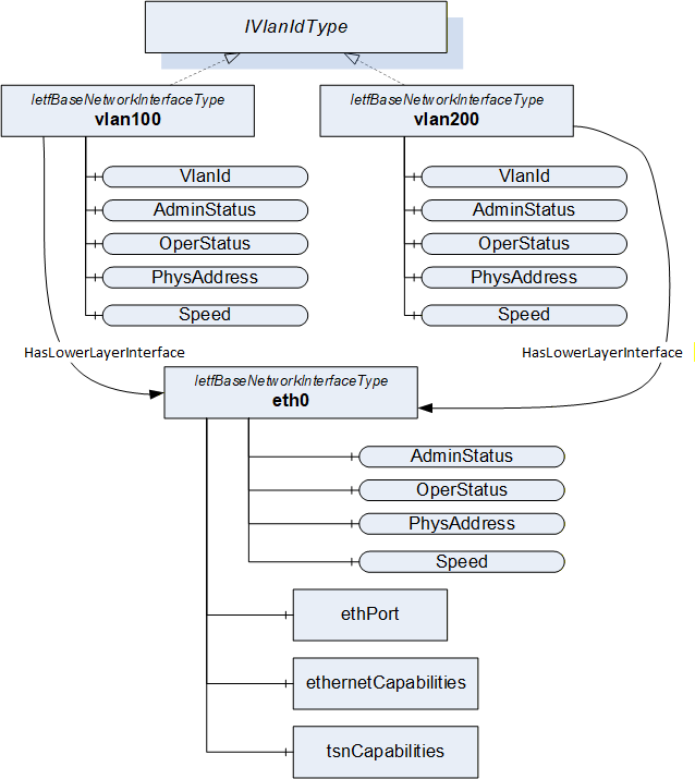
A.1.1 Virtual Network Interfaces
A virtual interfaces configuration can be represented by Objects representing the virtual and the physical network interface instances. HasLowerLayerInterface References point from the Object(s) representing the virtual interface(s) to the Object representing the physical interface. All Objects are of ObjectType IetfBaseNetworkInterfaceType. An example is shown in Figure A-1.
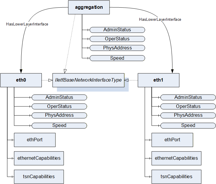
A.1.2 Link Aggregation
A link aggregation configuration can be represented by Objects representing the logical aggregation and the particular physical interface instances. HasLowerLayerInterface References point from the Object(s) representing the aggregation interface to the Objects representing the physical interfaces. All Objects implement the IIetfBaseNetworkInterfaceType. An example is shown in Figure A-2.
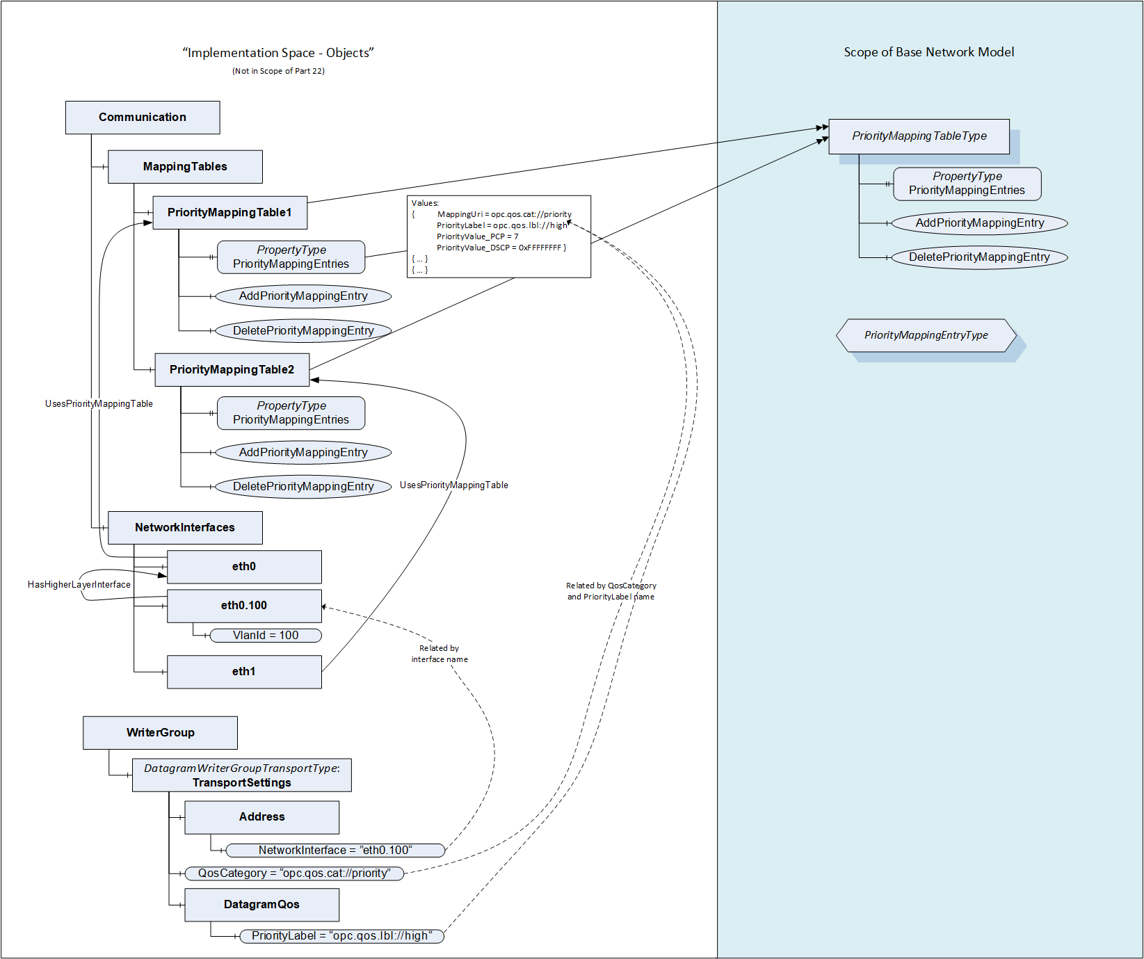
A.2 Modelling Examples for PriorityMappingEntries and IetfBaseNetworkInterface
All packets sent via this network interface will use the source address and - in case of VLAN interfaces - VLAN ID as specified by this interface to generate a packet. All packets received via this network interface will use - in case of unicast communication - the destination address and - in case of VLAN interfaces - VLAN ID as specified by the interface to filter incoming packets.
When using PubSub, each PubSubConnection as defined by the PubSubConnectionDataType in Part14 contains the address variable of type NetworkAddressDataType. If the networkInterface String of the NetworkAddressDataType matches the BrowseName of one Object in the NetworkInterfaces folder, it links the transmission or reception and the network interface. An example is shown in Figure A-3.
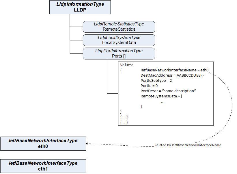
A.3 Connecting LldpPortInformationType and IetfBaseNetworkInterfaceType
The LldpPortInformationType is connected to the associated Object of type IetfBaseNetworkInterfaceType via the name of the variable IetfBaseNetworkInterfaceName. Figure A-4 shows an example of this reference for the IetfBaseNetworkInterface with the BrowseName eth0.
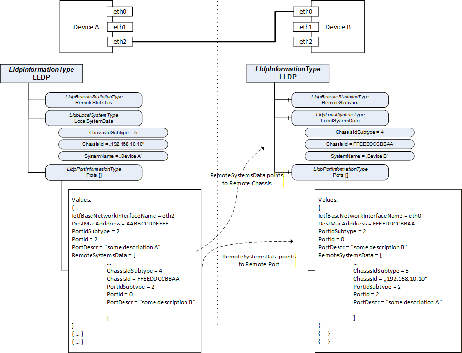
A.4 Topology Discovery with LldpRemoteSystems
LLDP exchanges information of the local system and its direct peers in the network through link-local communication. The local systems information of the peers is represented in the remote systems data structure. Figure A-5 shows an example for this connection between two different OPC UA Servers and their representation of the LLDP information. The RemoteSystemsData contains the information of the corresponding LocalSystemsData and PortInformation. For simplicity, this figure does not present all possible variables.
A.5 Usage of BNM in other UA Specifications
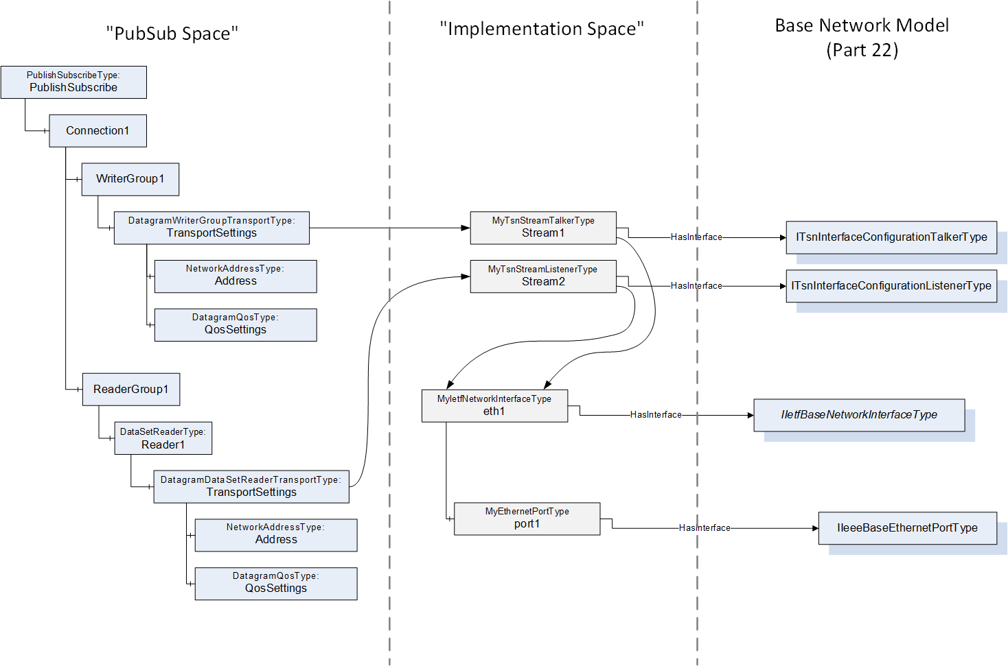
A.5.1 Usage of BNM for PubSub over TSN
An example using the BNM for PubSub over TSN is shown in Figure A-6.
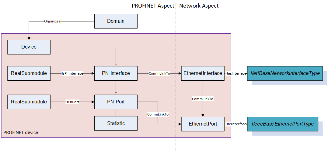
A.5.2 Usage of BNM in PROFINET Companion Spec
An example is shown in Figure A-7.
___________