
1 Scope
The OPC 40084 series provides OPC UA information models for extrusion. The different parts describe the extrusion line as a whole, and the different components. This part provides general types that are used for extrusion. Together with OPC 40083, which defines general type definitions for the complete sector plastics and rubber machinery, it is the basis for all other parts.
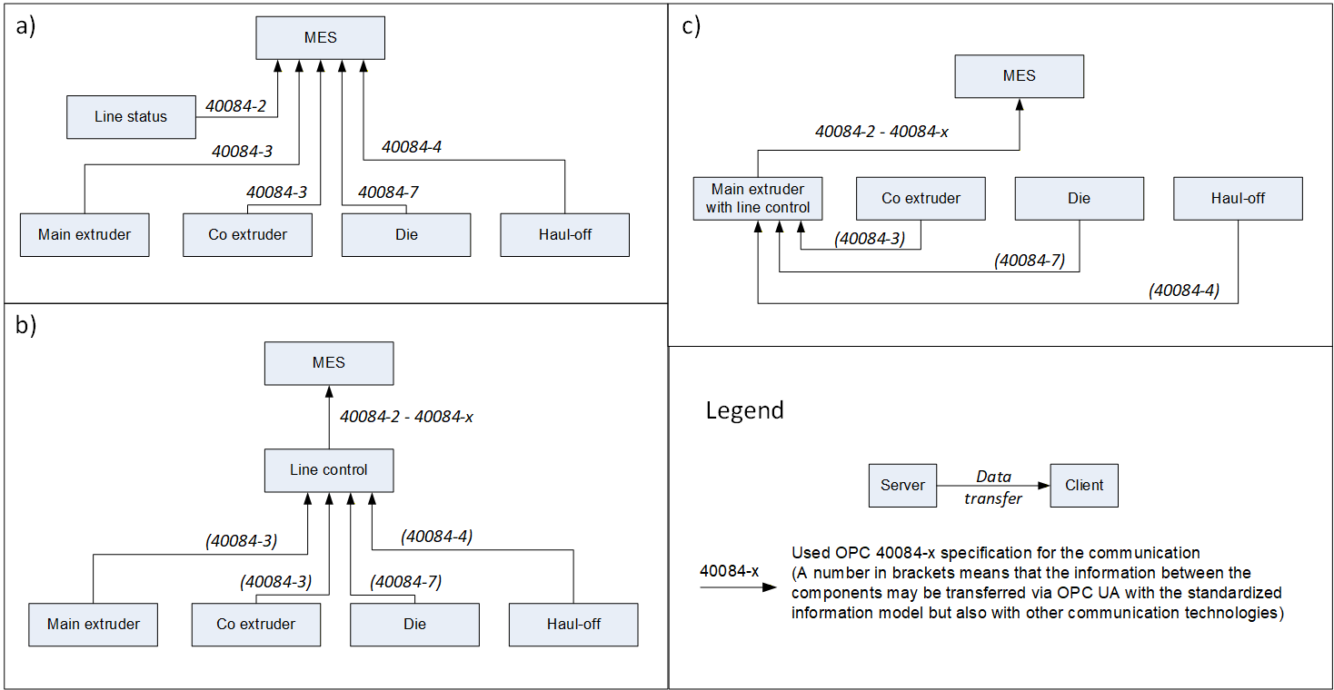
Different architectures are possible for the information flow between the components of an extrusion line and towards an MES. With the separated information models for the different components of an extrusion line three scenarios (and combinations of them) are possible:
Each component has an own OPC server and is connected directly to an MES
A line control collects all data from the components and forward these to the MES. The exchange between the line control and the components can be realised by OPC UA, but also by other technologies (e.g. field bus, EUROMAP 27)
The line control is included in an extruder
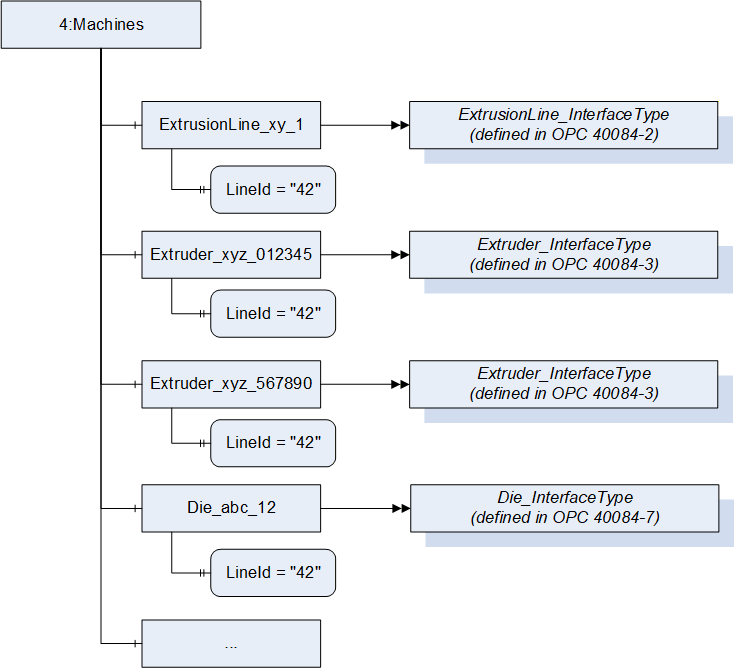
A server providing information for several components inside one extrusion line (here with the LineId "42") would have the following structure (example):
2 Normative references
The following documents are referred to in the text in such a way that some or all of their content constitutes requirements of this document. For dated references, only the edition cited applies. For undated references, the latest edition of the referenced document (including any amendments) applies
OPC 10000-1, OPC Unified Architecture - Part 1: Overview and Concepts
OPC 10000-1
OPC 10000-2, OPC Unified Architecture - Part 2: Security Model
OPC 10000-2
OPC 10000-3, OPC Unified Architecture - Part 3: Address Space Model
OPC 10000-3
OPC 10000-4, OPC Unified Architecture - Part 4: Services
OPC 10000-4
OPC 10000-5, OPC Unified Architecture - Part 5: Information Model
OPC 10000-5
OPC 10000-6, OPC Unified Architecture - Part 6: Mappings
OPC 10000-6
OPC 10000-7, OPC Unified Architecture - Part 7: Profiles
OPC 10000-7
OPC 10000-8, OPC Unified Architecture - Part 8: Data Access
OPC 10000-8
OPC 10000-16, OPC Unified Architecture - Part 16: State Machines
OPC 10000-16
OPC 10000-100, OPC Unified Architecture - Part 100: Devices
OPC 10000-100
OPC 40001-1, OPC UA for Machinery - Part 1: Basic Building Blocks
http://www.opcfoundation.org/UA/Machinery/
OPC 40083: OPC UA interfaces for plastics and rubber machinery - General Type definitions
http://www.opcfoundation.org/UA/PlasticsRubber/GeneralTypes
3 Terms, definitions and conventions
3.1 Overview
It is assumed that basic concepts of OPC UA information modelling are understood in this specification. This specification will use these concepts to describe the OPC 40084-1 Information Model. For the purposes of this document, the terms and definitions given in the documents referenced in Clause 2 apply.
3.2 Conventions used in this document
The conventions described in OPC 40083 apply.
4 General information to OPC UA interfaces for plastics and rubber machinery and OPC UA
For general information on OPC UA interfaces for plastics and rubber machinery and OPC UA see OPC 40083.
5 Use cases
OPC 40084-1 provides Object, Data and Variable Type definitions to be used in the following parts of the OPC 40084 series for extrusion. The intention is to create an interoperability between the different machines in an extrusion line.
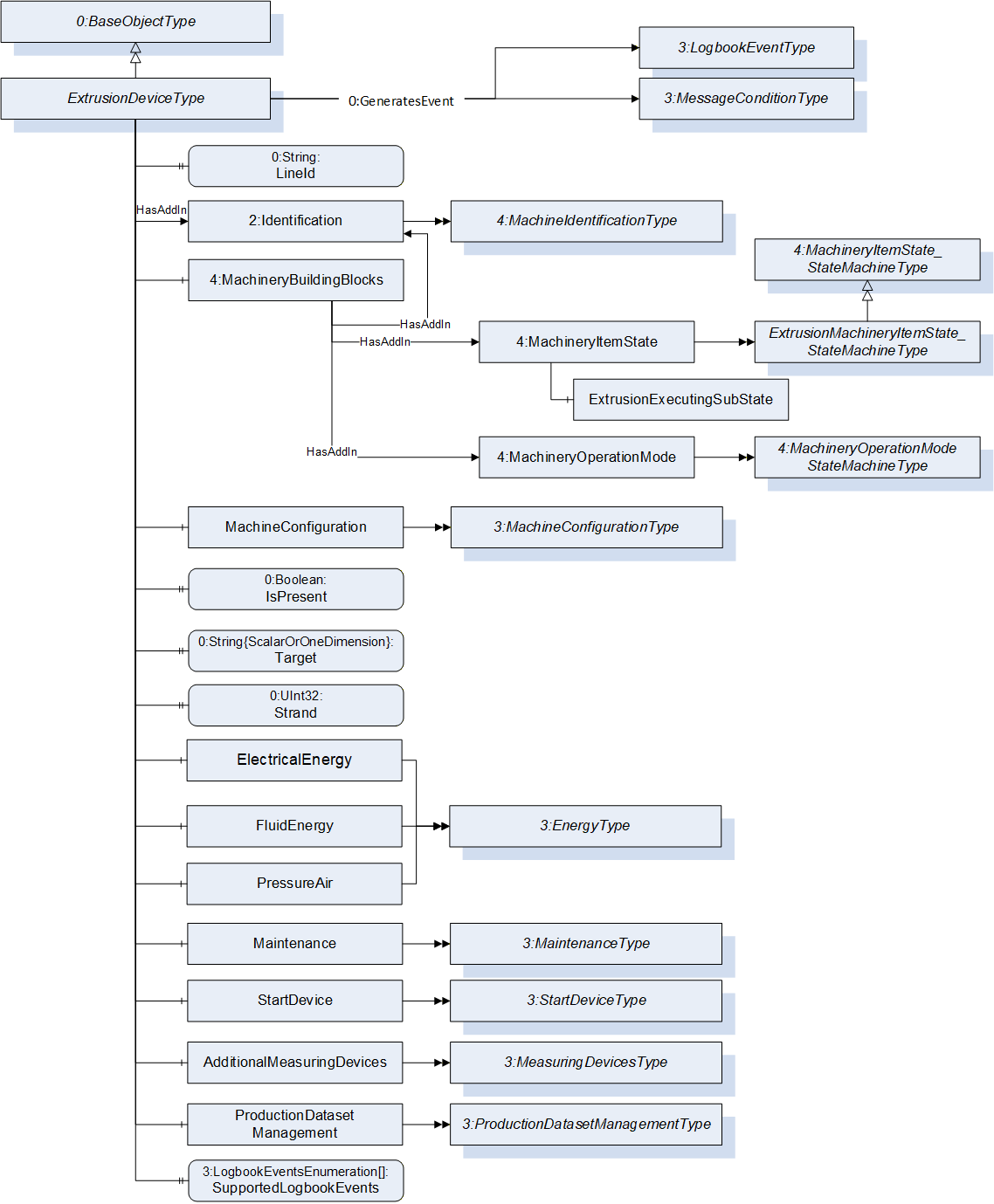
6 ExtrusionDeviceType
6.1 ExtrusionDeviceType Definition
This OPC UA ObjectType is used as base type for all components of an extrusion line (except the information model describing the extrusion line as a whole). This ObjectType is abstract, the different components of an extrusion line use derived Types with the necessary specific extensions.
| Attribute | Value | ||||
| BrowseName | ExtrusionDeviceType | ||||
| IsAbstract | True | ||||
| References | Node Class | BrowseName | DataType | TypeDefinition | Other |
|---|---|---|---|---|---|
| Subtype of 0:BaseObjectType defined in OPC 10000-5 | |||||
| 0:HasProperty | Variable | LineId | 0:String | 0:PropertyType | M, RW |
| 0:HasAddIn | Object | 2:Identification | 4:MachineIdentification Type | M | |
| 0:HasComponent | Object | 4:MachineryBuildingBlocks | 0:FolderType | M | |
| 0:HasComponent | Object | MachineConfiguration | 3:MachineConfiguration Type | O | |
| 0:HasProperty | Variable | IsPresent | 0:Boolean | 0:PropertyType | M, RO |
| 0:HasProperty | Variable | Target | 0:String{ScalarOrOneDimension} | 0:PropertyType | O, RO |
| 0:HasProperty | Variable | Strand | 0:UInt32 | 0:PropertyType | O, RO |
| 0:HasComponent | Object | ElectricalEnergy | 3:EnergyType | O | |
| 0:HasComponent | Object | FluidEnergy | 3:EnergyType | O | |
| 0:HasComponent | Object | PressureAir | 3:EnergyType | O | |
| 0:HasComponent | Object | Maintenance | 3:MaintenanceType | O | |
| 0:HasComponent | Object | StartDevice | 3:StartDeviceType | O | |
| 0:HasComponent | Object | AdditionalMeasuring Devices | 3:MeasuringDevicesType | O | |
| 0:HasComponent | Object | ProductionDataset Management | 3:ProductionDataset ManagementType | O | |
| 0:HasProperty | Variable | SupportedLogbookEvents | 3:LogbookEventsEnumeration[] | 0:PropertyType | M, RO |
| 0:GeneratesEvent | ObjectType | 3:MessageConditionType | Defined in OPC 40083 | ||
| 0:GeneratesEvent | ObjectType | 3:LogbookEventType | Defined in OPC 40083 | ||
| Conformance Units | |||||
|---|---|---|---|---|---|
| Extrusion Device |
6.2 LineId
This Property indicates to which extrusion line the extruder belongs to (e.g. "blown film line 2").
6.3 Identification and MachineryBuildingBlocks
The MachineIdentificationType is defined in OPC UA for Machinery (OPC 40001-1) and provides basic information on a machine/device.
For the InstanceDeclaration the ModellingRules of the Properties Model and DeviceClass are overridden to mandatory and the Property ControllerName is added.
The Object MachineryBuildingBlocks contains building blocks from OPC UA for Machinery as defined in OPC 40001-1. For this version of OPC 40084-1, the Object uses the two AddIns MachineryItemState and MachineryOperationMode, where for the first a sub-state machine with substates for Executing is added.
| BrowsePath | References | NodeClass | BrowseName | DataType | TypeDefinition | Other |
| 2:Identification | 0:HasProperty | Variable | 2:Model | 0:LocalizedText | 0:PropertyType | M, RO |
| 2:Identification | 0:HasProperty | Variable | 2:DeviceClass | 0:String | 0:PropertyType | M, RO |
| 2:Identification | 0:HasProperty | Variable | ControllerName | 0:String | 0:PropertyType | M, RO |
| 4:MachineryBuildingBlocks | 0:HasAddIn | Object | 2:Identification | 4:MachineIdentificationType | M | |
| 4:MachineryBuildingBlocks | 0:HasAddIn | Object | 4:MachineryItemState | ExtrusionMachineryItemState_StateMachineType | M | |
| 4:MachineryBuildingBlocks | 0:HasAddIn | Object | 4:MachineryOperationMode | 4:MachineryOperationModeStateMachineType | M |
The ControllerName Property represents the name of the machine controller (e.g. "CP22xx").
6.3.1 Extension of MachineryItemState
For this specification the MachineryItemState defined in OPC UA for Machinery is extended by a SubStateMachine for the State Executing.
For this, the ExtrusionMachineryItemState_StateMachineType is defined in Table 3.
| Attribute | Value | ||||
| BrowseName | ExtrusionMachineryItemState_StateMachineType | ||||
| IsAbstract | False | ||||
| References | Node Class | BrowseName | DataType | TypeDefinition | Other |
|---|---|---|---|---|---|
| Subtype of 4:MachineryItemState_StateMachineType defined in OPC UA for Machinery | |||||
| 0:HasProperty | Variable | 0:DefaultInstanceBrowseName | 0:QualifiedName | 0:PropertyType | |
| 0:HasComponent | Object | 4:NotAvailable | 0:StateType | ||
| 0:HasComponent | Object | 4:OutOfService | 0:StateType | ||
| 0:HasComponent | Object | 4:Executing | 0:StateType | ||
| 0:HasComponent | Object | 4:NotExecuting | 0:StateType | ||
| 0:HasComponent | Object | 4:FromNotAvailableToOutOfService | 0:TransitionType | ||
| 0:HasComponent | Object | 4:FromNotAvailableToNotExecuting | 0:TransitionType | ||
| 0:HasComponent | Object | 4:FromNotAvailableToExecuting | 0:TransitionType | ||
| 0:HasComponent | Object | 4:FromNotAvailableToNotAvailable | 0:TransitionType | ||
| 0:HasComponent | Object | 4:FromOutOfServiceToNotAvailable | 0:TransitionType | ||
| 0:HasComponent | Object | 4:FromOutOfServiceToNotExecuting | 0:TransitionType | ||
| 0:HasComponent | Object | 4:FromOutOfServiceToExecuting | 0:TransitionType | ||
| 0:HasComponent | Object | 4:FromOutOfServiceToOutOfService | 0:TransitionType | ||
| 0:HasComponent | Object | 4:FromNotExecutingToNotAvailable | 0:TransitionType | ||
| 0:HasComponent | Object | 4:FromNotExecutingToOutOfService | 0:TransitionType | ||
| 0:HasComponent | Object | 4:FromNotExecutingToExecuting | 0:TransitionType | ||
| 0:HasComponent | Object | 4:FromNotExecutingToNotExecuting | 0:TransitionType | ||
| 0:HasComponent | Object | 4:FromExecutingToNotAvailable | 0:TransitionType | ||
| 0:HasComponent | Object | 4:FromExecutingToOutOfService | 0:TransitionType | ||
| 0:HasComponent | Object | 4:FromExecutingToNotExecuting | 0:TransitionType | ||
| 0:HasComponent | Object | 4:FromExecutingToExecuting | 0:TransitionType | ||
| 0:HasComponent | Object | 4:ExtrusionExecutingSubState | ExtrusionExecutingSubState_StateMachineType | M | |
The InstanceDeclarations of the ExtrusionMachineryItemState_StateMachineType have additional Attribute values defined in Table 4
| BrowsePath | Value Attribute | Description Attribute | ||
| 0:DefaultInstanceBrowseName | MachineryItemState | The default BrowseName for instances of the type | ||
| 4:NotAvailable | The machine is not available and does not perform any activity (e.g., switched off, in energy saving mode) | |||
| 4:OutOfService | The machine is not functional and does not perform any activity (e.g., error, blocked) | |||
| 4:NotExecuting | The machine is available & functional and does not perform any activity. It waits for an action from outside to start or restart an activity | |||
| 4:Executing | The machine is available & functional and is actively performing an activity (pursues a purpose) | |||
| 4:FromNotAvailableToOutOfService | Transition from state NotAvailable to state OutOfService | |||
| 4:FromNotAvailableToNotExecuting | Transition from state NotAvailable to state NotExecuting | |||
| 4:FromNotAvailableToExecuting | Transition from state NotAvailable to state Executing | |||
| 4:FromNotAvailableToNotAvailable | Transition from state NotAvailable to state NotAvailable | |||
| 4:FromOutOfServiceToNotAvailable | Transition from state OutOfService to state NotAvailable | |||
| 4:FromOutOfServiceToNotExecuting | Transition from state OutOfService to state NotExecuting | |||
| 4:FromOutOfServiceToExecuting | Transition from state OutOfService to state Executing | |||
| 4:FromOutOfServiceToOutOfService | Transition from state OutOfService to state OutOfService | |||
| 4:FromNotExecutingToNotAvailable | Transition from state NotExecuting to state NotAvailable | |||
| 4:FromNotExecutingToOutOfService | Transition from state NotExecuting to state OutOfService | |||
| 4:FromNotExecutingToExecuting | Transition from state NotExecuting to state Executing | |||
| 4:FromNotExecutingToNotExecuting | Transition from state NotExecuting to state NotExecuting | |||
| 4:FromExecutingToNotAvailable | Transition from state Executing to state NotAvailable | |||
| 4:FromExecutingToOutOfService | Transition from state Executing to state OutOfService | |||
| 4:FromExecutingToNotExecuting | Transition from state Executing to state NotExecuting | |||
| 4:FromExecutingToExecuting | Transition from state Executing to state Executing | |||
| 0 | |||
| 1 | |||
| 2 | |||
| 3 | |||
| 0 | |||
| 1 | |||
| 2 | |||
| 3 | |||
| 4 | |||
| 5 | |||
| 6 | |||
| 7 | |||
| 8 | |||
| 9 | |||
| 10 | |||
| 11 | |||
| 12 | |||
| 13 | |||
| 14 | |||
| 15 |
The components of the ExtrusionMachineryItemState_StateMachineType have additional References which are defined in Table 5. As extension to the MachineryItemState_StateMachineType the State Executing gets an additional reference to the ExtrusionExecutingSubState.
| SourceBrowsePath | Reference Type | Is Forward | TargetBrowsePath |
| 4:FromNotAvailableToOutOfService | 0:FromState | True | 4:NotAvailable |
| 0:ToState | True | 4:OutOfService | |
| 4:FromNotAvailableToExecuting | 0:FromState | True | 4:NotAvailable |
| 0:ToState | True | 4:Executing | |
| 4:FromNotAvailableToNotExecuting | 0:FromState | True | 4:NotAvailable |
| 0:ToState | True | 4:NotExecuting | |
| 4:FromOutOfServiceToNotAvailable | 0:FromState | True | 4:OutOfService |
| 0:ToState | True | 4:NotAvailable | |
| 4:FromOutOfServiceToExecuting | 0:FromState | True | 4:OutOfService |
| 0:ToState | True | 4:Executing | |
| 4:FromOutOfServiceToNotExecuting | 0:FromState | True | 4:OutOfService |
| 0:ToState | True | 4:NotExecuting | |
| 4:FromExecutingToNotAvailable | 0:FromState | True | 4:Executing |
| 0:ToState | True | 4:NotAvailable | |
| 4:FromExecutingToOutOfService | 0:FromState | True | 4:Executing |
| 0:ToState | True | 4:OutOfService | |
| 4:FromExecutingToNotExecuting | 0:FromState | True | 4:Executing |
| 0:ToState | True | 4:NotExecuting | |
| 4:FromNotExecutingToNotAvailable | 0:FromState | True | 4:NotExecuting |
| 0:ToState | True | 4:NotAvailable | |
| 4:FromNotExecutingToOutOfService | 0:FromState | True | 4:NotExecuting |
| 0:ToState | True | 4:OutOfService | |
| 4:FromNotExecutingToExecuting | 0:FromState | True | 4:NotExecuting |
| 0:ToState | True | 4:Executing | |
| 4:FromNotAvailableToNotAvailable | 0:FromState | True | 4:NotAvailable |
| 0:ToState | True | 4:NotAvailable | |
| 4:FromOutOfServiceToOutOfService | 0:FromState | True | 4:OutOfService |
| 0:ToState | True | 4:OutOfService | |
| 4:FromExecutingToExecuting | 0:FromState | True | 4:Executing |
| 0:ToState | True | 4:Executing | |
| 4:FromNotExecutingToNotExecuting | 0:FromState | True | 4:NotExecuting |
| 0:ToState | True | 4:NotExecuting | |
| 4:Executing | 0:HasSubStateMachine | True | ExtrusionExecutingSubState |
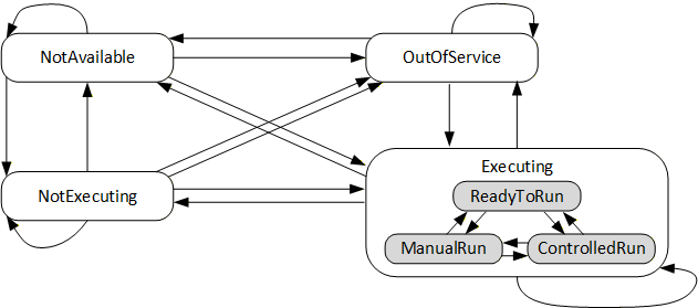
6.3.2 Definition of ExtrusionExecutingSubState_StateMachineType
The ExtrusionExecutingSubState_StateMachineType is used for a SubStateMachine which divides the Executing State into ReadyToRun, ManualRun and ControlledRun. This SubStateMachine is not active if the parent State Executing is not active. In this case the CurrentState and LastTransition Variables of the ExtrusionExecutingSubState state machine shall have a status equal to Bad_StateNotActive.
| Attribute | Value | ||||
| BrowseName | ExtrusionExecutingSubState_StateMachineType | ||||
| IsAbstract | False | ||||
| References | Node Class | BrowseName | DataType | TypeDefinition | Other |
|---|---|---|---|---|---|
| Subtype of the 0:FiniteStateMachineType defined in OPC 10000-16, i.e. inheriting the InstanceDeclarations of that Node. | |||||
| 0:HasComponent | Object | ReadyToRun | 0:StateType | ||
| 0:HasComponent | Object | ManualRun | 0:StateType | ||
| 0:HasComponent | Object | ControlledRun | 0:StateType | ||
| 0:HasComponent | Object | FromReadyToRunToManualRun | 0:TransitionType | ||
| 0:HasComponent | Object | FromManualRunToReadyToRun | 0:TransitionType | ||
| 0:HasComponent | Object | FromReadyToRunToControlledRun | 0:TransitionType | ||
| 0:HasComponent | Object | FromControlledRunToReadyToRun | 0:TransitionType | ||
| 0:HasComponent | Object | FromManualRunToControlledRun | 0:TransitionType | ||
| 0:HasComponent | Object | FromControlledRunToManualRun | 0:TransitionType | ||
| Conformance Units | |||||
|---|---|---|---|---|---|
| Extrusion Device |
The difference between NotExecuting and ReadyToRun is that in he state NotExecuting also the heating is switched off and in the state ReadyToRun it is switched on (but no movement of the screw).
The InstanceDeclaration of the ExtrusionExecutionSubState_StateMachineType has additional Attribute values defined in Table 7.
| SourceBrowsePath | Value | Description | ||
| ReadyToRun | Component is not running but able to start immediately (e.g. heating is switched on, set temperatures have been reached) | |||
| ManualRun | Component is running with manually set parameters | |||
| ControlledRun | Component is running with controlled parameters | |||
| FromReadyToRunToManualRun | Transition from state ReadyToRun to state ManualRun | |||
| FromManualRunToReadyToRun | Transition from state ManualRun to state ReadyToRun | |||
| FromReadyToRunToControlledRun | Transition from state ReadyToRun to state ControlledRun | |||
| FromControlledRunToReadyToRun | Transition from state ControlledRun to state ReadyToRun | |||
| FromManualRunToControlledRun | Transition from state ManualRun to state ControlledRun | |||
| FromControlledRunToManualRun | Transition from state ControlledRun to state ManualRun | |||
| 0 | |||
| 1 | |||
| 2 | |||
| 0 | |||
| 1 | |||
| 2 | |||
| 3 | |||
| 4 | |||
| 5 |
The components of the ExtrusionExecutingSubState_StateMachineType have additional References which are defined in Table 8.
| SourceBrowsePath | Reference Type | Is Forward | TargetBrowsePath |
| FromReadyToRunToManualRun | 0:FromState | True | ReadyToRun |
| 0:ToState | True | ManualRun | |
| FromManualRunToReadyToRun | 0:FromState | True | ManualRun |
| 0:ToState | True | ReadyToRun | |
| FromReadyToRunToControlledRun | 0:FromState | True | ReadyToRun |
| 0:ToState | True | ControlledRun | |
| FromControlledRunToReadyToRun | 0:FromState | True | ControlledRun |
| 0:ToState | True | ReadyToRun | |
| FromManualRunToControlledRun | 0:FromState | True | ManualRun |
| 0:ToState | True | ControlledRun | |
| FromControlledRunToManualRun | 0:FromState | True | ControlledRun |
| 0:ToState | True | ManualRun |
6.4 MachineConfiguration
The MachineConfigurationType is defined in OPC 40083 and provides information on the current configuration of a machine/device.
6.5 IsPresent
The IsPresent Property provides information if the component is physically installed and connected.
6.6 Target
This Property informs where the material/melt from this device goes to (e.g. the target of an extruder can be a die, but also a melt-pump). The value shall be equal to the value of the Property UserMachineName inside the MachineConfiguration Object of the relevant component.
Note: Using the NodeId of the device not possible because the components may have different servers. In this case the NodeIds are not unique in the complete extrusion line. It is also possible to fill a descriptive String in the Target property if the target component has no OPC UA representation.
6.7 Strand
Strand is used when several products (two pipes is parallel, foil cut into several smaller foils) are produced in parallel. It is only used for a component, which can be unambiguously assigned to one of the products.
6.8 ElectricalEnergy
Electrical energy of the component. The EnergyType is defined in OPC 40083.
6.9 FluidEnergy
Energy for the cooling of the component with fluid. The EnergyType is defined in OPC 40083.
6.10 PressureAir
Consumption of pressure air of the component (volume at standard conditions). The EnergyType is defined in OPC 40083.
6.11 Maintenance
The MaintenanceType is defined in OPC 40083.
6.12 StartDevice
This Object is used to give information on the starting status of a device and optional to switch devices on and off via the interface. The StartDeviceType is defined in OPC 40083.
6.13 AdditionalMeasuringDevices
This Objects is a container for possible additional measuring devices used in the component. The MeasuringDevicesType is defined in OPC 40083.
6.14 ProductionDatasetManagement
The ProductionDatasetManagementType is defined in OPC 40083 and provides functionalities for the management of recipes/machine settings.
6.15 SupportedLogbookEvents
This list of LogbookEventsEnumeration gives information which LogbookEvents are supported by the machine. The LogbookEventsEnumeration is defined in OPC 40083.
6.16 Events
A Component may generate Events of MessageConditionType and LogbookEventType (see OPC 40083).
7 ExtrusionMessageClassificationEnumeration
This Enumeration specifies the values to be used in the Classification property in the MessageConditionType and related logbook events to indicate which machine part has caused the message. These events are fired by the instance of the ExtrusionDeviceType and are defined in OPC 40083.
| Name | Value | Description |
| OTHER | 0 | This value is used if none of the other entries below apply. |
| LINE_CONTROL | 1 | Line control |
| MATERIAL_HANDLING | 2 | Material handling (from silo to processing machine) |
| PRE_HEATING | 3 | Pre-heating, drying of input material |
| FEEDING | 4 | Feeding unit |
| DOSING | 5 | Dosing unit |
| EXTRUDER | 6 | Extruder |
| VACUUM_STATION | 7 | Vacuum station |
| FILTER | 8 | Filter |
| MELT_PUMP | 9 | Melt pump |
| DIE | 10 | Profile die, pipe die, … |
| COOLING | 11 | Cooling |
| HAUL_OFF | 12 | Haul-off |
| CORRUGATOR | 13 | Corrugator |
| SAW | 14 | Saw |
| CALIBRATION | 15 | Calibration |
| ROLL_STACK | 16 | Roll stack |
| MDO | 17 | Machine direction orientation |
| BIAX | 18 | Biaxial orientation |
| CUTTING | 19 | Cutting |
| WINDER | 20 | Winder |
| PELLETIZING | 21 | Pelletizing |
| DRYER | 22 | Drying of product/output material (e.g. after underwater cutting) |
| HANDLING_SYSTEM | 23 | Handling system for produced products (e.g. robot stacking profiles) |
| LAMINATION_SYSTEM | 24 | Lamination system |
| MEASURING_SYSTEM | 25 | Measuring System (e.g. thickness measurement) |
| QUALITY_SYSTEM | 26 | Quality system (e.g. camera inspection) |
| MANUAL_INSPECTION | 27 | Manual inspection (message generated due to quality input by the operator) |
| MANUAL_OPERATION | 28 | Manual operation (message generated due to action of the operator, e.g. changing of machine mode) |
8 TemperatureZones
8.1 ExtrusionTemperatureZonesType
This ObjectType is a container for temperature zones inside of a component of an extrusion line. It is formally defined in Table 10.
| Attribute | Value | ||||
| BrowseName | ExtrusionTemperatureZonesType | ||||
| IsAbstract | False | ||||
| References | Node Class | BrowseName | DataType | TypeDefinition | Other |
|---|---|---|---|---|---|
| Subtype of 0:BaseObjectType defined in OPC 10000-5 | |||||
| 0:HasProperty | Variable | 0:NodeVersion | 0:String | 0:PropertyType | M, RO |
| 0:HasComponent | Object | StartTempering | 3:StartDeviceType | O | |
| 0:HasComponent | Object | Maintenance | 3:MaintenanceType | O | |
| 0:HasComponent | Object | TemperatureZone_<Nr> | ExtrusionTemperature ZoneType | OP | |
| 0:GeneratesEvent | ObjectType | 0:GeneralModelChange EventType | |||
When instances for temperature zones are created, the BrowseNames shall be "TemperatureZone_<Nr>" where <Nr> is a three-digit number with leading zeros, starting with "001". The ExtrusionTemperatureZoneType is defined in Table 11.
StartTempering: Main switch for all temperature zones in the container. The single zones have own switches/status AND-connection!
8.2 ExtrusionTemperatureZoneType
This ObjectType represents one temperature zone inside of a component of an extrusion line. It is formally defined in Table 11.
| Attribute | Value | ||||
| BrowseName | ExtrusionTemperatureZoneType | ||||
| IsAbstract | False | ||||
| References | Node Class | BrowseName | DataType | TypeDefinition | Other |
|---|---|---|---|---|---|
| Subtype of 3:MeasuringDeviceType defined in OPC 40083 | |||||
| 0:HasComponent | Variable | NominalHeatingPower | 0:Double | 0:AnalogUnitType | O, RO |
| 0:HasComponent | Variable | NominalCoolingPower | 0:Double | 0:AnalogUnitType | O, RO |
| 0:HasComponent | Variable | ControllerOutput | 0:Double | 0:AnalogUnitType | O, RO |
| 0:HasComponent | Object | ElectricalCurrent | 3:MonitoredParameterType | O | |
8.2.1 NominalHeatingPower
Indication of the nominal heating power of the zone in kW. If the zone is only a cooling zone, this variable is not used.
8.2.2 NominalCoolingPower
Indication of the nominal cooling power of the zone in kW. If the zone is only a heating zone, this variable is not used.
8.2.3 ControllerOutput
Actual ratio of the used nominal power in %. Values from -100 (=max. cooling) to +100 (max. heating).
8.2.4 ElectricalCurrent
Actual electrical current of the zone in A.
9 Rolls and Gaps
Several machines in an extrusion lines (e.g. calenders) contain rolls and gaps between rolls.
9.1 RollsType
The RollsType defines a container for several rolls inside of a component of an extrusion line. It is formally defined in Table 12.
| Attribute | Value | ||||
| BrowseName | RollsType | ||||
| IsAbstract | False | ||||
| References | Node Class | BrowseName | DataType | TypeDefinition | Other |
|---|---|---|---|---|---|
| Subtype of the 0:BaseObjectType defined in OPC 10000-5 | |||||
| 0:HasProperty | Variable | 0:NodeVersion | 0:String | 0:PropertyType | M, RO |
| 0:HasComponent | Object | Roll_<Nr> | RollType | OP | |
| 0:GeneratesEvent | ObjectType | 0:GeneralModelChangeEventType | |||
9.2 RollType
The RollType described a single roll. It is formally defined in Table 13.
| Attribute | Value | ||||
| BrowseName | RollType | ||||
| IsAbstract | False | ||||
| References | Node Class | BrowseName | DataType | TypeDefinition | Other |
|---|---|---|---|---|---|
| Subtype of the 0:BaseObjectType defined in OPC 10000-5 | |||||
| 0:HasProperty | Variable | Id | 0:String | 0:PropertyType | M, RO |
| 0:HasProperty | Variable | Name | 0:LocalizedText | 0:PropertyType | O, RO |
| 0:HasProperty | Variable | MasterRollId | 0:String | 0:PropertyType | O, RO |
| 0:HasComponent | Object | Drive | 3:DriveType | M | |
| 0:HasComponent | Object | Temperature | ExtrusionTemperatureZoneType | O | |
| 0:HasComponent | Object | CrossAxisLeft | 3:MonitoredParameterType | O | |
| 0:HasComponent | Object | CrossAxisRight | 3:MonitoredParameterType | O | |
| 0:HasComponent | Object | PeripheralDevices | RollPeripheralDevicesType | O | |
| 0:HasComponent | Object | RollBending | RollBendingType | O | |
9.2.1 Id
Id of the roll
9.2.2 Name
(Human readable) name of the roll
9.2.3 MasterRollId
Id of the master roll. If a roll is the master roll then MasterRollId = Id.
9.2.4 Drive
Information about the drive of the roll. The DriveType is defined in OPC 40083.
9.2.5 Temperature
Temperature of the roll.
9.2.6 CrossAxisLeft, CrossAxisRight
Axis crossing of the roll on both sides (in the direction of the material flow). The MonitoredParameterType is defined in OPC 40083.
Unit: mm or inch
9.2.7 RollPeripheralDevices
A roll can be equipped with infrared heating systems and/or cleaning systems. Their representations are put into the container RollPeripheralDevices. The RollPeripheralDevicesType is formally defined in Table 14.
| Attribute | Value | ||||
| BrowseName | RollPeripheralDevicesType | ||||
| IsAbstract | False | ||||
| References | Node Class | BrowseName | DataType | TypeDefinition | Other |
|---|---|---|---|---|---|
| Subtype of the 0:BaseObjectType defined in OPC 10000-5 | |||||
| 0:HasProperty | Variable | 0:NodeVersion | 0:String | 0:PropertyType | M, RO |
| 0:HasComponent | Object | InfraredHeatingSystem_<Nr> | 3:StartDeviceType | OP | |
| 0:HasComponent | Object | CleaningSystem_<Nr> | 3:StartDeviceType | OP | |
| 0:GeneratesEvent | ObjectType | 0:GeneralModelChangeEventType | |||
The StartDeviceType usesd for the infrared heating systems and cleaning systems is defined in OPC 40083.
9.2.8 RollBending
If roll bending is used, the monitoring of the positions of the reference points are described with the RollBendingType. It is formally defined in Table 15.
| Attribute | Value | ||||
| BrowseName | RollBendingType | ||||
| IsAbstract | False | ||||
| References | Node Class | BrowseName | DataType | TypeDefinition | Other |
|---|---|---|---|---|---|
| Subtype of the 0:BaseObjectType defined in OPC 10000-5 | |||||
| 0:HasProperty | Variable | 0:NodeVersion | 0:String | 0:PropertyType | M, RO |
| 0:HasComponent | Object | ReferencePoint_<Nr> | 3:MeasuringDeviceType | OP | |
| 0:GeneratesEvent | ObjectType | 0:GeneralModelChangeEventType | |||
9.3 GapsType
The GapsType defines a container for several gaps between two rolls (e.g. of a calender). It is formally defined in Table 16.
| Attribute | Value | ||||
| BrowseName | GapsType | ||||
| IsAbstract | False | ||||
| References | Node Class | BrowseName | DataType | TypeDefinition | Other |
|---|---|---|---|---|---|
| Subtype of the 0:BaseObjectType defined in OPC 10000-5 | |||||
| 0:HasProperty | Variable | 0:NodeVersion | 0:String | 0:PropertyType | M, RO |
| 0:HasComponent | Object | Gap_<Nr> | GapType | OP | |
| 0:GeneratesEvent | ObjectType | 0:GeneralModelChangeEventType | |||
9.4 GapType
The GapType described a gap between two rolls. It is formally defined in Table 17.
| Attribute | Value | ||||
| BrowseName | GapType | ||||
| IsAbstract | False | ||||
| References | Node Class | BrowseName | DataType | TypeDefinition | Other |
|---|---|---|---|---|---|
| Subtype of the 0:BaseObjectType defined in OPC 10000-5 | |||||
| 0:HasProperty | Variable | Id | 0:String | 0:PropertyType | M, RO |
| 0:HasProperty | Variable | RollId1 | 0:String | 0:PropertyType | M, RO |
| 0:HasProperty | Variable | RollId2 | 0:String | 0:PropertyType | M, RO |
| 0:HasComponent | Object | DistanceLeft | 3:MonitoredParameterType | O | |
| 0:HasComponent | Object | DistanceRight | 3:MonitoredParameterType | O | |
| 0:HasComponent | Variable | IsClosed | 0:Boolean | 0:BaseDataVariableType | O, RO |
| 0:HasComponent | Object | ContactForce | 0:Double | 3:MonitoredParameterType | O, RO |
| 0:HasProperty | Variable | StockingGuideIsPresent | 0:Boolean | 0:PropertyType | O, RO |
9.4.1 Id
Id of the gap.
9.4.2 RollId1, RollId2
Ids of the rolls which create the gap.
9.4.3 DistanceLeft, DistanceRight
Distances between the rolls on both sides (in the direction of the material flow). The MonitoredParameterType is defined in OPC 40083.
Unit: mm or inch
9.4.4 IsClosed
True, when the rolls forming the gaps are in working position.
9.4.5 ContactForce
Contact force between the rolls (mainly measured indirectly via the fluid pressure). The MonitoredParameterType is defined in OPC 40083.
Unit: N or lfb
9.4.6 StockingGuideIsPresent
Information if a stocking guide is present.
10 Profiles and Conformance Units
10.1 Conformance Units
This chapter defines the corresponding Conformance Units for OPC 40084-1.
| Category | Title | Description |
| Server | Extrusion Device | Supports the ExtrusionDeviceType with all its mandatory InstanceDeclarations. There is at least one instance of the ExtrusionDeviceType or a subtype representing a machine/component of an extrusion line. |
| Server | Extrusion Production Dataset Management | Supports the 3:ProductionDatasetManagementType (defined in OPC 40083) with all its mandatory InstanceDeclarations. There is the component ProductionDatasetManagement available in the instance of the ExtrusionDeviceType or a subtype representing a machine/component of an extrusion line. |
10.2 Profiles
10.2.1 Profile list
Table 19 lists all Profiles defined in this document and defines their URIs.
| Profile | URI |
| Extrusion v2 Extrusion Device Basic Server Profile | http://opcfoundation.org/UA-Profile/PlasticsRubber/Extrusion_v2/ExtrusionDeviceBasic |
| Extrusion v2 Production Dataset Management Server Facet | http://opcfoundation.org/UA-Profile/PlasticsRubber/Extrusion_v2/ProductionDatasetManagement |
10.2.2 Server Facets
10.2.2.1 Overview
The following sections specify the Facets available for Servers that implement the OPC 40084-1 companion specification. Each section defines and describes a Facet or Profile.
10.2.2.2 Extrusion Device Basic Server Profile
Table 20 defines a Profile that provides the basic functionalities of an device in an extrusion line managed in an OPC UA Server.
| Group | Conformance Unit / Profile Title | Mandatory / Optional |
| Server | 0:Embedded Server 2017 (defined in OPC 10000-7) | M |
| Server | 0:ComplexType Server Facet (defined in OPC 10000-7) | M |
| Server | 0:Standard Event Subscription Server Facet (defined in OPC 10000-7) | M |
| Server | 0:Method Server Facet (defined in OPC 10000-7) | M |
| Server | 2:BaseDevice Server Facet (defined in OPC 10000-100) | M |
| Security | 0:SecurityPolicy [B] - Basic256Sha256 | M |
| Extrusion | Extrusion Device | M |
10.2.2.3 Extrusion v2 Production Dataset Management Server Facet
Table 21 defines a Facet that provides the ProductionDatasetManagement Object in the OPC UA Server.
| Group | Conformance Unit / Profile Title | Mandatory / Optional |
| Extrusion | Extrusion Production Dataset Management | M |
10.2.3 Client Facets
This version of the specification does not define any Client Facets.
11 Namespaces
11.1 Namespace Metadata
Table 22 defines the namespace metadata for this specification. The Object is used to provide version information for the namespace and an indication about static Nodes. Static Nodes are identical for all Attributes in all Servers, including the Value Attribute. See OPC 10000-5 for more details.
The information is provided as Object of type NamespaceMetadataType. This Object is a component of the Namespaces Object that is part of the Server Object. The NamespaceMetadataType ObjectType and its Properties are defined in OPC 10000-5.
The version information is also provided as part of the ModelTableEntry in the UANodeSet XML file. The UANodeSet XML schema is defined in OPC 10000-6.
| Attribute | Value | ||
| BrowseName | http://opcfoundation.org/UA/PlasticsRubber/Extrusion_v2/GeneralTypes/ | ||
| Property | DataType | Value | |
|---|---|---|---|
| NamespaceUri | String | http://opcfoundation.org/UA/PlasticsRubber/Extrusion_v2/GeneralTypes/ | |
| NamespaceVersion | String | 2.00 | |
| NamespacePublicationDate | DateTime | 2022-05-01 | |
| IsNamespaceSubset | Boolean | False | |
| StaticNodeIdTypes | IdType[] | 0 | |
| StaticNumericNodeIdRange | NumericRange[] | ||
| StaticStringNodeIdPattern | String | ||
11.2 Handling of OPC UA Namespaces
Namespaces are used by OPC UA to create unique identifiers across different naming authorities. The Attributes NodeId and BrowseName are identifiers. A Node in the UA AddressSpace is unambiguously identified using a NodeId. Unlike NodeIds, the BrowseName cannot be used to unambiguously identify a Node. Different Nodes may have the same BrowseName. They are used to build a browse path between two Nodes or to define a standard Property.
Servers may often choose to use the same namespace for the NodeId and the BrowseName. However, if they want to provide a standard Property, its BrowseName shall have the namespace of the standards body although the namespace of the NodeId reflects something else, for example the EngineeringUnits Property. All NodeIds of Nodes not defined in this document shall not use the standard namespaces.
Table 23 provides a list of mandatory and optional namespaces used in an OPC 40084-1 OPC UA Server.
| NamespaceURI | Description | Use |
| http://opcfoundation.org/UA/ | Namespace for NodeIds and BrowseNames defined in the OPC UA specification. This namespace shall have namespace index 0. | Mandatory |
| Local Server URI | Namespace for nodes defined in the local server. This may include types and instances used in a device represented by the server. This namespace shall have namespace index 1. | Mandatory |
| http://opcfoundation.org/UA/DI/ | Namespace for NodeIds and BrowseNames defined in OPC 10000-100. The namespace index is server specific. | Mandatory |
http://opcfoundation.org/UA/PlasticsRubber/ GeneralTypes/ | Namespace for NodeIds and BrowseNames defined in OPC 40083. The namespace index is server specific. | Mandatory |
| http://opcfoundation.org/UA/Machinery/ | Namespace for NodeIds and BrowseNames defined in OPC 40001-1. The namespace index is server specific. | Mandatory |
http://opcfoundation.org/UA/PlasticsRubber/ Extrusion_v2/GeneralTypes/ | Namespace for NodeIds and BrowseNames defined in this specification. The namespace index is server specific. | Mandatory |
| Vendor specific types and instances | A server may provide vendor specific types like types derived from MachineType or MachineStatusType or vendor specific instances of devices in a vendor specific namespace. | Optional |
Table 24 provides a list of namespaces and their index used for BrowseNames in this specification. The default namespace of this specification is not listed since all BrowseNames without prefix use this default namespace.
| NamespaceURI | Namespace Index | Example |
| http://opcfoundation.org/UA/ | 0 | 0:NodeVersion |
| http://opcfoundation.org/UA/DI/ | 2 | 2:DeviceClass |
| http://opcfoundation.org/UA/PlasticsRubber/GeneralTypes/ | 3 | 3:EnergyType |
| http://opcfoundation.org/UA/Machinery/ | 4 | 4:MachineIdentificationType |
Annex A OPC 40084-1 Namespace and mappings (Normative)
A.1 Namespace and identifiers for OPC 40084-1 Information Model
This appendix defines the numeric identifiers for all of the numeric NodeIds defined in this specification. The identifiers are specified in a CSV file with the following syntax:
<SymbolName>, <Identifier>, <NodeClass>Where the SymbolName is either the BrowseName of a Type Node or the BrowsePath for an Instance Node that appears in the specification and the Identifier is the numeric value for the NodeId.
The BrowsePath for an Instance Node is constructed by appending the BrowseName of the instance Node to the BrowseName for the containing instance or type. An underscore character is used to separate each BrowseName in the path. Let's take for example, the MachineInformationType ObjectType Node which has the ControllerName Property. The Name for the ControllerName InstanceDeclaration within the MachineInformationType declaration is: MachineInformationType_ControllerName.
The NamespaceUri for all NodeIds defined here is http://opcfoundation.org/UA/PlasticsRubber/Extrusion_v2/GeneralTypes/
The CSV released with this version of the specification can be found here:
http://www.opcfoundation.org/UA/schemas/PlasticsRubber/Extrusion_v2/GeneralTypes/2.00/NodeIds.csv
http://www.opcfoundation.org/UA/schemas/PlasticsRubber/Extrusion_v2/GeneralTypes/NodeIds.csv
A computer processible version of the complete Information Model defined in this specification is also provided. It follows the XML Information Model schema syntax defined in Part 6.
The Information Model Schema released with this version of the specification can be found here:
Annex B Mapping from version 1.01 to 2.00 (Informative)
B.1 Identification
In the ExtrusionDeviceType, the Object MachineInformation (MachineInformationType from OPC 40083) has been replaced by Identification (MachineIdentificationType from OPC 40001-1).
| Version 1.01 MachineInformation | Version 2.00 Identification | ||
| Inherited from ComponentType | |||
| Applied from IVendorNameplateType | Applied from IVendorNameplateType | ||
| Manufacturer | mandatory (override in MachineInformationType) | Manufacturer | mandatory |
| ManufacturerUri | optional | ManufacturerUri | optional |
| Model | mandatory (override in MachineInformationType) | Model | mandatory (override in instance declaration of Identification Object in ExtrusionDeviceType ) |
| ProductCode | optional | ProductCode | optional |
| HardwareRevision | optional | HardwareRevision | optional |
| SoftwareRevision | optional | SoftwareRevision | optional |
| DeviceRevision | optional | Not applied in MachineIdentificationType | |
| DeviceManual | optional | Not applied in MachineIdentificationType | |
| DeviceClass | mandatory (override in MachineInformationType) | DeviceClass | mandatory (override in instance declaration of Identification Object in ExtrusionDeviceType ) |
| SerialNumber | mandatory (override in MachineInformationType) | SerialNumber | mandatory |
| ProductInstanceUri | optional | ProductInstanceUri | mandatory |
| RevisionCounter | optional | Not applied in MachineIdentificationType | |
| Applied from ITagNameplateType | Applied from ITagNameplateType | ||
|---|---|---|---|
| AssetId | optional | AssetId | optional |
| ComponentName | optional | ComponentName | optional |
| Added in MachineInformationType (OPC 40083) | |||
|---|---|---|---|
| ControllerName | mandatory | ControllerName | Added in instance declaration of Identification Object in ExtrusionDeviceType |
| SupportedLogbookEvents | mandatory | SupportedLogbookEvents | Addid in ExtrusionDeviceType |
|
Additional
Properties
from
IMachineryItem
VendorNameplateType | |||
|---|---|---|---|
| No matching Property in v 1.01 | YearOfConstruction | optional | |
| No matching Property in v 1.01 | MonthOfConstruction | optional | |
| No matching Property in v 1.01 | InitialOperationDate | optional | |
| Additional Property from IMachineTagNameplateType | |||
|---|---|---|---|
| LocationName in MachineConfiguration | Location | optional | |
B.2 Status
In the ExtrusionDeviceType, the Variable Status has been replaced by the two state machines MachineryItemState and MachineryOperationMode (see OPC 40001-1). The state machine MachineryItemState is extended by a sub state machine ExtrusionExecutingSubState.
As the status information is now split into two states, there is no one-to-one relation between the old states in version 1.01 and the new ones in version 2.0. For example, MALFUNCTION and MAINTENANCE which are separate states in version 1.01 can occur at the same time with the MachineryItemState OutOfService and MachineryOperationMode Maintenance when there is an error during maintenance.
|
Version 1.01
ExtrusionDeviceType Status | Version 2.00 Identification | ||
| Name | Value | MachineryItemState | MachineryOperationMode |
| OFFLINE | 0 | NotAvailable | any |
| IDLE | 1 | NotExecuting | any |
| PREPARING | 2 | Executing (with any substate) | Setup |
| READY_TO_RUN | 3 | Executing with sub state ReadyToRun | Processing |
| MANUAL_RUN | 4 | Executing with sub state ManualRun | Processing |
| CONTROLLED_RUN | 5 | Executing with sub state ControlledRun | Processing |
| MALFUNCTION | 6 | OutOfService | any |
| MAINTENANCE | 7 | any | Maintenance |
Agreement of Use
COPYRIGHT RESTRICTIONS
This document is provided "as is" by the OPC Foundation and EUROMAP.
Right of use for this specification is restricted to this specification and does not grant rights of use for referred documents.
Right of use for this specification will be granted without cost.
This document may be distributed through computer systems, printed or copied as long as the content remains unchanged and the document is not modified.
OPC Foundation and EUROMAP do not guarantee usability for any purpose and shall not be made liable for any case using the content of this document.
The user of the document agrees to indemnify OPC Foundation and EUROMAP and their officers, directors and agents harmless from all demands, claims, actions, losses, damages (including damages from personal injuries), costs and expenses (including attorneys' fees) which are in any way related to activities associated with its use of content from this specification.
The document shall not be used in conjunction with company advertising, shall not be sold or licensed to any party.
The intellectual property and copyright is solely owned by the OPC Foundation and EUROMAP.
PATENTS
The attention of adopters is directed to the possibility that compliance with or adoption of OPC or EUROMAP specifications may require use of an invention covered by patent rights. OPC Foundation or EUROMAP shall not be responsible for identifying patents for which a license may be required by any OPC or EUROMAP specification, or for conducting legal inquiries into the legal validity or scope of those patents that are brought to its attention. OPC or EUROMAP specifications are prospective and advisory only. Prospective users are responsible for protecting themselves against liability for infringement of patents.
WARRANTY AND LIABILITY DISCLAIMERS
WHILE THIS PUBLICATION IS BELIEVED TO BE ACCURATE, IT IS PROVIDED "AS IS" AND MAY CONTAIN ERRORS OR MISPRINTS. THE OPC FOUDATION NOR EUROMAP MAKES NO WARRANTY OF ANY KIND, EXPRESSED OR IMPLIED, WITH REGARD TO THIS PUBLICATION, INCLUDING BUT NOT LIMITED TO ANY WARRANTY OF TITLE OR OWNERSHIP, IMPLIED WARRANTY OF MERCHANTABILITY OR WARRANTY OF FITNESS FOR A PARTICULAR PURPOSE OR USE. IN NO EVENT SHALL THE OPC FOUNDATION NOR EUROMAP BE LIABLE FOR ERRORS CONTAINED HEREIN OR FOR DIRECT, INDIRECT, INCIDENTAL, SPECIAL, CONSEQUENTIAL, RELIANCE OR COVER DAMAGES, INCLUDING LOSS OF PROFITS, REVENUE, DATA OR USE, INCURRED BY ANY USER OR ANY THIRD PARTY IN CONNECTION WITH THE FURNISHING, PERFORMANCE, OR USE OF THIS MATERIAL, EVEN IF ADVISED OF THE POSSIBILITY OF SUCH DAMAGES.
The entire risk as to the quality and performance of software developed using this specification is borne by you.
RESTRICTED RIGHTS LEGEND
This Specification is provided with Restricted Rights. Use, duplication or disclosure by the U.S. government is subject to restrictions as set forth in (a) this Agreement pursuant to DFARs 227.7202-3(a); (b) subparagraph (c)(1)(i) of the Rights in Technical Data and Computer Software clause at DFARs 252.227-7013; or (c) the Commercial Computer Software Restricted Rights clause at FAR 52.227-19 subdivision (c)(1) and (2), as applicable. Contractor / manufacturer are the OPC Foundation, 16101 N. 82nd Street, Suite 3B, Scottsdale, AZ, 85260-1830
COMPLIANCE
The combination of EUROMAP and OPC Foundation shall at all times be the sole entities that may authorize developers, suppliers and sellers of hardware and software to use certification marks, trademarks or other special designations to indicate compliance with these materials as specified within this document. Products developed using this specification may claim compliance or conformance with this specification if and only if the software satisfactorily meets the certification requirements set by EUROMAP or the OPC Foundation. Products that do not meet these requirements may claim only that the product was based on this specification and must not claim compliance or conformance with this specification.
TRADEMARKS
Most computer and software brand names have trademarks or registered trademarks. The individual trademarks have not been listed here.
GENERAL PROVISIONS
Should any provision of this Agreement be held to be void, invalid, unenforceable or illegal by a court, the validity and enforceability of the other provisions shall not be affected thereby.
This Agreement shall be governed by and construed under the laws of Germany.
This Agreement embodies the entire understanding between the parties with respect to, and supersedes any prior understanding or agreement (oral or written) relating to, this specification.