
1 Scope
This document 40020-1 specifies a Companion Specification for Cranes and Hoists. A crane or hoist in this context can be any existing or future crane or hoist type (e. g. bridge crane, gantry crane or light crane system) as well as their control units and other peripheral components. Cranes can be equipped with one or more hoists (e. g. electric rope hoist). The implicit and explicit information model specified by the Cranes and Hoists Companion Specification will be defined as a UA companion specification using OPC UA constructs for the purpose of exchanging cranes and hoists information with OPC UA applications.
The OPC UA for Cranes and Hoists Companion Specification will be split into several parts from Part 1 to Part n. The OPC UA for Cranes and Hoists Working Group aims for high interoperability with OPC Robotics.
Part 1 covers a basic description of the cranes and hoists as a motion device system and has the main scope of transporting condition data from a motion device system vertically into higher level manufacturing systems (line PLC, MES; Cloud) for information and diagnostic purposes. In addition, communication of limitations from external systems may be covered. Subsequent parts will cover other use cases.
2 Normative references
The following documents are referred to in the text in such a way that some or all of their content constitutes requirements of this document. For dated references, only the edition cited applies. For undated references, the latest edition of the referenced document (including any amendments and errata) applies.
EN 13001-1, Cranes - General design - Part 1: General principles and requirements
https://sales.sfs.fi/fi/index/tuotteet/SFS/CEN/ID2/1/377405.html.stx
EN 15056, Cranes - Requirements for container handling spreaders
https://sales.sfs.fi/en/index/tuotteet/SFS/CEN/ID2/1/194500.html.stx
ISO 4306-1, Cranes - Vocabulary - Part 1: General
ISO EN 12100, Safety of machinery - General principles for design- Risk assessment and risk reduction
ISO 12482, Cranes- Monitoring for crane design working period
ISO 17096, Cranes - Safety - Load lifting attachments
ISO/IEC 26514 Systems and software engineering - Design and development of information for users
IEC 62745, Safety of machinery - Requirements for cableless control systems of machinery
OPC 10000-1, OPC Unified Architecture - Part 1: Overview and Concepts
OPC 10000-1
OPC 10000-2, OPC Unified Architecture - Part 2: Security Model
OPC 10000-2
OPC 10000-3, OPC Unified Architecture - Part 3: Address Space Model
OPC 10000-3
OPC 10000-4, OPC Unified Architecture - Part 4: Services
OPC 10000-4
OPC 10000-5, OPC Unified Architecture - Part 5: Information Model
OPC 10000-5
OPC 10000-6, OPC Unified Architecture - Part 6: Mappings
OPC 10000-6
OPC 10000-7, OPC Unified Architecture - Part 7: Profiles
OPC 10000-7
OPC 10000-100, OPC Unified Architecture - Part 100: Devices
OPC 10000-100/
OPC 40001-1, OPC UA for Machinery - Part 1: Basic Building Blocks
http://www.opcfoundation.org/UA/Machinery/
OPC 40010-1, OPC UA Companion Specification for Robotics - Part 1: Vertical Integration
http://www.opcfoundation.org/UA/Robotics/
Note: European standards such as the CEN Standards EN 13001-1 and EN 15056 are available from every national standardization body in Europe.
3 Terms, definitions and conventions
3.1 Overview
It is assumed that basic concepts of OPC UA information modelling are understood in this specification. This specification will use these concepts to describe the OPC UA for Cranes and Hoists Information Model. For the purposes of this document, the terms and definitions given in OPC 10000-1, OPC 10000-3, OPC 10000-4, OPC 10000-5, OPC 10000-7, OPC 10000-100, OPC 40010-1.
3.2 OPC UA for Cranes and Hoists terms
3.2.1 3.2.1 Asset Management
The management of the maintenance of physical assets of an organization throughout each asset's lifecycle.
3.2.2 Automatic mode
Control state that allows movements by the controller without intervention by the operator.
3.2.3 Axis
Linear displacement, e.g. travelling, lifting, hoisting, and angular displacement e.g. slewing, traversing. [Source: EN 13001-1]
3.2.4 Cableless Control
Safety of machinery - Requirements for cableless control systems of machinery. [Source: See IEC 62745]
3.2.5 Controller
Controlling unit of one or more motion devices. A controller can be e.g. a specific control cabinet or a PLC.
3.2.6 Crab or hoist traverse mechanism
Drive unit for horizontally moving the crab or hoist. [Source: ISO 4306-1 Cranes - Vocabulary - Part 1: General]
3.2.7 Crane
Crane cyclic action machine intended for the hoisting and moving in space of a load suspended by means of a hook or other load-handling device. [Source: ISO 4306-1 Cranes - Vocabulary - Part 1: General]
3.2.8 Crane Safety States
Set of safety functions and states which are related to a motion device system.
3.2.9 Hoist
Load-lifting mechanism mounted with or without the traverse drive as a single unit. [Source: ISO 4306-1 Cranes - Vocabulary - Part 1: General]
3.2.10 Hoisting mechanism
Drive mechanism for lifting and lowering the load. [Source: ISO 4306-1 Cranes - Vocabulary - Part 1: General]
3.2.11 Manual mode
Control state that allows movements in a non-automatic way for the control by an operator. Operational mode in which the crane is operated by direct human intervention via e. g. push button functions.
3.2.12 Motion Device
A motion device has as least one axis and is designed to move material, parts, tools or specialized devices for the performance of a variety of tasks. Examples are a crane or hoist.
3.2.13 Motion device system
The whole system in which one or more motion devices and one or more controllers are integrated, e. g. a crane or tandem crane system.
3.2.14 Non-fixed load lifting attachments
Lifting attachment which can be fitted directly or indirectly to the hook or any other coupling device of a crane, hoist or manually controlled manipulating device by the user without affecting the integrity of the crane, hoist or manually controlled manipulating device. [Source: ISO 17096, for spreader EN 15056]
3.2.15 Operational mode
Operational mode in which the crane function accomplishes its assigned mission with, partial or without human intervention.
3.2.16 Operator
Person who uses (operates) the crane controls. [Source: ISO 4306-1]
3.2.17 Power train
The composition of switch gears, fuses, transformers, converters, drives, motors, encoders and gears to convert power to motion of one or more axis.
3.2.18 Predictive maintenance
The composition of switch gears, fuses, transformers, converters, drives, motors, encoders and gears to convert power to motion of one or more axis.
3.2.19 Preventive maintenance
Maintenance performed according to a fixed schedule, or according to a prescribed criterion, that detects or prevents degradation of a functional structure, or component, in order to sustain or extend its useful life.
3.2.20 Safe state
A defined state of the crane which is free of hazards.
3.2.21 Safety function
Function of machine whose failure can result in an immediate increase of the risk. [Source: ISO 12100:201]
3.2.22 Safety states
Set of safety states which are related to a motion device system. [Source: ISO 12100:201]
3.2.23 Software
The ISO/IEC 26514 defines software as a program or a set of programs used to run a computer. According to this, software in the context of hoists and cranes is the program or set of programs needed to execute the functional and safety related functions of a crane. Each program should have a name and version, so it can be identified.
3.2.24 User level
Current assigned user role.
3.2.25 User roles
User roles consist of specific permissions to access different features. Users can be assigned to roles.
3.3 Abbreviated terms
| CPU | Central Processing Unit |
| DOF | Degrees of freedom |
| ERP | Enterprise Resource Planning |
| FEM | European Materials Handling Federation |
| HMI | Human Machine Interface |
| HTTP | Hypertext Transfer Protocol |
| MES | Manufacturing Execution System |
| OPC | Open Platform Communications |
| OPC UA | OPC Unified Architecture |
| OPC UA DI | OPC Unified Architecture for Devices (DI) OPC UA Specification: Part 100 - Devices |
| PLC | Programmable logic controller |
| PMS | Preventive Maintenance System |
| TCP | Tool center point |
| TCP/IP | Transmission Control Protocol/Internet Protocol |
| TCS | Tool Coordinate System |
| UPS | Uninterruptible Power Supply |
| URI | Uniform Resource Identifier |
| URL | Uniform resource locator |
| VDMA | Mechanical Engineering Industry Association |
3.4 Conventions used in this document
3.4.1 Conventions for Node descriptions
3.4.1.1 Node definitions
Node definitions are specified using tables (see Table 2).
Attributes are defined by providing the Attribute name and a value, or a description of the value.
References are defined by providing the ReferenceType name, the BrowseName of the TargetNode and its NodeClass.
If the TargetNode is a component of the Node being defined in the table the Attributes of the composed Node are defined in the same row of the table.
The DataType is only specified for Variables; "[<number>]" indicates a single-dimensional array, for multi-dimensional arrays the expression is repeated for each dimension (e.g. [2][3] for a two-dimensional array). For all arrays the ArrayDimensions is set as identified by <number> values. If no <number> is set, the corresponding dimension is set to 0, indicating an unknown size. If no number is provided at all the ArrayDimensions can be omitted. If no brackets are provided, it identifies a scalar DataType and the ValueRank is set to the corresponding value (see OPC 10000-3). In addition, ArrayDimensions is set to null or is omitted. If it can be Any or ScalarOrOneDimension, the value is put into "{<value>}", so either "{Any}" or "{ScalarOrOneDimension}" and the ValueRank is set to the corresponding value (see OPC 10000-3) and the ArrayDimensions is set to null or is omitted. Examples are given in Table 1.
| Notation | DataType | ValueRank | ArrayDimensions | Description |
| 0:Int32 | 0:Int32 | -1 | omitted or null | A scalar Int32. |
| 0:Int32[] | 0:Int32 | 1 | omitted or {0} | Single-dimensional array of Int32 with an unknown size. |
| 0:Int32[][] | 0:Int32 | 2 | omitted or {0,0} | Two-dimensional array of Int32 with unknown sizes for both dimensions. |
| 0:Int32[3][] | 0:Int32 | 2 | {3,0} | Two-dimensional array of Int32 with a size of 3 for the first dimension and an unknown size for the second dimension. |
| 0:Int32[5][3] | 0:Int32 | 2 | {5,3} | Two-dimensional array of Int32 with a size of 5 for the first dimension and a size of 3 for the second dimension. |
| 0:Int32{Any} | 0:Int32 | -2 | omitted or null | An Int32 where it is unknown if it is scalar or array with any number of dimensions. |
| 0:Int32{ScalarOrOneDimension} | 0:Int32 | -3 | omitted or null | An Int32 where it is either a single-dimensional array or a scalar. |
The TypeDefinition is specified for Objects and Variables.
The TypeDefinition column specifies a symbolic name for a NodeId, i.e. the specified Node points with a HasTypeDefinition Reference to the corresponding Node.
The ModellingRule of the referenced component is provided by specifying the symbolic name of the rule in the ModellingRule column. In the AddressSpace, the Node shall use a HasModellingRule Reference to point to the corresponding ModellingRule Object.
If the NodeId of a DataType is provided, the symbolic name of the Node representing the DataType shall be used.
Note that if a symbolic name of a different namespace is used, it is prefixed by the NamespaceIndex (see 3.4.2.2).
Nodes of all other NodeClasses cannot be defined in the same table; therefore only the used ReferenceType, their NodeClass and their BrowseName are specified. A reference to another part of this document points to their definition. Table 2 illustrates the table. If no components are provided, the DataType, TypeDefinition and ModellingRule columns may be omitted and only a Comment column is introduced to point to the Node definition.
Each Type Node or well-known Instance Node defined shall have one or more ConformanceUnits defined in 10.1 that require the Node to be in the AddressSpace.
The relations between Nodes and ConformanceUnits are defined at the end of the tables defining Nodes, one row per ConformanceUnit. The ConformanceUnits are reflected in the Category element for the Node definition in the UANodeSet (see OPC 10000-6).
The list of ConformanceUnits in the UANodeSet allows Servers to optimize resource consumption by using a list of supported ConformanceUnits to select a subset of the Nodes in an Information Model.
When a Node is selected in this way, all dependencies implied by the References are also selected.
Dependencies exist if the Node is the source of HasTypeDefinition, HasInterface, HasAddIn or any HierarchicalReference. Dependencies also exist if the Node is the target of a HasSubtype Reference. For Variables and VariableTypes, the value of the DataType Attribute is a dependency. For DataType Nodes, any DataTypes referenced in the DataTypeDefinition Attribute are also dependencies.
For additional details see OPC 10000-5.
| Attribute | Value | ||||
| Attribute name | Attribute value. If it is an optional Attribute that is not set "-" will be used. | ||||
| References | NodeClass | BrowseName | DataType | TypeDefinition | Other |
|---|---|---|---|---|---|
| ReferenceType name | NodeClass of the target Node. | BrowseName of the target Node. | DataType of the referenced Node, only applicable for Variables. | TypeDefinition of the referenced Node, only applicable for Variables and Objects. | Additional characteristics of the TargetNode such as the ModellingRule or AccessLevel. |
| NOTE Notes referencing footnotes of the table content. | |||||
| Conformance Units | |||||
|---|---|---|---|---|---|
| Name of ConformanceUnit, one row per ConformanceUnit |
Components of Nodes can be complex that is containing components by themselves. The TypeDefinition, NodeClass and DataType can be derived from the type definitions, and the symbolic name can be created as defined in 3.4.3.1. Therefore, those containing components are not explicitly specified; they are implicitly specified by the type definitions.
The Other column defines additional characteristics of the Node. Examples of characteristics that can appear in this column are show in Table 3.
| Name | Short Name | Description |
| 0:Mandatory | M | The Node has the Mandatory ModellingRule. |
| 0:Optional | O | The Node has the Optional ModellingRule. |
| 0:MandatoryPlaceholder | MP | The Node has the MandatoryPlaceholder ModellingRule. |
| 0:OptionalPlaceholder | OP | The Node has the OptionalPlaceholder ModellingRule. |
| ReadOnly | RO | The Node AccessLevel has the CurrentRead bit set but not the CurrentWrite bit. |
| ReadWrite | RW | The Node AccessLevel has the CurrentRead and CurrentWrite bits set. |
| WriteOnly | WO | The Node AccessLevel has the CurrentWrite bit set but not the CurrentRead bit. |
If multiple characteristics are defined they are separated by commas. The name or the short name may be used.
3.4.1.2 Additional References
To provide information about additional References, the format as shown in Table 4 is used.
The components of the ObjectType have additional references which are defined in Table 4.
| SourceBrowsePath | Reference Type | Is Forward | TargetBrowsePath |
| SourceBrowsePath is always relative to the TypeDefinition. Multiple elements are defined as separate rows of a nested table. | ReferenceType name | True = forward Reference | TargetBrowsePath points to another Node, which can be a well-known instance or a TypeDefinition. You can use BrowsePaths here as well, which is either relative to the TypeDefinition or absolute. If absolute, the first entry needs to refer to a type or well-known instance, uniquely identified within a namespace by the BrowseName. |
References can be to any other Node.
3.4.1.3 Additional sub-components
To provide information about sub-components, the format as shown in Table 5 is used.
| BrowsePath | Reference | NodeClass | BrowseName | DataType | TypeDefinition | Others |
| BrowsePath is always relative to the TypeDefinition. Multiple elements are defined as separate rows of a nested table | NOTE Same as for Table 2 | |||||
3.4.1.4 Additional Attribute values
The type definition table provides columns to specify the values for required Node Attributes for InstanceDeclarations. To provide information about additional Attributes, the format as shown in Table 6 is used.
| BrowsePath | <Attribute name> Attribute |
| BrowsePath is always relative to the TypeDefinition. Multiple elements are defined as separate rows of a nested table | The values of attributes are converted to text by adapting the reversible JSON encoding rules defined in OPC 10000-6. If the JSON encoding of a value is a JSON string or a JSON number then that value is entered in the value field. Double quotes are not included. If the DataType includes a NamespaceIndex (QualifiedNames, NodeIds or ExpandedNodeIds) then the notation used for BrowseNames is used. If the value is an Enumeration the name of the enumeration value is entered. If the value is a Structure then a sequence of name and value pairs is entered. Each pair is followed by a newline. The name is followed by a colon. The names are the names of the fields in the DataTypeDefinition. If the value is an array of non-structures then a sequence of values is entered where each value is followed by a newline. If the value is an array of Structures or a Structure with fields that are arrays or with nested Structures then the complete JSON array or JSON object is entered. Double quotes are not included. |
There can be multiple columns to define more than one Attribute.
3.4.2 NodeIds and BrowseNames
3.4.2.1 NodeIds
The NodeIds of all Nodes described in this standard are only symbolic names. Annex A defines the actual NodeIds.
The symbolic name of each Node defined in this document is its BrowseName, or, when it is part of another Node, the BrowseName of the other Node, a ".", and the BrowseName of itself. In this case "part of" means that the whole has a HasProperty or HasComponent Reference to its part. Since all Nodes not being part of another Node have a unique name in this document, the symbolic name is unique.
The NamespaceUri for all NodeIds defined in this document is defined in Annex A. The NamespaceIndex for this NamespaceUri is vendor-specific and depends on the position of the NamespaceUri in the server namespace table.
Note that this document not only defines concrete Nodes, but also requires that some Nodes shall be generated, for example one for each Session running on the Server. The NodeIds of those Nodes are Server-specific, including the namespace. But the NamespaceIndex of those Nodes cannot be the NamespaceIndex used for the Nodes defined in this document, because they are not defined by this document but generated by the Server.
3.4.2.2 BrowseNames
The text part of the BrowseNames for all Nodes defined in this document is specified in the tables defining the Nodes. The NamespaceUri for all BrowseNames defined in this document is defined in 11.2.
For InstanceDeclarations of NodeClass Object and Variable that are placeholders (OptionalPlaceholder and MandatoryPlaceholder ModellingRule), the BrowseName and the DisplayName are enclosed in angle brackets (<>) as recommended in OPC 10000-3. If the BrowseName is not defined by this document, a namespace index prefix is added to the BrowseName (e.g., prefix '0' leading to '0:EngineeringUnits' or prefix '2' leading to '2:DeviceRevision'). This is typically necessary if a Property of another specification is overwritten or used in the OPC UA types defined in this document. Table 39 provides a list of namespaces and their indexes as used in this document.
3.4.3 Common Attributes
3.4.3.1 General
The Attributes of Nodes, their DataTypes and descriptions are defined in OPC 10000-3. Attributes not marked as optional are mandatory and shall be provided by a Server. The following tables define if the Attribute value is defined by this specification or if it is server-specific.
For all Nodes specified in this specification, the Attributes named in Table 7 shall be set as specified in the table.
| Attribute | Value |
| DisplayName | The DisplayName is a LocalizedText. Each server shall provide the DisplayName identical to the BrowseName of the Node for the LocaleId "en". Whether the server provides translated names for other LocaleIds is server-specific. |
| Description | Optionally a server-specific description is provided. |
| NodeClass | Shall reflect the NodeClass of the Node. |
| NodeId | The NodeId is described by BrowseNames as defined in 3.4.2.1. |
| WriteMask | Optionally the WriteMask Attribute can be provided. If the WriteMask Attribute is provided, it shall set all non-server-specific Attributes to not writable. For example, the Description Attribute may be set to writable since a Server may provide a server-specific description for the Node. The NodeId shall not be writable, because it is defined for each Node in this specification. |
| UserWriteMask | Optionally the UserWriteMask Attribute can be provided. The same rules as for the WriteMask Attribute apply. |
| RolePermissions | Optionally server-specific role permissions can be provided. |
| UserRolePermissions | Optionally the role permissions of the current Session can be provided. The value is server-specific and depend on the RolePermissions Attribute (if provided) and the current Session. |
| AccessRestrictions | Optionally server-specific access restrictions can be provided. |
3.4.3.2 Objects
For all Objects specified in this specification, the Attributes named in Table 8 shall be set as specified in the table. The definitions for the Attributes can be found in OPC 10000-3.
| Attribute | Value |
| EventNotifier | Whether the Node can be used to subscribe to Events or not is server-specific. |
3.4.3.3 Variables
For all Variables specified in this specification, the Attributes named in Table 9 shall be set as specified in the table. The definitions for the Attributes can be found in OPC 10000-3.
| Attribute | Value |
| MinimumSamplingInterval | Optionally, a server-specific minimum sampling interval is provided. |
| AccessLevel | The access level for Variables used for type definitions is server-specific, for all other Variables defined in this specification, the access level shall allow reading; other settings are server-specific. |
| UserAccessLevel | The value for the UserAccessLevel Attribute is server-specific. It is assumed that all Variables can be accessed by at least one user. |
| Value | For Variables used as InstanceDeclarations, the value is server-specific; otherwise it shall represent the value described in the text. |
| ArrayDimensions | If the ValueRank does not identify an array of a specific dimension (i.e. ValueRank <= 0) the ArrayDimensions can either be set to null or the Attribute is missing. This behaviour is server-specific. If the ValueRank specifies an array of a specific dimension (i.e. ValueRank > 0) then the ArrayDimensions Attribute shall be specified in the table defining the Variable. |
| Historizing | The value for the Historizing Attribute is server-specific. |
| AccessLevelEx | If the AccessLevelEx Attribute is provided, it shall have the bits 8, 9, and 10 set to 0, meaning that read and write operations on an individual Variable are atomic, and arrays can be partly written. |
3.4.3.4 VariableTypes
For all VariableTypes specified in this specification, the Attributes named in Table 10 shall be set as specified in the table. The definitions for the Attributes can be found in OPC 10000-3.
| Attributes | Value |
| Value | Optionally a server-specific default value can be provided. |
| ArrayDimensions | If the ValueRank does not identify an array of a specific dimension (i.e. ValueRank <= 0) the ArrayDimensions can either be set to null or the Attribute is missing. This behaviour is server-specific. If the ValueRank specifies an array of a specific dimension (i.e. ValueRank > 0) then the ArrayDimensions Attribute shall be specified in the table defining the VariableType. |
3.4.3.5 Methods
For all Methods specified in this specification, the Attributes named in Table 11 shall be set as specified in the table. The definitions for the Attributes can be found in OPC 10000-3.
| Attributes | Value |
| Executable | All Methods defined in this specification shall be executable (Executable Attribute set to "True"), unless it is defined differently in the Method definition. |
| UserExecutable | The value of the UserExecutable Attribute is server-specific. It is assumed that all Methods can be executed by at least one user. |
4 General information to OPC UA for Cranes and Hoists and OPC UA
4.1 Introduction to OPC UA for Cranes and Hoists
The OPC Crane Specification describes an information model, which aims to cover all current and future crane or hoist systems such as:
Bridge Cranes
Gantry Cranes
Light crane systems
Several control units
Load attachments and other peripheral devices, which do not have their own OPC UA server
OPC UA for Cranes and Hoists Part 1 (OPC 40020-1) provides information for supervision, condition monitoring, asset management and limitation from external system. In future parts, the information model will be extended to cover more use cases.
The following functionalities are covered:
Provision of asset configuration and runtime data of a running crane system (represented as a motion device system) and its components e. g. hoists, trolleys, bridge travelling machineries, brakes, motors, controllers, and software.
Limitations from external systems
Following functions are not included and might be covered in future parts:
A messaging mechanism covered by events and alarms to provide conditions
A state machine to inform about the status of task controls and to interact via methods
The possibility for the operator to store customer specific information inside the motion device system e. g. location, cost centre, and ERP data.
4.2 Introduction to OPC Unified Architecture
4.2.1 What is OPC UA?
OPC UA is an open and royalty free set of standards designed as a universal communication protocol. While there are numerous communication solutions available, OPC UA has key advantages:
A state of art security model (see OPC 10000-2).
A fault tolerant communication protocol.
An information modelling framework that allows application developers to represent their data in a way that makes sense to them.
OPC UA has a broad scope which delivers for economies of scale for application developers. This means that a larger number of high-quality applications at a reasonable cost are available. When combined with semantic models such as OPC 40020-1, OPC UA makes it easier for end users to access data via generic commercial applications.
The OPC UA model is scalable from small devices to ERP systems. OPC UA Servers process information locally and then provide that data in a consistent format to any application requesting data - ERP, MES, PMS, Maintenance Systems, HMI, Smartphone, or a standard Browser, for examples. For a more complete overview see OPC 10000-1.
4.2.2 Basics of OPC UA
As an open standard, OPC UA is based on standard internet technologies, like TCP/IP, HTTP, Web Sockets.
As an extensible standard, OPC UA provides a set of Services (see OPC 10000-4) and a basic information model framework. This framework provides an easy manner for creating and exposing vendor defined information in a standard way. More importantly all OPC UA Clients are expected to be able to discover and use vendor-defined information. This means OPC UA users can benefit from the economies of scale that come with generic visualization and historian applications. This specification is an example of an OPC UA Information Model designed to meet the needs of developers and users.
OPC UA Clients can be any consumer of data from another device on the network to browser based thin clients and ERP systems. The full scope of OPC UA applications is shown in Figure 1.

OPC UA provides a robust and reliable communication infrastructure having mechanisms for handling lost messages, failover, heartbeat, etc. With its binary encoded data, it offers a high-performing data exchange solution. Security is built into OPC UA as security requirements become more and more important especially since environments are connected to the office network or the internet and attackers are starting to focus on automation systems.
4.2.3 Information modelling in OPC UA
4.2.3.1 Concepts
OPC UA provides a framework that can be used to represent complex information as Objects in an AddressSpace which can be accessed with standard services. These Objects consist of Nodes connected by References. Different classes of Nodes convey different semantics. For example, a Variable Node represents a value that can be read or written. The Variable Node has an associated DataType that can define the actual value, such as a string, float, structure etc. It can also describe the Variable value as a variant. A Method Node represents a function that can be called. Every Node has a number of Attributes including a unique identifier called a NodeId and non-localized name called as BrowseName. An Object representing a 'Reservation' is shown in Figure 2.

Object and Variable Nodes represent instances and they always reference a TypeDefinition (ObjectType or VariableType) Node which describes their semantics and structure. Figure 3 illustrates the relationship between an instance and its TypeDefinition.
The type Nodes are templates that define all of the children that can be present in an instance of the type. In the example in Figure 3 the PersonType ObjectType defines two children: First Name and Last Name. All instances of PersonType are expected to have the same children with the same BrowseNames. Within a type the BrowseNames uniquely identify the children. This means Client applications can be designed to search for children based on the BrowseNames from the type instead of NodeIds. This eliminates the need for manual reconfiguration of systems if a Client uses types that multiple Servers implement.
OPC UA also supports the concept of sub-typing. This allows a modeller to take an existing type and extend it. There are rules regarding sub-typing defined in OPC 10000-3, but in general they allow the extension of a given type or the restriction of a DataType. For example, the modeller may decide that the existing ObjectType in some cases needs an additional Variable. The modeller can create a subtype of the ObjectType and add the Variable. A Client that is expecting the parent type can treat the new type as if it was of the parent type. Regarding DataTypes, subtypes can only restrict. If a Variable is defined to have a numeric value, a sub type could restrict it to a float.

References allow Nodes to be connected in ways that describe their relationships. All References have a ReferenceType that specifies the semantics of the relationship. References can be hierarchical or non-hierarchical. Hierarchical references are used to create the structure of Objects and Variables. Non-hierarchical are used to create arbitrary associations. Applications can define their own ReferenceType by creating subtypes of an existing ReferenceType. Subtypes inherit the semantics of the parent but may add additional restrictions. Figure 4 depicts several References, connecting different Objects.

The figures above use a notation that was developed for the OPC UA specification. The notation is summarized in Figure 5. UML representations can also be used; however, the OPC UA notation is less ambiguous because there is a direct mapping from the elements in the figures to Nodes in the AddressSpace of an OPC UA Server.

A complete description of the different types of Nodes and References can be found in OPC 10000-3 and the base structure is described in OPC 10000-5.
OPC UA specification defines a very wide range of functionality in its basic information model. It is not required that all Clients or Servers support all functionality in the OPC UA specifications. OPC UA includes the concept of Profiles, which segment the functionality into testable certifiable units. This allows the definition of functional subsets (that are expected to be implemented) within a companion specification. The Profiles do not restrict functionality, but generate requirements for a minimum set of functionality (see OPC 10000-7)
4.2.3.2 Namespaces
OPC UA allows information from many different sources to be combined into a single coherent AddressSpace. Namespaces are used to make this possible by eliminating naming and id conflicts between information from different sources. Each namespace in OPC UA has a globally unique string called a NamespaceUri which identifies a naming authority and a locally unique integer called a NamespaceIndex, which is an index into the Server's table of NamespaceUris. The NamespaceIndex is unique only within the context of a Session between an OPC UA Client and an OPC UA Server- the NamespaceIndex can change between Sessions and still identify the same item even though the NamespaceUri's location in the table has changed. The Services defined for OPC UA use the NamespaceIndex to specify the Namespace for qualified values.
There are two types of structured values in OPC UA that are qualified with NamespaceIndexes: NodeIds and QualifiedNames. NodeIds are locally unique (and sometimes globally unique) identifiers for Nodes. The same globally unique NodeId can be used as the identifier in a node in many Servers - the node's instance data may vary but its semantic meaning is the same regardless of the Server it appears in. This means Clients can have built-in knowledge of what the data means in these Nodes. OPC UA Information Models generally define globally unique NodeIds for the TypeDefinitions defined by the Information Model.
QualifiedNames are non-localized names qualified with a Namespace. They are used for the BrowseNames of Nodes and allow the same names to be used by different information models without conflict. TypeDefinitions are not allowed to have children with duplicate BrowseNames; however, instances do not have that restriction.
4.2.3.3 Companion Specifications
An OPC UA companion specification for an industry specific vertical market describes an Information Model by defining ObjectTypes, VariableTypes, DataTypes and ReferenceTypes that represent the concepts used in the vertical market, and potentially also well-defined Objects as entry points into the AddressSpace.
5 Use cases
Part 1 of this companion specification describes an interface that provides access to asset management and condition monitoring data of motion device systems. Based on the provided data the following use cases are supported:
Supervision: With the provided data by the companion specification the crane system can be supervised and monitored. Functional analysis of individual crane systems within the factory ground is possible. During production phase the companion specification provides data about the operational and safety states as well as process data.
Condition monitoring: Condition monitoring is the process of determining the condition of machinery while in operation, in order to identify a significant change which is indicative of a developing fault. This is a major component of Predictive Maintenance where the maintenance is scheduled to shorten the downtime. The typical parameters needed for condition monitoring like motor temperature, load, on time are provided by the companion specification for cranes.
Asset management: The companion specification for cranes provides detailed information of the main electrical and mechanical parts like part number, brand name, serial number etc. With these data an effective maintenance is possible because the technician knows in advance which parts need to be changed and can be prepared.
Limitation from external system: The companion specification for cranes provides an interface which can be used by external systems to request limitations to the operation of the crane, for purposes such as making the crane operating area safer for humans and other machines. The external system can be a wearable device on a person, another moving machine such as a lift truck or a stationary machine, such as an extruder or a paper machine. The restrictions can be speed restrictions, where the external system requests the crane to reduce its speed when certain conditions are met. In addition, the external systems could use the interface to request that the crane does not enter a zone within the crane operating area at all. It is notable that all functional safety responsibility still lies with the crane control system when using the companion specification for this purpose.
Figure 6 shows the communication structure with OPC UA.
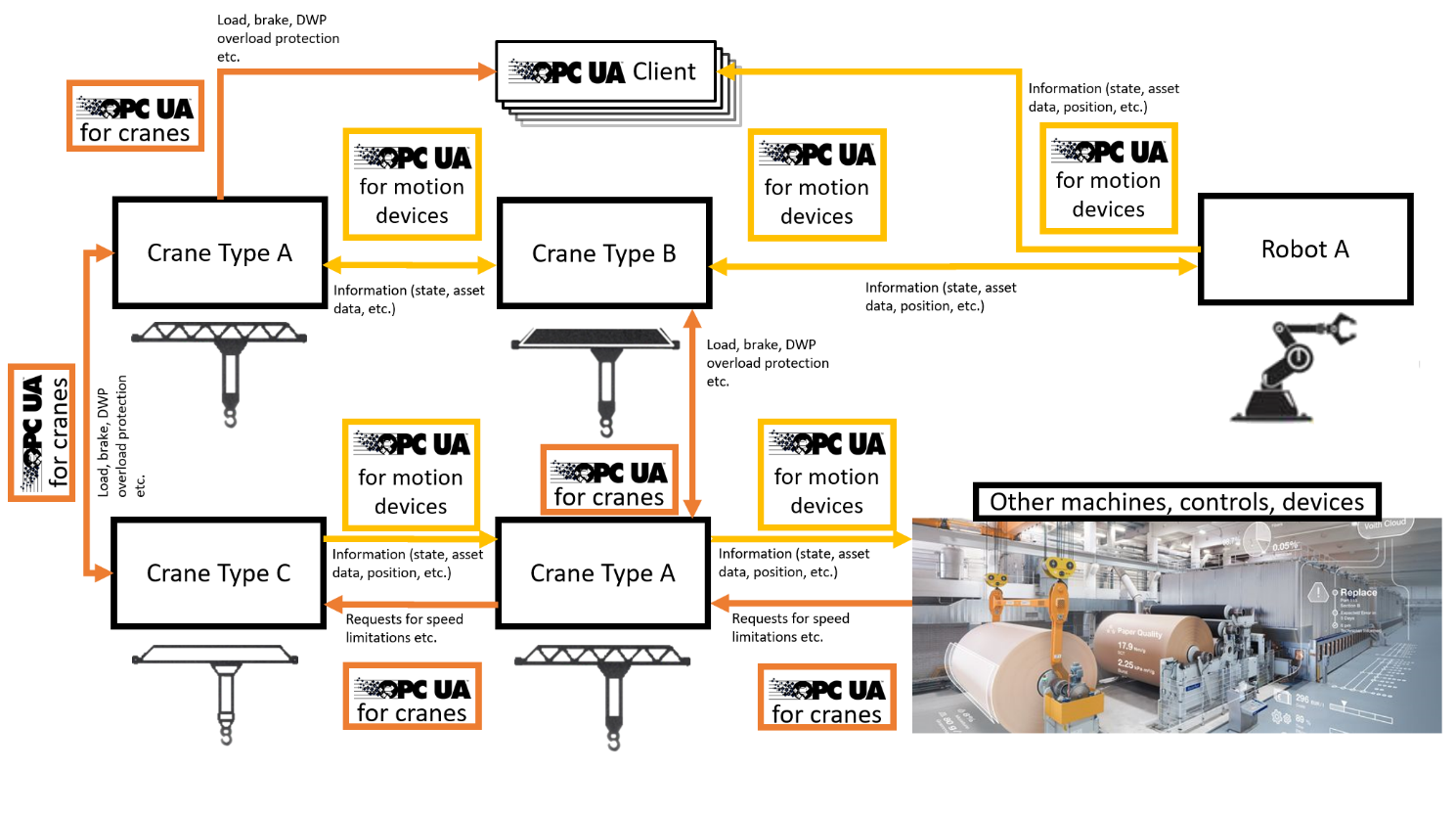
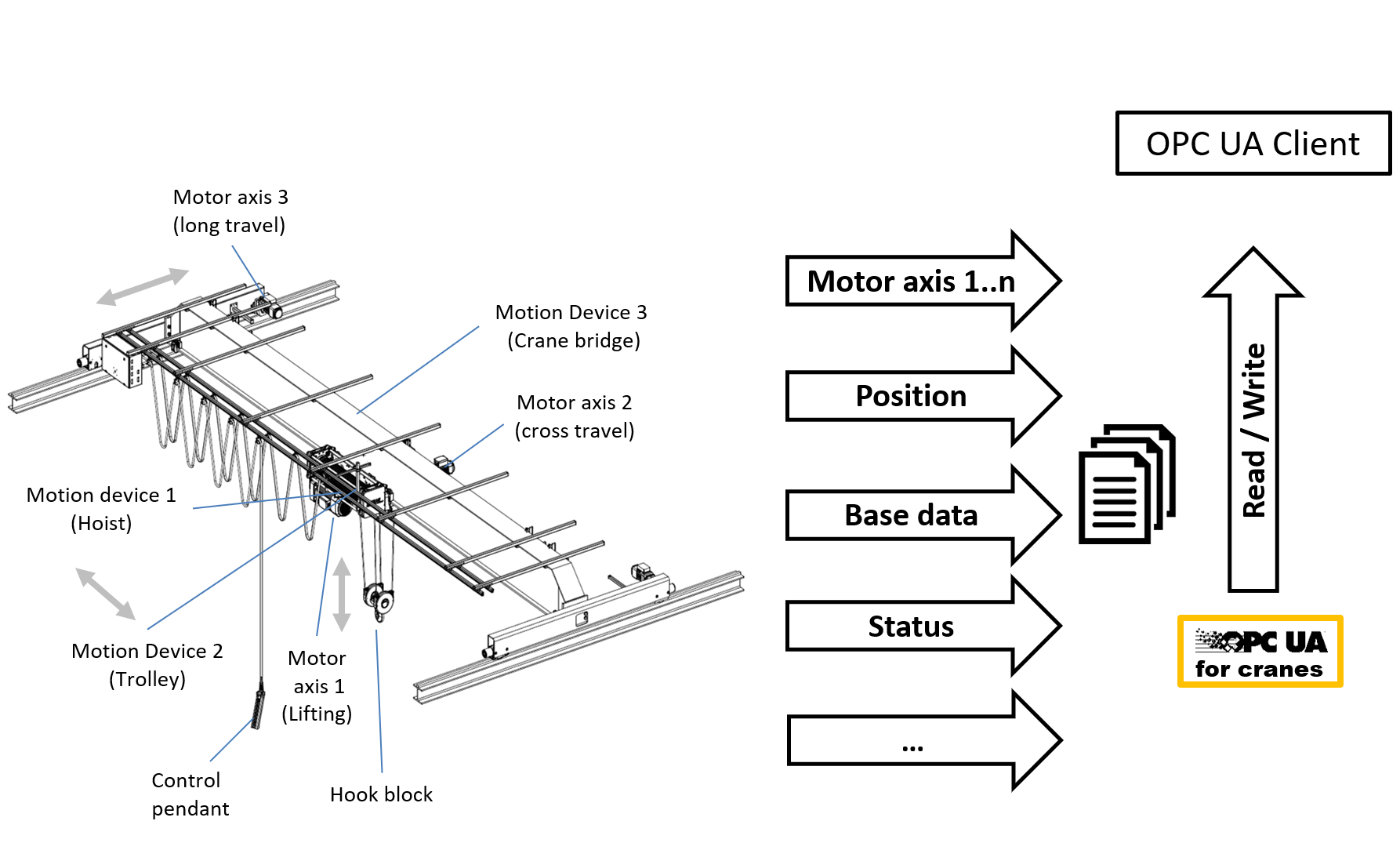
Figure 7 describes the semantic self-description with OPC UA for Cranes and Hoists.
6 OPC UA for Cranes and Hoists Information Model overview
The CraneMotionDeviceSystemType is used as the root object representing the motion device system with all its subcomponents. The CraneMotionDeviceSystemType is derived from the MotionDeviceSystemType (OPC UA for Robotics) as a subtype of the ComponentType (OPC UA for Devices). For MachineryItemIdentification OPC UA for Machinery is applied, see Figure 8.
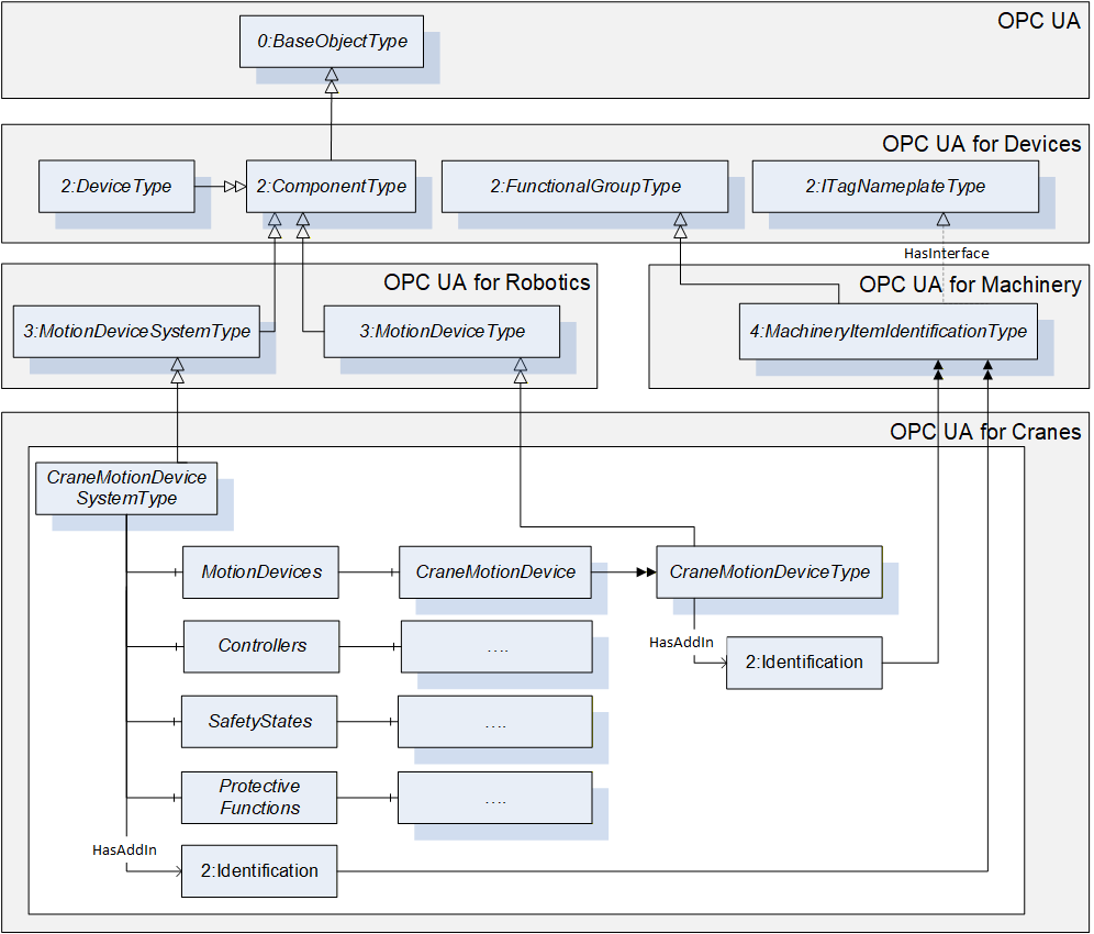
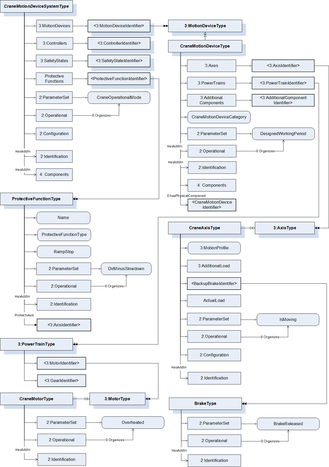
Figure 9 shows the main objects and the relations between them in an abstract view.
In Part 1 in general all variables and properties are read only unless stated otherwise in the description. A vendor can decide to provide variables or properties as writeable by client side as well.
7 OPC UA ObjectTypes
7.1 CraneMotionDeviceSystemType ObjectType Definition
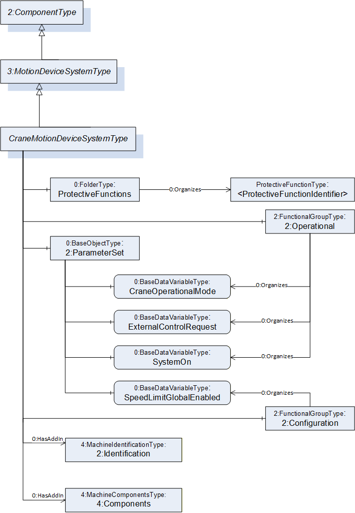
The CraneMotionDeviceSystemType provides a representation of a crane motion device system as an entry point to the OPC UA device set. At least one instance of a CraneMotionDeviceSystemType must be instantiated in the DeviceSet. This instance organises the information model of a complete crane system using instances of the described ObjectTypes.
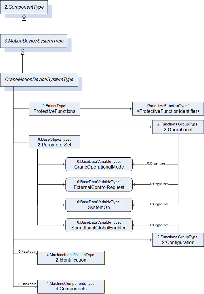
The CraneMotionDeviceSystemType represents the entire crane and contains its various components. The type is a subtype of the OPC 40010-1 MotionDeviceSystemType (OPC Robotics) and this is intended to provide compatibility with OPC 40010-1 aware clients. The CraneMotionDeviceSystemType is formally defined in Table 12.
| Attribute | Value | ||||
| BrowseName | CraneMotionDeviceSystemType | ||||
| IsAbstract | False | ||||
| References | Node Class | BrowseName | DataType | TypeDefinition | Other |
|---|---|---|---|---|---|
| Subtype of the 3:MotionDeviceSystemType defined in OPC 40010-1, i.e. inheriting the InstanceDeclarations of that Node. | |||||
| 0:HasComponent | Object | 2:ParameterSet | 0:BaseObjectType | M | |
| 0:HasComponent | Object | ProtectiveFunctions | 0:FolderType | O | |
| 0:HasAddIn | Object | 2:Identification | 4:MachineIdentificationType | M | |
| 0:HasAddIn | Object | 4:Components | 4:MachineComponentsType | O | |
| 0:HasComponent | Object | 2:Operational | 2:FunctionalGroupType | O | |
| 0:HasComponent | Object | 2:Configuration | 2:FunctionalGroupType | O | |
| Conformance Units | |||||
|---|---|---|---|---|---|
| Cranes Base Info CraneMotionDeviceSystemType |
ParameterSet contains all the variables of the CraneMotionDeviceSystemType. variables are also referenced by an Organizes from either Configuration or Operational FunctionalGroup.
ProtectiveFunctions is a Folder for both hardware and software functions designed to affect motion of the crane in order to protect personnel, equipment and/or the environment. Examples include force limiters (overload protection), limit switches and software anti-collision systems. A protective function can slow down and/or stop the motion of the crane in one or more axis.
The Identification Object provides identification information of the crane. It is specified in OPC 10000-100 and OPC 40001-1.
As defined in OPC 40001-1 4:Components allows the listing of all subcomponents of a CraneMotionDeviceSystem.
The Operational FunctionalGroup contains variables which represent the current state of the crane (motion device system). This is read-only, online data.
The Configuration FunctionalGroup contains variables which can be used to assess and/or affect the control of the crane, such as setting a speed limit for crane motions.
The components of the CraneMotionDeviceSystemType have additional subcomponents which are defined in Table 13.
| BrowsePath | References | NodeClass | BrowseName | DataType | TypeDefinition | Others |
| 2:ParameterSet | 0:HasComponent | Variable | CraneOperationalMode | CraneOperationalModeEnum | 0:BaseDataVariableType | M, RO |
| 2:ParameterSet | 0:HasComponent | Variable | ExternalControlRequest | ExternalControlRequestEnum | 0:BaseDataVariableType | O, RO |
| 2:ParameterSet | 0:HasComponent | Variable | SpeedLimitGlobalEnabled | 0:Boolean | 0:BaseDataVariableType | O, RW |
| 2:ParameterSet | 0:HasComponent | Variable | SystemOn | 0:Boolean | 0:BaseDataVariableType | M, RO |
| 2:Operational | 0:Organizes | Variable | CraneOperationalMode | CraneOperationalModeEnum | 0:BaseDataVariableType | M, RO |
| 2:Operational | 0:Organizes | Variable | ExternalControlRequest | ExternalControlRequestEnum | 0:BaseDataVariableType | O, RO |
| 2:Operational | 0:Organizes | Variable | SystemOn | 0:Boolean | 0:BaseDataVariableType | M, RO |
| 2:Configuration | 0:Organizes | Variable | SpeedLimitGlobalEnabled | 0:Boolean | 0:BaseDataVariableType | O, RW |
| ProtectiveFunctions | 0:HasComponent | Object | <ProtectiveFunctionIdentifier> | ProtectiveFunctionType | MP |
The parameter CraneOperationalMode provides information to the client about the mode of operation the crane is in. See Table 25 for the possible values for the mode enumerations and their descriptions.
The parameter ExternalControlRequestEnum provides information to the client about whether an external control request is active on the crane and other information about external controls. See Table 27 for the possible values for the mode enumeration and their descriptions.
The parameter SpeedLimitGlobalEnabled provides information to the client whether a global speed limit has been requested by a client. TRUE if a limitation has been requested, otherwise FALSE.
The parameter SystemOn provides information to the client whether the main power supply and all subject systems are able to operate the crane in less than an approximate value of 10 seconds requiring no more than one operator action. TRUE if able to operate in less than 10 seconds, otherwise FALSE. This timing can be higher in some special applications.
The parameter SpeedLimitGlobalEnable is a read/write variable used to enable and/or disable any and all speed limitations for this specific CraneMotionDeviceSystemType. TRUE if speed limitations are to be obeyed, otherwise FALSE.
The ProtectiveFunctions folder contain information about crane functions which are designed to protect personnel, equipment, the environment and/or the crane itself, described in detail by ProtectiveFunctionType. The use case is similar to OPC 40010-1 ProtectiveStopFunctionType and EmergencyStopFunctionType (OPC Robotics), but with the additional capability to also represent functions which slow down motions (instead of stopping) or stop motions in one direction while still allowing it in the other direction.
Note: If possible each of the values given in 2:ParameterSet should be instantiated and referenced again from their respective FunctionalGroup (Operational or Configuration).
7.2 CraneMotionDeviceType ObjectType Definition
7.2.1 Overview
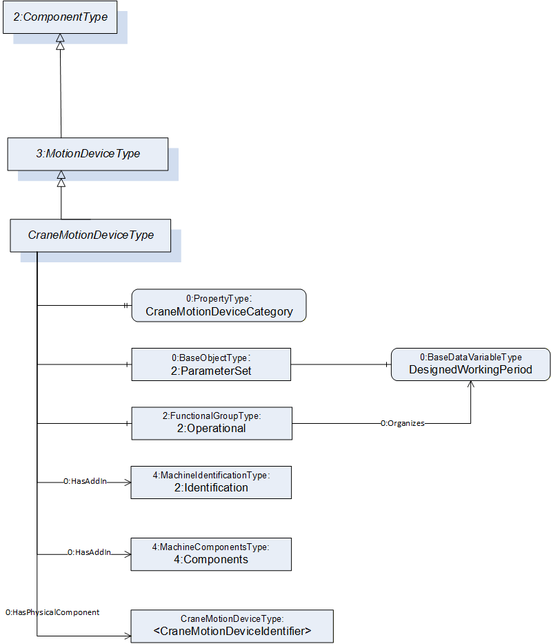
The CraneMotionDeviceType represents a physical moving component of the crane, such as a hoisting machinery or trolley. Load lifting attachments of the crane can also be represented as CraneMotionDeviceType objects.
The type is a subtype of the OPC 40010-1 MotionDeviceType and this is intended to provide compatibility with OPC 40010-1 aware clients. CraneMotionDeviceType is formally defined in Table 14.
| Attribute | Value | ||||
| BrowseName | CraneMotionDeviceType | ||||
| IsAbstract | False | ||||
| References | Node Class | BrowseName | DataType | TypeDefinition | Other |
|---|---|---|---|---|---|
| Subtype of the 3:MotionDeviceType defined in OPC 40010-1, i.e. inheriting the InstanceDeclarations of that Node. | |||||
| 0:HasAddIn | Object | 2:Identification | 4:MachineIdentificationType | M | |
| 0:HasAddIn | Object | 4:Components | 4:MachineComponentsType | O | |
| 0:HasComponent | Object | 2:Operational | 2:FunctionalGroupType | O | |
| 0:HasProperty | Variable | CraneMotionDeviceCategory | CraneMotionDeviceCategoryEnum | 0:PropertyType | M, RO |
| 0:HasPhysicalComponent | Object | <CraneMotionDeviceIdentifier> | CraneMotionDeviceType | OP | |
| Conformance Units | |||||
|---|---|---|---|---|---|
| Cranes Base Info CraneMotionDeviceType |
The Operational FunctionalGroup contains variables which represent the current state of the crane component (motion device). This is read-only, online data.
ParameterSet contains all the variables of the CraneMotionDeviceSystemType. Variables are also referenced by an Organizes from the Operational FunctionalGroup.
The Identification Object provides identification information of the crane component. It is specified in OPC 10000-100 and OPC 40001-1.
As defined in OPC 40001-1 4:Components allows the listing of all subcomponents of a CraneMotionDevice.
Note: If possible each of the values given in 2:ParameterSet should be instantiated and referenced again from the Operational FunctionalGroup.
CraneMotionDeviceCategory property describes which category this motion device belongs to in the domain of material handling. The enumeration contains different categories including hoists, trolley traversing machineries, bridge or gantry travelling machineries, load lifting attachments etc.
The <CraneMotionDeviceIdentifier> Object with its Hierarchical Reference HasPhysicalComponent shall be used to reflect the physical relationship between CraneMotionDeviceTypes. The Forward Direction of this reference represents the relationship component to subcomponent. Only direct subcomponents shall be referenced via HasPhysicalComponent Reference
The components of the CraneMotionDeviceType have additional subcomponents which are defined in Table 15.
| BrowsePath | References | NodeClass | BrowseName | DataType | TypeDefinition | Others |
| 2:ParameterSet | 0:HasComponent | Variable | DesignedWorkingPeriod | 0:Double | 0:AnalogUnitType | O, RO |
| 2:Operational | 0:Organizes | Variable | DesignedWorkingPeriod | 0:Double | 0:AnalogUnitType | O, RO |
The DesignedWorkingPeriod variable contains the lowest ISO 12482 designed working period (DWP) value of this component, if available. It is a percentage, initial value: 100.0%.
7.3 CraneAxisType ObjectType Definition
7.3.1 Overview
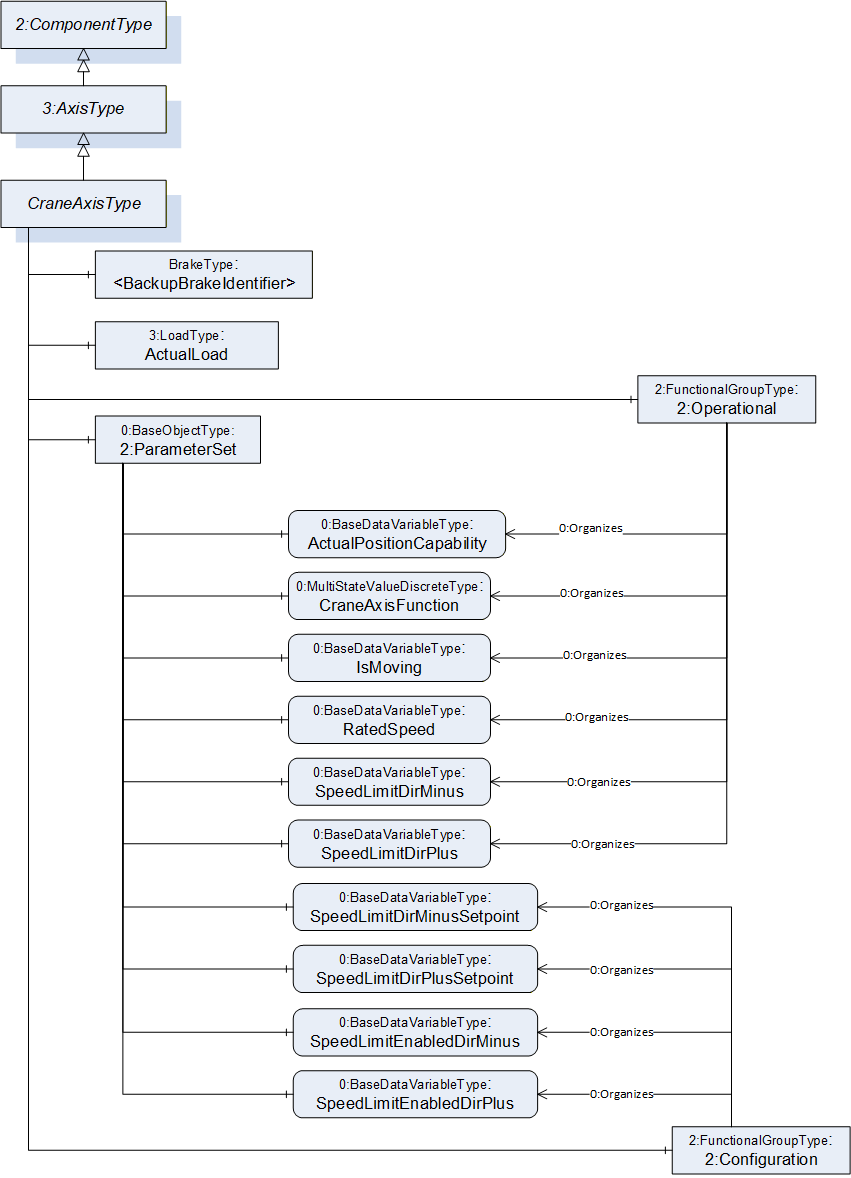
The CraneAxisType represents the crane axis and contains its various components. The type is a subtype of the OPC 40010-1 AxisType (OPC Robotics) and this is intended to provide compatibility with OPC 40010-1 aware clients. The CraneAxisType is formally defined in Table 16.
| Attribute | Value | ||||
| BrowseName | CraneAxisType | ||||
| IsAbstract | False | ||||
| References | Node Class | BrowseName | DataType | TypeDefinition | Other |
|---|---|---|---|---|---|
| Subtype of the 3:AxisType defined in OPC 40010-1, i. e. inheriting the InstanceDeclarations of that Node. | |||||
| 0:HasComponent | Object | ActualLoad | 3:LoadType | O | |
| 0:HasComponent | Object | <BackupBrakeIdentifier> | BrakeType | OP | |
| 0:HasComponent | Object | 2:Configuration | 2:FunctionalGroupType | O | |
| 0:HasComponent | Object | 2:Operational | 2:FunctionalGroupType | O | |
| Conformance Units | |||||
|---|---|---|---|---|---|
| Cranes Base Info CraneAxisType |
The ActualLoad object represents the load lifted by the crane. This object is mostly used in hoisting axis. The type (LoadType) is the one defined by OPC 40010-1 (OPC Robotics) and is used to represent the mass of the load, and optionally also inertia and/or the center of mass.
The <BackupBrakeIdentifier> object indicates that the axis may contain one or more backup brakes represented by BrakeType instances.
The Operational FunctionalGroup contains variables which represent the current state of the axis. These are read-only variables.
The Configuration FunctionalGroup contains variables which can be used to assess and/or affect the control of the axis, such as setting speed limits.
The components of the CraneAxisType have additional subcomponents which are defined in Table 17.
| BrowsePath | References | NodeClass | BrowseName | DataType | TypeDefinition | Others |
| 2:ParameterSet | 0:HasComponent | Variable | ActualPositionCapability | 0:Boolean | 0:BaseDataVariableType | M, RO |
| 2:ParameterSet | 0:HasComponent | Variable | CraneAxisFunction | 0:UInt16[] | 0:MultiStateValueDiscreteType | O, RO |
| 2:ParameterSet | 0:HasComponent | Variable | IsMoving | 0:Boolean | 0:BaseDataVariableType | O, RO |
| 2:ParameterSet | 0:HasComponent | Variable | RatedSpeed | 0:Double | 0:AnalogUnitType | O, RO |
| 2:ParameterSet | 0:HasComponent | Variable | SpeedLimitDirMinus | 0:Double | 0:AnalogUnitType | O, RO |
| 2:ParameterSet | 0:HasComponent | Variable | SpeedLimitDirMinusSetpoint | 0:Double | 0:AnalogUnitType | O, RW |
| 2:ParameterSet | 0:HasComponent | Variable | SpeedLimitDirPlus | 0:Double | 0:AnalogUnitType | O, RO |
| 2:ParameterSet | 0:HasComponent | Variable | SpeedLimitDirPlusSetpoint | 0:Double | 0:AnalogUnitType | O, RW |
| 2:ParameterSet | 0:HasComponent | Variable | SpeedLimitEnabledDirMinus | 0:Boolean | 0:BaseDataVariableType | O, RW |
| 2:ParameterSet | 0:HasComponent | Variable | SpeedLimitEnabledDirPlus | 0:Boolean | 0:BaseDataVariableType | O, RW |
| 2:Operational | 0:Organizes | Variable | ActualPositionCapability | 0:Boolean | 0:BaseDataVariableType | M, RO |
| 2:Operational | 0:Organizes | Variable | CraneAxisFunction | 0:UInt16[] | 0:MultiStateValueDiscreteType | O, RO |
| 2:Operational | 0:Organizes | Variable | IsMoving | 0:Boolean | 0:BaseDataVariableType | O, RO |
| 2:Operational | 0:Organizes | Variable | RatedSpeed | 0:Double | 0:AnalogUnitType | O, RO |
| 2:Operational | 0:Organizes | Variable | SpeedLimitDirMinus | 0:Double | 0:AnalogUnitType | O, RO |
| 2:Operational | 0:Organizes | Variable | SpeedLimitDirPlus | 0:Double | 0:AnalogUnitType | O, RO |
| 2:Configuration | 0:Organizes | Variable | SpeedLimitDirMinusSetpoint | 0:Double | 0:AnalogUnitType | O, RW |
| 2:Configuration | 0:Organizes | Variable | SpeedLimitDirPlusSetpoint | 0:Double | 0:AnalogUnitType | O, RW |
| 2:Configuration | 0:Organizes | Variable | SpeedLimitEnabledDirMinus | 0:Boolean | 0:BaseDataVariableType | O, RW |
| 2:Configuration | 0:Organizes | Variable | SpeedLimitEnabledDirPlus | 0:Boolean | 0:BaseDataVariableType | O, RW |
The ActualPositionCapability describes if the crane is able to give the position of the axis. The crane must be equipped with the necessary devices to provide this type of information. If the variable value is True, the axis position can be obtained from the variable ActualPosition inherited from the OPC 40010-1 (OPC Robotics).
The CraneAxisFunction describes the axis operating mode. The possible values are described in Table 18.
The IsMoving indicates if the axis is moving (TRUE) or not (FALSE).
The RatedSpeed indicates the rated (nominal) speed of the axis.
The SpeedLimitDirMinus indicates the speed limitation value active on the control system, in direction where position value decreases, in percentage of rated speed, range [0%..100%].
The SpeedLimitDirMinusSetpoint indicates the speed limitation request written from client, in direction where position value decreases, in percentage of rated speed, range [0%..100%].
The SpeedLimitEnabledDirMinus indicates a speed limitation request active, written from client, in direction where position value decreases. True if a client requests the speed to be limited in this direction, false if speed doesn't need to be limited.
The SpeedLimitDirPlus indicates the speed limitation value active on the control system, in direction where position value increases, in percentage of rated speed, range [0%..100%].
The SpeedLimitDirPlusSetpoint indicates the speed limitation request written from client, in direction where position value increases, in percentage of rated speed, range [0%..100%].
The SpeedLimitEnabledDirPlus indicates a speed limitation request active, written from client, in direction where position value increases. True if a client requests the speed to be limited in this direction, false if speed doesn't need to be limited.
7.3.2 Variable CraneAxisFunction
To be extendable for vendor specific extensions later, the TypeDefinition is MultiStateValueDiscreteType with its mandatory Properties EnumValues and ValueAsText must be filled with the supported values which are defined in Table 18. The EnumValues Property is an array of EnumValueType. Each entry of the array represents one enumeration value with its integer notation, a human-readable representation (DisplayName), and a description. Each instance shall have the values 0 to 8, which are defined in Table 18. Element numbers 9-15 are reserved for future use. If vendors add specific elements, the range 9-15 shall be filled with 'null'-strings. The variable CraneAxisFunction exposes the current integer notation in their Value Attribute. The ValueAsText Property shall provide the localized text representation of the current enumeration value (Value Attribute of Variable CraneAxisFunction).
| DisplayName | Value | Description |
| RATED_SPEED | 0 | The axis moves at rated speed. |
| EXTENDED_SPEED | 1 | The axis moves above the rated speed when load is under certain percentage of rated load. This function reduces the load cycle time and can be used for hoisting. |
| MICROSPEED | 2 | Microspeed turns large joystick movements on the operator interface into slow and exact load movements. This function assists in very accurate and precise load handling and reduces the risk of collision and can be used for hoisting and travelling. |
| INCHING | 3 | Inching is designed to ensure accurate final load positioning by allowing the crane operator to move the load in small increments. This function assists in very accurate and precise load handling and reduces the risk of collision and can be used for hoisting and travelling. |
| ANTISWAY | 4 | This function limits load swing by controlling the bridge and trolley acceleration and deceleration. Antisway allows faster load handling and more precise positioning. This feature also reduces the risk of damage to the load, crane and surrounding area. |
| TANDEM_HOIST | 5 | Two or more hoists are operated from a single control station for handling of a single load. Two or more load lifting attachments'/hooks' positions are synchronized. This function gives more accuracy when two or more hoists are used at the same time. Hoisting speeds are the same within the tolerances required for the particular application. |
| TANDEM_TROLLEY | 6 | Two or more trolleys are operated from a single control station for handling of a single load. Horizontal speeds are the same within the tolerances required for the particular application. |
| TANDEM_CRANE | 7 | This function allows the operator to control two cranes at the same time from one control station. The operator controls two cranes as one. This feature is useful when the operator needs to handle a single load with two cranes. |
| PRESET_DESTINATION | 8 | This function allows the operator to move the crane to a predefined position without effort. With a single operator input, the crane carries out the sequence to reach the selected destination. |
| null | 9 - 15 | null |
| Vendor specific | ≥ 16 | Vendor specific description |
7.4 BrakeType ObjectType Definition
The BrakeType is used to describe the status of a brake. In this specification, it is only defined to model the backup brakes. A service brake status is provided by the BrakeReleased variable of the OPC 40010-1 (OPC Robotics) MotorType object. The Figure 13 shows an overview of this type.
The BrakeType represents the backup brake and contains its various components. The BrakeType is formally defined in Table 19.
| Attribute | Value | ||||
| BrowseName | BrakeType | ||||
| IsAbstract | False | ||||
| References | Node Class | BrowseName | DataType | TypeDefinition | Other |
|---|---|---|---|---|---|
| Subtype of the 2:ComponentType defined in OPC 10000-100, i. e. inheriting the InstanceDeclarations of that Node. | |||||
| 0:HasComponent | Object | 2:Operational | 2:FunctionalGroupType | O | |
| 0:HasComponent | Object | 2:ParameterSet | 0:BaseObjectType | M | |
| 0:HasAddIn | Object | 2:Identification | 4:MachineryComponentIdentificationType | O | |
| Conformance Units | |||||
|---|---|---|---|---|---|
| Cranes Base Info BrakeType |
The Identification Object provides identification information of the brake. It is specified in OPC 10000-100 and OPC 40001-1.
ParameterSet contains all the variables of the BrakeType. Variables are also referenced by an Organizes from Operational FunctionalGroup.
The components of the BrakeType have additional subcomponents which are defined in Table 20.
| BrowsePath | References | NodeClass | BrowseName | DataType | TypeDefinition | Others |
| 2:ParameterSet | 0:HasComponent | Variable | BrakeReleased | 0:Boolean | 0:BaseDataVariableType | M, RO |
| 2:Operational | 0:Organizes | Variable | BrakeReleased | 0:Boolean | 0:BaseDataVariableType | M, RO |
The BrakeReleased variable describes the current state of the brake. It is TRUE when the brake is not engaged and FALSE when the brake is stopping the motion.
7.5 CraneMotorType ObjectType Definition
The CraneMotorType describes a motor in a power train. The Figure 14 shows an overview of this type.
The CraneMotorType represents a motor in a power train and contains its various components. The type is a subtype of the OPC 40010-1 MotorType (OPC Robotics) and this is intended to provide compatibility with OPC 40010-1 aware clients. The CraneMotorType is formally defined in Table 21.
| Attribute | Value | ||||
| BrowseName | CraneMotorType | ||||
| IsAbstract | False | ||||
| References | Node Class | BrowseName | DataType | TypeDefinition | Other |
|---|---|---|---|---|---|
| Subtype of the 3:MotorType defined in OPC 10000-100, i. e. inheriting the InstanceDeclarations of that Node. | |||||
| 0:HasAddIn | Object | 2:Identification | 4:MachineryComponentIdentificationType | O | |
| 0:HasComponent | Object | 2:Operational | 2:FunctionalGroupType | O | |
| Conformance Units | |||||
|---|---|---|---|---|---|
| Cranes Base Info CraneMotorType |
The Identification Object provides identification information of the motor. It is specified in OPC 10000-100 and OPC 40001-1.
The Operational FunctionalGroup contains variables which represent the current state of the motor. This is read-only.
The components of the CraneMotorType have additional subcomponents which are defined in Table 22.
| BrowsePath | References | NodeClass | BrowseName | DataType | TypeDefinition | Others |
| 2:ParameterSet | 0:HasComponent | Variable | Overheated | 0:Boolean | 0:BaseDataVariableType | O, RO |
| 2:Operational | 0:Organizes | Variable | Overheated | 0:Boolean | 0:BaseDataVariableType | O, RO |
The Overheated variable describes if the motor exceeds the maximum operating temperature. Overheated is TRUE if the motor temperature is above the limit. FALSE otherwise.
7.6 ProtectiveFunctionType ObjectType Definition
7.6.1 Overview
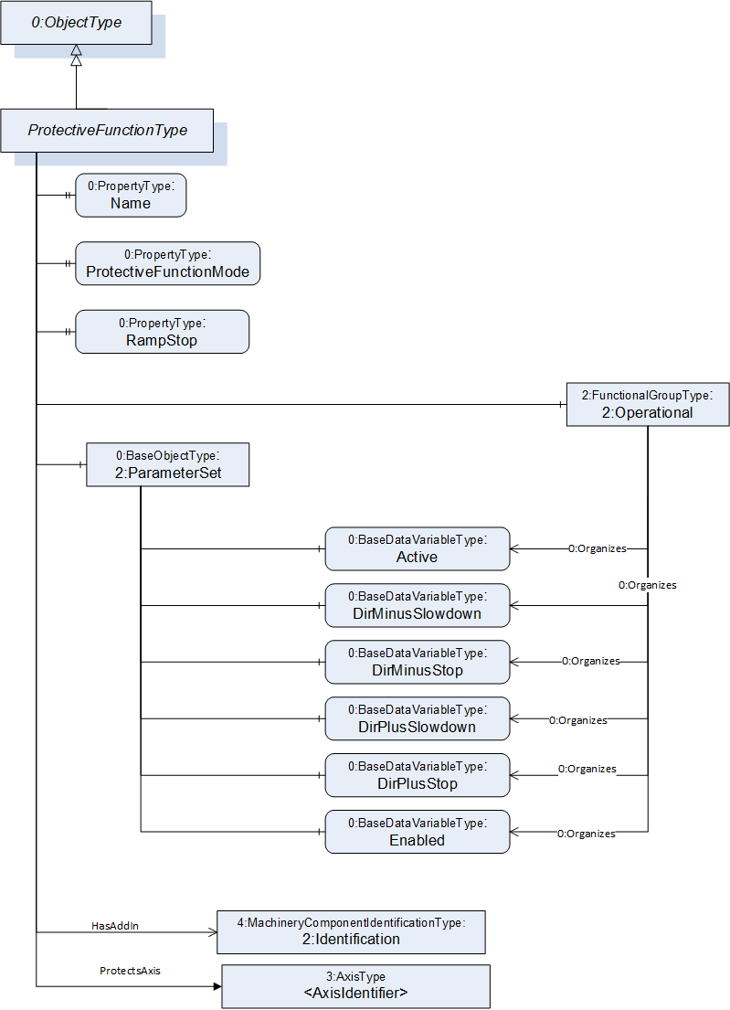
The ProtectiveFunctionType represents a hardware or software function designed to affect motion of the crane in order to protect personnel, equipment and/or the environment. Examples include force limiters (overload protection), limit switches and software anti-collision systems. A protective function can slow down and/or stop the motion of the crane in one or more axis. The use case is similar to OPC 40010-1 ProtectiveStopFunctionType and EmergencyStopFunctionType (OPC Robotics), but with the additional capability to also represent functions which slow down motions (instead of stopping) or stop motions in one direction while still allowing it in the other direction. ProtectiveFunctionType is formally defined in Table 23.
| Attribute | Value | ||||
| BrowseName | ProtectiveFunctionType | ||||
| IsAbstract | False | ||||
| References | Node Class | BrowseName | DataType | TypeDefinition | Other |
|---|---|---|---|---|---|
| Subtype of the 0:BaseObjectType defined in OPC 10000-100, i. e. inheriting the InstanceDeclarations of that Node. | |||||
| 0:HasAddIn | Object | 2:Identification | 4:MachineryComponentIdentificationType | O | |
| 0:HasComponent | Object | 2:ParameterSet | 0:BaseObjectType | M | |
| 0:HasComponent | Object | 2:Operational | 2:FunctionalGroupType | O | |
| 0:HasProperty | Variable | Name | 0:String | 0:PropertyType | O, RO |
| 0:HasProperty | Variable | ProtectiveFunctionMode | ProtectiveFunctionEnum | 0:PropertyType | O, RO |
| 0:HasProperty | Variable | RampDown | 0:Boolean | 0:PropertyType | O, RO |
| Conformance Units | |||||
|---|---|---|---|---|---|
| Cranes Base Info ProtectiveFunctionType |
The Name variable contains a human-readable textual identifier of the function.
The Identification Object provides identification information of the protective function. It is specified in OPC 10000-100 and OPC 40001-1.
The Operational FunctionalGroup contains variables which represent the current state of the protective function. This is read-only.
The ProtectiveFunctionMode variable describes what kind of protective function a specific instance of ProtectiveFunctionType describes, e. g. force limiter for overload protection devices or motion limiter for limit switches etc. The enumeration is defined in 8.4 ProtectiveFunctionEnum.
The components of the ProtectiveFunctionType have additional subcomponents which are defined in Table 17.
The RampDown Property indicates where a motion is slowed down using a graceful ramp down e.g. using software functionality instead of brakes.
An instance of the ProtectiveFunctionType can have multiple associated axis, instances of the 3:AxisType, which are protected by the protective function. The Non-Hierarchical Reference ProtectsAxis is used to express this relation. For more information on this reference, see section 9.1.
| BrowsePath | References | NodeClass | BrowseName | DataType | TypeDefinition | Others |
| 2:ParameterSet | 0:HasComponent | Variable | Active | 0:Boolean | 0:BaseDataVariableType | O, RO |
| 2:ParameterSet | 0:HasComponent | Variable | DirMinusSlowdown | 0:Boolean | 0:BaseDataVariableType | O, RO |
| 2:ParameterSet | 0:HasComponent | Variable | DirMinusStop | 0:Boolean | 0:BaseDataVariableType | O, RO |
| 2:ParameterSet | 0:HasComponent | Variable | DirPlusSlowdown | 0:Boolean | 0:BaseDataVariableType | O, RO |
| 2:ParameterSet | 0:HasComponent | Variable | DirPlusStop | 0:Boolean | 0:BaseDataVariableType | O, RO |
| 2:ParameterSet | 0:HasComponent | Variable | Enabled | 0:Boolean | 0:BaseDataVariableType | O, RO |
| 2:Operational | 0:Organizes | Variable | Active | 0:Boolean | 0:BaseDataVariableType | O, RO |
| 2:Operational | 0:Organizes | Variable | DirMinusSlowdown | 0:Boolean | 0:BaseDataVariableType | O, RO |
| 2:Operational | 0:Organizes | Variable | DirMinusStop | 0:Boolean | 0:BaseDataVariableType | O, RO |
| 2:Operational | 0:Organizes | Variable | DirPlusSlowdown | 0:Boolean | 0:BaseDataVariableType | O, RO |
| 2:Operational | 0:Organizes | Variable | DirPlusStop | 0:Boolean | 0:BaseDataVariableType | O, RO |
| 2:Operational | 0:Organizes | Variable | Enabled | 0:Boolean | 0:BaseDataVariableType | O, RO |
The Active variable provides information about the protective function state. It is TRUE if this particular protective function is active, i. e. that a stop or slowdown is initiated, FALSE otherwise. If Enabled is FALSE, then Active shall be FALSE.
The DirMinusSlowdown variable provides information about the speed reduction capabilities of the protective function. When TRUE, slowdown movement is enabled for direction where position value decreases (minus).
The DirMinusStop variable provides information about the stop capabilities of the protective function. When TRUE, Stop is enabled for direction where position value decreases (minus).
The DirPlusSlowdown variable provides information about the speed reduction capabilities of the protective function. When TRUE, slowdown movement is enabled for direction where position value increases (plus).
The DirPlusStop variable provides information about the stop capabilities of the protective function. When TRUE, stop is enabled for direction where position value increases (plus).
The Enabled variable provides information about the availability of the protective function. It is TRUE if this protective function is currently supervising the system, FALSE otherwise. A protective function may or may not be enabled at all times, e. g. the protective stop function of the safety doors are typically enabled in automatic operational mode and disabled in manual mode.
8 OPC UA DataTypes
8.1 CraneOperationalModeEnum
The enumeration CraneOperationModeEnum represents the mode of operation the crane is in. A crane can be in MANUAL, SEMIAUTOMATIC, FULLAUTOMATIC, BYPASS_ON or MAINTENANCE mode. The enumeration also allows OTHER, vendor specific modes to be represented. Table 25 below describes the possible values for the mode enumerations and their descriptions.
The enumeration is defined in Table 25.
| Name | Value | Description |
| OTHER | 0 | Use if vendor specific |
| MANUAL | 1 | Crane is operated manually by a human operator |
| SEMIAUTOMATIC | 2 | Some or all of crane motions are automated, but a human operator is required in the loop. |
| FULLAUTOMATIC | 3 | All of the crane motions are automated. No human intervention is required. |
| BYPASS_ON | 4 | A function, such as an assistive feature, is bypassed on the crane, e. g. to continue productive work in case a non-critical function suffers a fault. |
| MAINTENANCE | 5 | Crane is in maintenance mode, typically operating at reduced speed and possibly with some protective functions disabled so they will not hinder or prohibit service activities. |
Its representation in the AddressSpace is defined in Table 26.
| Attribute | Value | |||||
| BrowseName | CraneOperationalModeEnum | |||||
| IsAbstract | False | |||||
| References | NodeClass | BrowseName | DataType | TypeDefinition | Other | |
|---|---|---|---|---|---|---|
| Subtype of the 0:Enumeration type defined in OPC 10000-5 | ||||||
| 0:HasProperty | Variable | 0:EnumValues | 0:EnumValueType[] | 0:PropertyType | ||
| Conformance Units | ||||||
|---|---|---|---|---|---|---|
| Crane Base Info CraneOperationalModeEnum |
8.2 ExternalControlRequestEnum
The enumeration ExternalControlRequestEnum provides information to the client about whether an external control request is active on the crane and other information about external controls. See Table 27 for the possible values for the mode enumeration and their descriptions.
The enumeration is defined in Table 27.
| Name | Value | Description |
| NOT_REQUESTED | 0 | No control request inputs have been received from any client |
| REQUESTED_AND_CONTROL_ACTIVE | 1 | Control request input has been received from a client and the request is being applied to the control |
| REQUESTED_AND_CONTROL_INACTIVE | 2 | Control request input has been received from a client but the request is not currently being applied to the control |
| REQUESTED_AND_CONTROL_BYPASSED | 3 | Control request input has been received from a client but the request is not currently being applied to the control because it has been bypassed in the control system |
Its representation in the AddressSpace is defined in Table 28.
.
| Attribute | Value | |||||
| BrowseName | ExternalControlRequestEnum | |||||
| IsAbstract | False | |||||
| References | NodeClass | BrowseName | DataType | TypeDefinition | Other | |
|---|---|---|---|---|---|---|
| Subtype of the 0:Enumeration type defined in OPC 10000-5 | ||||||
| 0:HasProperty | Variable | 0:EnumValues | 0:EnumValueType[] | 0:PropertyType | ||
| Conformance Units | ||||||
|---|---|---|---|---|---|---|
| Crane Base Info ExternalControlRequestEnum |
8.3 CraneMotionDeviceCategoryEnum
This enumeration CraneMotionDeviceCategoryEnum is used to denote which type of crane motion device a specific instance of CraneMotionDeviceType is. This can be used to, for example, identify the machineries when performing certain operations only for e.g. hoisting machineries. The enumeration is defined in Table 29.
| Name | Value | Description |
| HOIST | 0 | Hoisting machinery |
| TROLLEY_TRAVERSE | 1 | Trolley traverse or cross travel machinery |
| BRIDGE_OR_GANTRY_TRAVEL | 2 | Bridge or gantry travel, long travel machinery |
| LOAD_LIFTING_ATTACHMENT | 3 | Load lifting attachment |
| ROTATING_OR_SLEWING | 4 | Rotating or slewing machinery |
| LUFFING | 5 | Luffing machinery |
| POWER_SUPPLY_MACHINERY | 6 | Power supply or power delivery |
| OTHER | 7 | Other |
Its representation in the AddressSpace is defined in Table 30.
| Attribute | Value | ||||
| BrowseName | CraneMotionDeviceCategoryEnum | ||||
| IsAbstract | False | ||||
| References | Node Class | BrowseName | DataType | TypeDefinition | Other |
|---|---|---|---|---|---|
| Subtype of the Enumeration type defined in OPC 10000-5 | |||||
| 0:HasProperty | Variable | 0:EnumValues | 0:EnumValueType[] | 0:PropertyType | |
| Conformance Units | |||||
|---|---|---|---|---|---|
| Crane Base Info CraneMotionDeviceCategoryEnum |
8.4 ProtectiveFunctionEnum
The enumeration ProtectiveFunctionEnum variable describes what kind of protective function a specific instance of protective function type describes, e. g. force limiter for overload protection devices or motion limiter for limit switches etc. A protective function represents a hardware or software function designed to affect motion of the crane in order to protect personnel, equipment and/or the environment.
The enumeration is defined in Table 31.
| Name | Value | Description |
| OTHER | 0 | Use if vendor specific |
| FORCE_LIMITER | 1 | Limiting the transmitted force |
| OVERSPEED_CONTROL | 2 | Limiting the speed during operation |
| MOTION_LIMITER | 3 | Limiting by stopping motion |
| ANTICOLLISION | 4 | Device with the ability to bring the moving crane or trolley(s) to a stop before a collision occurs. |
Its representation in the AddressSpace is defined in Table 32.
| Attribute | Value | |||||
| BrowseName | ProtectiveFunctionEnum | |||||
| IsAbstract | False | |||||
| References | NodeClass | BrowseName | DataType | TypeDefinition | Other | |
|---|---|---|---|---|---|---|
| Subtype of the 0:Enumeration type defined in OPC 10000-5 | ||||||
| 0:HasProperty | Variable | 0:EnumValues | 0:EnumValueType[] | 0:PropertyType | ||
| Conformance Units | ||||||
|---|---|---|---|---|---|---|
| Crane Base Info ProtectiveFunctionEnum |
9 OPC UA Reference Types
9.1 ProtectsAxis
The ProtectsAxis is a concrete ReferenceType and can be used directly. It is a subtype of NonHierarchicalReferences.
The semantic of this ReferenceType is to link ProtectiveFunctions to the Axes they protect.
The SourceNode of References of this type shall be an Object of ProtectiveFunctionType.
The TargetNode of this ReferenceType shall be an Object of 3:AxisType.
The ProtectsAxis is formally defined in Table 33.
| Attributes | Value | ||
| BrowseName | ProtectsAxis | ||
| InverseName | AxisProtectedBy | ||
| Symmetric | False | ||
| IsAbstract | False | ||
| References | NodeClass | BrowseName | Comment |
|---|---|---|---|
| Subtype NonHierarchicalReferences | |||
| Conformance Units | |||
|---|---|---|---|
| Crane Base Info ProtectsAxis |
10 Profiles and ConformanceUnits
10.1 Conformance Units
This chapter defines the corresponding Conformance Units for the OPC UA Information Model for Cranes and Hoists.
| Category | Title | Description |
| Server | Cranes Base Info CraneMotionDeviceSystemType | Supports the CraneMotionDeviceSystemType with all its mandatory InstanceDeclarations, and optionally the optional InstanceDeclarations. A CraneMotionDeviceSystemType has to include at least one Instance of a MotionDeviceType or a subtype of MotionDeviceType. |
| Server | Cranes Base Info CraneMotionDeviceType | Supports the CraneMotionDeviceType with all its mandatory InstanceDeclarations, and optionally the optional InstanceDeclarations. |
| Server | Cranes Base Info CraneAxisType | Supports the CraneAxisType with all its mandatory InstanceDeclarations, and optionally the optional InstanceDeclarations. The CraneAxisFunctions EnumValues are given according to the definitions Table 18 in all instances. |
| Server | Cranes Base Info BrakeType | Supports the BrakeType with all its mandatory InstanceDeclarations, and optionally the optional InstanceDeclarations. |
| Server | Cranes Base Info CraneMotorType | Supports the CraneMotorType with all its mandatory InstanceDeclarations, and optionally the optional InstanceDeclarations |
| Server | Cranes Base Info ProtectiveFunctionType | Supports the ProtectiveFunctionType with all its mandatory InstanceDeclarations, and optionally the optional InstanceDeclarations |
| Server | Cranes Base Info CraneOperationalModeEnum | Supports the enumeration type CraneOperationalModeEnum |
| Server | Crane Base Info ExternalControlRequestEnum | Supports the enumeration type ExternalControlRequestEnum |
| Server | Crane Base Info CraneMotionDeviceCategoryEnum | Supports the enumeration type CraneMotionDeviceCategoryEnum |
| Server | Crane Base Info ProtectiveFunctionEnum | Supports the enumeration type ProtectiveFunctionEnum |
| Server | Crane Base Info ProtectsAxis | Supports the reference type ProtectsAxis |
10.2 Profiles
10.2.1 Profile list
http://opcfoundation.org/UA/Robotics/CranesHoists/ lists all Profiles defined in this document and defines their URIs.
| Profile | URI |
| Cranes Basic Server Profile | http://opcfoundation.org/UA-Profile/CranesHoists/Server/Basic |
10.2.2 Server Facets
10.2.2.1 Overview
The following sections specify the Facets available for Servers that implement the companion specification for Cranes and Hoists. Each section defines and describes a Facet or Profile.
10.2.2.2 Cranes Basic Server Profile
Table 36 defines a Profile that describes the functionalities of an OPC UA Server that is used to serve OPC UA CS for Cranes and Hoists Information Model.
| Group | Conformance Unit / Profile Title | Mandatory / Optional |
| Profile | 0:Core 2017 Server Facet http://opcfoundation.org/UA-Profile/Server/Core2017Facet | M |
| Profile | 0:Data Access Server Facet http://opcfoundation.org/UA-Profile/Server/DataAccess | M |
| Machinery | 4:Machinery Machine Identification Server Facet | M |
| Machinery | 4:Machinery Building Block Organization | O |
| Cranes | Cranes Base Info CraneMotionDeviceSystemType | M |
| Cranes | Cranes Base Info CraneMotionDeviceType | M |
| Cranes | Cranes Base Info CraneAxisType | O |
| Cranes | Cranes Base Info BrakeType | O |
| Cranes | Cranes Base Info CraneMotorType | O |
| Cranes | Cranes Base Info ProtectiveFunctionType | O |
| Cranes | Cranes Base Info CraneOperationalModeEnum | O |
| Cranes | Crane Base Info ExternalControlRequestEnum | O |
| Cranes | Crane Base Info CraneMotionDeviceCategoryEnum | M |
| Cranes | Crane Base Info ProtectiveFunctionEnum | O |
| Cranes | Crane Base Info ProtectsAxis | O |
11 Namespaces
11.1 Namespace Metadata
Table 37 defines the namespace metadata for this document. The Object is used to provide version information for the namespace and an indication about static Nodes. Static Nodes are identical for all Attributes in all Servers, including the Value Attribute. See OPC 10000-5 for more details.
The information is provided as Object of type NamespaceMetadataType. This Object is a component of the Namespaces Object that is part of the Server Object. The NamespaceMetadataType ObjectType and its Properties are defined in OPC 10000-5.
The version information is also provided as part of the ModelTableEntry in the UANodeSet XML file. The UANodeSet XML schema is defined in OPC 10000-6.
| Attribute | Value | ||
| BrowseName | http://opcfoundation.org/UA/CranesHoists/ | ||
| Property | DataType | Value | |
|---|---|---|---|
| NamespaceUri | String | http://opcfoundation.org/UA/CranesHoists/ | |
| NamespaceVersion | String | 1.00 | |
| NamespacePublicationDate | DateTime | 2023-09-01 | |
| IsNamespaceSubset | Boolean | False | |
| StaticNodeIdTypes | IdType [] | 0 | |
| StaticNumericNodeIdRange | NumericRange [] | ||
| StaticStringNodeIdPattern | String | ||
11.2 Handling of OPC UA Namespaces
Namespaces are used by OPC UA to create unique identifiers across different naming authorities. The Attributes NodeId and BrowseName are identifiers. A Node in the UA AddressSpace is unambiguously identified using a NodeId. Unlike NodeIds, the BrowseName cannot be used to unambiguously identify a Node. Different Nodes may have the same BrowseName. They are used to build a browse path between two Nodes or to define a standard Property.
Servers may often choose to use the same namespace for the NodeId and the BrowseName. However, if they want to provide a standard Property, its BrowseName shall have the namespace of the standards body although the namespace of the NodeId reflects something else, for example the EngineeringUnits Property. All NodeIds of Nodes not defined in this document shall not use the standard namespaces.
Table 38 provides a list of mandatory and optional namespaces used in and Cranes and Hoists OPC UA Server.
| NamespaceURI | Description | Use |
| http://opcfoundation.org/UA/ | Namespace for NodeIds and BrowseNames defined in the OPC UA specification. This namespace shall have namespace index 0. | Mandatory |
| Local Server URI | Namespace for nodes defined in the local server. This namespace shall have namespace index 1. | Mandatory |
| http://opcfoundation.org/UA/DI/ | Namespace for NodeIds and BrowseNames defined in OPC 10000-100. The namespace index is Server specific. | Mandatory |
| http://opcfoundation.org/UA/Robotics/ | Namespace for NodeIds and BrowseNames defined in OPC UA for Robotics (OPC 40001-1). The namespace index is Server specific. | Mandatory |
| http://opcfoundation.org/UA/Machinery/ | Namespace for NodeIds and BrowseNames defined in OPC UA for Machinery (OPC 40001-1). The namespace index is Server specific. | Mandatory |
| http://opcfoundation.org/UA/CranesHoists/ | Namespace for NodeIds and BrowseNames defined in this document. The namespace index is Server specific. | Mandatory |
| Vendor specific types | A Server may provide vendor-specific types like types derived from ObjectTypes defined in this document in a vendor-specific namespace. | Optional |
| Vendor specific instances | A Server provides vendor-specific instances of the standard types or vendor-specific instances of vendor-specific types in a vendor-specific namespace. It is recommended to separate vendor specific types and vendor specific instances into two or more namespaces. | Mandatory |
Table 39 provides a list of namespaces and their indices used for BrowseNames in this document. The default namespace of this document is not listed since all BrowseNames without prefix use this default namespace.
| NamespaceURI | Namespace Index | Example |
| http://opcfoundation.org/UA/ | 0 | 0:EngineeringUnits |
| http://opcfoundation.org/UA/DI/ | 2 | 2:DeviceRevision |
| http://opcfoundation.org/UA/Robotics/ | 3 | 3:MotionDeviceType |
| http://opcfoundation.org/UA/Machinery/ | 4 | 4:MachineIdentificationType |
Annex A Cranes and Hoists Namespace and mappings (Normative)
A.1 Namespace and identifiers for Cranes and Hoists Information Model
The Cranes and Hoists Information Model is identified by the following URI:
http://opcfoundation.org/UA/CranesHoists/
Documentation for the NamespaceUri can be found here.
The NodeSet associated with this version of specification can be found here:
https://reference.opcfoundation.org/nodesets/?u=http://opcfoundation.org/UA/CranesHoists/&v=1.00&i=1
The NodeSet associated with the latest version of the specification can be found here:
https://reference.opcfoundation.org/nodesets/?u=http://opcfoundation.org/UA/CranesHoists/&i=1
Supplementary files for the Cranes and Hoists Information Model can be found here:
https://reference.opcfoundation.org/nodesets/?u=http://opcfoundation.org/UA/CranesHoists/&v=1.00&i=2
The files associated with the latest version of the specification can be found here:
https://reference.opcfoundation.org/nodesets/?u=http://opcfoundation.org/UA/CranesHoists/&i=2
A.2 Capability Identifier
The capability identifier for this document shall be: Cranes
Agreement of Use
COPYRIGHT RESTRICTIONS
This document is provided "as is" by the OPC Foundation and VDMA.
Right of use for this specification is restricted to this specification and does not grant rights of use for referred documents.
Right of use for this specification will be granted without cost.
This document may be distributed through computer systems, printed or copied as long as the content remains unchanged and the document is not modified.
OPC Foundation and VDMA do not guarantee usability for any purpose and shall not be made liable for any case using the content of this document.
The user of the document agrees to indemnify OPC Foundation and VDMA and their officers, directors and agents harmless from all demands, claims, actions, losses, damages (including damages from personal injuries), costs and expenses (including attorneys' fees) which are in any way related to activities associated with its use of content from this specification.
The document shall not be used in conjunction with company advertising, shall not be sold or licensed to any party.
The intellectual property and copyright is solely owned by the OPC Foundation and VDMA.
PATENTS
The attention of adopters is directed to the possibility that compliance with or adoption of OPC or VDMA specifications may require use of an invention covered by patent rights. OPC Foundation or VDMA shall not be responsible for identifying patents for which a license may be required by any OPC or VDMA specification, or for conducting legal inquiries into the legal validity or scope of those patents that are brought to its attention. OPC or VDMA specifications are prospective and advisory only. Prospective users are responsible for protecting themselves against liability for infringement of patents.
WARRANTY AND LIABILITY DISCLAIMERS
WHILE THIS PUBLICATION IS BELIEVED TO BE ACCURATE, IT IS PROVIDED "AS IS" AND MAY CONTAIN ERRORS OR MISPRINTS. THE OPC FOUDATION NOR VDMA MAKES NO WARRANTY OF ANY KIND, EXPRESSED OR IMPLIED, WITH REGARD TO THIS PUBLICATION, INCLUDING BUT NOT LIMITED TO ANY WARRANTY OF TITLE OR OWNERSHIP, IMPLIED WARRANTY OF MERCHANTABILITY OR WARRANTY OF FITNESS FOR A PARTICULAR PURPOSE OR USE. IN NO EVENT SHALL THE OPC FOUNDATION NOR VDMA BE LIABLE FOR ERRORS CONTAINED HEREIN OR FOR DIRECT, INDIRECT, INCIDENTAL, SPECIAL, CONSEQUENTIAL, RELIANCE OR COVER DAMAGES, INCLUDING LOSS OF PROFITS, REVENUE, DATA OR USE, INCURRED BY ANY USER OR ANY THIRD PARTY IN CONNECTION WITH THE FURNISHING, PERFORMANCE, OR USE OF THIS MATERIAL, EVEN IF ADVISED OF THE POSSIBILITY OF SUCH DAMAGES.
The entire risk as to the quality and performance of software developed using this specification is borne by you.
RESTRICTED RIGHTS LEGEND
This Specification is provided with Restricted Rights. Use, duplication or disclosure by the U.S. government is subject to restrictions as set forth in (a) this Agreement pursuant to DFARs 227.7202-3(a); (b) subparagraph (c)(1)(i) of the Rights in Technical Data and Computer Software clause at DFARs 252.227-7013; or (c) the Commercial Computer Software Restricted Rights clause at FAR 52.227-19 subdivision (c)(1) and (2), as applicable. Contractor / manufacturer are the OPC Foundation, 16101 N. 82nd Street, Suite 3B, Scottsdale, AZ, 85260-1830
COMPLIANCE
The combination of VDMA and OPC Foundation shall at all times be the sole entities that may authorize developers, suppliers and sellers of hardware and software to use certification marks, trademarks or other special designations to indicate compliance with these materials as specified within this document. Products developed using this specification may claim compliance or conformance with this specification if and only if the software satisfactorily meets the certification requirements set by VDMA or the OPC Foundation. Products that do not meet these requirements may claim only that the product was based on this specification and must not claim compliance or conformance with this specification.
TRADEMARKS
Most computer and software brand names have trademarks or registered trademarks. The individual trademarks have not been listed here.
GENERAL PROVISIONS
Should any provision of this Agreement be held to be void, invalid, unenforceable or illegal by a court, the validity and enforceability of the other provisions shall not be affected thereby.
This Agreement shall be governed by and construed under the laws of Germany.
This Agreement embodies the entire understanding between the parties with respect to, and supersedes any prior understanding or agreement (oral or written) relating to, this specification.