
1 Scope
This document specifies an OPC UA Information Model which provides subtypes of BaseDataVariableType with an additional Variable, to be used in different scenarios, which need to show a relationship to a value which should act as a reference value.
This document also specifies an OPC UA Information Model, using created subtypes of BaseDataVariableType, for the representation of relative spatial locations of objects. The Relative Spatial Location (RSL) concept provides add-ins, which enable to enhance objects with location information and bring them in relationship.
For the use of the RSL concept a discrete subtype of BaseDataVariableType is defined to describe a location with position in cartesian coordinates and orientation in Euler angles inclusive a unique mathematic definition. The usage of this type is based on transformation of coordinate systems by frames, consisting of a position and orientation, which is typically used in robotics or vision systems to describe and calculate the location of an object or position.
2 Normative references
The following referenced documents are indispensable for the application of this document. For dated references, only the edition cited applies. For undated references, the latest edition of the referenced document (including any amendments and errata) applies.
OPC 10000-1, OPC Unified Architecture - Part 1: Overview and Concepts
OPC 10000-1
OPC 10000-3, OPC Unified Architecture - Part 3: Address Space Model
OPC 10000-3
OPC 10000-4, OPC Unified Architecture - Part 4: Services
OPC 10000-4
OPC 10000-5, OPC Unified Architecture - Part 5: Information Model
OPC 10000-5
OPC 10000-6, OPC Unified Architecture - Part 6: Mappings
OPC 10000-6
OPC 10000-7, OPC Unified Architecture - Part 7: Profiles
OPC 10000-7
OPC 10000-8, OPC Unified Architecture - Part 8: Data Access
OPC 10000-8
OPC 10000-100, OPC Unified Architecture - Part 100: Devices
OPC 10000-100
ISO 9787:2013, Robots and robotic devices - Coordinate systems and motion nomenclatures
https://www.iso.org/standard/59444.html
3 Terms, abbreviated terms and conventions
3.1 Overview
It is assumed that basic concepts of OPC UA information modelling are understood in this document. This document will use these concepts to describe the Relative Spatial Location Information Model.
Note that OPC UA terms and terms defined in this document are italicized in the document.
3.2 OPC UA for Relative Spatial Location terms
| Term | Definition of Term |
| Coordinate System | System using one or more numbers to uniquely determine the position of a point or other geometrical objects. |
| World Frame | In a frame network, the World frame is the ultimate reference frame. Directly or indirectly, all other frames are defined with respect to the World frame. |
3.3 Abbreviated terms
| RSL | Relative Spatial Location |
3.4 Conventions used in this document
3.4.1 Conventions for Node descriptions
3.4.1.1 Node definitions
Node definitions are specified using tables (see Table 2).
Attributes are defined by providing the Attribute name and a value, or a description of the value.
References are defined by providing the ReferenceType name, the BrowseName of the TargetNode and its NodeClass.
If the TargetNode is a component of the Node being defined in the table the Attributes of the composed Node are defined in the same row of the table.
The DataType is only specified for Variables; "[<number>]" indicates a single-dimensional array, for multi-dimensional arrays the expression is repeated for each dimension (e.g. [2][3] for a two-dimensional array). For all arrays the ArrayDimensions is set as identified by <number> values. If no <number> is set, the corresponding dimension is set to 0, indicating an unknown size. If no number is provided at all the ArrayDimensions can be omitted. If no brackets are provided, it identifies a scalar DataType and the ValueRank is set to the corresponding value (see OPC 10000-3). In addition, ArrayDimensions is set to null or is omitted. If it can be Any or ScalarOrOneDimension, the value is put into "{<value>}", so either "{Any}" or "{ScalarOrOneDimension}" and the ValueRank is set to the corresponding value (see OPC 10000-3) and the ArrayDimensions is set to null or is omitted. Examples are given in Table 1.
| Notation | DataType | ValueRank | ArrayDimensions | Description |
| 0:Int32 | 0:Int32 | -1 | omitted or null | A scalar Int32. |
| 0:Int32[] | 0:Int32 | 1 | omitted or {0} | Single-dimensional array of Int32 with an unknown size. |
| 0:Int32[][] | 0:Int32 | 2 | omitted or {0,0} | Two-dimensional array of Int32 with unknown sizes for both dimensions. |
| 0:Int32[3][] | 0:Int32 | 2 | {3,0} | Two-dimensional array of Int32 with a size of 3 for the first dimension and an unknown size for the second dimension. |
| 0:Int32[5][3] | 0:Int32 | 2 | {5,3} | Two-dimensional array of Int32 with a size of 5 for the first dimension and a size of 3 for the second dimension. |
| 0:Int32{Any} | 0:Int32 | -2 | omitted or null | An Int32 where it is unknown if it is scalar or array with any number of dimensions. |
| 0:Int32{ScalarOrOneDimension} | 0:Int32 | -3 | omitted or null | An Int32 where it is either a single-dimensional array or a scalar. |
The TypeDefinition is specified for Objects and Variables.
The TypeDefinition column specifies a symbolic name for a NodeId, i.e. the specified Node points with a HasTypeDefinition Reference to the corresponding Node.
The ModellingRule of the referenced component is provided by specifying the symbolic name of the rule in the ModellingRule column. In the AddressSpace, the Node shall use a HasModellingRule Reference to point to the corresponding ModellingRule Object.
If the NodeId of a DataType is provided, the symbolic name of the Node representing the DataType shall be used.
Note that if a symbolic name of a different namespace is used, it is prefixed by the NamespaceIndex (see 3.4.2.2).
Nodes of all other NodeClasses cannot be defined in the same table; therefore, only the used ReferenceType, their NodeClass and their BrowseName are specified. A reference to another part of this document points to their definition.
Table 2 illustrates the table. If no components are provided, the DataType, TypeDefinition and Other columns may be omitted and only a Comment column is introduced to point to the Node definition.
| Attribute | Value | ||||
| Attribute name | Attribute value. If it is an optional Attribute that is not set "-" is used. | ||||
| References | NodeClass | BrowseName | DataType | TypeDefinition | Other |
|---|---|---|---|---|---|
| ReferenceType name | NodeClass of the target Node. | BrowseName of the target Node. | DataType of the referenced Node, only applicable for Variables. | TypeDefinition of the referenced Node, only applicable for Variables and Objects. | Additional characteristics of the TargetNode such as the ModellingRule or AccessLevel. |
| NOTE Notes referencing footnotes of the table content. | |||||
Components of Nodes can be complex that is containing components by themselves. The TypeDefinition, NodeClass and DataType can be derived from the type definitions, and the symbolic name can be created as defined in 3.4.3.1. Therefore, those containing components are not explicitly specified; they are implicitly specified by the type definitions.
The Other column defines additional characteristics of the Node. Examples of characteristics that can appear in this column are show in Table 3.
| Name | Short Name | Description |
| M | M | The Node has the Mandatory ModellingRule. |
| O | O | The Node has the Optional ModellingRule. |
| MPlaceholder | MP | The Node has the MandatoryPlaceholder ModellingRule. |
| OPlaceholder | OP | The Node has the OptionalPlaceholder ModellingRule. |
| ReadOnly | RO | The Node AccessLevel has the CurrentRead bit set but not the CurrentWrite bit. |
| ReadWrite | RW | The Node AccessLevel has the CurrentRead and CurrentWrite bits set. |
| WriteOnly | WO | The Node AccessLevel has the CurrentWrite bit set but not the CurrentRead bit. |
If multiple characteristics are defined they are separated by commas. The name or the short name may be used.
3.4.1.2 Additional References
To provide information about additional References, the format as shown in Table 4 is used.
| SourceBrowsePath | Reference Type | Is Forward | TargetBrowsePath |
| SourceBrowsePath is always relative to the TypeDefinition. Multiple elements are defined as separate rows of a nested table. | ReferenceType name | True = forward Reference. | TargetBrowsePath points to another Node, which can be a well-known instance or a TypeDefinition. You can use BrowsePaths here as well, which is either relative to the TypeDefinition or absolute. If absolute, the first entry needs to refer to a type or well-known instance, uniquely identified within a namespace by the BrowseName. |
References can be to any other Node.
3.4.1.3 Additional sub-components
To provide information about sub-components, the format as shown in Table 5 is used.
| BrowsePath | References | NodeClass | BrowseName | DataType | TypeDefinition | Others |
| BrowsePath is always relative to the TypeDefinition. Multiple elements are defined as separate rows of a nested table | NOTE Same as for Table 2 | |||||
3.4.1.4 Additional Attribute values
The type definition table provides columns to specify the values for required Node Attributes for InstanceDeclarations. To provide information about additional Attributes, the format as shown in Table 6 is used.
| BrowsePath | <Attribute name> Attribute |
| BrowsePath is always relative to the TypeDefinition. Multiple elements are defined as separate rows of a nested table | The values of attributes are converted to text by adapting the reversible JSON encoding rules defined in OPC 10000-6. If the JSON encoding of a value is a JSON string or a JSON number then that value is entered in the value field. Double quotes are not included. If the DataType includes a NamespaceIndex (QualifiedNames, NodeIds or ExpandedNodeIds) then the notation used for BrowseNames is used. If the value is an Enumeration the name of the enumeration value is entered. If the value is a Structure then a sequence of name and value pairs is entered. Each pair is followed by a newline. The name is followed by a colon. The names are the names of the fields in the DataTypeDefinition. If the value is an array of non-structures then a sequence of values is entered where each value is followed by a newline. If the value is an array of Structures or a Structure with fields that are arrays or with nested Structures then the complete JSON array or JSON object is entered. Double quotes are not included. |
There can be multiple columns to define more than one Attribute.
3.4.2 NodeIds and BrowseNames
3.4.2.1 NodeIds
The NodeIds of all Nodes described in this standard are only symbolic names. Annex A defines the actual NodeIds.
The symbolic name of each Node defined in this document is its BrowseName, or, when it is part of another Node, the BrowseName of the other Node, a ".", and the BrowseName of itself. In this case "part of" means that the whole has a HasProperty or HasComponent Reference to its part. Since all Nodes not being part of another Node have a unique name in this document, the symbolic name is unique.
The NamespaceUri for all NodeIds defined in this document is defined in Annex A. The NamespaceIndex for this NamespaceUri is vendor-specific and depends on the position of the NamespaceUri in the server namespace table.
Note that this document not only defines concrete Nodes, but also requires that some Nodes shall be generated, for example one for each Session running on the Server. The NodeIds of those Nodes are Server-specific, including the namespace. But the NamespaceIndex of those Nodes cannot be the NamespaceIndex used for the Nodes defined in this document, because they are not defined by this document but generated by the Server.
3.4.2.2 BrowseNames
The text part of the BrowseNames for all Nodes defined in this document is specified in the tables defining the Nodes. The NamespaceUri for all BrowseNames defined in this document is defined in 10.2.
For InstanceDeclarations of NodeClass Object and Variable that are placeholders (OptionalPlaceholder and MandatoryPlaceholder ModellingRule), the BrowseName and the DisplayName are enclosed in angle brackets (<>) as recommended in OPC 10000-3.If the BrowseName is not defined by this document, a namespace index prefix is added to the BrowseName (e.g., prefix '0' leading to '0:EngineeringUnits' or prefix '2' leading to '2:DeviceRevision'). This is typically necessary if a Property of another specification is overwritten or used in the OPC UA types defined in this document. Table 30 provides a list of namespaces and their indexes as used in this document.
3.4.3 Common Attributes
3.4.3.1 General
The Attributes of Nodes, their DataTypes and descriptions are defined in OPC 10000-3. Attributes not marked as optional are mandatory and shall be provided by a Server. The following tables define if the Attribute value is defined by this document or if it is server-specific.
For all Nodes specified in this document, the Attributes named in Table 7 shall be set as specified in the table.
| Attribute | Value |
| DisplayName | The DisplayName is a LocalizedText. Each Server shall provide the DisplayName identical to the BrowseName of the Node for the LocaleId "en". Whether the server provides translated names for other LocaleIds are server-specific. |
| Description | Optionally a server-specific description is provided. |
| NodeClass | Shall reflect the NodeClass of the Node. |
| NodeId | The NodeId is described by BrowseNames as defined in 3.4.2.1. |
| WriteMask | Optionally the WriteMask Attribute can be provided. If the WriteMask Attribute is provided, it shall set all non-server-specific Attributes to not writable. For example, the Description Attribute may be set to writable since a Server may provide a server-specific description for the Node. The NodeId shall not be writable, because it is defined for each Node in this document. |
| UserWriteMask | Optionally the UserWriteMask Attribute can be provided. The same rules as for the WriteMask Attribute apply. |
| RolePermissions | Optionally server-specific role permissions can be provided. |
| UserRolePermissions | Optionally the role permissions of the current Session can be provided. The value is server-specific and depends on the RolePermissions Attribute (if provided) and the current Session. |
| AccessRestrictions | Optionally server-specific access restrictions can be provided. |
3.4.3.2 Objects
For all Objects specified in this document, the Attributes named in Table 8 shall be set as specified in the Table 8. The definitions for the Attributes can be found in OPC 10000-3.
| Attribute | Value |
| EventNotifier | Whether the Node can be used to subscribe to Events or not is server-specific. |
3.4.3.3 Variables
For all Variables specified in this document, the Attributes named in Table 9 shall be set as specified in the table. The definitions for the Attributes can be found in OPC 10000-3.
| Attribute | Value |
| MinimumSamplingInterval | Optionally, a server-specific minimum sampling interval is provided. |
| AccessLevel | The access level for Variables used for type definitions is server-specific, for all other Variables defined in this document, the access level shall allow reading; other settings are server-specific. |
| UserAccessLevel | The value for the UserAccessLevel Attribute is server-specific. It is assumed that all Variables can be accessed by at least one user. |
| Value | For Variables used as InstanceDeclarations, the value is server-specific; otherwise it shall represent the value described in the text. |
| ArrayDimensions | If the ValueRank does not identify an array of a specific dimension (i.e. ValueRank <= 0) the ArrayDimensions can either be set to null or the Attribute is missing. This behaviour is server-specific. If the ValueRank specifies an array of a specific dimension (i.e. ValueRank > 0) then the ArrayDimensions Attribute shall be specified in the table defining the Variable. |
| Historizing | The value for the Historizing Attribute is server-specific. |
| AccessLevelEx | If the AccessLevelEx Attribute is provided, it shall have the bits 8, 9, and 10 set to 0, meaning that read and write operations on an individual Variable are atomic, and arrays can be partly written. |
3.4.3.4 VariableTypes
For all VariableTypes specified in this document, the Attributes named in Table 10 shall be set as specified in the table. The definitions for the Attributes can be found in OPC 10000-3.
| Attributes | Value |
| Value | Optionally a server-specific default value can be provided. |
| ArrayDimensions | If the ValueRank does not identify an array of a specific dimension (i.e. ValueRank <= 0) the ArrayDimensions can either be set to null or the Attribute is missing. This behaviour is server-specific. If the ValueRank specifies an array of a specific dimension (i.e. ValueRank > 0) then the ArrayDimensions Attribute shall be specified in the table defining the VariableType. |
3.4.3.5 Methods
For all Methods specified in this document, the Attributes named in Table 11 shall be set as specified in the table. The definitions for the Attributes can be found in OPC 10000-3.
| Attributes | Value |
| Executable | All Methods defined in this document shall be executable (Executable Attribute set to "True"), unless it is defined differently in the Method definition. |
| UserExecutable | The value of the UserExecutable Attribute is server-specific. It is assumed that all Methods can be executed by at least one user. |
4 Use cases
4.1 Relationship to reference value
While reading the value of a variable the user might find out if this value is based on a reference value.
This leads to the requirement:
Establish a relationship to a base value (see 7.1 RelativeValueType)
4.2 Describing relative locations in space
The user wants to express the position of an object in a space with respect to its frame of reference.
This leads to the requirement:
Provision of a VariableType to express localization information for any kind of position and/or orientation along with its frame of reference (see 7.2 SpatialLocationType and example in Annex E)
4.3 Standardized description of relative locations in space
The user wants to use a concrete type with defined mathematics to be interoperable with systems which make use of the same type.
This leads to the requirement:
Provision of a concrete VariableType which provides information for position in cartesian coordinates and orientation in angles (see 7.3 CartesianFrameAngleOrientationType)
Definition of standardized mathematical usage of position and orientation (see Annex B)
4.4 Extension of existing objects with relative spatial information
The user wants to extend existing objects in AddressSpace with relative spatial information.
This leads to the requirement:
Provision of an extensible object (see 6.1 SpatialObjectType), which
is identifiable
describes its own position
supports expressing additional points of interest and their positions
4.5 Finding all objects which have relative spatial information
The user wants to find all objects which have relative spatial information with respect to one common coordinate system.
This leads to the requirements:
Provision of an object (see 6.2 SpatialObjectsListType), which
provides a standard entry point to find all objects which provide relative spatial information with respect to one common coordinate system
is identifiable
defines the origin of the coordinate system
communicates content changes inside this set
4.6 Finding all sets of objects with their respective frame of references
The user wants to find all the sets of objects with their common coordinate systems.
This leads to the requirement:
Provision of an object (see 8.1 RelativeSpatialLocations), which provides a standard entry point to find all object sets with their respective coordinate systems
4.7 Distinction of dynamic or static values represented by localization information
The user wants to identify which values of localization information are static or change while runtime, to reduce communication overhead.
This leads to the requirement:
Values should provide information if the value of a frame is static or changing while runtime
OPC UA Core Spec Part 3 v1.05.1 provides a Constant bit within the Attribute AccessLevelEx of a Variable. See an explanation for use in 7.1 RelativeValueType.
4.8 Usage of RSL concept in aggregating and multi-server scenarios
The user wants to handle the RSL concept in aggregating and multi-server scenarios.
This leads to the requirement:
Coordinate systems must be identifiable
Illustration of relationships of coordinate systems described in connected system
See examples in Annex C.3 and C.4.
5 Relative Spatial Location Information Model overview
5.1 General information about Relative Spatial Location
This specification describes the VariableTypes RelativeValueType (described in 7.1), which provides a Variable to reference to instances of VariableTypes and the SpatialLocationType (described in 7.2) which must be subtyped to use with the Relative Spatial Location AddIns.
This specification describes Relative Spatial Location AddIns (described in 6.1 and 6.2), which can be added to objects instantiated in an OPC UA AddressSpace to bring these objects in a spatial relationship. Supervision is, that all systems, which need a relative spatial location description for the objects of interest, can use these AddIns in a standardized way.
For a concrete description of a frame, which can be used with the Relative Spatial Location AddIns, the VariableType CartesianFrameAngleOrientationType (described in 7.3) is provided, describing the position by cartesian coordinates and the orientation by angles. Annex B provides a concrete mathematical definition for use of this type.
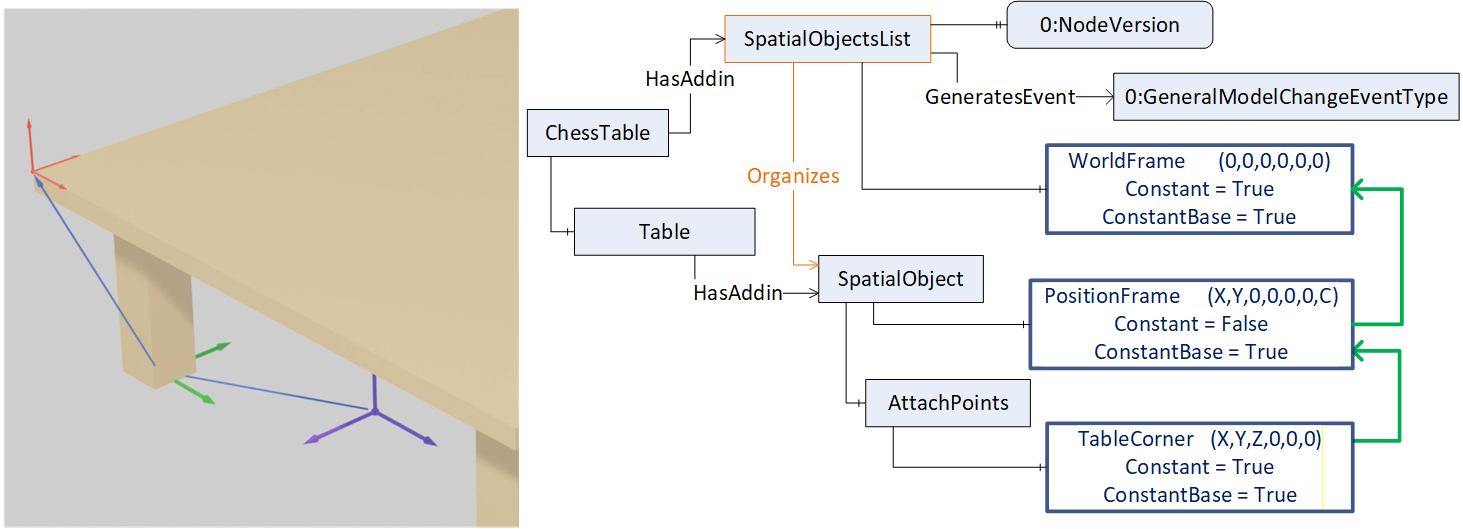
5.2 Introduction with an example of a chess table
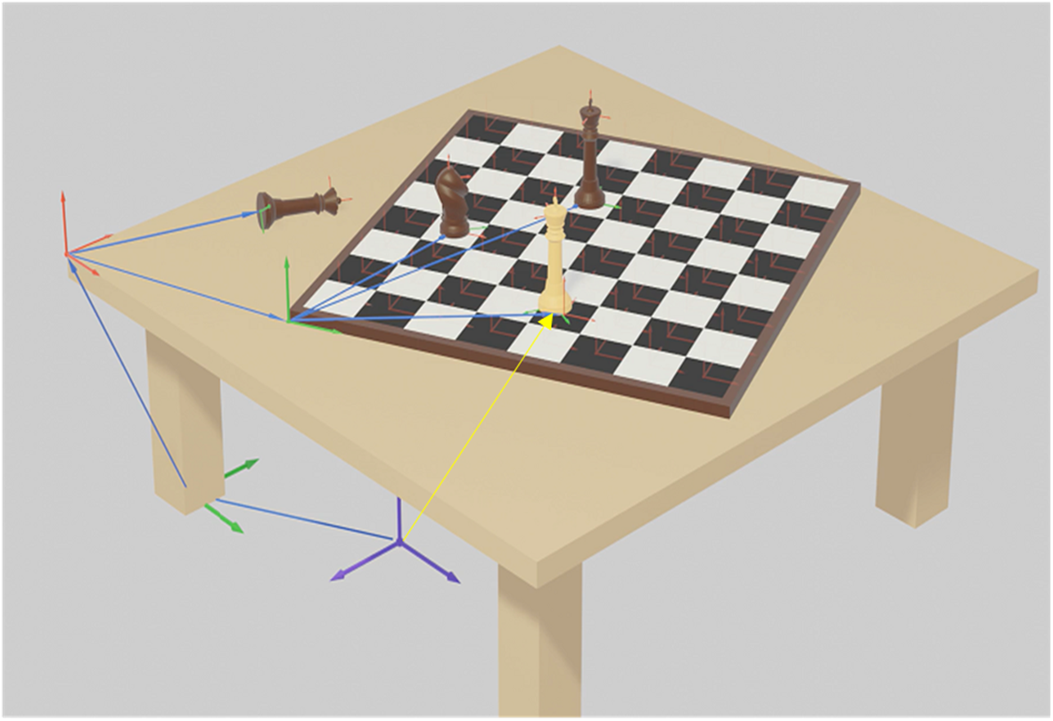
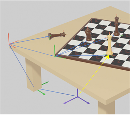
To introduce the RSL concept and the Information Model, the example in Figure 1 has been introduced. It shows an example of objects and their relative spatial locations.
The example shows a table with its location (green coordinate system at the foot of the table) relative to the base coordinate system (blue coordinate system below the table) and a defined attach-point at the corner of the table (red coordinate system) on which a chess board and chess pieces are placed. Other objects can be defined in relation to the attach-point at the corner of the table, such as the brown queen or the chessboard.
For an object (e.g. the chess board) positions (e.g. fields) can be defined as attach-points, which span up coordinate systems where other objects (e.g. chess pieces) can be placed i.e. their positions will be described with respect to the attach-point.
The chess pieces on the board can be related to the chess board or to a field on the board, so changing the position of the board would have no impact on the position of chess pieces, which are related directly or indirectly to the chess board. Changing the position of the table would not impact the relative positions of all those objects, which are directly or indirectly related to the table position.
The yellow arrow describes an alternate frame for the position of the white king, related directly to the base reference coordinate system (blue).
Annex C provides detailed example views for the use of the Relative Spatial Location concept described with this example of a chess board on a table.
5.3 Overview of subtypes of BaseDataVariableType
The RelativeValueType provides a Variable to describe relationship of the Value and is described in 7.1
The SpatialLocationType provides Variables to describe a location and is described in 7.2. The Variable Base shall point to the node, on which this location is based. A subtype of SpatialLocationType is needed to use the Relative Spatial Location AddIns.
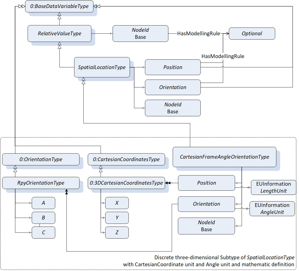
The CartesianFrameAngleOrientationType, described in 7.3, provides a discrete description of a frame, with a position defined by cartesian coordinates and an orientation defined by Euler angles, and unique maths.
Annex E describes how other subtypes of SpatialLocationType can be created and used with ConformanceUnits of the RSL concept.
Figure 3 shows an overview of Relative Spatial Location AddIns by using the CartesianFrameAngleOrientationType as a subtype of the SpatialLocationType and which ConformanceUnits are defined to describe implemented instances.
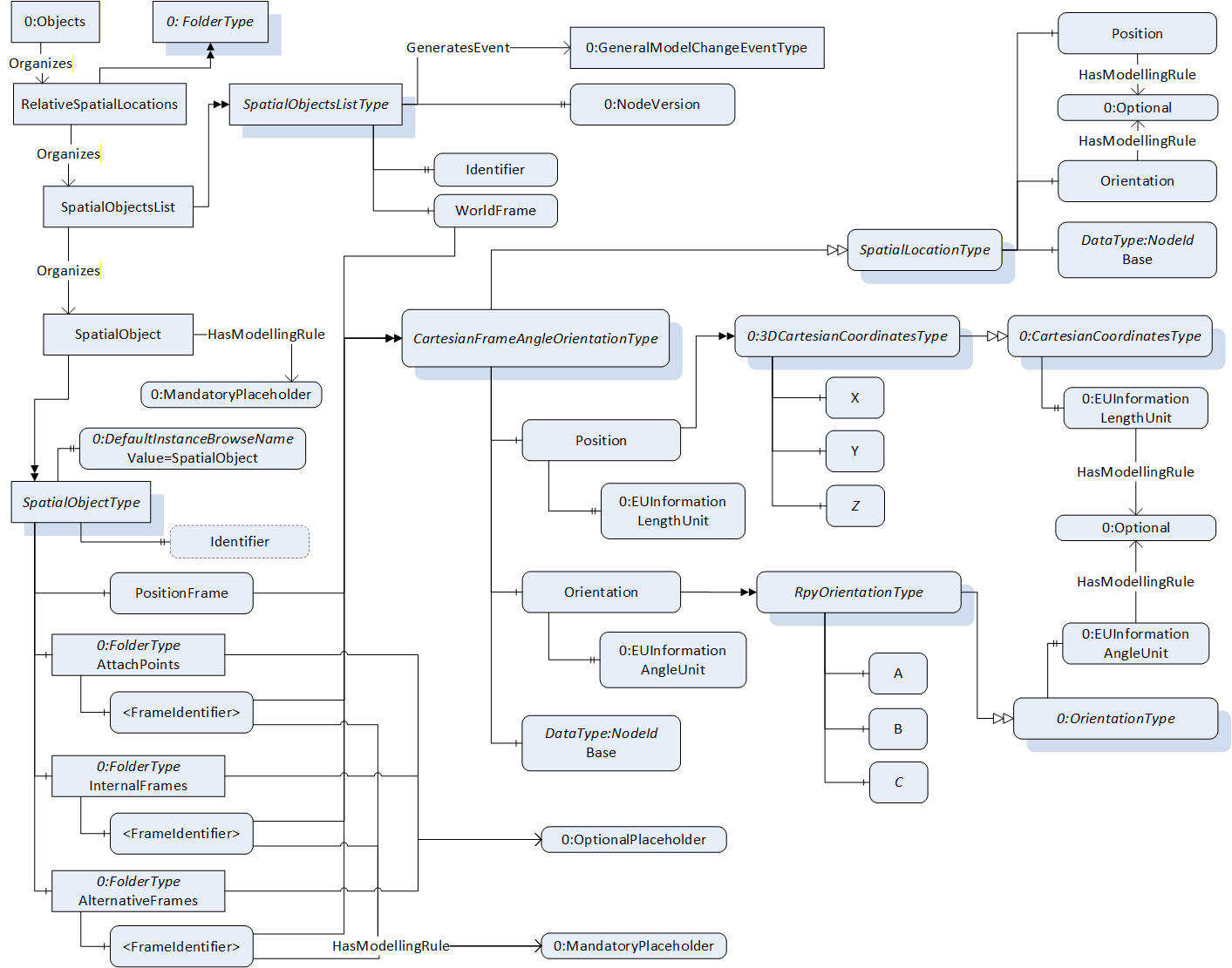
The folder RelativeSpatialLocations, described in 8.1, shall be used to organize all instances of SpatialObjectsListType in one server and may be used as a standard entry point to all type instances described by this model.
The SpatialObjectsListType AddIn, described in 6.2, organizes all instances of SpatialObjectType which are directly or indirectly related to a common coordinate system (WorldFrame). It is recommended to implement in one instance of SpatialObjectsListType only one kind of a discrete subtype instance of SpatialLocationType, e.g., the CartesianFrameAngleOrientationType.
The SpatialObjectType Addin, described in 6.1, can be used to enhance any object in address space with a relative spatial location description.
6 OPC UA ObjectTypes
6.1 SpatialObjectType ObjectType
6.1.1 Overview
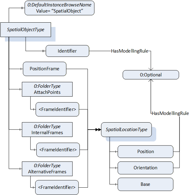
The SpatialObjectType defines an AddIn which can be used to extend objects with a description for relative spatial location.
The SpatialObjectType is illustrated in Figure 4 and is formally defined in Table 12.
| Attribute | Value | ||||
| BrowseName | SpatialObjectType | ||||
| IsAbstract | False | ||||
| References | Node Class | BrowseName | DataType | TypeDefinition | Other |
|---|---|---|---|---|---|
| Subtype of the BaseObjectType defined in OPC 10000-5. | |||||
| 0:HasComponent | Variable | PositionFrame | SpatialLocationType | M | |
| 0:HasComponent | Object | AttachPoints | 0:FolderType | O | |
| 0:HasComponent | Object | InternalFrames | 0:FolderType | O | |
| 0:HasComponent | Object | AlternativeFrames | 0:FolderType | O | |
| 0:HasProperty | Variable | Identifier | 0:String | 0:PropertyType | O |
| 0:HasProperty | Variable | 0:DefaultInstanceBrowseName | 0:QualifiedName | 0:PropertyType | |
| ConformanceUnits | |||||
|---|---|---|---|---|---|
| RSL Base | |||||
| RSL SpatialObject Identifier | |||||
| RSL SpatialObject AttachPoints | |||||
| RSL SpatialObject InternalFrames | |||||
| RSL SpatialObject AlternativeFrames |
The Attribute DisplayName of the SpatialObjectType shall be used to add application specific identification.
The mandatory Variable PositionFrame, describes the local displacement of the object related to the location this displacement is based on. The Variable Base of the SpatialLocationType is used to point to the base location via 0:NodeId.
The optional folder AttachPoints is used to define positions on the object, where other objects can be attached.
The optional folder InternalFrames can be used to define positions or frames, which are of interest for the object, but may not be used as attach points. For example, an internal structure of an object can be described in this folder (see example in Annex C.2).
The optional folder AlternativeFrames can be used to provide additional location information with respect to other coordinate systems described within the same SpatialObjectsList. For example, to provide for an application, a location specific to a coordinate system defined by the application (see example Annex C.1.3).
The optional Property Identifier can be used to name the SpatialObject. For multi-server or aggregating scenarios, the Property Identifier is defined as mandatory by a Facet. (Annex C.3 and C.5 describe examples for the use in different scenarios).
The components of the SpatialObjectType have additional subcomponents which are defined in Table 13.
| BrowsePath | References | NodeClass | BrowseName | DataType | TypeDefinition | Others |
| AttachPoints | 0:HasComponent | Variable | <FrameIdentifier> | BaseDataType | SpatialLocationType | MP |
| InternalFrames | 0:HasComponent | Variable | <FrameIdentifier> | BaseDataType | SpatialLocationType | MP |
| AlternativeFrames | 0:HasComponent | Variable | <FrameIdentifier> | BaseDataType | SpatialLocationType | MP |
The component 0:DefaultInstanceBrowseName of the SpatialObjectType have additional Attributes defined in Table 14.
| BrowsePath | Value Attribute | Description Attribute |
| 0:DefaultInstanceBrowseName | SpatialObject | The default BrowseName for instances of the type. |
6.2 SpatialObjectsListType ObjectType
6.2.1 Overview
The SpatialObjectsListType defines an AddIn which may be used to extend objects with a description for a common identifiable reference coordinate system and Organizes all instances of SpatialObjectType AddIns.
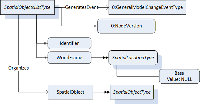
The SpatialObjectsListType is illustrated in Figure 5 and is formally defined in Table 15.
| Attribute | Value | ||||
| BrowseName | SpatialObjectsListType | ||||
| IsAbstract | False | ||||
| References | Node Class | BrowseName | DataType | TypeDefinition | Other |
|---|---|---|---|---|---|
| Subtype of the BaseObjectType defined in OPC 10000-5. | |||||
| 0:HasProperty | Variable | Identifier | 0:String | 0:PropertyType | M |
| 0:HasComponent | Variable | WorldFrame | 0:BaseDataType {Any} | SpatialLocationType | M |
| 0:HasProperty | Variable | 0:NodeVersion | 0:String | 0:PropertyType | M |
| 0:GeneratesEvent | ObjectType | 0:GeneralModelChangeEventType | |||
| 0:Organizes | Object | <SpatialObject> | SpatialObjectType | OP | |
| ConformanceUnits | |||||
|---|---|---|---|---|---|
| RSL Base |
The Attribute DisplayName of the SpatialObjectsListType shall be used to add application specific identification.
The mandatory Property Identifier shall be used to name the SpatialObjectsList. Annex C.3 describes different scenarios for the use of the Identifier.
The mandatory Variable WorldFrame is, direct or indirect via other frames, the geometrical base definition of all objects with SpatialObjectType AddIn, which are OrganizedBy this SpatialObjectsList.
The Variable 0:NodeVersion and the GeneralModelChangeEvent have been added within the SpatialObjectsListType in order to identify changes in the model as described in OPC 10000-3.
A SpatialObjectsList Organizes instances of SpatialObjectType. Typically, a SpatialObjectsList organises at least one instance of SpatialObjectType. Since SpatialObjects are dynamic in nature, it is also possible that no SpatialObject is contained in a SpatialObjectsList.
The components of the SpatialObjectsListType have additional Attributes defined in Table 16.
| BrowsePath | Value Attribute | Description Attribute | ||
| WorldFrame as the origin of the coordinate system has no Base i.e. it must be null. |
7 OPC UA VariableTypes
7.1 RelativeValueType
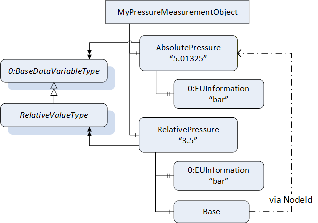
The RelativeValueType is a subtype of the BaseDataVariableType. It is used to inform how values, which are represented by this type, behave, or reference to another value representation.
It is formally defined in Table 17.
| Attribute | Value | |||||
| BrowseName | RelativeValueType | |||||
| IsAbstract | True | |||||
| ValueRank | -2 (Any) | |||||
| DataType | BaseDataType | |||||
| References | NodeClass | BrowseName | DataType | TypeDefinition | Other | |
|---|---|---|---|---|---|---|
| Subtype of the BaseDataVariableType defined in OPC 10000-5 | ||||||
| 0:HasComponent | Variable | Base | 0:NodeId | 0:BaseDataVariableType | O | |
To express if the Value is constant and does not change, the Constant bit of the Attribute AccessLevelEx of the RelativeValueType Variable shall be set to True.
To express if the base (on which the value is based) is constant, the Constant bit of the Attribute AccessLevelEx of the Variable Base shall be set to True.
Figure 6 shows an example usage to the RelativeValueType and the Variable Base.
7.2 SpatialLocationType
The SpatialLocationType is a subtype of the RelativeValueType. It is used for information about position or orientation. A concrete subtype of this abstract type shall be defined for use with the Relative Spatial Location AddIns, e.g., the CartesianFrameAngleOrientationType described in 7.3.
It is formally defined in Table 18.
| Attribute | Value | |||||
| BrowseName | SpatialLocationType | |||||
| IsAbstract | True | |||||
| ValueRank | -2 (Any) | |||||
| DataType | BaseDataType | |||||
| References | NodeClass | BrowseName | DataType | TypeDefinition | Other | |
|---|---|---|---|---|---|---|
| Subtype of the RelativeValueType defined in 7.1 | ||||||
| 0:HasComponent | Variable | Position | 0:BaseDataType | 0:BaseDataVariableType | O | |
| 0:HasComponent | Variable | Orientation | 0:BaseDataType | 0:BaseDataVariableType | O | |
| 0:HasComponent | Variable | Base | 0:NodeId | 0:BaseDataVariableType | M | |
The Variable Position informs about a position. Note that the TypeDefinition is not defined in detail, so it is assumed to define, while subtyping from SpatialLocationType, specific type definitions to provide information about a position e.g., for cartesian, spherical or cylindrical positions.
The Variable Orientation informs about an orientation typically with respect to a position. In mathethamics, orientation defines a geometric notion. For example, in two dimensions it allows to say when a cycle goes clockwise or counterclockwise, or in three dimensions when a figure is left-handed or right-handed. Note that the TypeDefinition is not defined in detail, so it is assumed to define, while subtyping from SpatialLocationType, specific type definitions to provide information about orientation.
The mandatory Variable Base is used to point via NodeId to the location, where the described location is based on.
7.3 CartesianFrameAngleOrientationType
The CartesianFrameAngleOrientationType is a subtype of the SpatialLocationType. It is used for information about frames in 3D space using position representation by cartesian coordinates and orientation representation by Euler angles defined in Annex B.
The CartesianFrameAngleOrientationType is similar as the 3DFrameType, introduced with Amendment 11 and uses the same DataType definition for the position.
For a unique mathematic definition of the orientation calculation the RpyOrientationType is provided.
It is recommended to use this type, instead of 3DFrameType, because of the generic approach of RelativeValueType and SpatialLocationType.
It is formally defined in Table 19.
| Attribute | Value | |||||
| BrowseName | CartesianFrameAngleOrientationType | |||||
| IsAbstract | False | |||||
| ValueRank | -1 (-1 = Scalar) | |||||
| DataType | 3DFrame | |||||
| References | NodeClass | BrowseName | DataType | TypeDefinition | Other | |
|---|---|---|---|---|---|---|
| Subtype of the SpatialLocationType defined in 7.2 | ||||||
| 0:HasComponent | Variable | Position | 0:3DCartesianCoordinates | 0:3DCartesianCoordinatesType | M | |
| 0:HasComponent | Variable | Orientation | 0:3DOrientation | RpyOrientationType | M | |
| ConformanceUnits | ||||||
|---|---|---|---|---|---|---|
| CartesianFrameAngleOrientationType |
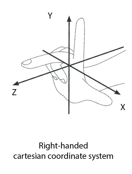
The Variable Position is defined as 3DCartesianCoordinatesType, which includes the lengths X, Y and Z, to represent a three-dimensional cartesian position. It shall apply to the right-handed coordinate system definition defined in Annex B.
The Variable Orientation is defined as RpyOrientationType, defined in 7.4, which includes the angles A, B and C to represent the rotations about the axes of the cartesian coordinate system. It shall apply to the mathematic definition described in Annex B.
The components of the CartesianFrameAngleOrientationType have additional subcomponents which are defined in Table 20.
| BrowsePath | References | NodeClass | BrowseName | DataType | TypeDefinition | Others |
| Position | 0:HasProperty | Variable | 0:LengthUnit | 0:EUInformation | PropertyType | M |
| Orientation | 0:HasProperty | Variable | 0:AngleUnit | 0:EUInformation | PropertyType | M |
7.4 RpyOrientationType
The RpyOrientationType is a subtype of the 0:OrientationType. It is used for information about the orientation of coordinate systems in three-dimensional space using Euler angles uniquely defined in Annex B by the roll-pitch-yaw definition (intrinsic rotations z-y'-x").
It is formally defined in Table 21.
| Attribute | Value | |||||
| BrowseName | RpyOrientationType | |||||
| IsAbstract | False | |||||
| ValueRank | -1 (-1 = Scalar) | |||||
| DataType | 3DOrientation | |||||
| References | NodeClass | BrowseName | DataType | TypeDefinition | Other | |
|---|---|---|---|---|---|---|
| Subtype of the OrientationType defined in OPC 10000-5 | ||||||
| 0:HasComponent | Variable | A | 0:Double | 0:BaseDataVariableType | M | |
| 0:HasComponent | Variable | B | 0:Double | 0:BaseDataVariableType | M | |
| 0:HasComponent | Variable | C | 0:Double | 0:BaseDataVariableType | M | |
| ConformanceUnits | ||||||
|---|---|---|---|---|---|---|
| CartesianFrameAngleOrientationType |
8 Instances
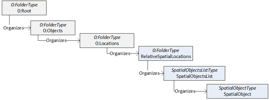
8.1 RelativeSpatialLocations Definition
The RelativeSpatialLocations Object is a standardized entry point to access all SpatialObjectsLists managed in the Server and is illustrated in Figure 7 and formally defined in Table 22.
Since later versions of this specification might change the parent of this Object, Clients aware of this standardized Object shall not access it via its parent but directly via its standardized NodeId.
| Attribute | Value | |||
| BrowseName | RelativeSpatialLocations | |||
| References | NodeClass | BrowseName | DataType | TypeDefinition |
|---|---|---|---|---|
| OrganizedBy by the 0:Locations defined in OPC 10000-5 | ||||
| 0:HasTypeDefinition | ObjectType | 0:FolderType | Defined in OPC 10000-5 | |
| ConformanceUnits | ||||
|---|---|---|---|---|
| RSL Base |
To identify all SpatialObjectsLists inside a Server the referenced Objects are representations of SpatialObjectsListType.
The RelativeSpatialLocations Object shall be referenced from the 0:Locations Object defined in OPC 10000-5 with an Organizes Reference.
9 Profiles and Conformance Units
9.1 Conformance Units
Table 23 defines the corresponding ConformanceUnits for the OPC UA Information Model for RSL.
| Category | Title | Description |
| Server | RSL Base | Supports the base functionality defined in RSL InformationModel with at least one instance of SpatialObjectsListType (6.2) organized by the RelativeSpatialLocations object. The SpatialObjectsListType instance shall support at least one instance of SpatialObjectType (6.1). The Variable PositionFrame of the SpatialObjectType instance shall be of a discrete subtype of SpatialLocationType (7.2) |
| Server | RSL SpatialObject Identifier | Supports the variable Identifier of SpatialObjectType (6.1). |
| Server | RSL SpatialObject AttachPoints | Supports the folder AttachPoints of SpatialObjectType (6.1). |
| Server | RSL SpatialObject InternalFrames | Supports the folder InternalFrames of SpatialObjectType (6.1). |
| Server | RSL SpatialObject AlternativeFrames | Supports the folder AlternativeFrames of SpatialObjectType (6.1). |
| Server | CartesianFrameAngleOrientationType | Instances of SpatialObjectType use the CartesianFrameAngleOrientationType (7.3) for WorldFrame and PositionFrame |
| Client | RSL Client Base | Consumes the Object RelativeSpatialLocations (8.1) and Objects that conform to the types SpatialObjectType (6.1), SpatialObjectsListType (6.2) (described with sequences in Annex D.1) and interpret provided location information (e.g. following the reference chains to find the world frame) |
| Client | RSL Client ModelChange | Receives the ModelChangeEvent or subscribes to the NodeVersion property and updates the model related information in its use-cases (e.g. rebrowse of the address space) |
9.2 Profiles
9.2.1 Profile list
Table 24 lists all Profiles defined in this document and defines their URIs.
| Profile | URI |
| RSL CartesianFrameAngleOrientation Profile | http://opcfoundation.org/UA-Profile/RSL/Server/ CartesianFrameAngleOrientation |
RSL CartesianFrameAngleOrientation Identifier Profile | http://opcfoundation.org/UA-Profile/RSL/Server/ CartesianFrameAngleOrientationIdentifier |
9.2.2 Server Facets
9.2.2.1 Overview
The following sections specify the Facets available for Servers that implement the RSL companion specification. Each section defines and describes a Facet or Profile.
9.2.2.2 RSL CartesianFrameAngleOrientation Profile
Table 25 defines a Profile that describes the base functionality of RSL information model using the CartesianFrameAngleOrientationType.
| Group | Conformance Unit / Profile Title | Mandatory / Optional |
| Address Space Model | 0:Address Space Base | M |
| Address Space Model | 0:Address Space AddIn Reference | M |
| Address Space Model | 0:Address Space AddIn DefaultInstanceBrowsename | M |
| View Services | 0:View Basic | M |
| View Services | 0:View TranslateBrowsePath | M |
| View Services | 0:View Minimum Continuation Point 01 | M |
| Attribute Services | 0:Attribute Read | M |
| RSL | RSL Base | M |
| RSL | CartesianFrameAngleOrientationType | M |
| RSL | RSL SpatialObject AttachPoints | O |
| RSL | RSL SpatialObject InternalFrames | O |
| RSL | RSL SpatialObject AlternativeFrames | O |
9.2.2.3 RSL CartesianFrameAngleOrientation Identifier Profile
Table 26 defines a Facet that describes the additionally to the base functionality of RSL information model using the CartesianFrameAngleOrientationType the Identifier Property SpatialObjects.
| Group | Conformance Unit / Profile Title | Mandatory / Optional |
| Profile | RSL CartesianFrameAngleOrientation Profile | M |
| RSL | RSL SpatialObject Identifier | M |
9.2.3 Client Facets
9.2.3.1 Overview
The following tables specify the Facets available for Clients that implement the Relative Spatial Location companion specification.
9.2.3.2 RSL Base Client Profile
Table 27 defines a Facet that describes the base characteristics for all OPC UA Clients that make use of this companion specification. Additional Profiles will define support for various information models that are part of this document.
| Group | Conformance Unit / Profile Title | Mandatory / Optional |
| Profile | 0:AddressSpace Lookup Client Facet http://opcfoundation.org/UA-Profile/Client/AddressSpaceLookup | |
| Profile | 0:DataAccess Client Facet http://opcfoundation.org/UA-Profile/Client/DataAccess | |
| Profile | 0:DataChange Subscriber Client Facet http://opcfoundation.org/UA-Profile/Client/DataChangeSubscriber | |
| Session Services | 0:Session Client Detect Shutdown | M |
| RSL | RSL Client Base | M |
| RSL | RSL Client ModelChange | O |
10 Namespaces
10.1 Namespace Metadata
Table 28 defines the namespace metadata for this document. The Object is used to provide version information for the namespace and an indication about static Nodes. Static Nodes are identical for all Attributes in all Servers, including the Value Attribute. See OPC 10000-5 for more details.
The information is provided as Object of type NamespaceMetadataType. This Object is a component of the Namespaces Object that is part of the Server Object. The NamespaceMetadataType ObjectType and its Properties are defined in OPC 10000-5.
The version information is also provided as part of the ModelTableEntry in the UANodeSet XML file. The UANodeSet XML schema is defined in OPC 10000-6.
| Attribute | Value | ||
| BrowseName | http://opcfoundation.org/UA/RSL/ | ||
| Property | DataType | Value | |
|---|---|---|---|
| NamespaceUri | String | http://opcfoundation.org/UA/RSL/ | |
| NamespaceVersion | String | 1.00.1 | |
| NamespacePublicationDate | DateTime | 2023-01-12 | |
| IsNamespaceSubset | Boolean | False | |
| StaticNodeIdTypes | IdType [] | ||
| StaticNumericNodeIdRange | NumericRange [] | ||
| StaticStringNodeIdPattern | String | ||
10.2 Handling of OPC UA Namespaces
Namespaces are used by OPC UA to create unique identifiers across different naming authorities. The Attributes NodeId and BrowseName are identifiers. A Node in the UA AddressSpace is unambiguously identified using a NodeId. Unlike NodeIds, the BrowseName cannot be used to unambiguously identify a Node. Different Nodes may have the same BrowseName. They are used to build a browse path between two Nodes or to define a standard Property.
Servers may often choose to use the same namespace for the NodeId and the BrowseName. However, if they want to provide a standard Property, its BrowseName shall have the namespace of the standards body although the namespace of the NodeId reflects something else, for example the EngineeringUnits Property. All NodeIds of Nodes not defined in this document shall not use the standard namespaces.
Table 29 provides a list of mandatory and optional namespaces used in an RSL OPC UA Server.
| NamespaceURI | Description | Use |
| http://opcfoundation.org/UA/ | Namespace for NodeIds and BrowseNames defined in the OPC UA specification. This namespace shall have namespace index 0. | Mandatory |
| Local Server URI | Namespace for nodes defined in the local server. This namespace shall have namespace index 1. | Mandatory |
| http://opcfoundation.org/UA/DI/ | Namespace for NodeIds and BrowseNames defined in OPC 10000-100. The namespace index is Server specific. | Optional |
| http://opcfoundation.org/UA/RSL/ | Namespace for NodeIds and BrowseNames defined in this document. The namespace index is Server specific. | Mandatory |
| Vendor specific types | A Server may provide vendor-specific types like types derived from ObjectTypes defined in this document in a vendor-specific namespace. | Optional |
| Vendor specific instances | A Server provides vendor-specific instances of the standard types or vendor-specific instances of vendor-specific types in a vendor-specific namespace. It is recommended to separate vendor specific types and vendor specific instances into two or more namespaces. | Mandatory |
Table 30 provides a list of namespaces and their indices used for BrowseNames in this document. The default namespace of this document is not listed since all BrowseNames without prefix use this default namespace.
| NamespaceURI | Namespace Index | Example |
| http://opcfoundation.org/UA/ | 0 | 0:EngineeringUnits |
| http://opcfoundation.org/UA/DI/ | 2 | 2:DeviceRevision |
Annex A Relative Spatial Location Namespace and mappings (Normative)
A.1 Namespace and identifiers for Relative Spatial Location Information Model
This appendix defines the numeric identifiers for all of the numeric NodeIds defined in this document. The identifiers are specified in a CSV file with the following syntax:
<SymbolName>, <Identifier>, <NodeClass>Where the SymbolName is either the BrowseName of a Type Node or the BrowsePath for an Instance Node that appears in the specification and the Identifier is the numeric value for the NodeId.
The BrowsePath for an Instance Node is constructed by appending the BrowseName of the instance Node to the BrowseName for the containing instance or type. An underscore character is used to separate each BrowseName in the path. Let's take for example, the SpatialObjectType ObjectType Node which has the Identifier Property. The Name for the Identifier InstanceDeclaration within the SpatialObjectType declaration is: SpatialObjectType_Identifier.
The NamespaceUri for all NodeIds defined here is http://opcfoundation.org/UA/RSL/
The CSV released with this version of the specification can be found here:
http://www.opcfoundation.org/UA/schemas/RSL/1.0/NodeIds.csv
http://www.opcfoundation.org/UA/schemas/RSL/NodeIds.csv
A computer processible version of the complete Information Model defined in this document is also provided. It follows the XML Information Model schema syntax defined in OPC 10000-6.
The Information Model Schema for this version of the document (including any revisions, amendments or errata) can be found here:
http://www.opcfoundation.org/UA/schemas/RSL/1.0/Opc.Ua.RSL.NodeSet2.xml
http://www.opcfoundation.org/UA/schemas/RSL/Opc.Ua.RSL.NodeSet2.xml
_____________
Annex B Maths Definition for CartesianCoordinateAngleOrientationType (Normative)
The position and orientation of objects in space is a general requirement that will be needed also by other companion specifications. Thus, we try to establish a general description.
B.1 Three-dimensional cartesian coordinates apply to right-hand rule
B.2 Definition of rotations defined by orientation angles
A frame describes the translation and rotation of an object relative to another frame (the base frame). Figure 9 shows a simple frame chain to clarify the notation. The frame A is the base of frames B and C. The frames B and C are based on frame A. Frame C is the base of frames D and E. The frames D and E are based on frame C.
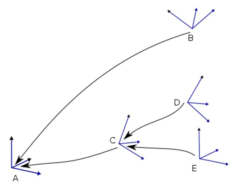
As shown in Figure 9 an arrow points from a frame to its base frame to visualize the frame chains. This arrow can be read as "The coordinates of frame B are specified in (or relative to) Frame A". In addition to the coordinates of frame B you also need to know its base frame A.
The coordinates of a frame are represented by the three values P = (X, Y, Z) for the position and the three values O = (A, B, C) for the orientation.
P is the translation relative to the base frame. When the translation of a frame is 0 then the origins of the frame and its base frame coincide.
O is the orientation of the frame in yaw, pitch and roll notation (see also ISO 9787:2013 "Robots and robotic devices - Coordinate systems and motion nomenclatures" or Wikipedia article about Euler angles)
We use the notation of pre-multiplying rotation-matrices and column vectors.
Figure 10 shows the three elementary rotations A, B and C as specified in ISO 9787:2013.
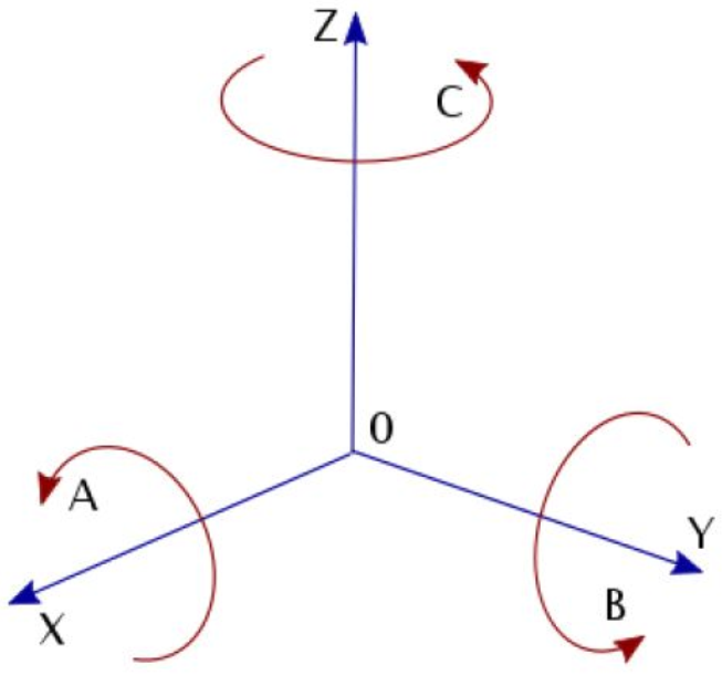
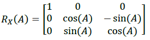
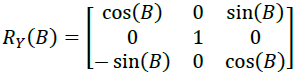
The elementary rotations correspond to the following rotation matrices:
A = roll = rotation about X axis
B = pitch = rotation about Y axis
C = yaw = rotation about Z axis
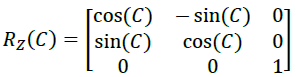
ISO 9787:2013 does not define the order of the rotations or the whether to use intrinsic or extrinsic rotations. Thus, we refer to the Wikipedia article here. It says that the intrinsic rotations z-y'-x" are known as yaw, pitch and roll, giving the transformation matrix
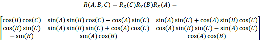
Figure 11 shows the three consecutive rotations:
1. Rotation about the Z axis (blue rotation; blue frame à green frame)
2. Rotation about the new Y axis (green rotation; green frame à red frame)
3. Rotation about the new X axis (red rotation; red frame à black frame)
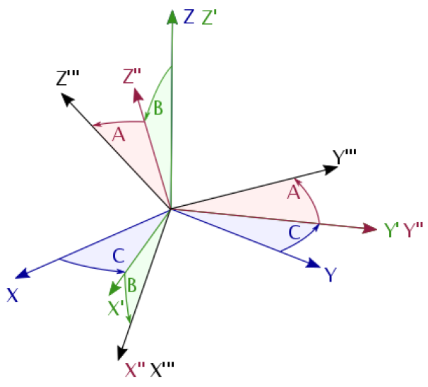
The extrinsic rotations x-y-z about the axis of the original fixed coordinate system result in the same transformation matrix. This is
1. Rotation about the X axis
2. Rotation about the original Y axis
3. Rotation about the original Z axis
Annex C Relative Spatial Location examples (Informative)
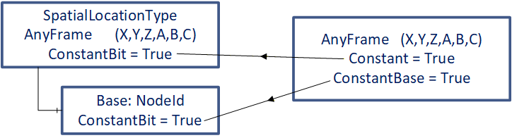
To show usage of the Constant bit of the Attribute AccessLevelEx, which provides the information about dynamic or static behavior, the figures in Annex C are simplified in the following way (see Figure 12) :
"Constant" is used for the Constant bit of the AccessLevelEx Attribute of the Variable itself
"ConstantBase" is used for the Constant bit of the AccessLevelEx Attribute of the Variable Base
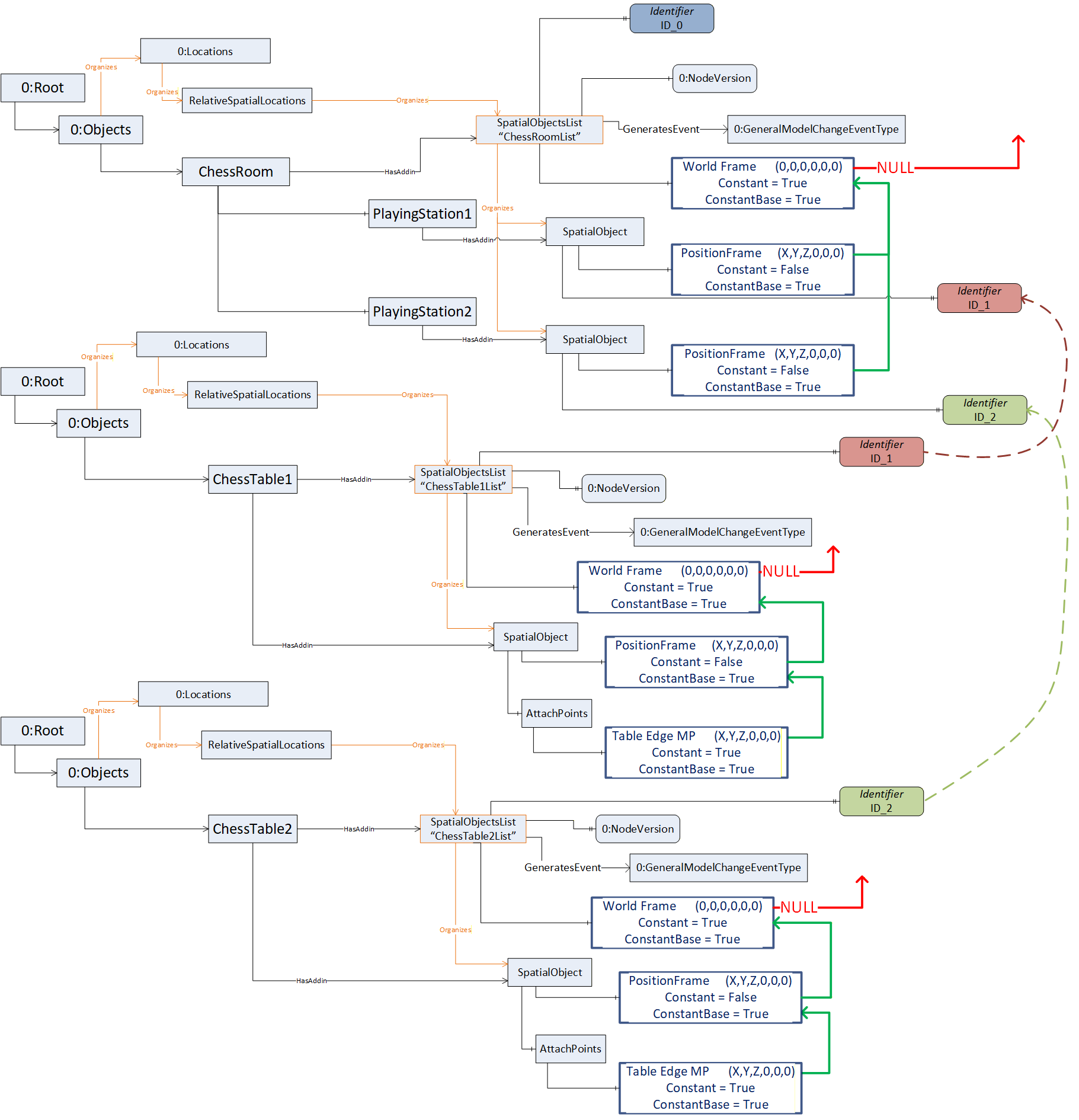
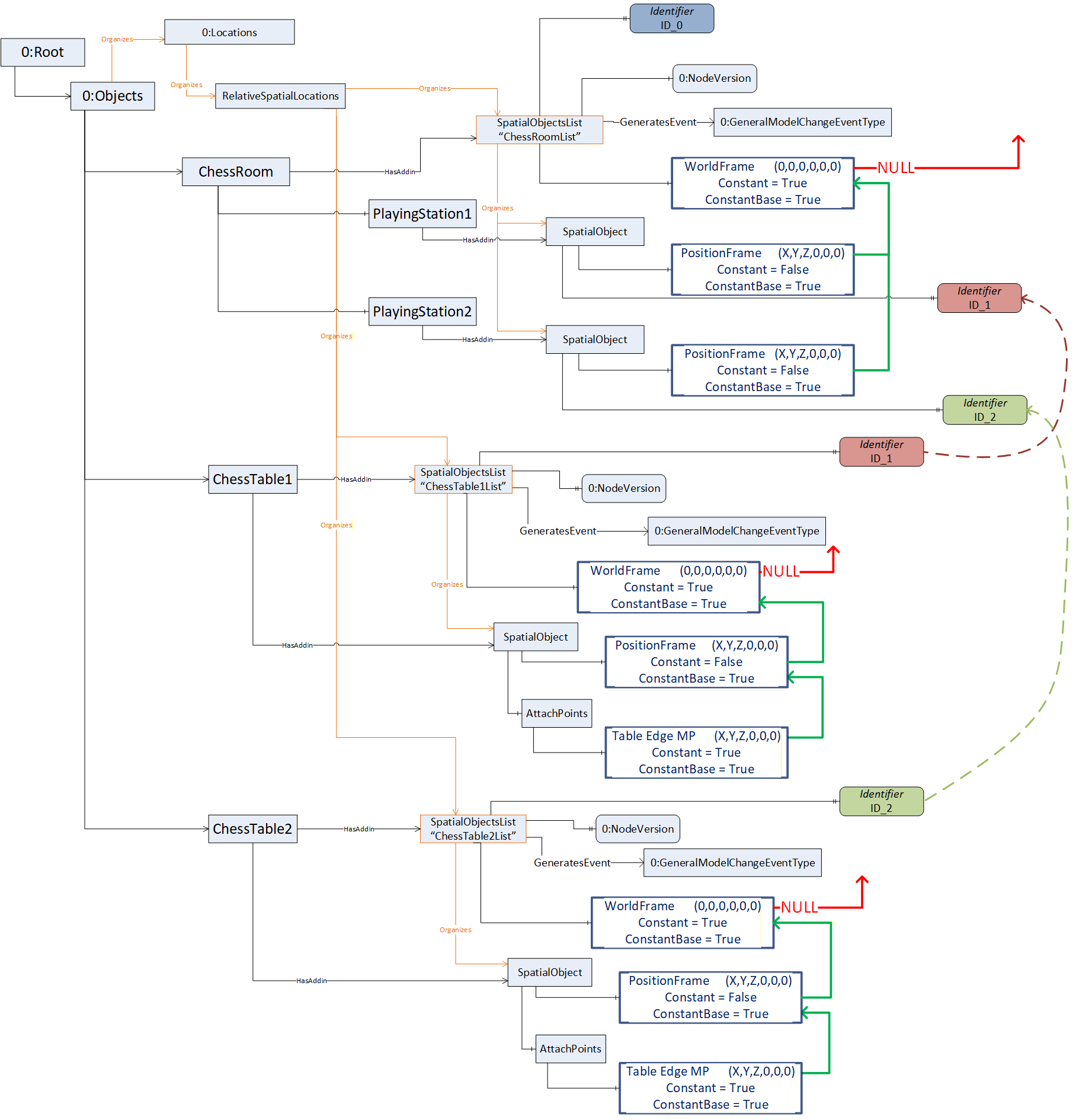
C.1 Example ChessTable
Remark: The Variable Base of instances of SpatialLocationType are shown in the server-instance-examples as green arrows (acting as poor-mans-references) between the instances of CartesianFrameAngleOrientationType, which describe frames.
In the rendered images green coordinate systems define the positions of objects and red coordinate systems define attach points which could be added to objects. The base coordinate-system (WorldFrame) is blue.
C.1.1 Each object in space is self-contained - example: Table
An object is extended by the SpatialObject-Addin which provides (see Figure 13):
Its position regarding a defined coordinate system (WorldFrame):
The green coordinate system at the left foot of the table is the location of the table. It is defined by the PositionFrame of its SpatialObject, which describes the shift related to the WorldFrame.
It is assumed that the table is movable, so the Property Constant this PositionFrame is False. This table is moveable but will always be related to this WorldFrame, so ConstantBase of this PositionFrame is True.
Attach points of the object where other objects can be geometrically related:
The red coordinate system at the table corner can be defined as an attach-point of the table.
The blue arrow from the foot to the corner of the table shows the displacement (via a frame definition) from the table position to the table corner by the frame TableCorner. The red coordinate system defines the coordinate system of this attach point.
The table is rigid, so table corner does not change its position and so Constant and ConstantBase of this attach-point TableCorner are both True.
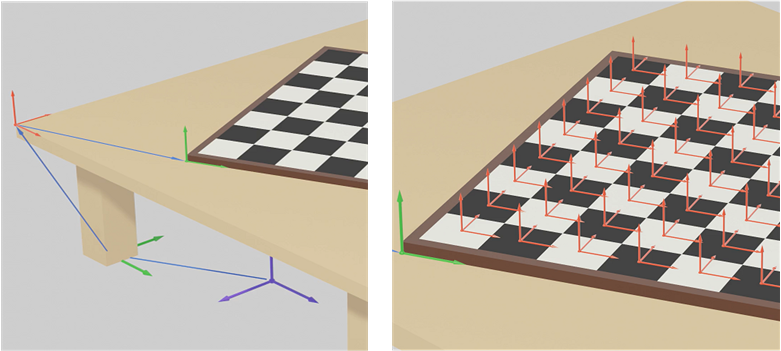
C.1.2 Attach an object to another object - example: Table with chess board with fields
The chess board is an own object (extended with the SpatialObjectType Addin) and is geometrically described with
its position regarding the attach-point of the table (TableCorner) by its PositionFrame.
We assume that the chess board can be moved to another object (e.g. another table), so ConstantBase of the PositionFrame of the Chessboard is False.
We assume that the chess board can be displaced on this table, so the Constant of this frame is False.
And the chess board can be brought in relationship to any other object, so the ConstantBase of this frame is False. So, if this chess board should be only moved on the table it might be hard related the table corner, so the ConstantBase would be True.
possible attach-points of the chess board. All field center positions (red coordinate systems on the right picture in Figure 14) can be described individually (xxCenterAP frames in Figure 15 where xx indicates the field number).
based on the common coordinate system of the chess board (green coordinate system which is described by the chess board PositionFrame relative to the table corner)
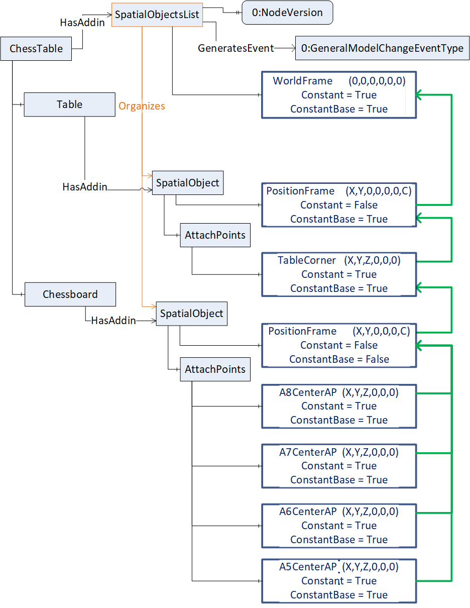
C.1.3 Attaching further objects - example: chess pieces on a field of the chess table
The brown knight piece is an own object (extended with the SpatialObjectType Addin) placed on field D7 (Figure 16), is positioned to the coordinate system of field D7 (red coordinate system) by a rotation of angle C counterclockwise in its position frame. (green coordinate system on field C7).
The head of the brown knight piece can be defined as own attach-point, of the figure because this might be a position to pick up this object.
An alternative frame for describing the position of the brown knight provides the knight´s position additionally related to the chess board position (PosToBoard based on the green coordinate system spanned up by the chess board´s PositionFrame).
For this example, the Properties of the PositionFrame of the brown knight are defined as:
ConstantBase = False, because when the knight is moved to another field the Base may change to the new field.
Constant = False, because the position and orientation relative to any Base will most likely change with every move.
C.1.4 Attaching further objects with and without attach-points - example: Chess board on table with chess pieces.
Note, that the chess pieces on the board are related directly to the chess board and not to fields of the chess board to show the flexibility of this concept.
In this example (Figure 17) there are no fields on a chess board defined as attach-points. So, the pieces on the board are related directly to the position of the board. So, the position frames of the brown horse, the brown king and the white king include the shift of X, Y and Z additionally to the rotation C (compared to example C.1.3 using attach points for fields of a chess board).
The PositionFrame of the brown queen is related to the attach point of the table corner
The white king has an alternative position frame (WorldPosWK yellow) related to the WorldFrame.
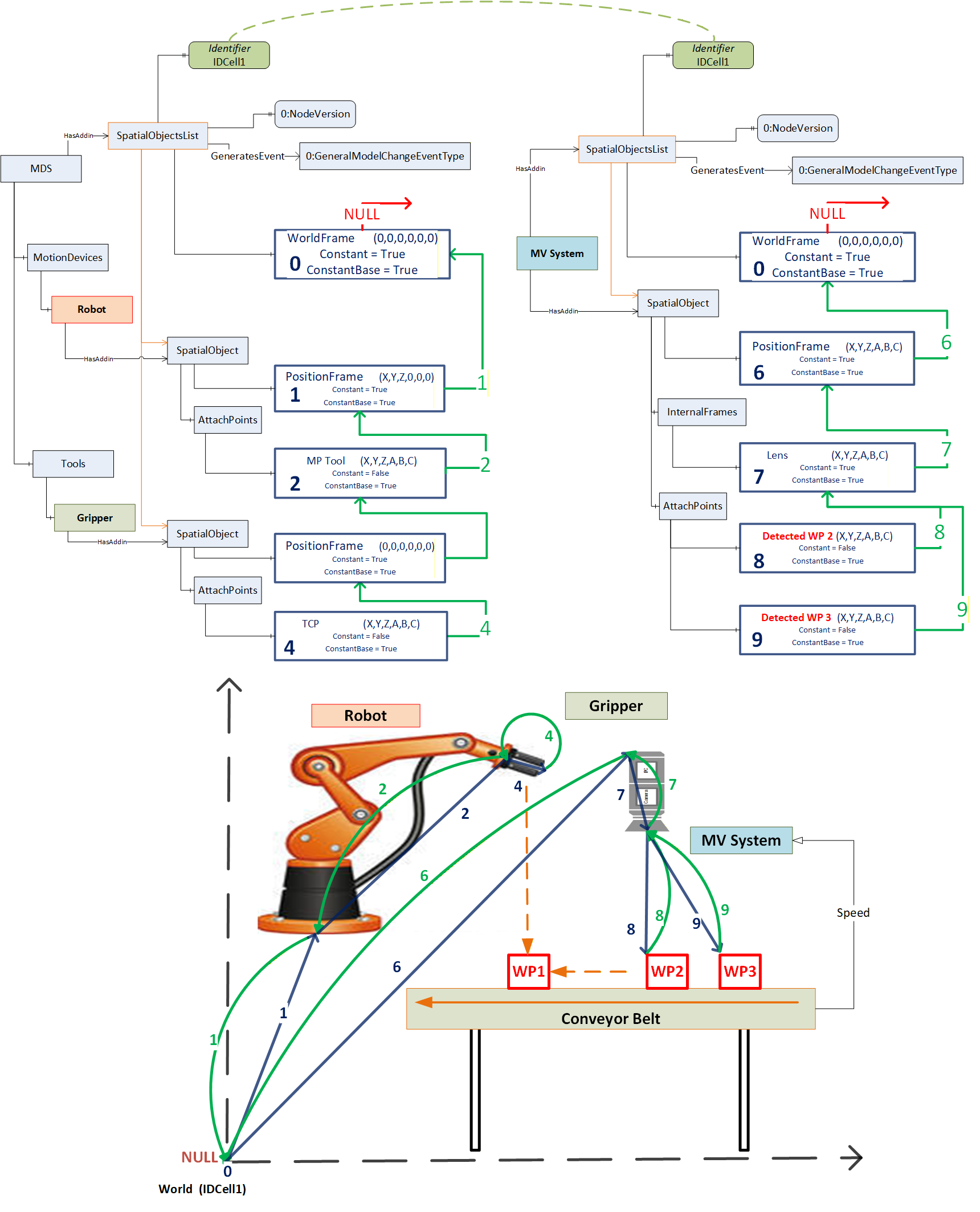
C.2 Example of two motion devices with tools
Following example address space describes the Spatial Relative Location concept with different objects used in an example industrial application (Figure 18). A robot mounted on a linear unit carrying an exchangeable robot tool. A second tool to change is placed at a change station on a table. Additionally, a tool for the robot is configured and not used in this application scenario (so Variable Base is NULL), but may occur, when brought in spatial relationship to frames SpatialObjects of this SpatialObjectsList.
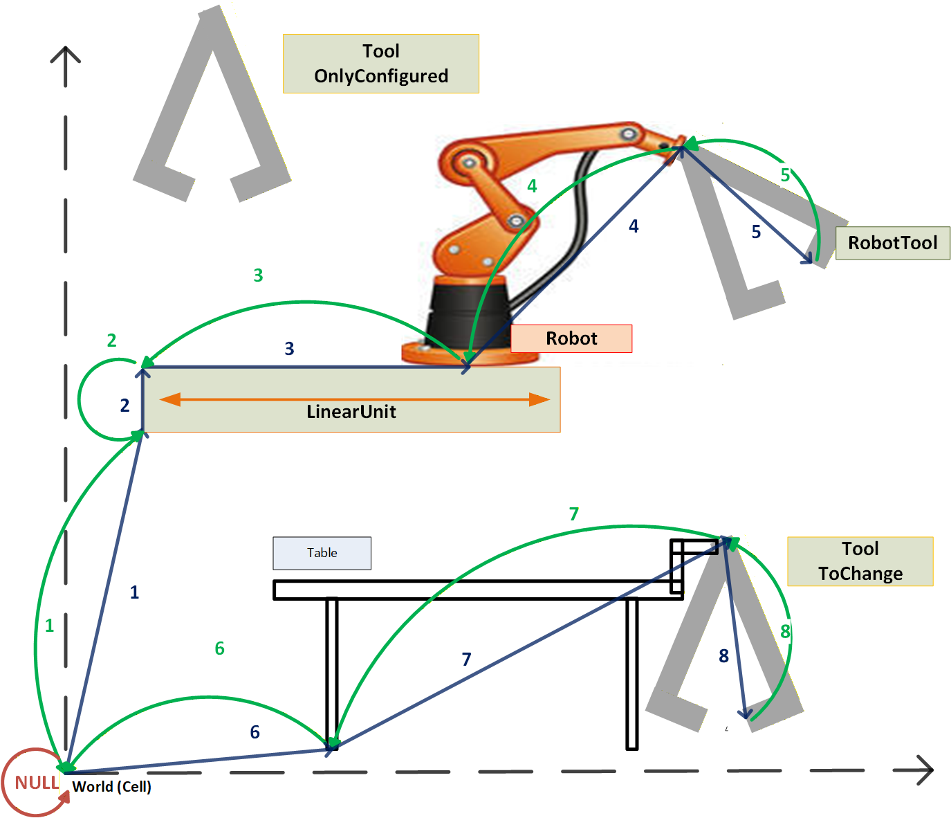
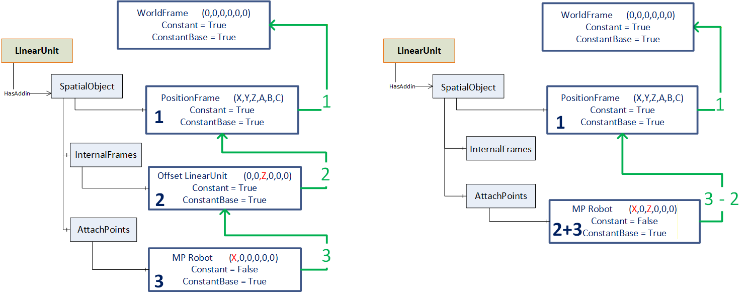
Following figure (Figure 19) shows different representations how, for example, the SpatialObject of the LinearUnit can be described
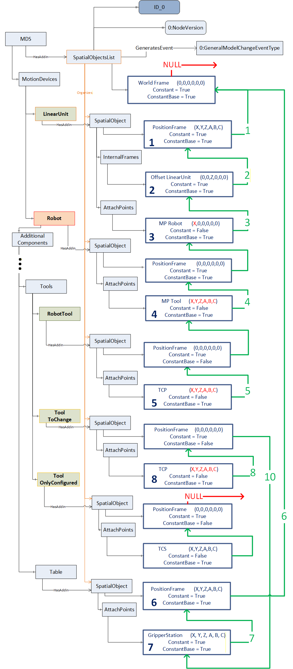
Following figure (Figure 20) shows an example address space for an automation cell as shown in Figure 18
C.3 Example use of the Identifier Property in a multi-server scenario
For the use in multi-server scenarios with different servers it might be needed to identify all related SpatialObjectsLists and bring them in relationship in a higher levelled SpatialObjectsList. For this the Property Identifier of a SpatialObjectsList can be instantiated as the Property Identifier of a SpatialObject contained in a higher-level SpatialObjectsList.
C.4 Example use of the Identifier Property in aggregated scenarios
Figure 22 shows an aggregating server, which aggregates all servers illustrated in Figure 21.
C.5 Example usage of the Property Identifier in applications running on different servers
A lot of devices within an automation cell are running geometrically based on a common base frame definition.
At the setup of the automation-cell the Property Identifier might be used for a common cell-id to support the usage of the Relative Spatial Location concept in different devices using a common base coordinate system (Figure 23).
Annex D Client Server Sequences (Informative)
D.1 Example Client Server sequence flow using the RSL concept
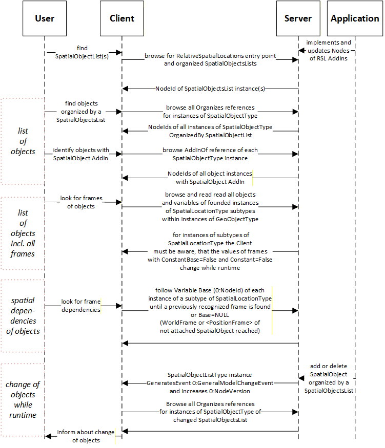
The entities represented in the above sequence diagram (Figure 24) are as follows:
Application : The application that provides the relative spatial location information to the OPC UA Server that exposes the elements with this information.
Server : The OPC UA Server exposing the nodes with the relative spatial location information in its address space.
Client : The OPC UA Client that accesses the information exposed by the aforementioned server by using the OPC UA Services provided by the server.
User : The consumer application that uses the OPC UA Client (mentioned above).
Annex E Subtyping of SpatialLocationType (Informative)
E.1 Example of subtyping SpatialLocationType using the RSL concept
For the use of the RSL concept it is needed to create a subtype of SpatialLocationType (7.2). Very common in use in factory automation is to use cartesian positions and euler angles to describe relative spatial relationships, as defined by CartesianFrameAngleOrientationType (7.3).
To describe relative spatial relationships another format or math might be needed to represent a position (e.g., in polar or cylindrical coordinates) or an orientation (e.g., in quaternion).
Figure 25 shows exemplary how other specific subtypes of SpatialLocationType (7.2) can be created. For example, a CartesianFrameQuaternionOrientationType, which can use the Variable Position in the same way the CartesianFrameAngleOrientationType uses it and describes Orientation with Quaternion. Or for representations without orientation only Types which provide a Position (e.g. the CylindricalCoordinatesFrameType or the PolarCoordinatesFrameType).
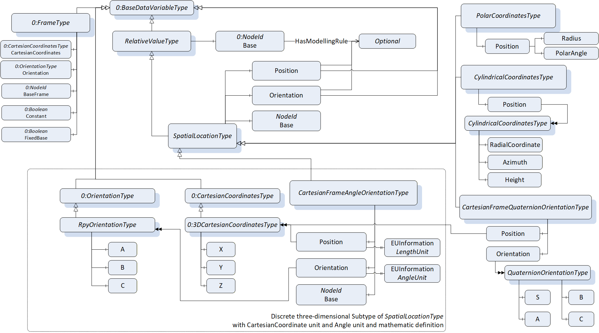
By describing a ConformanceUnit (similar to the CartesianFrameAngleOrientationType ConformanceUnit) for a created subtype of SpatialLocationType and combining this with ConformanceUnits of the RSL concept, as defined in the RSL CartesianFrameAngleOrientation Profile (9.2.2.2), new Profiles can be created to represent spatial relationships in other formats.
Agreement of Use
COPYRIGHT RESTRICTIONS
Any unauthorized use of this specification may violate copyright laws, trademark laws, and communications regulations and statutes. This document contains information which is protected by copyright. All Rights Reserved. No part of this work covered by copyright herein may be reproduced or used in any form or by any means--graphic, electronic, or mechanical, including photocopying, recording, taping, or information storage and retrieval systems--without permission of the copyright owner.
OPC Foundation members and non-members are prohibited from copying and redistributing this specification. All copies must be obtained on an individual basis, directly from the OPC Foundation Web site http://www.opcfoundation.org.
PATENTS
The attention of adopters is directed to the possibility that compliance with or adoption of OPC specifications may require use of an invention covered by patent rights. OPC shall not be responsible for identifying patents for which a license may be required by any OPC specification, or for conducting legal inquiries into the legal validity or scope of those patents that are brought to its attention. OPC specifications are prospective and advisory only. Prospective users are responsible for protecting themselves against liability for infringement of patents.
WARRANTY AND LIABILITY DISCLAIMERS
WHILE THIS PUBLICATION IS BELIEVED TO BE ACCURATE, IT IS PROVIDED "AS IS" AND MAY CONTAIN ERRORS OR MISPRINTS. THE OPC FOUDATION MAKES NO WARRANTY OF ANY KIND, EXPRESSED OR IMPLIED, WITH REGARD TO THIS PUBLICATION, INCLUDING BUT NOT LIMITED TO ANY WARRANTY OF TITLE OR OWNERSHIP, IMPLIED WARRANTY OF MERCHANTABILITY OR WARRANTY OF FITNESS FOR A PARTICULAR PURPOSE OR USE. IN NO EVENT SHALL THE OPC FOUNDATION BE LIABLE FOR ERRORS CONTAINED HEREIN OR FOR DIRECT, INDIRECT, INCIDENTAL, SPECIAL, CONSEQUENTIAL, RELIANCE OR COVER DAMAGES, INCLUDING LOSS OF PROFITS, REVENUE, DATA OR USE, INCURRED BY ANY USER OR ANY THIRD PARTY IN CONNECTION WITH THE FURNISHING, PERFORMANCE, OR USE OF THIS MATERIAL, EVEN IF ADVISED OF THE POSSIBILITY OF SUCH DAMAGES.
The entire risk as to the quality and performance of software developed using this specification is borne by you.
RESTRICTED RIGHTS LEGEND
This Specification is provided with Restricted Rights. Use, duplication or disclosure by the U.S. government is subject to restrictions as set forth in (a) this Agreement pursuant to DFARs 227.7202-3(a); (b) subparagraph (c)(1)(i) of the Rights in Technical Data and Computer Software clause at DFARs 252.227-7013; or (c) the Commercial Computer Software Restricted Rights clause at FAR 52.227-19 subdivision (c)(1) and (2), as applicable. Contractor / manufacturer are the OPC Foundation, 16101 N. 82nd Street, Suite 3B, Scottsdale, AZ, 85260-1830.
COMPLIANCE
The OPC Foundation shall at all times be the sole entity that may authorize developers, suppliers and sellers of hardware and software to use certification marks, trademarks or other special designations to indicate compliance with these materials. Products developed using this specification may claim compliance or conformance with this specification if and only if the software satisfactorily meets the certification requirements set by the OPC Foundation. Products that do not meet these requirements may claim only that the product was based on this specification and must not claim compliance or conformance with this specification.
Trademarks
Most computer and software brand names have trademarks or registered trademarks. The individual trademarks have not been listed here.
GENERAL PROVISIONS
Should any provision of this Agreement be held to be void, invalid, unenforceable or illegal by a court, the validity and enforceability of the other provisions shall not be affected thereby.
This Agreement shall be governed by and construed under the laws of the State of Minnesota, excluding its choice or law rules.
This Agreement embodies the entire understanding between the parties with respect to, and supersedes any prior understanding or agreement (oral or written) relating to, this specification.
ISSUE REPORTING
The OPC Foundation strives to maintain the highest quality standards for its published specifications, hence they undergo constant review and refinement. Readers are encouraged to report any issues and view any existing errata here: http://www.opcfoundation.org/errata
Revision 1.00.1 Highlights
The following table includes the issues resolved with this revision.
| Issue No. | Scope | Summary | Resolution |
| 1 | Errata | RelativeSpatialLocations Object should be organized by the Locations Object rather than the Objects Object. | RelativeSpatialLocations Object is now organized by the Locations Object. |