
1 Scope
This document was created by a joint working group of the OPC Foundation and the VDMA. It specifies an OPC UA Information Model for Laser Systems. Such a system is considered a self-contained unit, including the laser source and all required subsystems, such as the control system for the laser source, optics, cooling aggregates and others. Hence, one or several laser systems may be a subcomponent of a larger machine. The goal of this companion specification is to provide a standardized and extendable interface for the integration of laser systems into an OPC UA environment. This interface shall then provide laser system maintainers with easy and robust access to information, based on which they can optimize their individual processes and derive additional value. One example would be the enabling of fast and target-oriented maintenance measures or the on-demand stock part management of service life parts. This is primarily achieved by providing data regarding the laser system type, identity, and past and current states/conditions.
2 Normative references
The following documents are referred to in the text in such a way that some or all of their content constitutes requirements of this document. For dated references, only the edition cited applies. For undated references, the latest edition of the referenced document (including any amendments and errata) applies
OPC 10000-1, OPC Unified Architecture - Part 1: Overview and Concepts
http://www.opcfoundation.org/documents/10000-1/
OPC 10000-2, OPC Unified Architecture - Part 2: Security Model
http://www.opcfoundation.org/documents/10000-2/
OPC 10000-3, OPC Unified Architecture - Part 3: Address Space Model
http://www.opcfoundation.org/documents/10000-3/
OPC 10000-4, OPC Unified Architecture - Part 4: Services
http://www.opcfoundation.org/documents/10000-4/
OPC 10000-5, OPC Unified Architecture - Part 5: Information Model
http://www.opcfoundation.org/documents/10000-5/
OPC 10000-6, OPC Unified Architecture - Part 6: Mappings
http://www.opcfoundation.org/documents/10000-6/
OPC 10000-7, OPC Unified Architecture - Part 7: Profiles
http://www.opcfoundation.org/documents/10000-7/
OPC 10000-8, OPC Unified Architecture - Part 8: Data Access
http://www.opcfoundation.org/documents/10000-8/
OPC 10000-9, OPC Unified Architecture - Part 9: Alarms and Conditions
http://www.opcfoundation.org/documents/10000-9/
OPC 10000-16, OPC Unified Architecture - Part 16: State Machines
http://www.opcfoundation.org/documents/10000-16/
OPC 10000-100, OPC Unified Architecture - Part 100: Devices
http://www.opcfoundation.org/documents/10000-100/
OPC 10000-200, OPC Unified Architecture - Part 200: Industrial Automation
http://www.opcfoundation.org/documents/10000-200/
OPC 40501-1, OPC UA for Machine Tools - Monitoring and Job Overview
http://www.opcfoundation.org/documents/40501-1/
OPC 40001-1, OPC UA for Machinery - Part 1: Basic Building Blocks
http://www.opcfoundation.org/documents/40001-1/
3 Terms, definitions and conventions
3.1 Overview
It is assumed that basic concepts of OPC UA information modelling and OPC 40501-1 and OPC 40001-1 are understood in this specification. This specification will use these concepts to describe the OPC UA for Laser Systems Information Model. For the purposes of this document, the terms and definitions given in in OPC 10000-1, OPC 10000-3, OPC 10000-4, OPC 10000-5, OPC 10000-7, OPC 10000-8, OPC 10000-9, OPC 10000-16, OPC 10000-100. OPC 40001-1 and OPC 40501-1 as well as the following apply.
3.2 OPC UA for Laser Systems terms
3.2.1 3.2.1
3.2.2 Laser System
a self-contained system, including the laser source and all required subsystems, such as the control system for the laser source, optics, cooling aggregates and others.
3.2.3 3.2.2
3.2.4 Recipe
list of operations that the controller of a laser system performs in sequence
3.2.5 3.2.3
Activity Monitoring Data
3.2.6 3.2.4
Condition Monitoring Data
3.2.7 3.2.5
Consumption Monitoring Data
3.3 Abbreviated terms
| CNC | Computerized Numerical Control |
| ERP | Enterprise Resource Planning |
| HMI | Human Machine Interface |
| HTTP | Hypertext Transfer Protocol |
| IP | Internet Protocol |
| MES | Manufacturing Execution System |
| OPC UA | Open Platform Communications Unified Architecture |
| PLC | Programable Logical Controller |
| PMS | Production Management System |
| TCP | Transmission Control Protocol |
| UML | Unified Modelling Language |
| URI | Uniform Resource Identifier |
| VDMA | German Mechanical Engineering Industry Association |
(OL: Verband Deutscher Maschinen- und Anlagenbau)
| XML | Extensible Markup Language |
3.4 Conventions used in this document
3.4.1 Conventions for Node descriptions
3.4.1.1 Node definitions
Node definitions are specified using tables (see Table 2).
Attributes are defined by providing the Attribute name and a value, or a description of the value.
References are defined by providing the ReferenceType name, the BrowseName of the TargetNode and its NodeClass.
If the TargetNode is a component of the Node being defined in the table the Attributes of the composed Node are defined in the same row of the table.
The DataType is only specified for Variables; "[<number>]" indicates a single-dimensional array, for multi-dimensional arrays the expression is repeated for each dimension (e.g. [2][3] for a two-dimensional array). For all arrays the ArrayDimensions is set as identified by <number> values. If no <number> is set, the corresponding dimension is set to 0, indicating an unknown size. If no number is provided at all the ArrayDimensions can be omitted. If no brackets are provided, it identifies a scalar DataType and the ValueRank is set to the corresponding value (see OPC 10000-3). In addition, ArrayDimensions is set to null or is omitted. If it can be Any or ScalarOrOneDimension, the value is put into "{<value>}", so either "{Any}" or "{ScalarOrOneDimension}" and the ValueRank is set to the corresponding value (see OPC 10000-3) and the ArrayDimensions is set to null or is omitted. Examples are given in Table 1.
| Notation | DataType | ValueRank | ArrayDimensions | Description |
| 0:Int32 | 0:Int32 | -1 | omitted or null | A scalar Int32. |
| 0:Int32[] | 0:Int32 | 1 | omitted or {0} | Single-dimensional array of Int32 with an unknown size. |
| 0:Int32[][] | 0:Int32 | 2 | omitted or {0,0} | Two-dimensional array of Int32 with unknown sizes for both dimensions. |
| 0:Int32[3][] | 0:Int32 | 2 | {3,0} | Two-dimensional array of Int32 with a size of 3 for the first dimension and an unknown size for the second dimension. |
| 0:Int32[5][3] | 0:Int32 | 2 | {5,3} | Two-dimensional array of Int32 with a size of 5 for the first dimension and a size of 3 for the second dimension. |
| 0:Int32{Any} | 0:Int32 | -2 | omitted or null | An Int32 where it is unknown if it is scalar or array with any number of dimensions. |
| 0:Int32{ScalarOrOneDimension} | 0:Int32 | -3 | omitted or null | An Int32 where it is either a single-dimensional array or a scalar. |
The TypeDefinition is specified for Objects and Variables.
The TypeDefinition column specifies a symbolic name for a NodeId, i.e. the specified Node points with a HasTypeDefinition Reference to the corresponding Node.
The ModellingRule of the referenced component is provided by specifying the symbolic name of the rule in the ModellingRule column. In the AddressSpace, the Node shall use a HasModellingRule Reference to point to the corresponding ModellingRule Object.
If the NodeId of a DataType is provided, the symbolic name of the Node representing the DataType shall be used.
Note that if a symbolic name of a different namespace is used, it is prefixed by the NamespaceIndex (see 3.4.2.2).
Nodes of all other NodeClasses cannot be defined in the same table; therefore only the used ReferenceType, their NodeClass and their BrowseName are specified. A reference to another part of this document points to their definition. Table 2 illustrates the table. If no components are provided, the DataType, TypeDefinition and ModellingRule columns may be omitted and only a Comment column is introduced to point to the Node definition.
Each Type Node or well-known Instance Node defined shall have one or more ConformanceUnits defined in 8.1 that require the Node to be in the AddressSpace.
The relations between Nodes and ConformanceUnits are defined at the end of the tables defining Nodes, one row per ConformanceUnit. The ConformanceUnits are reflected in the Category element for the Node definition in the UANodeSet (see OPC 10000-6).
The list of ConformanceUnits in the UANodeSet allows Servers to optimize resource consumption by using a list of supported ConformanceUnits to select a subset of the Nodes in an Information Model.
When a Node is selected in this way, all dependencies implied by the References are also selected.
Dependencies exist if the Node is the source of HasTypeDefinition, HasInterface, HasAddIn or any HierarchicalReference. Dependencies also exist if the Node is the target of a HasSubtype Reference. For Variables and VariableTypes, the value of the DataType Attribute is a dependency. For DataType Nodes, any DataTypes referenced in the DataTypeDefinition Attribute are also dependencies.
For additional details see OPC 10000-5.
| Attribute | Value | ||||
| Attribute name | Attribute value. If it is an optional Attribute that is not set "--" will be used. | ||||
| References | NodeClass | BrowseName | DataType | TypeDefinition | Other |
|---|---|---|---|---|---|
| ReferenceType name | NodeClass of the target Node. | BrowseName of the target Node. | DataType of the referenced Node, only applicable for Variables. | TypeDefinition of the referenced Node, only applicable for Variables and Objects. | Additional characteristics of the TargetNode such as the ModellingRule or AccessLevel. |
| NOTE Notes referencing footnotes of the table content. | |||||
| Conformance Units | |||||
|---|---|---|---|---|---|
| Name of ConformanceUnit, one row per ConformanceUnit |
Components of Nodes can be complex that is containing components by themselves. The TypeDefinition, NodeClass and DataType can be derived from the type definitions, and the symbolic name can be created as defined in 3.4.3.1. Therefore, those containing components are not explicitly specified; they are implicitly specified by the type definitions.
The Other column defines additional characteristics of the Node. Examples of characteristics that can appear in this column are show in Table 3.
| Name | Short Name | Description |
| 0:Mandatory | M | The Node has the Mandatory ModellingRule. |
| 0:Optional | O | The Node has the Optional ModellingRule. |
| 0:MandatoryPlaceholder | MP | The Node has the MandatoryPlaceholder ModellingRule. |
| 0:OptionalPlaceholder | OP | The Node has the OptionalPlaceholder ModellingRule. |
| ReadOnly | RO | The Node AccessLevel has the CurrentRead bit set but not the CurrentWrite bit. |
| ReadWrite | RW | The Node AccessLevel has the CurrentRead and CurrentWrite bits set. |
| WriteOnly | WO | The Node AccessLevel has the CurrentWrite bit set but not the CurrentRead bit. |
If multiple characteristics are defined they are separated by commas. The name or the short name may be used.
3.4.1.2 Additional References
To provide information about additional References, the format as shown in Table 4 is used.
| SourceBrowsePath | Reference Type | Is Forward | TargetBrowsePath |
| SourceBrowsePath is always relative to the TypeDefinition. Multiple elements are defined as separate rows of a nested table. | ReferenceType name | True = forward Reference | TargetBrowsePath points to another Node, which can be a well-known instance or a TypeDefinition. You can use BrowsePaths here as well, which is either relative to the TypeDefinition or absolute. If absolute, the first entry needs to refer to a type or well-known instance, uniquely identified within a namespace by the BrowseName. |
References can be to any other Node.
3.4.1.3 Additional sub-components
To provide information about sub-components, the format as shown in Table 5 is used.
| BrowsePath | Reference | NodeClass | BrowseName | DataType | TypeDefinition | Others |
| BrowsePath is always relative to the TypeDefinition. Multiple elements are defined as separate rows of a nested table | NOTE Same as for Table 2 | |||||
3.4.1.4 Additional Attribute values
The type definition table provides columns to specify the values for required Node Attributes for InstanceDeclarations. To provide information about additional Attributes, the format as shown in Table 6 is used.
| BrowsePath | <Attribute name> Attribute |
| BrowsePath is always relative to the TypeDefinition. Multiple elements are defined as separate rows of a nested table | The values of attributes are converted to text by adapting the reversible JSON encoding rules defined in OPC 10000-6. If the JSON encoding of a value is a JSON string or a JSON number then that value is entered in the value field. Double quotes are not included. If the DataType includes a NamespaceIndex (QualifiedNames, NodeIds or ExpandedNodeIds) then the notation used for BrowseNames is used. If the value is an Enumeration the name of the enumeration value is entered. If the value is a Structure then a sequence of name and value pairs is entered. Each pair is followed by a newline. The name is followed by a colon. The names are the names of the fields in the DataTypeDefinition. If the value is an array of non-structures then a sequence of values is entered where each value is followed by a newline. If the value is an array of Structures or a Structure with fields that are arrays or with nested Structures then the complete JSON array or JSON object is entered. |
There can be multiple columns to define more than one Attribute.
3.4.2 NodeIds and BrowseNames
3.4.2.1 NodeIds
The NodeIds of all Nodes described in this standard are only symbolic names. Annex A defines the actual NodeIds.
The symbolic name of each Node defined in this document is its BrowseName, or, when it is part of another Node, the BrowseName of the other Node, a ".", and the BrowseName of itself. In this case "part of" means that the whole has a HasProperty or HasComponent Reference to its part. Since all Nodes not being part of another Node have a unique name in this document, the symbolic name is unique.
The NamespaceUri for all NodeIds defined in this document is defined in Annex A. The NamespaceIndex for this NamespaceUri is vendor-specific and depends on the position of the NamespaceUri in the server namespace table.
Note that this document not only defines concrete Nodes, but also requires that some Nodes shall be generated, for example one for each Session running on the Server. The NodeIds of those Nodes are Server-specific, including the namespace. But the NamespaceIndex of those Nodes cannot be the NamespaceIndex used for the Nodes defined in this document, because they are not defined by this document but generated by the Server.
3.4.2.2 BrowseNames
The text part of the BrowseNames for all Nodes defined in this document is specified in the tables defining the Nodes. The NamespaceUri for all BrowseNames defined in this document is defined in 9.2.
For InstanceDeclarations of NodeClass Object and Variable that are placeholders (OptionalPlaceholder and MandatoryPlaceholder ModellingRule), the BrowseName and the DisplayName are enclosed in angle brackets (<>) as recommended in OPC 10000-3.
If the BrowseName is not defined by this document, a namespace index prefix is added to the BrowseName (e.g., prefix '0' leading to '0:EngineeringUnits' or prefix '2' leading to '2:DeviceRevision'). This is typically necessary if a Property of another specification is overwritten or used in the OPC UA types defined in this document. Table 42 provides a list of namespaces and their indexes as used in this document.
3.4.3 Common Attributes
3.4.3.1 General
The Attributes of Nodes, their DataTypes and descriptions are defined in OPC 10000-3. Attributes not marked as optional are mandatory and shall be provided by a Server. The following tables define if the Attribute value is defined by this specification or if it is server-specific.
For all Nodes specified in this specification, the Attributes named in Table 7 shall be set as specified in the table.
| Attribute | Value |
| DisplayName | The DisplayName is a LocalizedText. Each server shall provide the DisplayName identical to the BrowseName of the Node for the LocaleId "en". Whether the server provides translated names for other LocaleIds is server-specific. |
| Description | Optionally a server-specific description is provided. |
| NodeClass | Shall reflect the NodeClass of the Node. |
| NodeId | The NodeId is described by BrowseNames as defined in 3.4.2.1. |
| WriteMask | Optionally the WriteMask Attribute can be provided. If the WriteMask Attribute is provided, it shall set all non-server-specific Attributes to not writable. For example, the Description Attribute may be set to writable since a Server may provide a server-specific description for the Node. The NodeId shall not be writable, because it is defined for each Node in this specification. |
| UserWriteMask | Optionally the UserWriteMask Attribute can be provided. The same rules as for the WriteMask Attribute apply. |
| RolePermissions | Optionally server-specific role permissions can be provided. |
| UserRolePermissions | Optionally the role permissions of the current Session can be provided. The value is server-specifc and depend on the RolePermissions Attribute (if provided) and the current Session. |
| AccessRestrictions | Optionally server-specific access restrictions can be provided. |
3.4.3.2 Objects
For all Objects specified in this specification, the Attributes named in Table 8 shall be set as specified in the table. The definitions for the Attributes can be found in OPC 10000-3.
| Attribute | Value |
| EventNotifier | Whether the Node can be used to subscribe to Events or not is server-specific. |
3.4.3.3 Variables
For all Variables specified in this specification, the Attributes named in Table 9 shall be set as specified in the table. The definitions for the Attributes can be found in OPC 10000-3.
| Attribute | Value |
| MinimumSamplingInterval | Optionally, a server-specific minimum sampling interval is provided. |
| AccessLevel | The access level for Variables used for type definitions is server-specific, for all other Variables defined in this specification, the access level shall allow reading; other settings are server-specific. |
| UserAccessLevel | The value for the UserAccessLevel Attribute is server-specific. It is assumed that all Variables can be accessed by at least one user. |
| Value | For Variables used as InstanceDeclarations, the value is server-specific; otherwise it shall represent the value described in the text. |
| ArrayDimensions | If the ValueRank does not identify an array of a specific dimension (i.e. ValueRank <= 0) the ArrayDimensions can either be set to null or the Attribute is missing. This behaviour is server-specific. If the ValueRank specifies an array of a specific dimension (i.e. ValueRank > 0) then the ArrayDimensions Attribute shall be specified in the table defining the Variable. |
| Historizing | The value for the Historizing Attribute is server-specific. |
| AccessLevelEx | If the AccessLevelEx Attribute is provided, it shall have the bits 8, 9, and 10 set to 0, meaning that read and write operations on an individual Variable are atomic, and arrays can be partly written. |
3.4.3.4 VariableTypes
For all VariableTypes specified in this specification, the Attributes named in Table 10 shall be set as specified in the table. The definitions for the Attributes can be found in OPC 10000-3.
| Attributes | Value |
| Value | Optionally a server-specific default value can be provided. |
| ArrayDimensions | If the ValueRank does not identify an array of a specific dimension (i.e. ValueRank <= 0) the ArrayDimensions can either be set to null or the Attribute is missing. This behaviour is server-specific. If the ValueRank specifies an array of a specific dimension (i.e. ValueRank > 0) then the ArrayDimensions Attribute shall be specified in the table defining the VariableType. |
3.4.3.5 Methods
For all Methods specified in this specification, the Attributes named in Table 11 shall be set as specified in the table. The definitions for the Attributes can be found in OPC 10000-3.
| Attributes | Value |
| Executable | All Methods defined in this specification shall be executable (Executable Attribute set to "True"), unless it is defined differently in the Method definition. |
| UserExecutable | The value of the UserExecutable Attribute is server-specific. It is assumed that all Methods can be executed by at least one user. |
3.4.4 Structures
OPC 10000-3 differentiates between different kinds of Structures. The following conventions explain, how these Structures shall be defined.
The first kind are Structures without optional fields where none of the fields allows subtype (except fields with abstract DataTypes). Its definition is in Table 12.
| Name | Type | Description |
| <someStructure> | structure | Subtype of <someParentStructure> defined in … |
SP1 | 0:Byte[] | Setpoint 1 |
SP2 | 0:Byte[] | Setpoint 2 |
The second kind are Structures with optional fields where none of the fields allows subtypes (except fields with abstract DataTypes). Its definition is in Table 13.
Structures with fields that are optional have an "Optional" column. Fields that are optional have True set, otherwise False.
| Name | Type | Description | Optional |
| <someStructure> | structure | Subtype of <someParentStructure> defined in … | |
SP1 | 0:Byte[] | Setpoint 1 | False |
SP2 | 0:Byte[] | Setpoint 2 | True |
The third kind are Structures without optional fields where one or more of the fields allow subtypes. Its definition is in Table 14.
Structures with fields that allow subtypes have an "Allow Subtypes" column. Fields that allow subtypes have True set, otherwise False. Fields with abstract DataTypes can always be subtyped.
| Name | Type | Description | Allow SubTypes |
| <someStructure> | structure | Subtype of <someParentStructure> defined in … | |
SP1 | 0:Byte[] | Setpoint 1 | False |
Allow Subtypes | 0:ByteString | Some Bytestring | True |
4 General information to Laser Systems and OPC UA
4.1 Introduction to Laser Systems
A laser system consists of the source itself and one or more additional components that are either optional (e.g., a pilot laser) or required (e.g. a cooling system, a laser source controller) to operate the source itself. The laser may be used for different tasks such as cutting, welding, sintering or melting. These laser systems are often integrated into a large CNC or PLC controlled machine, which may already be OPC UA capable or even part of a larger OPC UA environment. The primary goal of this first part of the specification is to also incorporate the laser systems into OPC UA environments. Consequently, creating a standardized interface for maintainers which offers information regarding for example the current state of the laser system or upcoming maintenance intervals.
4.2 Introduction to OPC Unified Architecture
4.2.1 What is OPC UA?
OPC UA is an open and royalty free set of standards designed as a universal communication protocol. While there are numerous communication solutions available, OPC UA has key advantages:
A state of art security model (see OPC 10000-2).
A fault tolerant communication protocol.
An information modelling framework that allows application developers to represent their data in a way that makes sense to them.
OPC UA has a broad scope which delivers for economies of scale for application developers. This means that a larger number of high-quality applications at a reasonable cost are available. When combined with semantic models such as OPC 40530-1, OPC UA makes it easier for end users to access data via generic commercial applications.
The OPC UA model is scalable from small devices to ERP systems. OPC UA Servers process information locally and then provide that data in a consistent format to any application requesting data - ERP, MES, PMS, Maintenance Systems, HMI, Smartphone or a standard Browser, for examples. For a more complete overview see OPC 10000-1.
4.2.2 Basics of OPC UA
As an open standard, OPC UA is based on standard internet technologies, like TCP/IP, HTTP, Web Sockets.
As an extensible standard, OPC UA provides a set of Services (see OPC 10000-4) and a basic information model framework. This framework provides an easy manner for creating and exposing vendor defined information in a standard way. More importantly all OPC UA Clients are expected to be able to discover and use vendor-defined information. This means OPC UA users can benefit from the economies of scale that come with generic visualization and historian applications. This specification is an example of an OPC UA Information Model designed to meet the needs of developers and users.
OPC UA Clients can be any consumer of data from another device on the network to browser based thin clients and ERP systems. The full scope of OPC UA applications is shown in Figure 1.

OPC UA provides a robust and reliable communication infrastructure having mechanisms for handling lost messages, failover, heartbeat, etc. With its binary encoded data, it offers a high-performing data exchange solution. Security is built into OPC UA as security requirements become more and more important especially since environments are connected to the office network or the internet and attackers are starting to focus on automation systems.
4.2.3 Information modelling in OPC UA
4.2.3.1 Concepts
OPC UA provides a framework that can be used to represent complex information as Objects in an AddressSpace which can be accessed with standard services. These Objects consist of Nodes connected by References. Different classes of Nodes convey different semantics. For example, a Variable Node represents a value that can be read or written. The Variable Node has an associated DataType that can define the actual value, such as a string, float, structure etc. It can also describe the Variable value as a variant. A Method Node represents a function that can be called. Every Node has a number of Attributes including a unique identifier called a NodeId and non-localized name called as BrowseName. An Object representing a 'Reservation' is shown in Figure 2.

Object and Variable Nodes represent instances and they always reference a TypeDefinition (ObjectType or VariableType) Node which describes their semantics and structure. Figure 3 illustrates the relationship between an instance and its TypeDefinition.
The type Nodes are templates that define all of the children that can be present in an instance of the type. In the example in Figure 3 the PersonType ObjectType defines two children: First Name and Last Name. All instances of PersonType are expected to have the same children with the same BrowseNames. Within a type the BrowseNames uniquely identify the children. This means Client applications can be designed to search for children based on the BrowseNames from the type instead of NodeIds. This eliminates the need for manual reconfiguration of systems if a Client uses types that multiple Servers implement.
OPC UA also supports the concept of sub-typing. This allows a modeller to take an existing type and extend it. There are rules regarding sub-typing defined in OPC 10000-3, but in general they allow the extension of a given type or the restriction of a DataType. For example, the modeller may decide that the existing ObjectType in some cases needs an additional Variable. The modeller can create a subtype of the ObjectType and add the Variable. A Client that is expecting the parent type can treat the new type as if it was of the parent type. Regarding DataTypes, subtypes can only restrict. If a Variable is defined to have a numeric value, a sub type could restrict it to a float.

References allow Nodes to be connected in ways that describe their relationships. All References have a ReferenceType that specifies the semantics of the relationship. References can be hierarchical or non-hierarchical. Hierarchical references are used to create the structure of Objects and Variables. Non-hierarchical are used to create arbitrary associations. Applications can define their own ReferenceType by creating subtypes of an existing ReferenceType. Subtypes inherit the semantics of the parent but may add additional restrictions. Figure 4 depicts several References, connecting different Objects.

The figures above use a notation that was developed for the OPC UA specification. The notation is summarized in Figure 5. UML representations can also be used; however, the OPC UA notation is less ambiguous because there is a direct mapping from the elements in the figures to Nodes in the AddressSpace of an OPC UA Server.

A complete description of the different types of Nodes and References can be found in OPC 10000-3 and the base structure is described in OPC 10000-5.
OPC UA specification defines a very wide range of functionality in its basic information model. It is not required that all Clients or Servers support all functionality in the OPC UA specifications. OPC UA includes the concept of Profiles, which segment the functionality into testable certifiable units. This allows the definition of functional subsets (that are expected to be implemented) within a companion specification. The Profiles do not restrict functionality, but generate requirements for a minimum set of functionality (see OPC 10000-7)
4.2.3.2 Namespaces
OPC UA allows information from many different sources to be combined into a single coherent AddressSpace. Namespaces are used to make this possible by eliminating naming and id conflicts between information from different sources. Each namespace in OPC UA has a globally unique string called a NamespaceUri which identifies a naming authority and a locally unique integer called a NamespaceIndex, which is an index into the Server's table of NamespaceUris. The NamespaceIndex is unique only within the context of a Session between an OPC UA Client and an OPC UA Server- the NamespaceIndex can change between Sessions and still identify the same item even though the NamespaceUri's location in the table has changed. The Services defined for OPC UA use the NamespaceIndex to specify the Namespace for qualified values.
There are two types of structured values in OPC UA that are qualified with NamespaceIndexes: NodeIds and QualifiedNames. NodeIds are locally unique (and sometimes globally unique) identifiers for Nodes. The same globally unique NodeId can be used as the identifier in a node in many Servers - the node's instance data may vary but its semantic meaning is the same regardless of the Server it appears in. This means Clients can have built-in knowledge of of what the data means in these Nodes. OPC UA Information Models generally define globally unique NodeIds for the TypeDefinitions defined by the Information Model.
QualifiedNames are non-localized names qualified with a Namespace. They are used for the BrowseNames of Nodes and allow the same names to be used by different information models without conflict. TypeDefinitions are not allowed to have children with duplicate BrowseNames; however, instances do not have that restriction.
4.2.3.3 Companion Specifications
An OPC UA companion specification for an industry specific vertical market describes an Information Model by defining ObjectTypes, VariableTypes, DataTypes and ReferenceTypes that represent the concepts used in the vertical market, and potentially also well-defined Objects as entry points into the AddressSpace.
5 Use cases
5.1 Laser System Running or Not Running
A maintainer is responsible for managing multiple laser systems in a machine or a machine plant. Using the OPC UA Laser Systems interface, the maintainer can see at a glance which laser system is running, not running or is in a fault condition. If the laser system is in a fault condition or not running, one can easily identify the reason, so that in the event of an unscheduled loss of production, quick action can be taken. In addition, the maintainer can use the parameters offered on the interface to make statements about the availability and non-availability of a laser system (see chapter 7.2.2).
5.2 Errors and Warnings
Using the OPC UA Laser Systems interface, a maintainer can quickly identify warnings and errors present on the laser system. With the help of these, error statistics may be generated, which can be used to identify error causes. Furthermore, the early recognition and remedying of warning causes can prevent time-consuming and cost-intensive error states (see chapter 7.3).
5.3 Information about the Next Maintenance
The OPC UA Laser Systems interface can be used to display a forecast of the next manual interventions to be performed on the laser system. With the help of this predictive information about the next pending maintenance intervention, the maintainer and his colleagues can optimize and plan their next activities on the laser systems. Consequently, time and money may be saved as down- and lead times can be taken into consideration (see chapter 7.3.1 and 7.3.2).
5.4 Uniform Identification of Laser Systems
The OPC UA Laser Systems interface provides a digital nameplate for the laser system, displaying basic and static information. Laser systems from different manufacturers can thus be identified and maintained in a uniform manner (see chapter 7.1).
5.5 Recipe Settings and Overview
Recipe settings serve to standardize the usage of a laser system. The OPC UA interface gives access to these by listing all available recipes for a given system and offering further specifics of the recipe. This enables the user to see which recipe options are available for the laser system. The user utilizes this information to keep the laser system updated and ready for its intended usage.
Furthermore, the user can check the validity of parameters and system limits for specific recipes. Information about the recipe version supports the user in planning updates. The information about the recipe settings also provides possible solutions to error causes (see chapter 7.4.2).
5.6 Activity Logging Information
The OPC UA Laser Systems interface provides high-level logging of the activities performed on the laser system. Thus, the user can track configuration changes, which is helpful in identifying possible error causes. Configurations, however, cannot be changed by the user via the interface (see chapter 7.2.5).
5.7 Condition Data Monitoring
The OPA UA laser system interface provides data (e.g., current temperature or power consumption) in a standardized manner, which can be used for system condition monitoring. The individually chosen data may, for example, be used to analyze correlations between different variables from different sources. The interface provides the raw information and does not analyze the data. Aside from combining the parameters for condition monitoring and predictive long-term analysis, a maintainer can make use of these parameters by identifying which parameters are outside of their normal working range (see chapter 7.2.6).
5.8 Consumption Data
The OPC UA Laser Systems interface provides details on the external media consumption data (e.g., power consumption, compressed air, cooling water). The user can quickly identify which consumables the laser system is equipped with and take measures where appropriate (see chapter 7.2.7).
6 Laser Systems Information Model overview
This section introduces the "OPC UA Information Model for Laser Systems".
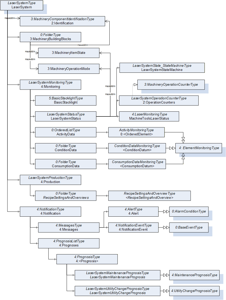
The structure of the model is inspired by the OPC 40501-1 Information Model for Machine Tools. An instance representation can be seen in Figure 6. Each instance of the LaserSystemType is representative of an individual laser system. All information regarding this one laser system is topically structured in five objects:
The first object is of the MachineryComponentIdentificationType and is used to identify the individual laser system.
The second object is the folder with all of the used MachineryBuildingBlocks which are used in the entire model. Its presence is required by the OPC 40001-1, in order to easily identify these blocks in different servers.
The third object is of the LaserSystemMonitoringType (see chapter 7.2), it structures all status and monitoring information of an individual laser system.
The fourth object is of the LaserSystemProductionType (see chapter 7.4) it aggregates production related information.
The fifth object is used to structure information regarding errors, warnings and notifications, it is also used to indicate to be executed maintenance activities (see chapter 7.3).
7 OPC UA ObjectTypes
7.1 LaserSystem ObjectType Definition
The LaserSystemType defines the top level OPC UA Object for a laser system. Each instance is representative of one laser system and thus aggregates all information relevant to the individual system. It is modelled similarly to the MachineToolType in OPC 40501-1.
The LaserSystemType is formally defined in Table 15.
| Attribute | Value | ||||
| BrowseName | LaserSystemType | ||||
| IsAbstract | False | ||||
| References | Node Class | BrowseName | DataType | TypeDefinition | Other |
|---|---|---|---|---|---|
| Subtype of the 0:BaseObjectType defined in OPC 10000-5 i.e. inheriting the InstanceDeclarations of that Node. | |||||
| 0:HasAddIn | Object | 2:Identification | 3:MachineryComponentIdentificationType | M | |
| 0:HasComponent | Object | 3:MachineryBuildingBlocks | 0:FolderType | M | |
| 0:HasComponent | Object | 4:Monitoring | LaserSystemMonitoringType | M | |
| 0:HasComponent | Object | 4:Notification | 4:NotificationType | M | |
| 0:HasComponent | Object | 4:Production | LaserSystemProductionType | M | |
| Conformance Units | |||||
|---|---|---|---|---|---|
| LaserSystems LaserSystemType Basic |
2:Identification (see Table 16), Monitoring (see chapter 7.2), 4:Notification (see chapter 7.3) and Production (see chapter 7.4) are instances of the respective types. They are used to structure the information in the LaserSystemType topically.
The components of the LaserSystemType have additional references which are defined in Table 16.
| SourceBrowsePath | Reference Type | Is Forward | TargetBrowsePath |
| 3:MachineryBuildingBlocks | 0:HasAddIn | True |
| |||
| 3:MachineryBuildingBlocks | 0:HasAddIn | True |
| |||
| 3:MachineryBuildingBlocks | 0:HasAddIn | True |
| |||
| 3:MachineryBuildingBlocks | 0:HasAddIn | True | 2:Identification |
7.2 Monitoring
7.2.1 LaserSystemMonitoring ObjectType Definition
The LaserSystemMonitoringType is used to aggregate all monitoring data related to a laser system. It is modelled similarly to the MonitoringType in OPC 40501-1: Machine Tools.
The LaserSystemMonitoringType is formally defined in Table 17.
| Attribute | Value | ||||
| BrowseName | LaserSystemMonitoringType | ||||
| IsAbstract | False | ||||
| References | Node Class | BrowseName | DataType | TypeDefinition | Other |
|---|---|---|---|---|---|
| Subtype of the 0:BaseObjectType defined in OPC 10000-5 i.e. inheriting the InstanceDeclarations of that Node. | |||||
| 0:HasComponent | Object | Stacklight | 5:BasicStacklightType | O | |
| 0:HasComponent | Object | LaserSystemStatus | LaserSystemStatusType | M | |
| 0:HasComponent | Object | ActivityData | 0:OrderedListType | O | |
| 0:HasComponent | Object | ConditionData | 0:FolderType | O | |
| 0:HasComponent | Object | ConsumptionData | 0:FolderType | O | |
| Conformance Units | |||||
|---|---|---|---|---|---|
| LaserSystems LaserSystemMonitoringType Basic |
Stacklight contains the information about a stacklight's composition and status. It is an object of 5:BasicStacklightType, defined in OPC 10000-200 Industrial Automation. If the machine tool has a stacklight available, the Stacklight shall be present.
LaserSystemStatus (see chapter 7.2.2), ActivityData (see chapter 7.2.5), ConditionData (see chapter 7.2.6) and ConsumptionData (see chapter 7.2.7) are instances of the respective types. They are used to structure the information in the LaserSystemMonitoringType topically.
The components of the LaserSystemMonitoringType have additional subcomponents which are defined in Table 18.
| Source Path | Reference | NodeClass | BrowseName | DataType | TypeDefinition | Others |
| ActivityData | 0:HasOrderedComponent | Object | <ActivityData> | ActivityDataMonitoringType | OP | |
| ConditionData | 0:HasComponent | Object | <ConditionData> | ConditionDataMonitoringType | OP | |
| ConsumptionData | 0:HasComponent | Object | <ConsumptionData> | ConsumptionDataMonitoringType | OP |
7.2.2 LaserSystemStatus ObjectType Definition
The primary purpose of the LaserSystemState is to provide an interface from which one can quickly determine what state the laser system is in, to make statements about the availability of the system. This is done via a laser system specific state machine of the LaserSystemState_StateMachineType and an OperationCounters. To increase the interoperability of this LaserSystemState interface, to for example existing MES, existing status and operation mode state machines as well as monitoring types as defined in OPC 40001-1: Machinery Basic Building Blocks and OPC 40501-1: Machine Tools are also included.
The LaserSystemStatusType is formally defined in in Table 19.
| Attribute | Value | ||||
| BrowseName | LaserSystemStatusType | ||||
| IsAbstract | False | ||||
| References | Node Class | BrowseName | DataType | TypeDefinition | Other |
|---|---|---|---|---|---|
| Subtype of the 0:BaseObjectType defined in OPC 10000-5 i.e. inheriting the InstanceDeclarations of that Node. | |||||
| 0:HasComponent | Object | LaserSystemState | LaserSystemState_StateMachineType | M | |
| 0:HasComponent | Object | MachineToolsLaserStatus | 4:LaserMonitoringType | M | |
| 0:HasAddIn | Object | 3:MachineryItemState | 3:MachineryItemState_StateMachineType | M | |
| 0:HasAddIn | Object | 3:MachineryOperationMode | 3:MachineryOperationModeStateMachineType | M | |
| 0:HasAddIn | Object | 2:OperationCounters | LaserSystemOperationCounterType | M | |
| Conformance Units | |||||
|---|---|---|---|---|---|
| LaserSystems LaserSystemStatusType Basic | |||||
LaserSystemState (see chapter 7.2.4), MachineToolsLaserStatus, 3:MachineryItemState, 3:MachineryOperationMode and 2:OperationCounters (see chapter 7.2.3) are instances of the respective types.
The states for the 3:MachineryItemState and the 3:MachineryOperationMode as well as the variable values for the MachineToolsLaserStatus are to be derived via Table 20. The mapping is only to be used unidirectionally from the LaserSystemState state to the other states or variables.
| LaserSystemState_StateMachine | MachineToolsLaserStatus : LaserState | MachineToolsLaserStatus : ControllerIsOn | MachineryItemStateMachine | MachineryOperationModeStateMachine |
| Off | Undefined | False | NotAvailable | None |
| EnergySaving | Undefined | True | NotAvailable | Setup |
| Idle | Undefined | True | NotExecuting | Setup |
| SetUp | Undefined | True | NotExecuting | Setup |
| LaserReady | Ready | True | Executing | Processing |
| Maintenance | Undefined | True | Executing | Maintenance |
| Error | Error | True | OutOfServiceSate | None |
| LaserOn | Active | True | Executing | Processing |
7.2.3 LaserSystemOperationCounter ObjectType Definition
The LaserSystemOperationCounterType gives an overview of how long the system has been in use.
The LaserSystemOperationCounterType is formally defined in Table 21.
| Attribute | Value | ||||
| BrowseName | LaserSystemOperationCounterType | ||||
| IsAbstract | False | ||||
| References | Node Class | BrowseName | DataType | TypeDefinition | Other |
|---|---|---|---|---|---|
| Subtype of the 3:MachineryOperationCounterType defined in OPC 40001-1 i.e. inheriting the InstanceDeclarations of that Node. | |||||
| 0:HasProperty | Variable | 2:PowerOnDuration | 0:Duration | 0:PropertyType | M, RO |
| 0:HasProperty | Variable | 2:OperationDuration | 0:Duration | 0:PropertyType | M, RO |
| 0:HasProperty | Variable | 0:DefaultInstanceBrowseName | 0:QualifiedName | 0:PropertyType | |
| 0:HasInterface | ObjectType | 2:IOperationCounterType | |||
| Conformance Units | |||||
|---|---|---|---|---|---|
| LaserSystems LaserSystemOperationCounterType Basic | |||||
| 3:Machinery Operation Counter |
The mandatory 2:PowerOnDuration is the duration the laser system has been powered on. It shall be used as defined by OPC 10000-100.
The mandatory 2:OperationDuration is the duration in which the laser system has actively emitted radiation, This, for example, is not the case if radiation is only caused by a trickle current.
Note: Incrementing the above two variables in a minute interval is deemed sufficient.
Note: The definition for the above two variable is intentionally vague and may differ from manufacturer to manufacturer.
7.2.4 LaserSystemState_StateMachine ObjectType Definition
Instances of the LaserSystemState_StateMachine are used to quickly indicate the current state of a laser system. This is done using a FiniteStateMachine as defined in OPC 10000-16. The chosen states (see Figure 7) are generalized and not manufacturer specific, to allow a wide variety of laser systems to be represented by this state machine. Furthermore, manufacturers can extend this state machine by further substates. Since the intention of this specification is not to restrict the transitions between the states, the state machine defines transitions between all states. Instances might restrict the usage of the defined states and transitions. An overview of the state machine is given in Figure 7, this is complimented by model overview in Figure 8 and the LaserSystemState_StateMachine is formally defined in Table 22.
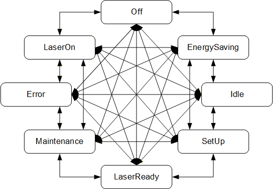
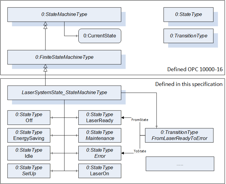
Figure 8 depicts how the LaserSystemState_StateMachineType is derived from the FiniteStateMachineType as defined in OPC 10000-16.
| Attribute | Value | ||||
| BrowseName | LaserSystemState_StateMachineType | ||||
| IsAbstract | False | ||||
| References | Node Class | BrowseName | DataType | TypeDefinition | Other |
|---|---|---|---|---|---|
| Subtype of the 0:FiniteStateMachineType defined in OPC 10000-16, i.e. inheriting the InstanceDeclarations of that Node. | |||||
| 0:HasProperty | Variable | 0:DefaultInstanceBrowseName | 0:QualifiedName | 0:PropertyType | |
| 0:HasComponent | Object | Off | 0:StateType | ||
| 0:HasComponent | Object | EnergySaving | 0:StateType | ||
| 0:HasComponent | Object | Idle | 0:StateType | ||
| 0:HasComponent | Object | SetUp | 0:StateType | ||
| 0:HasComponent | Object | LaserReady | 0:StateType | ||
| 0:HasComponent | Object | Maintenance | 0:StateType | ||
| 0:HasComponent | Object | Error | 0:StateType | ||
| 0:HasComponent | Object | LaserOn | 0:StateType | ||
| 0:HasComponent | Object | FromOffToOff | 0:TransitionType | ||
| 0:HasComponent | Object | FromOffToEnergySaving | 0:TransitionType | ||
| 0:HasComponent | Object | FromOffToIdle | 0:TransitionType | ||
| 0:HasComponent | Object | FromOffToSetUp | 0:TransitionType | ||
| 0:HasComponent | Object | FromOffToLaserReady | 0:TransitionType | ||
| 0:HasComponent | Object | FromOffToMaintenance | 0:TransitionType | ||
| 0:HasComponent | Object | FromOffToError | 0:TransitionType | ||
| 0:HasComponent | Object | FromOffToLaserOn | 0:TransitionType | ||
| 0:HasComponent | Object | FromEnergySavingToOff | 0:TransitionType | ||
| 0:HasComponent | Object | FromEnergySavingToEnergySaving | 0:TransitionType | ||
| 0:HasComponent | Object | FromEnergySavingToIdle | 0:TransitionType | ||
| 0:HasComponent | Object | FromEnergySavingToSetUp | 0:TransitionType | ||
| 0:HasComponent | Object | FromEnergySavingToLaserReady | 0:TransitionType | ||
| 0:HasComponent | Object | FromEnergySavingToMaintenance | 0:TransitionType | ||
| 0:HasComponent | Object | FromEnergySavingToError | 0:TransitionType | ||
| 0:HasComponent | Object | FromEnergySavingToLaserOn | 0:TransitionType | ||
| 0:HasComponent | Object | FromIdleToOff | 0:TransitionType | ||
| 0:HasComponent | Object | FromIdleToEnergySaving | 0:TransitionType | ||
| 0:HasComponent | Object | FromIdleToIdle | 0:TransitionType | ||
| 0:HasComponent | Object | FromIdleToSetUp | 0:TransitionType | ||
| 0:HasComponent | Object | FromIdleToLaserReady | 0:TransitionType | ||
| 0:HasComponent | Object | FromIdleToMaintenance | 0:TransitionType | ||
| 0:HasComponent | Object | FromIdleToError | 0:TransitionType | ||
| 0:HasComponent | Object | FromIdleToLaserOn | 0:TransitionType | ||
| 0:HasComponent | Object | FromSetUpToOff | 0:TransitionType | ||
| 0:HasComponent | Object | FromSetUpToEnergySaving | 0:TransitionType | ||
| 0:HasComponent | Object | FromSetUpToIdle | 0:TransitionType | ||
| 0:HasComponent | Object | FromSetUpToSetUp | 0:TransitionType | ||
| 0:HasComponent | Object | FromSetUpToLaserReady | 0:TransitionType | ||
| 0:HasComponent | Object | FromSetUpToMaintenance | 0:TransitionType | ||
| 0:HasComponent | Object | FromSetUpToError | 0:TransitionType | ||
| 0:HasComponent | Object | FromSetUpToLaserOn | 0:TransitionType | ||
| 0:HasComponent | Object | FromLaserReadyToOff | 0:TransitionType | ||
| 0:HasComponent | Object | FromLaserReadyToEnergySaving | 0:TransitionType | ||
| 0:HasComponent | Object | FromLaserReadyToIdle | 0:TransitionType | ||
| 0:HasComponent | Object | FromLaserReadyToSetUp | 0:TransitionType | ||
| 0:HasComponent | Object | FromLaserReadyToLaserReady | 0:TransitionType | ||
| 0:HasComponent | Object | FromLaserReadyToMaintenance | 0:TransitionType | ||
| 0:HasComponent | Object | FromLaserReadyToError | 0:TransitionType | ||
| 0:HasComponent | Object | FromLaserReadyToLaserOn | 0:TransitionType | ||
| 0:HasComponent | Object | FromMaintenanceToOff | 0:TransitionType | ||
| 0:HasComponent | Object | FromMaintenanceToEnergySaving | 0:TransitionType | ||
| 0:HasComponent | Object | FromMaintenanceToIdle | 0:TransitionType | ||
| 0:HasComponent | Object | FromMaintenanceToSetUp | 0:TransitionType | ||
| 0:HasComponent | Object | FromMaintenanceToLaserReady | 0:TransitionType | ||
| 0:HasComponent | Object | FromMaintenanceToMaintenance | 0:TransitionType | ||
| 0:HasComponent | Object | FromMaintenanceToError | 0:TransitionType | ||
| 0:HasComponent | Object | FromMaintenanceToLaserOn | 0:TransitionType | ||
| 0:HasComponent | Object | FromErrorToOff | 0:TransitionType | ||
| 0:HasComponent | Object | FromErrorToEnergySaving | 0:TransitionType | ||
| 0:HasComponent | Object | FromErrorToIdle | 0:TransitionType | ||
| 0:HasComponent | Object | FromErrorToSetUp | 0:TransitionType | ||
| 0:HasComponent | Object | FromErrorToLaserReady | 0:TransitionType | ||
| 0:HasComponent | Object | FromErrorToMaintenance | 0:TransitionType | ||
| 0:HasComponent | Object | FromErrorToError | 0:TransitionType | ||
| 0:HasComponent | Object | FromErrorToLaserOn | 0:TransitionType | ||
| 0:HasComponent | Object | FromLaserOnToOff | 0:TransitionType | ||
| 0:HasComponent | Object | FromLaserOnToEnergySaving | 0:TransitionType | ||
| 0:HasComponent | Object | FromLaserOnToIdle | 0:TransitionType | ||
| 0:HasComponent | Object | FromLaserOnToSetUp | 0:TransitionType | ||
| 0:HasComponent | Object | FromLaserOnToLaserReady | 0:TransitionType | ||
| 0:HasComponent | Object | FromLaserOnToMaintenance | 0:TransitionType | ||
| 0:HasComponent | Object | FromLaserOnToError | 0:TransitionType | ||
| 0:HasComponent | Object | FromLaserOnToLaserOn | 0:TransitionType | ||
| Conformance Units |
| LaserSystems LaserSystemState_StateMachineType Basic |
The States and Transitions define a StateMachine as shown in Figure 7. It does not define an initial State, i.e., the initial State is vendor-specific.
Note: None of the States or Transitions have a ModellingRule, i.e., they are only provided in the TypeDefinition, not on the instance. The CurrentState Variable (inherited from StateMachineType) contains the information of the current State of the instance.
Off is the state used to represent when a laser system is either completely shut down or in a system state below EnergySaving and thus very close to completely shut down (e.g., deep hibernation).
Note: In the Off state the OPC UA server of the laser system might actually not be reachable by an OPC UA client. However, by setting the Off state as part of the shutdown procedure an already connected client would know the last state was the Off state indicating that a normal shut down procedure was executed.
EnergySaving indicates that the energy consumption of the laser system is deliberately reduced. This can indicate a wide array of system states, reaching from close to the Off state (e.g., hibernation) to merely one or two elements of a laser system (e.g., a coolant pump) having reduced their power consumption.
Idle indicates that the laser system is not in an EnergySaving state, passively running while no preparing to achieve the LaserOn state and is thus also not in the SetUp state.
SetUp indicates that the system is currently actively doing something (e.g., bringing components to operating temperature) in order to achieve the LaserReady state.
LaserReady indicates that the laser system is merely missing a trigger before actively emitting radiation.
Maintenance indicates all states where the system is currently not able to operate due to for example software updates or hardware checkups.
Error indicates all states in which the system can currently not operate as an error is present. A closer description of the error can be taken form object instances described in chapter 7.3.
LaserOn is the only state in which the laser system is actively emitting radiation.
The components of the LaserSystemState_StateMachineType have additional references which are defined in Table 23.
| SourceBrowsePath | Reference Type | Is Forward | TargetBrowsePath |
| FromOffToOff | 0:FromState | True | Off |
| 0:ToState | True | Off | |
| FromOffToEnergySaving | 0:FromState | True | Off |
| 0:ToState | True | EnergySaving | |
| FromOffToIdle | 0:FromState | True | Off |
| 0:ToState | True | Idle | |
| FromOffToSetUp | 0:FromState | True | Off |
| 0:ToState | True | SetUp | |
| FromOffToLaserReady | 0:FromState | True | Off |
| 0:ToState | True | LaserReady | |
| FromOffToMaintenance | 0:FromState | True | Off |
| 0:ToState | True | Maintenance | |
| FromOffToError | 0:FromState | True | Off |
| 0:ToState | True | Error | |
| FromOffToLaserOn | 0:FromState | True | Off |
| 0:ToState | True | LaserOn | |
| FromEnergySavingToOff | 0:FromState | True | EnergySaving |
| 0:ToState | True | Off | |
| FromEnergySavingToEnergySaving | 0:FromState | True | EnergySaving |
| 0:ToState | True | EnergySaving | |
| FromEnergySavingToIdle | 0:FromState | True | EnergySaving |
| 0:ToState | True | Idle | |
| FromEnergySavingToSetUp | 0:FromState | True | EnergySaving |
| 0:ToState | True | SetUp | |
| FromEnergySavingToLaserReady | 0:FromState | True | EnergySaving |
| 0:ToState | True | LaserReady | |
| FromEnergySavingToMaintenance | 0:FromState | True | EnergySaving |
| 0:ToState | True | Maintenance | |
| FromEnergySavingToError | 0:FromState | True | EnergySaving |
| 0:ToState | True | Error | |
| FromEnergySavingToLaserOn | 0:FromState | True | EnergySaving |
| 0:ToState | True | LaserOn | |
| FromIdleToOff | 0:FromState | True | Idle |
| 0:ToState | True | Off | |
| FromIdleToEnergySaving | 0:FromState | True | Idle |
| 0:ToState | True | EnergySaving | |
| FromIdleToIdle | 0:FromState | True | Idle |
| 0:ToState | True | Idle | |
| FromIdleToSetUp | 0:FromState | True | Idle |
| 0:ToState | True | SetUp | |
| FromIdleToLaserReady | 0:FromState | True | Idle |
| 0:ToState | True | LaserReady | |
| FromIdleToMaintenance | 0:FromState | True | Idle |
| 0:ToState | True | Maintenance | |
| FromIdleToError | 0:FromState | True | Idle |
| 0:ToState | True | Error | |
| FromIdleToLaserOn | 0:FromState | True | Idle |
| 0:ToState | True | LaserOn | |
| FromSetUpToOff | 0:FromState | True | SetUp |
| 0:ToState | True | Off | |
| FromSetUpToEnergySaving | 0:FromState | True | SetUp |
| 0:ToState | True | EnergySaving | |
| FromSetUpToIdle | 0:FromState | True | SetUp |
| 0:ToState | True | Idle | |
| FromSetUpToSetUp | 0:FromState | True | SetUp |
| 0:ToState | True | SetUp | |
| FromSetUpToLaserReady | 0:FromState | True | SetUp |
| 0:ToState | True | LaserReady | |
| FromSetUpToMaintenance | 0:FromState | True | SetUp |
| 0:ToState | True | Maintenance | |
| FromSetUpToError | 0:FromState | True | SetUp |
| 0:ToState | True | Error | |
| FromSetUpToLaserOn | 0:FromState | True | SetUp |
| 0:ToState | True | LaserOn | |
| FromLaserReadyToOff | 0:FromState | True | LaserReady |
| 0:ToState | True | Off | |
| FromLaserReadyToEnergySaving | 0:FromState | True | LaserReady |
| 0:ToState | True | EnergySaving | |
| FromLaserReadyToIdle | 0:FromState | True | LaserReady |
| 0:ToState | True | Idle | |
| FromLaserReadyToSetUp | 0:FromState | True | LaserReady |
| 0:ToState | True | SetUp | |
| FromLaserReadyToLaserReady | 0:FromState | True | LaserReady |
| 0:ToState | True | LaserReady | |
| FromLaserReadyToMaintenance | 0:FromState | True | LaserReady |
| 0:ToState | True | Maintenance | |
| FromLaserReadyToError | 0:FromState | True | LaserReady |
| 0:ToState | True | Error | |
| FromLaserReadyToLaserOn | 0:FromState | True | LaserReady |
| 0:ToState | True | LaserOn | |
| FromMaintenanceToOff | 0:FromState | True | Maintenance |
| 0:ToState | True | Off | |
| FromMaintenanceToEnergySaving | 0:FromState | True | Maintenance |
| 0:ToState | True | EnergySaving | |
| FromMaintenanceToIdle | 0:FromState | True | Maintenance |
| 0:ToState | True | Idle | |
| FromMaintenanceToSetUp | 0:FromState | True | Maintenance |
| 0:ToState | True | SetUp | |
| FromMaintenanceToLaserReady | 0:FromState | True | Maintenance |
| 0:ToState | True | LaserReady | |
| FromMaintenanceToMaintenance | 0:FromState | True | Maintenance |
| 0:ToState | True | Maintenance | |
| FromMaintenanceToError | 0:FromState | True | Maintenance |
| 0:ToState | True | Error | |
| FromMaintenanceToLaserOn | 0:FromState | True | Maintenance |
| 0:ToState | True | LaserOn | |
| FromErrorToOff | 0:FromState | True | Error |
| 0:ToState | True | Off | |
| FromErrorToEnergySaving | 0:FromState | True | Error |
| 0:ToState | True | EnergySaving | |
| FromErrorToIdle | 0:FromState | True | Error |
| 0:ToState | True | Idle | |
| FromErrorToSetUp | 0:FromState | True | Error |
| 0:ToState | True | SetUp | |
| FromErrorToLaserReady | 0:FromState | True | Error |
| 0:ToState | True | LaserReady | |
| FromErrorToMaintenance | 0:FromState | True | Error |
| 0:ToState | True | Maintenance | |
| FromErrorToError | 0:FromState | True | Error |
| 0:ToState | True | Error | |
| FromErrorToLaserOn | 0:FromState | True | Error |
| 0:ToState | True | LaserOn | |
| FromLaserOnToOff | 0:FromState | True | LaserOn |
| 0:ToState | True | Off | |
| FromLaserOnToEnergySaving | 0:FromState | True | LaserOn |
| 0:ToState | True | EnergySaving | |
| FromLaserOnToIdle | 0:FromState | True | LaserOn |
| 0:ToState | True | Idle | |
| FromLaserOnToSetUp | 0:FromState | True | LaserOn |
| 0:ToState | True | SetUp | |
| FromLaserOnToLaserReady | 0:FromState | True | LaserOn |
| 0:ToState | True | LaserReady | |
| FromLaserOnToMaintenance | 0:FromState | True | LaserOn |
| 0:ToState | True | Maintenance | |
| FromLaserOnToError | 0:FromState | True | LaserOn |
| 0:ToState | True | Error | |
| FromLaserOnToLaserOn | 0:FromState | True | LaserOn |
| 0:ToState | True | LaserOn |
The component Variables of the LaserSystemState_StateMachineType have additional Attributes defined in Table 24
| Source Path | Value Attribute | Description Attribute | ||
| 0:DefaultInstanceBrowseName | LaserSystemState | The default BrowseName for instances of the type | ||
| Off | The laser system is currently off or very close to off | |||
| EnergySaving | The laser system is actively reducing its energy consumption | |||
| Idle | The laser system is operational but not perusing any activities to achieve the LaserReady state | |||
| SetUp | The laser system is performing activities to achieve the LaserReady state | |||
| LaserReady | The laser system is ready and is merely missing a trigger to actively emit radiation | |||
| Maintenance | The laser system is currently not operational as maintenance is being performed on it | |||
| Error | The laser system is not operational as it is in an error state | |||
| LaserOn | The laser system is actively emitting radiation | |||
| 0 | |||
| 1 | |||
| 2 | |||
| 3 | |||
| 4 | |||
| 5 | |||
| 6 | |||
| 7 | |||
| 0 | |||
| 1 | |||
| 2 | |||
| 3 | |||
| 4 | |||
| 5 | |||
| 6 | |||
| 7 | |||
| 8 | |||
| 9 | |||
| 10 | |||
| 11 | |||
| 12 | |||
| 13 | |||
| 14 | |||
| 15 | |||
| 16 | |||
| 17 | |||
| 18 | |||
| 19 | |||
| 20 | |||
| 21 | |||
| 22 | |||
| 23 | |||
| 24 | |||
| 25 | |||
| 26 | |||
| 27 | |||
| 28 | |||
| 29 | |||
| 30 | |||
| 31 | |||
| 32 | |||
| 33 | |||
| 34 | |||
| 35 | |||
| 36 | |||
| 37 | |||
| 38 | |||
| 39 | |||
| 40 | |||
| 41 | |||
| 42 | |||
| 43 | |||
| 44 | |||
| 45 | |||
| 46 | |||
| 47 | |||
| 48 | |||
| 49 | |||
| 50 | |||
| 51 | |||
| 52 | |||
| 53 | |||
| 54 | |||
| 55 | |||
| 56 | |||
| 57 | |||
| 58 | |||
| 59 | |||
| 60 | |||
| 61 | |||
| 62 | |||
| 63 |
7.2.5 ActivityDataMonitoring ObjectType Definition
The ActivityDataMonitoringType provides information about high-level logging of the activities performed on a laser system. This enables for example the tracking of configuration changes.
The ActivityDataMonitoringType is formally defined in Table 25.
| Attribute | Value | ||||
| BrowseName | ActivityDataMonitoringType | ||||
| IsAbstract | False | ||||
| References | Node Class | BrowseName | DataType | TypeDefinition | Other |
|---|---|---|---|---|---|
| Subtype of the 4:ElementMonitoringType defined in OPC 40501-1 i.e. inheriting the InstanceDeclarations of that Node. | |||||
| 0:HasProperty | Variable | ParameterIdentifier | 0:String | 0:PropertyType | M, RO |
| 0:HasComponent | Variable | PreviousValue | 0:Number | 0:AnalogUnitType | O, RO |
| 0:HasComponent | Variable | CurrentValue | 0:Number | 0:AnalogUnitType | M, RO |
| 0:HasComponent | Variable | Description | 0:LocalizedText | 0:BaseDataVariableType | O, RO |
| 0:HasInterface | ObjectType | 0:IOrderedObjectType | |||
| Applied from 0:IOrderedObjectType | |||||
| 0:HasProperty | Variable | 0:NumberInList | 0:UInt16 | 0:PropertyType | M, RO |
| Conformance Units | |||||
|---|---|---|---|---|---|
| LaserSystems ActivityDataMonitoringType Basic |
The 4:Name is a human-readable string containing the name of the configuration parameter, that is being changed. The uniqueness of this name cannot be assumed. The value of this Property may change during its life cycle.
ParameterIdentifier is a unique string identifier for a configuration parameter. The mandatory identifier is to be used to provide a unique ID. The value of this Property does not change during its life cycle.
The PreviousValue Component represents the value of the configuration parameter before a change, it is optional and given as number.
The CurrentValue Component represents the now current value of the of the configuration parameter in question, it is mandatory and given as number.
The optional Description Component represents a human-readable description of the configuration change.
Note: The change time stamp is given by the source time stamp of the node.
7.2.6 ConditionDataMonitoring ObjectType Definition
The ConditionDataMonitoringType provides specific information about current condition data of the laser system. Warning and error levels identify the specified working range of the monitored condition parameter.
The ConditionDataMonitoringType is formally defined in Table 26.
| Attribute | Value | ||||
| BrowseName | ConditionDataMonitoringType | ||||
| IsAbstract | False | ||||
| References | Node Class | BrowseName | DataType | TypeDefinition | Other |
|---|---|---|---|---|---|
| Subtype of the 4:ElementMonitoringType defined in OPC 40501-1 i.e. inheriting the InstanceDeclarations of that Node.… | |||||
| 0:HasProperty | Variable | ConditionParameterIdentifier | 0:String | 0:PropertyType | M, RO |
| 0:HasComponent | Variable | Value | 0:Number | 0:AnalogUnitType | M, RO |
| 0:HasComponent | Variable | UpperWarningLevel | 0:Number | 0:AnalogUnitType | O, RO |
| 0:HasComponent | Variable | UpperErrorLevel | 0:Number | 0:AnalogUnitType | O, RO |
| 0:HasComponent | Variable | LowerWarningLevel | 0:Number | 0:AnalogUnitType | O, RO |
| 0:HasComponent | Variable | LowerErrorLevel | 0:Number | 0:AnalogUnitType | O, RO |
| 0:HasComponent | Variable | Description | 0:LocalizedText | 0:BaseDataVariableType | O, RO |
| Conformance Units | |||||
|---|---|---|---|---|---|
| LaserSystems ConditionDataMonitoringType Basic |
The 4:Name Property represents a human-readable name of the monitored condition parameter. The uniqueness of this name cannot be assumed. The value of this Property may change during its life cycle. Examples are: "current temperature", "power consumption".
The mandatory ConditionParameterIdentifier is a unique string for identifying the monitored condition parameter. The Property is to be used to provide a unique ID, the value of which does not change during its life cycle.
The Value Component represents the current value of the monitored condition parameter. The Value is mandatory and given as number. The value should be updated frequently to match the current circumstances. Examples are: "2000", "0.4563", "-11"
UpperWarningLevel is a mandatory and given as number. This Component represents the upper limit for the monitored condition parameter above which a warning message is expected.
The mandatory UpperErrorLevel Component represents the maximum value permitted or the monitored condition parameter. If exceeded an error message is expected.
LowerWarningLevel is a mandatory and given as number. This Component represents the lower limit for the monitored condition parameter below which a warning message is expected.
The mandatory LowerErrorLevel Component represents the minimum value permitted for the monitored condition parameter. If exceeded an error message is expected.
The optional Description Component represents a human-readable description of the monitored condition parameter.
7.2.7 ConsumptionDataMonitoring ObjectType Definition
The ConsumptionDataMonitoringType provides information about the external media consumption (e.g., power consumption, compressed air, cooling water). This enables the identification of the consumables the laser system is equipped with.
The ConsumptionDataMonitoringType is formally defined in Table 27.
| Attribute | Value | ||||
| BrowseName | ConsumptionDataMonitoringType | ||||
| IsAbstract | False | ||||
| References | Node Class | BrowseName | DataType | TypeDefinition | Other |
|---|---|---|---|---|---|
| Subtype of the 4:ElementMonitoringType defined in OPC 40501-1 i.e. inheriting the InstanceDeclarations of that Node. | |||||
| 0:HasProperty | Variable | ConsumableIdentifier | 0:String | 0:PropertyType | M, RO |
| 0:HasComponent | Variable | Value | 0:Number | 0:AnalogUnitType | M, RO |
| 0:HasComponent | Variable | Description | 0:LocalizedText | 0:BaseDataVariableType | O, RO |
| Conformance Units |
| LaserSystems ConsumptionDataMonitoringType Basic |
The 4:Name is a human-readable string containing the name of the monitored media consumption parameter. The uniqueness of this name cannot be assumed based on this information. The value of this Property might change during its life cycle. Examples are: "power consumption", "compressed air", "cooling water".
ConsumableIdentifier is a unique string identifier for a media consumption parameter. The mandatory Identifier is to be used to provide a unique ID. The value of this Property does not change during its life cycle.
The Value Component represents the current value of the monitored media consumption parameter. The Value is mandatory and given as number. The value should be updated frequently to match the represented current circumstances of the monitored media consumption parameter. Examples are: "2000", "0.4563", "-11"
The optional Description Component represents a human-readable description of the monitored media consumption parameter.
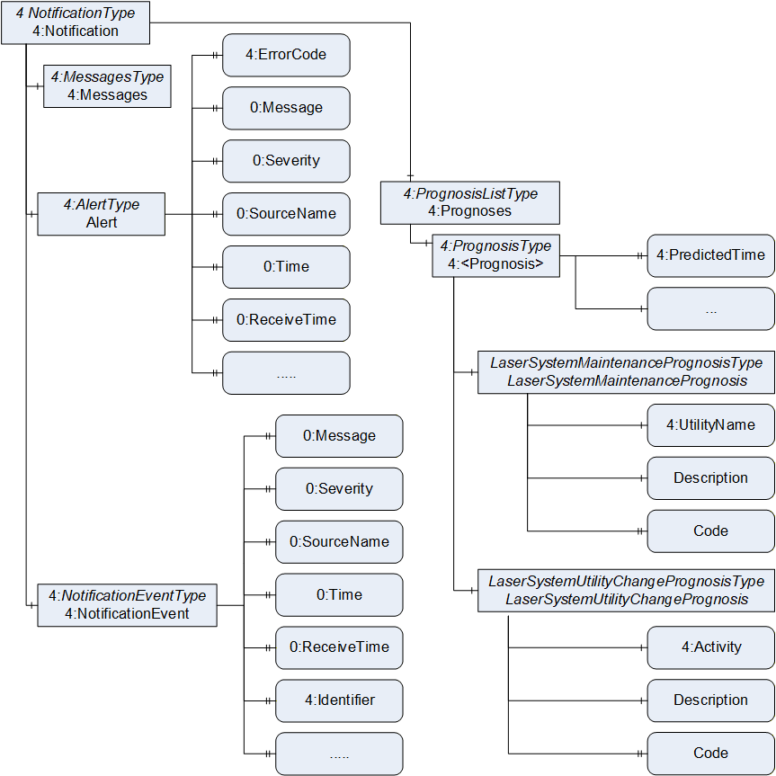
7.3 Notification
Notification is used to provide an interface for laser systems to deliver information about errors, warnings and notifications (see the use case in chapter 5.2), this specification reuses all concepts of the MessagesType as defined in OPC 40501-1: Machine Tools.
Furthermore, this specification reuses the 4:PrognosisType as defined in OPC 40501-1: Machine Tools to provide an interface for delivering information regarding upcoming maintenance activities.
Note: The goal of the interface is not, provide information to a higher-level system which tracks when which components were changed or when a service was executed.
To tailor the existing model to laser systems and the use case described in chapter 5.3, two subtypes, the LaserSystemMaintenancePrognosisType and the LaserSystemUtilityChangePrognosisType are derived in chapter 7.3.1 and 7.3.2.
Figure 9 gives an overview of NotificationType model as defined in OPC 40501-1 and how the LaserSystemMaintenancePrognosisType and LaserSystemUtilityChangePrognosisType definitions extend that model.
7.3.1 LaserSystemMaintenancePrognosis ObjectType Definition
The LaserSystemMaintenancePrognosisType provides an interface to quickly identify which kind of maintenance is to be performed on a laser system and when this maintenance is due
The LaserSystemMaintenancePrognosisType is formally defined in Table 28.
| Attribute | Value | ||||
| BrowseName | LaserSystemMaintenancePrognosisType | ||||
| IsAbstract | False | ||||
| References | Node Class | BrowseName | DataType | TypeDefinition | Other |
|---|---|---|---|---|---|
| Subtype of the 4:MaintenancePrognosisType defined in OPC 40501-1 i.e. inheriting the InstanceDeclarations of that Node. | |||||
| 0:HasComponent | Variable | Description | 0:LocalizedText | 0:BaseDataVariableType | M, RO |
| 0:HasProperty | Variable | Code | 0:String | 0:PropertyType | O, RO |
| Conformance Units | |||||
|---|---|---|---|---|---|
| LaserSystems LaserSystemMaintenancePrognosisType Basic |
The 4:PredictedTime as defined by the 4:PrognosisType is used to indicate the point in time the predicted user interaction will become necessary.
The 4:Activity as defined in the super type 4:MaintenancePrognosisType is to be used to indicate the name of the activity to be executed on the machine. Examples may be "General service A" or "Check up of the main coolant loop".
The Description indicates in a more elaborate (as compared to 4:UtilityName) and textual form what is to be done for the specific maintenance.
The Code may, for example, be used to link a maintenance activity to one specified in a service manual.
7.3.2 LaserSystemUtilityChangePrognosis ObjectType Definition
The LaserSystemUtilityChangePrognosisType is to be used as an interface indicating upcoming maintenance measures, in which utilities are to be exchanged. One such might be the change of a filter or the refilling of a water coolant system.
Note: The LaserSystemUtilityChangePrognosisType differs from the LaserSystemMaintenancePrognosisType as it always refers to one specific component which is to be serviced.
The LaserSystemUtilityChangePrognosisType is formally defined in Table 29.
| Attribute | Value | ||||
| BrowseName | LaserSystemUtilityChangePrognosisType | ||||
| IsAbstract | False | ||||
| References | Node Class | BrowseName | DataType | TypeDefinition | Other |
|---|---|---|---|---|---|
| Subtype of the 4:UtilityChangePrognosisType defined in OPC 40501-1 i.e. inheriting the InstanceDeclarations of that Node. | |||||
| 0:HasComponent | Variable | Description | 0:LocalizedText | 0:BaseDataVariableType | M, RO |
| 0:HasProperty | Variable | Code | 0:String | 0:PropertyType | O, RO |
| Conformance Units | |||||
|---|---|---|---|---|---|
| LaserSystems LaserSystemUtilityChangePrognosisType Basic |
The 4:PredictedTime as defined the 4:PrognosisType is used to indicate the point in time the utility change will become necessary.
The 4:UtilityName as defined in the super type 4:UtilityChangePrognosisType is to be used to indicate the name of the utility to be exchanged. Examples may be "Air filter" or "Coolant water".
The Description indicates in a more elaborate (as compared to 4:UtilityName) and textual form what is to be done for the specific utility change.
The Code may, for example, be used to link a maintenance activity to one specified in a service manual.
7.4 Production
7.4.1 LaserSystemProduction ObjectType Definition
The LaserSystemProductionType is modelled similarly to the 4:ProductionType as defined in OPC 40501-1. It is used to structure all production related data linked to a laser system.
The LaserSystemProductionType is formally defined in Table 30.
| Attribute | Value | ||||
| BrowseName | LaserSystemProductionType | ||||
| IsAbstract | False | ||||
| References | Node Class | BrowseName | DataType | TypeDefinition | Other |
|---|---|---|---|---|---|
| Subtype of the 0:BaseObjectType defined in OPC 10000-5 i.e. inheriting the InstanceDeclarations of that Node. | |||||
| 0:HasComponent | Object | RecipeSettingsAndOverviews | 0:FolderType | O | |
| Conformance Units | |||||
|---|---|---|---|---|---|
| LaserSystems LaserSystemProductionType Basic |
RecipeSettingsAndOverviews contains instances of the RecipeSettingsAndOverviewType (see chapter 7.4.2). It is used to structure production information.
The components of the LaserSystemProductionType have additional subcomponents which are defined in Table 31.
| Source Path | Reference | NodeClass | BrowseName | DataType | TypeDefinition | Others |
| RecipeSettingsAndOverviews | 0:HasComponent | Object | <Recipe> | RecipeSettingsAndOverviewType | OP |
7.4.2 RecipeSettingsAndOverview Type Definition
The RecipeSettingsAndOverviewType provides a list of all available recipes for a given laser system and offers further specifics of the recipe, like last usage, completed runs and revision status of the recipe. This enables an overview of all available recipe options for keeping the laser system updated and ready for use.
The RecipeSettingsAndOverviewType is formally defined in Table 32.
| Attribute | Value | ||||
| BrowseName | RecipeSettingsAndOverviewType | ||||
| IsAbstract | False | ||||
| References | Node Class | BrowseName | DataType | TypeDefinition | Other |
|---|---|---|---|---|---|
| Subtype of the 0:BaseObjectType defined in OPC 10000-5 i.e. inheriting the InstanceDeclarations of that Node. | |||||
| 0:HasProperty | Variable | RecipeName | 0:String | 0:PropertyType | O, RO |
| 0:HasProperty | Variable | RecipeIdentifier | 0:String | 0:PropertyType | M, RO |
| 0:HasProperty | Variable | LastUsage | 0:UtcTime | 0:PropertyType | M, RO |
| 0:HasComponent | Variable | RunsCompleted | 0:UInt64 | 0:BaseDataVariableType | M, RO |
| 0:HasProperty | Variable | RecipeRevision | 0:String | 0:PropertyType | O, RO |
| 0:HasProperty | Variable | LastModification | 0:UtcTime | 0:PropertyType | M, RO |
| 0:HasProperty | Variable | CreationDate | 0:UtcTime | 0:PropertyType | O, RO |
| 0:HasComponent | Variable | Description | 0:LocalizedText | 0:BaseDataVariableType | O, RO |
| Conformance Units | |||||
|---|---|---|---|---|---|
| LaserSystems RecipeSettingsAndOverviewType Basic |
The optional RecipeName is a human-readable string containing the name of the recipe. The uniqueness of this name cannot be assumed. The value of this Property might change during its life cycle.
RecipeIdentifier is a unique string identifier for a recipe. The mandatory Identifier is to be used to provide a unique ID. The value of this Property does not change during its life cycle.
LastUsage gives the time, when the specific recipe was last active. The Property is mandatory and uses the UtcTime DataType.
The mandatory Component RunsCompleted is a counter that is to be increased after each completed run of the recipe, it uses the DateType UInt32. This counter does not give any indication about the part quality.
The optional RecipeRevision Property is a human readable string, that indicates the current revision level of the recipe.
The LastModification Property gives the time, when the specific recipe was last modified. The Property is mandatory and uses the UtcTime DataType.
The optional CreationDate gives the time, when the specific recipe was first introduced. The Property uses the UtcTime DataType.
The optional Description Component represents a human-readable description of the recipe.
8 Profiles and ConformanceUnits
8.1 Conformance Units
This chapter defines the corresponding Conformance Units for the OPC UA Information Model for LaserSystems.
| Category | Title | Description |
| Server | LaserSystems LaserSystemType Basic | The LaserSystemType is represented in the AddressSpace All instances contain all nodes declared as mandatory in the LaserSystemType. Every optional node available in the instances matches the type definition. |
| Server | LaserSystems LaserSystemMonitoringType Basic | The LaserSystemMonitoringType is represented in the AddressSpace. All instances contain all nodes declared as mandatory in the LaserSystemMonitoringType. Every optional node available in the instances matches the type definition. |
| Server | LaserSystems LaserSystemStatusType Basic | The LaserSystemStatusType is represented in the AddressSpace. All instances contain all nodes declared as mandatory in the LaserSystemStatusType. Every optional node available in the instances matches the type definition. |
| Server | LaserSystems LaserSystemOperationCounterType Basic | The LaserSystemOperationCounterType is represented in the AddressSpace. All instances contain all nodes declared as mandatory in the LaserSystemOperationCounterType. Every optional node available in the instances matches the type definition. |
| Server | LaserSystems LaserSystemState_StateMachineType Basic | The LaserSystemState_StateMachineType is represented in the AddressSpace. All instances contain all nodes declared as mandatory in the LaserSystemState_StateMachineType. Every optional node available in the instances matches the type definition. |
| Server | LaserSystems ActivityDataMonitoringType Basic | The ActivityDataMonitoringType is represented in the AddressSpace. All instances contain all nodes declared as mandatory in the ActivityDataMonitoringType. Every optional node available in the instances matches the type definition. |
| Server | LaserSystems ConditionDataMonitoringType Basic | The ConditionDataMonitoringType is represented in the AddressSpace. All instances contain all nodes declared as mandatory in the ConditionDataMonitoringType. Every optional node available in the instances matches the type definition. |
| Server | LaserSystems ConsumptionDataMonitoringType Basic | The ConsumptionDataMonitoringType is represented in the AddressSpace. All instances contain all nodes declared as mandatory in the ConsumptionDataMonitoringType. Every optional node available in the instances matches the type definition. |
| Server | LaserSystems LaserSystemMaintenancePrognosisType Basic | The LaserSystemMaintenancePrognosisType is represented in the AddressSpace. All instances contain all nodes declared as mandatory in the LaserSystemMaintenancePrognosisType. Every optional node available in the instances matches the type definition. |
| Server | LaserSystems LaserSystemUtilityChangePrognosisType Basic | The LaserSystemUtilityChangePrognosisType is represented in the AddressSpace. All instances contain all nodes declared as mandatory in the LaserSystemUtilityChangePrognosisType. Every optional node available in the instances matches the type definition. |
| Server | LaserSystems LaserSystemProductionType Basic | The Laser LaserSystemProductionType is represented in the AddressSpace. All instances contain all nodes declared as mandatory in the LaserSystemProductionType. Every optional node available in the instances matches the type definition. |
| Server | LaserSystems RecipeSettingsAndOverviewType Basic | The RecipeSettingsAndOverviewType is represented in the AddressSpace. All instances contain all nodes declared as mandatory in the RecipeSettingsAndOverviewType. Every optional node available in the instances matches the type definition. |
8.2 Profiles
8.2.1 Profile list
Table 34 lists all Profiles defined in this document and defines their URIs.
| Profile | URI |
| LaserSystems Basic Server Profile | http://opcfoundation.org/UA-Profile/LaserSystems/Server/Basic |
| LaserSystems Stacklight Facet | http://opcfoundation.org/UA-Profile/LaserSystems/Server/Stacklight |
| LaserSystems Monitoring Facet | http://opcfoundation.org/UA-Profile/LaserSystems/Server/Monitoring |
| LaserSystems Notification Facet | http://opcfoundation.org/UA-Profile/LaserSystems/Server/Notification |
| LaserSystems Production Facet | http://opcfoundation.org/UA-Profile/LaserSystems/Server/Production |
8.2.2 Server Facets
8.2.2.1 Overview
The following sections specify the Facets available for Servers that implement the LaserSystems companion specification. Each section defines and describes a Facet or Profile.
8.2.2.2 LaserSystems Basic Server Profile
Table 35 defines a Profile that describes the minimum required content and address space functionality any LaserSystem server shall at least provide.
| Group | Conformance Unit / Profile Title | Mandatory / Optional |
| Profile | 0:Micro Embedded Device 2017 Server Profile | M |
| Base Information | 0:Base Info Placeholder Modelling Rules | M |
| Profile | 0:State Machine Server Facet | M |
| Base Information | 0:Base Info Custom Type System | M |
| Base Information | 0:Base Info Placeholder Modelling Rules | M |
| Profile | 3:Machinery Component Identification Server Facet | M |
| Profile | 3:Machinery State Server Facet | M |
| LaserSystems | LaserSystems LaserSystemState_StateMachineType Basic | M |
| LaserSystems | LaserSystems LaserSystemOperationCounterType Basic | M |
| Profile | 2:DI OperationCounter Interface | M |
8.2.2.3 LaserSystems Stacklight Facet
Table 36 defines a Facet which enables the provisioning stack light related information of a laser system.
| Group | Conformance Unit / Profile Title | Mandatory / Optional |
| Profie | LaserSystems Basic Server Profile | M |
| Profile | 5:IA Stacklight Server Profile | M |
8.2.2.4 LaserSystems Monitoring Facet
Table 37 defines a Facet that enables the provisioning of monitoring data for a laser system.
| Group | Conformance Unit / Profile Title | Mandatory / Optional |
| Profie | LaserSystems Basic Server Profile | M |
| Base Information | 0:Base Info Engineering Units | M |
| LaserSystems | LaserSystems ActivityDataMonitoringType Basic | M |
| LaserSystems | LaserSystems ConditionDataMonitoringType Basic | M |
| LaserSystems | LaserSystems ConsumptionDataMonitoringType Basic | M |
8.2.2.5 LaserSystems Notification Server Facet
Table 38 defines a Facet that enables the provisioning of errors, warnings, notifications and maintenance related information.
| Group | Conformance Unit / Profile Title | Mandatory / Optional |
| Profile | LaserSystems Basic Server Profile | M |
| Profile | 4:MachineTool Errors and Alerts Server Facet | M |
| LaserSystems | LaserSystems LaserSystemMaintenancePrognosisType Basic | M |
| LaserSystems | LaserSystems LaserSystemUtilityChangePrognosisType Basic | M |
8.2.2.6 LaserSystems Production Server Facet
Table 39 defines a Facet that enables the provisioning of recipe and setting information handled by the laser system.
| Group | Conformance Unit / Profile Title | Mandatory / Optional |
| Profile | LaserSystems Basic Server Profile | M |
| Profile | 4:MachineTool Prognoses Server Facet | M |
| LaserSystems | LaserSystems LaserSystemProductionType Basic | M |
| LaserSystems | LaserSystems RecipeSettingsAndOverviewType Basic | M |
9 Namespaces
9.1 Namespace Metadata
Table 40 defines the namespace metadata for this document. The Object is used to provide version information for the namespace and an indication about static Nodes. Static Nodes are identical for all Attributes in all Servers, including the Value Attribute. See OPC 10000-5 for more details.
The information is provided as Object of type NamespaceMetadataType. This Object is a component of the Namespaces Object that is part of the Server Object. The NamespaceMetadataType ObjectType and its Properties are defined in OPC 10000-5.
The version information is also provided as part of the ModelTableEntry in the UANodeSet XML file. The UANodeSet XML schema is defined in OPC 10000-6.
| Attribute | Value | ||
| BrowseName | http://opcfoundation.org/UA/LaserSystems/ | ||
| Property | DataType | Value | |
|---|---|---|---|
| NamespaceUri | String | http://opcfoundation.org/UA/LaserSystems/ | |
| NamespaceVersion | String | 1.0.0 | |
| NamespacePublicationDate | DateTime | 2024-02-01 | |
| IsNamespaceSubset | Boolean | False | |
| StaticNodeIdTypes | IdType [] | 0 | |
| StaticNumericNodeIdRange | NumericRange [] | - | |
| StaticStringNodeIdPattern | String | - | |
9.2 Handling of OPC UA Namespaces
Namespaces are used by OPC UA to create unique identifiers across different naming authorities. The Attributes NodeId and BrowseName are identifiers. A Node in the UA AddressSpace is unambiguously identified using a NodeId. Unlike NodeIds, the BrowseName cannot be used to unambiguously identify a Node. Different Nodes may have the same BrowseName. They are used to build a browse path between two Nodes or to define a standard Property.
Servers may often choose to use the same namespace for the NodeId and the BrowseName. However, if they want to provide a standard Property, its BrowseName shall have the namespace of the standards body although the namespace of the NodeId reflects something else, for example the EngineeringUnits Property. All NodeIds of Nodes not defined in this document shall not use the standard namespaces.
Table 41 provides a list of mandatory and optional namespaces used in an Laser Systems OPC UA Server.
| NamespaceURI | Description | Use |
| http://opcfoundation.org/UA/ | Namespace for NodeIds and BrowseNames defined in the OPC UA specification. This namespace shall have namespace index 0. | Mandatory |
| Local Server URI | Namespace for nodes defined in the local server. This namespace shall have namespace index 1. | Mandatory |
| http://opcfoundation.org/UA/DI/ | Namespace for NodeIds and BrowseNames defined in OPC 10000-100. The namespace index is Server specific. | Mandatory |
| http://opcfoundation.org/UA/Machinery/ | Namespace for NodeIds and BrowseNames defined in OPC 40001-1. The namespace index is Server specific. | Mandatory |
| http://opcfoundation.org/UA/IA/ | Namespace for NodeIds and BrowseNames defined in OPC 10000-200. The namespace index is Server specific. | Mandatory |
| http://opcfoundation.org/UA/MachineTool/ | Namespace for NodeIds and BrowseNames defined in OPC 40501-1. The namespace index is Server specific. | |
| http://opcfoundation.org/UA/LaserSystems/ | Namespace for NodeIds and BrowseNames defined in this document. The namespace index is Server specific. | Mandatory |
| Vendor specific types | A Server may provide vendor-specific types like types derived from ObjectTypes defined in this document in a vendor-specific namespace. | Optional |
| Vendor specific instances | A Server provides vendor-specific instances of the standard types or vendor-specific instances of vendor-specific types in a vendor-specific namespace. It is recommended to separate vendor specific types and vendor specific instances into two or more namespaces. | Mandatory |
Table 42 provides a list of namespaces and their indices used for BrowseNames in this document. The default namespace of this document is not listed since all BrowseNames without prefix use this default namespace.
| NamespaceURI | Namespace Index | Example |
| http://opcfoundation.org/UA/ | 0 | 0:EngineeringUnits |
| http://opcfoundation.org/UA/DI/ | 2 | 2:DeviceRevision |
| http://opcfoundation.org/UA/Machinery/ | 3 | 3:MachineIdentificationType |
| http://opcfoundation.org/UA/MachineTool/ | 4 | 4:MonitoringType |
| http://opcfoundation.org/UA/IA/ | 5 | 5:BasicStacklightType |
Annex A Laser Systems Namespace and mappings (Normative)
A.1 NodeSet and supplementary files for Laser Systems Information Model
The Laser Systems Information Model is identified by the following URI:
http://opcfoundation.org/UA/LaserSystems/
Documentation for the NamespaceUri can be found here.
The NodeSet associated with this version of specification can be found here:
The NodeSet associated with the latest version of the specification can be found here:
https://reference.opcfoundation.org/nodesets/?u=http://opcfoundation.org/UA/LaserSystems/&i=1
Supplementary files for the Laser Systems Information Model can be found here:
The files associated with the latest version of the specification can be found here:
https://reference.opcfoundation.org/nodesets/?u=http://opcfoundation.org/UA/LaserSystems/&i=2
Agreement of Use
COPYRIGHT RESTRICTIONS
This document is provided "as is" by the OPC Foundation and VDMA.
Right of use for this specification is restricted to this specification and does not grant rights of use for referred documents.
Right of use for this specification will be granted without cost.
This document may be distributed through computer systems, printed or copied as long as the content remains unchanged and the document is not modified.
OPC Foundation and VDMA do not guarantee usability for any purpose and shall not be made liable for any case using the content of this document.
The user of the document agrees to indemnify OPC Foundation and VDMA and their officers, directors and agents harmless from all demands, claims, actions, losses, damages (including damages from personal injuries), costs and expenses (including attorneys' fees) which are in any way related to activities associated with its use of content from this specification.
The document shall not be used in conjunction with company advertising, shall not be sold or licensed to any party.
The intellectual property and copyright is solely owned by the OPC Foundation and VDMA.
PATENTS
The attention of adopters is directed to the possibility that compliance with or adoption of OPC or VDMA specifications may require use of an invention covered by patent rights. OPC Foundation or VDMA shall not be responsible for identifying patents for which a license may be required by any OPC or VDMA specification, or for conducting legal inquiries into the legal validity or scope of those patents that are brought to its attention. OPC or VDMA specifications are prospective and advisory only. Prospective users are responsible for protecting themselves against liability for infringement of patents.
WARRANTY AND LIABILITY DISCLAIMERS
WHILE THIS PUBLICATION IS BELIEVED TO BE ACCURATE, IT IS PROVIDED "AS IS" AND MAY CONTAIN ERRORS OR MISPRINTS. THE OPC FOUDATION NOR VDMA MAKES NO WARRANTY OF ANY KIND, EXPRESSED OR IMPLIED, WITH REGARD TO THIS PUBLICATION, INCLUDING BUT NOT LIMITED TO ANY WARRANTY OF TITLE OR OWNERSHIP, IMPLIED WARRANTY OF MERCHANTABILITY OR WARRANTY OF FITNESS FOR A PARTICULAR PURPOSE OR USE. IN NO EVENT SHALL THE OPC FOUNDATION NOR VDMA BE LIABLE FOR ERRORS CONTAINED HEREIN OR FOR DIRECT, INDIRECT, INCIDENTAL, SPECIAL, CONSEQUENTIAL, RELIANCE OR COVER DAMAGES, INCLUDING LOSS OF PROFITS, REVENUE, DATA OR USE, INCURRED BY ANY USER OR ANY THIRD PARTY IN CONNECTION WITH THE FURNISHING, PERFORMANCE, OR USE OF THIS MATERIAL, EVEN IF ADVISED OF THE POSSIBILITY OF SUCH DAMAGES.
The entire risk as to the quality and performance of software developed using this specification is borne by you.
RESTRICTED RIGHTS LEGEND
This Specification is provided with Restricted Rights. Use, duplication or disclosure by the U.S. government is subject to restrictions as set forth in (a) this Agreement pursuant to DFARs 227.7202-3(a); (b) subparagraph (c)(1)(i) of the Rights in Technical Data and Computer Software clause at DFARs 252.227-7013; or (c) the Commercial Computer Software Restricted Rights clause at FAR 52.227-19 subdivision (c)(1) and (2), as applicable. Contractor / manufacturer are the OPC Foundation, 16101 N. 82nd Street, Suite 3B, Scottsdale, AZ, 85260-1830
COMPLIANCE
The combination of VDMA and OPC Foundation shall at all times be the sole entities that may authorize developers, suppliers and sellers of hardware and software to use certification marks, trademarks or other special designations to indicate compliance with these materials as specified within this document. Products developed using this specification may claim compliance or conformance with this specification if and only if the software satisfactorily meets the certification requirements set by VDMA or the OPC Foundation. Products that do not meet these requirements may claim only that the product was based on this specification and must not claim compliance or conformance with this specification.
TRADEMARKS
Most computer and software brand names have trademarks or registered trademarks. The individual trademarks have not been listed here.
GENERAL PROVISIONS
Should any provision of this Agreement be held to be void, invalid, unenforceable or illegal by a court, the validity and enforceability of the other provisions shall not be affected thereby.
This Agreement shall be governed by and construed under the laws of Germany.
This Agreement embodies the entire understanding between the parties with respect to, and supersedes any prior understanding or agreement (oral or written) relating to, this specification.