
7.2 Monitoring
7.2.1 LaserSystemMonitoring ObjectType Definition
The LaserSystemMonitoringType is used to aggregate all monitoring data related to a laser system. It is modelled similarly to the MonitoringType in OPC 40501-1: Machine Tools.
The LaserSystemMonitoringType is formally defined in Table 17.
| Attribute | Value | ||||
| BrowseName | LaserSystemMonitoringType | ||||
| IsAbstract | False | ||||
| References | Node Class | BrowseName | DataType | TypeDefinition | Other |
|---|---|---|---|---|---|
| Subtype of the 0:BaseObjectType defined in OPC 10000-5 i.e. inheriting the InstanceDeclarations of that Node. | |||||
| 0:HasComponent | Object | Stacklight | 5:BasicStacklightType | O | |
| 0:HasComponent | Object | LaserSystemStatus | LaserSystemStatusType | M | |
| 0:HasComponent | Object | ActivityData | 0:OrderedListType | O | |
| 0:HasComponent | Object | ConditionData | 0:FolderType | O | |
| 0:HasComponent | Object | ConsumptionData | 0:FolderType | O | |
| Conformance Units | |||||
|---|---|---|---|---|---|
| LaserSystems LaserSystemMonitoringType Basic |
Stacklight contains the information about a stacklight’s composition and status. It is an object of 5:BasicStacklightType, defined in OPC 10000-200 Industrial Automation. If the machine tool has a stacklight available, the Stacklight shall be present.
LaserSystemStatus (see chapter 7.2.2), ActivityData (see chapter 7.2.5), ConditionData (see chapter 7.2.6) and ConsumptionData (see chapter 7.2.7) are instances of the respective types. They are used to structure the information in the LaserSystemMonitoringType topically.
The components of the LaserSystemMonitoringType have additional subcomponents which are defined in Table 18.
| Source Path | Reference | NodeClass | BrowseName | DataType | TypeDefinition | Others |
| ActivityData | 0:HasOrderedComponent | Object | <ActivityData> | ActivityDataMonitoringType | OP | |
| ConditionData | 0:HasComponent | Object | <ConditionData> | ConditionDataMonitoringType | OP | |
| ConsumptionData | 0:HasComponent | Object | <ConsumptionData> | ConsumptionDataMonitoringType | OP |
7.2.2 LaserSystemStatus ObjectType Definition
The primary purpose of the LaserSystemState is to provide an interface from which one can quickly determine what state the laser system is in, to make statements about the availability of the system. This is done via a laser system specific state machine of the LaserSystemState_StateMachineType and an OperationCounters. To increase the interoperability of this LaserSystemState interface, to for example existing MES, existing status and operation mode state machines as well as monitoring types as defined in OPC 40001-1: Machinery Basic Building Blocks and OPC 40501-1: Machine Tools are also included.
The LaserSystemStatusType is formally defined in in Table 19.
| Attribute | Value | ||||
| BrowseName | LaserSystemStatusType | ||||
| IsAbstract | False | ||||
| References | Node Class | BrowseName | DataType | TypeDefinition | Other |
|---|---|---|---|---|---|
| Subtype of the 0:BaseObjectType defined in OPC 10000-5 i.e. inheriting the InstanceDeclarations of that Node. | |||||
| 0:HasComponent | Object | LaserSystemState | LaserSystemState_StateMachineType | M | |
| 0:HasComponent | Object | MachineToolsLaserStatus | 4:LaserMonitoringType | M | |
| 0:HasAddIn | Object | 3:MachineryItemState | 3:MachineryItemState_StateMachineType | M | |
| 0:HasAddIn | Object | 3:MachineryOperationMode | 3:MachineryOperationModeStateMachineType | M | |
| 0:HasAddIn | Object | 2:OperationCounters | LaserSystemOperationCounterType | M | |
| Conformance Units | |||||
|---|---|---|---|---|---|
| LaserSystems LaserSystemStatusType Basic | |||||
LaserSystemState (see chapter 7.2.4), MachineToolsLaserStatus, 3:MachineryItemState, 3:MachineryOperationMode and 2:OperationCounters (see chapter 7.2.3) are instances of the respective types.
The states for the 3:MachineryItemState and the 3:MachineryOperationMode as well as the variable values for the MachineToolsLaserStatus are to be derived via Table 20. The mapping is only to be used unidirectionally from the LaserSystemState state to the other states or variables.
| LaserSystemState_StateMachine | MachineToolsLaserStatus : LaserState | MachineToolsLaserStatus : ControllerIsOn | MachineryItemStateMachine | MachineryOperationModeStateMachine |
| Off | Undefined | False | NotAvailable | None |
| EnergySaving | Undefined | True | NotAvailable | Setup |
| Idle | Undefined | True | NotExecuting | Setup |
| SetUp | Undefined | True | NotExecuting | Setup |
| LaserReady | Ready | True | Executing | Processing |
| Maintenance | Undefined | True | Executing | Maintenance |
| Error | Error | True | OutOfServiceSate | None |
| LaserOn | Active | True | Executing | Processing |
7.2.3 LaserSystemOperationCounter ObjectType Definition
The LaserSystemOperationCounterType gives an overview of how long the system has been in use.
The LaserSystemOperationCounterType is formally defined in Table 21.
| Attribute | Value | ||||
| BrowseName | LaserSystemOperationCounterType | ||||
| IsAbstract | False | ||||
| References | Node Class | BrowseName | DataType | TypeDefinition | Other |
|---|---|---|---|---|---|
| Subtype of the 3:MachineryOperationCounterType defined in OPC 40001-1 i.e. inheriting the InstanceDeclarations of that Node. | |||||
| 0:HasProperty | Variable | 2:PowerOnDuration | 0:Duration | 0:PropertyType | M, RO |
| 0:HasProperty | Variable | 2:OperationDuration | 0:Duration | 0:PropertyType | M, RO |
| 0:HasProperty | Variable | 0:DefaultInstanceBrowseName | 0:QualifiedName | 0:PropertyType | |
| 0:HasInterface | ObjectType | 2:IOperationCounterType | |||
| Conformance Units | |||||
|---|---|---|---|---|---|
| LaserSystems LaserSystemOperationCounterType Basic | |||||
| 3:Machinery Operation Counter |
The mandatory 2:PowerOnDuration is the duration the laser system has been powered on. It shall be used as defined by OPC 10000-100.
The mandatory 2:OperationDuration is the duration in which the laser system has actively emitted radiation, This, for example, is not the case if radiation is only caused by a trickle current.
Note: Incrementing the above two variables in a minute interval is deemed sufficient.
Note: The definition for the above two variable is intentionally vague and may differ from manufacturer to manufacturer.
7.2.4 LaserSystemState_StateMachine ObjectType Definition
Instances of the LaserSystemState_StateMachine are used to quickly indicate the current state of a laser system. This is done using a FiniteStateMachine as defined in OPC 10000-16. The chosen states (see Figure 7) are generalized and not manufacturer specific, to allow a wide variety of laser systems to be represented by this state machine. Furthermore, manufacturers can extend this state machine by further substates. Since the intention of this specification is not to restrict the transitions between the states, the state machine defines transitions between all states. Instances might restrict the usage of the defined states and transitions. An overview of the state machine is given in Figure 7, this is complimented by model overview in Figure 8 and the LaserSystemState_StateMachine is formally defined in Table 22.
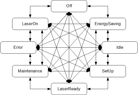
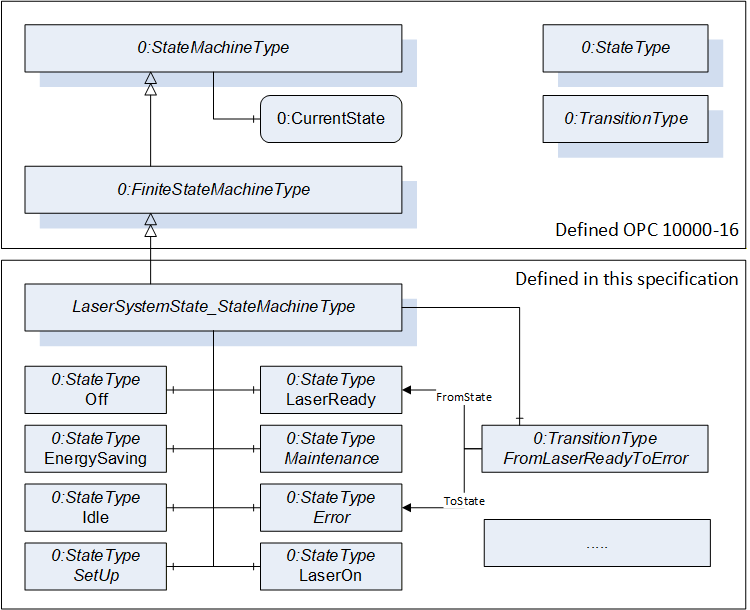
Figure 8 depicts how the LaserSystemState_StateMachineType is derived from the FiniteStateMachineType as defined in OPC 10000-16.
| Attribute | Value | ||||
| BrowseName | LaserSystemState_StateMachineType | ||||
| IsAbstract | False | ||||
| References | Node Class | BrowseName | DataType | TypeDefinition | Other |
|---|---|---|---|---|---|
| Subtype of the 0:FiniteStateMachineType defined in OPC 10000-16, i.e. inheriting the InstanceDeclarations of that Node. | |||||
| 0:HasProperty | Variable | 0:DefaultInstanceBrowseName | 0:QualifiedName | 0:PropertyType | |
| 0:HasComponent | Object | Off | 0:StateType | ||
| 0:HasComponent | Object | EnergySaving | 0:StateType | ||
| 0:HasComponent | Object | Idle | 0:StateType | ||
| 0:HasComponent | Object | SetUp | 0:StateType | ||
| 0:HasComponent | Object | LaserReady | 0:StateType | ||
| 0:HasComponent | Object | Maintenance | 0:StateType | ||
| 0:HasComponent | Object | Error | 0:StateType | ||
| 0:HasComponent | Object | LaserOn | 0:StateType | ||
| 0:HasComponent | Object | FromOffToOff | 0:TransitionType | ||
| 0:HasComponent | Object | FromOffToEnergySaving | 0:TransitionType | ||
| 0:HasComponent | Object | FromOffToIdle | 0:TransitionType | ||
| 0:HasComponent | Object | FromOffToSetUp | 0:TransitionType | ||
| 0:HasComponent | Object | FromOffToLaserReady | 0:TransitionType | ||
| 0:HasComponent | Object | FromOffToMaintenance | 0:TransitionType | ||
| 0:HasComponent | Object | FromOffToError | 0:TransitionType | ||
| 0:HasComponent | Object | FromOffToLaserOn | 0:TransitionType | ||
| 0:HasComponent | Object | FromEnergySavingToOff | 0:TransitionType | ||
| 0:HasComponent | Object | FromEnergySavingToEnergySaving | 0:TransitionType | ||
| 0:HasComponent | Object | FromEnergySavingToIdle | 0:TransitionType | ||
| 0:HasComponent | Object | FromEnergySavingToSetUp | 0:TransitionType | ||
| 0:HasComponent | Object | FromEnergySavingToLaserReady | 0:TransitionType | ||
| 0:HasComponent | Object | FromEnergySavingToMaintenance | 0:TransitionType | ||
| 0:HasComponent | Object | FromEnergySavingToError | 0:TransitionType | ||
| 0:HasComponent | Object | FromEnergySavingToLaserOn | 0:TransitionType | ||
| 0:HasComponent | Object | FromIdleToOff | 0:TransitionType | ||
| 0:HasComponent | Object | FromIdleToEnergySaving | 0:TransitionType | ||
| 0:HasComponent | Object | FromIdleToIdle | 0:TransitionType | ||
| 0:HasComponent | Object | FromIdleToSetUp | 0:TransitionType | ||
| 0:HasComponent | Object | FromIdleToLaserReady | 0:TransitionType | ||
| 0:HasComponent | Object | FromIdleToMaintenance | 0:TransitionType | ||
| 0:HasComponent | Object | FromIdleToError | 0:TransitionType | ||
| 0:HasComponent | Object | FromIdleToLaserOn | 0:TransitionType | ||
| 0:HasComponent | Object | FromSetUpToOff | 0:TransitionType | ||
| 0:HasComponent | Object | FromSetUpToEnergySaving | 0:TransitionType | ||
| 0:HasComponent | Object | FromSetUpToIdle | 0:TransitionType | ||
| 0:HasComponent | Object | FromSetUpToSetUp | 0:TransitionType | ||
| 0:HasComponent | Object | FromSetUpToLaserReady | 0:TransitionType | ||
| 0:HasComponent | Object | FromSetUpToMaintenance | 0:TransitionType | ||
| 0:HasComponent | Object | FromSetUpToError | 0:TransitionType | ||
| 0:HasComponent | Object | FromSetUpToLaserOn | 0:TransitionType | ||
| 0:HasComponent | Object | FromLaserReadyToOff | 0:TransitionType | ||
| 0:HasComponent | Object | FromLaserReadyToEnergySaving | 0:TransitionType | ||
| 0:HasComponent | Object | FromLaserReadyToIdle | 0:TransitionType | ||
| 0:HasComponent | Object | FromLaserReadyToSetUp | 0:TransitionType | ||
| 0:HasComponent | Object | FromLaserReadyToLaserReady | 0:TransitionType | ||
| 0:HasComponent | Object | FromLaserReadyToMaintenance | 0:TransitionType | ||
| 0:HasComponent | Object | FromLaserReadyToError | 0:TransitionType | ||
| 0:HasComponent | Object | FromLaserReadyToLaserOn | 0:TransitionType | ||
| 0:HasComponent | Object | FromMaintenanceToOff | 0:TransitionType | ||
| 0:HasComponent | Object | FromMaintenanceToEnergySaving | 0:TransitionType | ||
| 0:HasComponent | Object | FromMaintenanceToIdle | 0:TransitionType | ||
| 0:HasComponent | Object | FromMaintenanceToSetUp | 0:TransitionType | ||
| 0:HasComponent | Object | FromMaintenanceToLaserReady | 0:TransitionType | ||
| 0:HasComponent | Object | FromMaintenanceToMaintenance | 0:TransitionType | ||
| 0:HasComponent | Object | FromMaintenanceToError | 0:TransitionType | ||
| 0:HasComponent | Object | FromMaintenanceToLaserOn | 0:TransitionType | ||
| 0:HasComponent | Object | FromErrorToOff | 0:TransitionType | ||
| 0:HasComponent | Object | FromErrorToEnergySaving | 0:TransitionType | ||
| 0:HasComponent | Object | FromErrorToIdle | 0:TransitionType | ||
| 0:HasComponent | Object | FromErrorToSetUp | 0:TransitionType | ||
| 0:HasComponent | Object | FromErrorToLaserReady | 0:TransitionType | ||
| 0:HasComponent | Object | FromErrorToMaintenance | 0:TransitionType | ||
| 0:HasComponent | Object | FromErrorToError | 0:TransitionType | ||
| 0:HasComponent | Object | FromErrorToLaserOn | 0:TransitionType | ||
| 0:HasComponent | Object | FromLaserOnToOff | 0:TransitionType | ||
| 0:HasComponent | Object | FromLaserOnToEnergySaving | 0:TransitionType | ||
| 0:HasComponent | Object | FromLaserOnToIdle | 0:TransitionType | ||
| 0:HasComponent | Object | FromLaserOnToSetUp | 0:TransitionType | ||
| 0:HasComponent | Object | FromLaserOnToLaserReady | 0:TransitionType | ||
| 0:HasComponent | Object | FromLaserOnToMaintenance | 0:TransitionType | ||
| 0:HasComponent | Object | FromLaserOnToError | 0:TransitionType | ||
| 0:HasComponent | Object | FromLaserOnToLaserOn | 0:TransitionType | ||
| Conformance Units |
| LaserSystems LaserSystemState_StateMachineType Basic |
The States and Transitions define a StateMachine as shown in Figure 7. It does not define an initial State, i.e., the initial State is vendor-specific.
Note: None of the States or Transitions have a ModellingRule, i.e., they are only provided in the TypeDefinition, not on the instance. The CurrentState Variable (inherited from StateMachineType) contains the information of the current State of the instance.
Off is the state used to represent when a laser system is either completely shut down or in a system state below EnergySaving and thus very close to completely shut down (e.g., deep hibernation).
Note: In the Off state the OPC UA server of the laser system might actually not be reachable by an OPC UA client. However, by setting the Off state as part of the shutdown procedure an already connected client would know the last state was the Off state indicating that a normal shut down procedure was executed.
EnergySaving indicates that the energy consumption of the laser system is deliberately reduced. This can indicate a wide array of system states, reaching from close to the Off state (e.g., hibernation) to merely one or two elements of a laser system (e.g., a coolant pump) having reduced their power consumption.
Idle indicates that the laser system is not in an EnergySaving state, passively running while no preparing to achieve the LaserOn state and is thus also not in the SetUp state.
SetUp indicates that the system is currently actively doing something (e.g., bringing components to operating temperature) in order to achieve the LaserReady state.
LaserReady indicates that the laser system is merely missing a trigger before actively emitting radiation.
Maintenance indicates all states where the system is currently not able to operate due to for example software updates or hardware checkups.
Error indicates all states in which the system can currently not operate as an error is present. A closer description of the error can be taken form object instances described in chapter 7.3.
LaserOn is the only state in which the laser system is actively emitting radiation.
The components of the LaserSystemState_StateMachineType have additional references which are defined in Table 23.
| SourceBrowsePath | Reference Type | Is Forward | TargetBrowsePath |
| FromOffToOff | 0:FromState | True | Off |
| 0:ToState | True | Off | |
| FromOffToEnergySaving | 0:FromState | True | Off |
| 0:ToState | True | EnergySaving | |
| FromOffToIdle | 0:FromState | True | Off |
| 0:ToState | True | Idle | |
| FromOffToSetUp | 0:FromState | True | Off |
| 0:ToState | True | SetUp | |
| FromOffToLaserReady | 0:FromState | True | Off |
| 0:ToState | True | LaserReady | |
| FromOffToMaintenance | 0:FromState | True | Off |
| 0:ToState | True | Maintenance | |
| FromOffToError | 0:FromState | True | Off |
| 0:ToState | True | Error | |
| FromOffToLaserOn | 0:FromState | True | Off |
| 0:ToState | True | LaserOn | |
| FromEnergySavingToOff | 0:FromState | True | EnergySaving |
| 0:ToState | True | Off | |
| FromEnergySavingToEnergySaving | 0:FromState | True | EnergySaving |
| 0:ToState | True | EnergySaving | |
| FromEnergySavingToIdle | 0:FromState | True | EnergySaving |
| 0:ToState | True | Idle | |
| FromEnergySavingToSetUp | 0:FromState | True | EnergySaving |
| 0:ToState | True | SetUp | |
| FromEnergySavingToLaserReady | 0:FromState | True | EnergySaving |
| 0:ToState | True | LaserReady | |
| FromEnergySavingToMaintenance | 0:FromState | True | EnergySaving |
| 0:ToState | True | Maintenance | |
| FromEnergySavingToError | 0:FromState | True | EnergySaving |
| 0:ToState | True | Error | |
| FromEnergySavingToLaserOn | 0:FromState | True | EnergySaving |
| 0:ToState | True | LaserOn | |
| FromIdleToOff | 0:FromState | True | Idle |
| 0:ToState | True | Off | |
| FromIdleToEnergySaving | 0:FromState | True | Idle |
| 0:ToState | True | EnergySaving | |
| FromIdleToIdle | 0:FromState | True | Idle |
| 0:ToState | True | Idle | |
| FromIdleToSetUp | 0:FromState | True | Idle |
| 0:ToState | True | SetUp | |
| FromIdleToLaserReady | 0:FromState | True | Idle |
| 0:ToState | True | LaserReady | |
| FromIdleToMaintenance | 0:FromState | True | Idle |
| 0:ToState | True | Maintenance | |
| FromIdleToError | 0:FromState | True | Idle |
| 0:ToState | True | Error | |
| FromIdleToLaserOn | 0:FromState | True | Idle |
| 0:ToState | True | LaserOn | |
| FromSetUpToOff | 0:FromState | True | SetUp |
| 0:ToState | True | Off | |
| FromSetUpToEnergySaving | 0:FromState | True | SetUp |
| 0:ToState | True | EnergySaving | |
| FromSetUpToIdle | 0:FromState | True | SetUp |
| 0:ToState | True | Idle | |
| FromSetUpToSetUp | 0:FromState | True | SetUp |
| 0:ToState | True | SetUp | |
| FromSetUpToLaserReady | 0:FromState | True | SetUp |
| 0:ToState | True | LaserReady | |
| FromSetUpToMaintenance | 0:FromState | True | SetUp |
| 0:ToState | True | Maintenance | |
| FromSetUpToError | 0:FromState | True | SetUp |
| 0:ToState | True | Error | |
| FromSetUpToLaserOn | 0:FromState | True | SetUp |
| 0:ToState | True | LaserOn | |
| FromLaserReadyToOff | 0:FromState | True | LaserReady |
| 0:ToState | True | Off | |
| FromLaserReadyToEnergySaving | 0:FromState | True | LaserReady |
| 0:ToState | True | EnergySaving | |
| FromLaserReadyToIdle | 0:FromState | True | LaserReady |
| 0:ToState | True | Idle | |
| FromLaserReadyToSetUp | 0:FromState | True | LaserReady |
| 0:ToState | True | SetUp | |
| FromLaserReadyToLaserReady | 0:FromState | True | LaserReady |
| 0:ToState | True | LaserReady | |
| FromLaserReadyToMaintenance | 0:FromState | True | LaserReady |
| 0:ToState | True | Maintenance | |
| FromLaserReadyToError | 0:FromState | True | LaserReady |
| 0:ToState | True | Error | |
| FromLaserReadyToLaserOn | 0:FromState | True | LaserReady |
| 0:ToState | True | LaserOn | |
| FromMaintenanceToOff | 0:FromState | True | Maintenance |
| 0:ToState | True | Off | |
| FromMaintenanceToEnergySaving | 0:FromState | True | Maintenance |
| 0:ToState | True | EnergySaving | |
| FromMaintenanceToIdle | 0:FromState | True | Maintenance |
| 0:ToState | True | Idle | |
| FromMaintenanceToSetUp | 0:FromState | True | Maintenance |
| 0:ToState | True | SetUp | |
| FromMaintenanceToLaserReady | 0:FromState | True | Maintenance |
| 0:ToState | True | LaserReady | |
| FromMaintenanceToMaintenance | 0:FromState | True | Maintenance |
| 0:ToState | True | Maintenance | |
| FromMaintenanceToError | 0:FromState | True | Maintenance |
| 0:ToState | True | Error | |
| FromMaintenanceToLaserOn | 0:FromState | True | Maintenance |
| 0:ToState | True | LaserOn | |
| FromErrorToOff | 0:FromState | True | Error |
| 0:ToState | True | Off | |
| FromErrorToEnergySaving | 0:FromState | True | Error |
| 0:ToState | True | EnergySaving | |
| FromErrorToIdle | 0:FromState | True | Error |
| 0:ToState | True | Idle | |
| FromErrorToSetUp | 0:FromState | True | Error |
| 0:ToState | True | SetUp | |
| FromErrorToLaserReady | 0:FromState | True | Error |
| 0:ToState | True | LaserReady | |
| FromErrorToMaintenance | 0:FromState | True | Error |
| 0:ToState | True | Maintenance | |
| FromErrorToError | 0:FromState | True | Error |
| 0:ToState | True | Error | |
| FromErrorToLaserOn | 0:FromState | True | Error |
| 0:ToState | True | LaserOn | |
| FromLaserOnToOff | 0:FromState | True | LaserOn |
| 0:ToState | True | Off | |
| FromLaserOnToEnergySaving | 0:FromState | True | LaserOn |
| 0:ToState | True | EnergySaving | |
| FromLaserOnToIdle | 0:FromState | True | LaserOn |
| 0:ToState | True | Idle | |
| FromLaserOnToSetUp | 0:FromState | True | LaserOn |
| 0:ToState | True | SetUp | |
| FromLaserOnToLaserReady | 0:FromState | True | LaserOn |
| 0:ToState | True | LaserReady | |
| FromLaserOnToMaintenance | 0:FromState | True | LaserOn |
| 0:ToState | True | Maintenance | |
| FromLaserOnToError | 0:FromState | True | LaserOn |
| 0:ToState | True | Error | |
| FromLaserOnToLaserOn | 0:FromState | True | LaserOn |
| 0:ToState | True | LaserOn |
The component Variables of the LaserSystemState_StateMachineType have additional Attributes defined in Table 24
| Source Path | Value Attribute | Description Attribute |
| 0:DefaultInstanceBrowseName | LaserSystemState | The default BrowseName for instances of the type |
| Off | The laser system is currently off or very close to off | |
| EnergySaving | The laser system is actively reducing its energy consumption | |
| Idle | The laser system is operational but not perusing any activities to achieve the LaserReady state | |
| SetUp | The laser system is performing activities to achieve the LaserReady state | |
| LaserReady | The laser system is ready and is merely missing a trigger to actively emit radiation | |
| Maintenance | The laser system is currently not operational as maintenance is being performed on it | |
| Error | The laser system is not operational as it is in an error state | |
| LaserOn | The laser system is actively emitting radiation | |
| 0 | ||
| 1 | ||
| 2 | ||
| 3 | ||
| 4 | ||
| 5 | ||
| 6 | ||
| 7 | ||
| 0 | ||
| 1 | ||
| 2 | ||
| 3 | ||
| 4 | ||
| 5 | ||
| 6 | ||
| 7 | ||
| 8 | ||
| 9 | ||
| 10 | ||
| 11 | ||
| 12 | ||
| 13 | ||
| 14 | ||
| 15 | ||
| 16 | ||
| 17 | ||
| 18 | ||
| 19 | ||
| 20 | ||
| 21 | ||
| 22 | ||
| 23 | ||
| 24 | ||
| 25 | ||
| 26 | ||
| 27 | ||
| 28 | ||
| 29 | ||
| 30 | ||
| 31 | ||
| 32 | ||
| 33 | ||
| 34 | ||
| 35 | ||
| 36 | ||
| 37 | ||
| 38 | ||
| 39 | ||
| 40 | ||
| 41 | ||
| 42 | ||
| 43 | ||
| 44 | ||
| 45 | ||
| 46 | ||
| 47 | ||
| 48 | ||
| 49 | ||
| 50 | ||
| 51 | ||
| 52 | ||
| 53 | ||
| 54 | ||
| 55 | ||
| 56 | ||
| 57 | ||
| 58 | ||
| 59 | ||
| 60 | ||
| 61 | ||
| 62 | ||
| 63 |
7.2.5 ActivityDataMonitoring ObjectType Definition
The ActivityDataMonitoringType provides information about high-level logging of the activities performed on a laser system. This enables for example the tracking of configuration changes.
The ActivityDataMonitoringType is formally defined in Table 25.
| Attribute | Value | ||||
| BrowseName | ActivityDataMonitoringType | ||||
| IsAbstract | False | ||||
| References | Node Class | BrowseName | DataType | TypeDefinition | Other |
|---|---|---|---|---|---|
| Subtype of the 4:ElementMonitoringType defined in OPC 40501-1 i.e. inheriting the InstanceDeclarations of that Node. | |||||
| 0:HasProperty | Variable | ParameterIdentifier | 0:String | 0:PropertyType | M, RO |
| 0:HasComponent | Variable | PreviousValue | 0:Number | 0:AnalogUnitType | O, RO |
| 0:HasComponent | Variable | CurrentValue | 0:Number | 0:AnalogUnitType | M, RO |
| 0:HasComponent | Variable | Description | 0:LocalizedText | 0:BaseDataVariableType | O, RO |
| 0:HasInterface | ObjectType | 0:IOrderedObjectType | |||
| Applied from 0:IOrderedObjectType | |||||
| 0:HasProperty | Variable | 0:NumberInList | 0:UInt16 | 0:PropertyType | M, RO |
| Conformance Units | |||||
|---|---|---|---|---|---|
| LaserSystems ActivityDataMonitoringType Basic |
The 4:Name is a human-readable string containing the name of the configuration parameter, that is being changed. The uniqueness of this name cannot be assumed. The value of this Property may change during its life cycle.
ParameterIdentifier is a unique string identifier for a configuration parameter. The mandatory identifier is to be used to provide a unique ID. The value of this Property does not change during its life cycle.
The PreviousValue Component represents the value of the configuration parameter before a change, it is optional and given as number.
The CurrentValue Component represents the now current value of the of the configuration parameter in question, it is mandatory and given as number.
The optional Description Component represents a human-readable description of the configuration change.
Note: The change time stamp is given by the source time stamp of the node.
7.2.6 ConditionDataMonitoring ObjectType Definition
The ConditionDataMonitoringType provides specific information about current condition data of the laser system. Warning and error levels identify the specified working range of the monitored condition parameter.
The ConditionDataMonitoringType is formally defined in Table 26.
| Attribute | Value | ||||
| BrowseName | ConditionDataMonitoringType | ||||
| IsAbstract | False | ||||
| References | Node Class | BrowseName | DataType | TypeDefinition | Other |
|---|---|---|---|---|---|
| Subtype of the 4:ElementMonitoringType defined in OPC 40501-1 i.e. inheriting the InstanceDeclarations of that Node.… | |||||
| 0:HasProperty | Variable | ConditionParameterIdentifier | 0:String | 0:PropertyType | M, RO |
| 0:HasComponent | Variable | Value | 0:Number | 0:AnalogUnitType | M, RO |
| 0:HasComponent | Variable | UpperWarningLevel | 0:Number | 0:AnalogUnitType | O, RO |
| 0:HasComponent | Variable | UpperErrorLevel | 0:Number | 0:AnalogUnitType | O, RO |
| 0:HasComponent | Variable | LowerWarningLevel | 0:Number | 0:AnalogUnitType | O, RO |
| 0:HasComponent | Variable | LowerErrorLevel | 0:Number | 0:AnalogUnitType | O, RO |
| 0:HasComponent | Variable | Description | 0:LocalizedText | 0:BaseDataVariableType | O, RO |
| Conformance Units | |||||
|---|---|---|---|---|---|
| LaserSystems ConditionDataMonitoringType Basic |
The 4:Name Property represents a human-readable name of the monitored condition parameter. The uniqueness of this name cannot be assumed. The value of this Property may change during its life cycle. Examples are: “current temperature”, “power consumption”.
The mandatory ConditionParameterIdentifier is a unique string for identifying the monitored condition parameter. The Property is to be used to provide a unique ID, the value of which does not change during its life cycle.
The Value Component represents the current value of the monitored condition parameter. The Value is mandatory and given as number. The value should be updated frequently to match the current circumstances. Examples are: “2000”, “0.4563”, “-11”
UpperWarningLevel is a mandatory and given as number. This Component represents the upper limit for the monitored condition parameter above which a warning message is expected.
The mandatory UpperErrorLevel Component represents the maximum value permitted or the monitored condition parameter. If exceeded an error message is expected.
LowerWarningLevel is a mandatory and given as number. This Component represents the lower limit for the monitored condition parameter below which a warning message is expected.
The mandatory LowerErrorLevel Component represents the minimum value permitted for the monitored condition parameter. If exceeded an error message is expected.
The optional Description Component represents a human-readable description of the monitored condition parameter.
7.2.7 ConsumptionDataMonitoring ObjectType Definition
The ConsumptionDataMonitoringType provides information about the external media consumption (e.g., power consumption, compressed air, cooling water). This enables the identification of the consumables the laser system is equipped with.
The ConsumptionDataMonitoringType is formally defined in Table 27.
| Attribute | Value | ||||
| BrowseName | ConsumptionDataMonitoringType | ||||
| IsAbstract | False | ||||
| References | Node Class | BrowseName | DataType | TypeDefinition | Other |
|---|---|---|---|---|---|
| Subtype of the 4:ElementMonitoringType defined in OPC 40501-1 i.e. inheriting the InstanceDeclarations of that Node. | |||||
| 0:HasProperty | Variable | ConsumableIdentifier | 0:String | 0:PropertyType | M, RO |
| 0:HasComponent | Variable | Value | 0:Number | 0:AnalogUnitType | M, RO |
| 0:HasComponent | Variable | Description | 0:LocalizedText | 0:BaseDataVariableType | O, RO |
| Conformance Units |
| LaserSystems ConsumptionDataMonitoringType Basic |
The 4:Name is a human-readable string containing the name of the monitored media consumption parameter. The uniqueness of this name cannot be assumed based on this information. The value of this Property might change during its life cycle. Examples are: “power consumption”, “compressed air”, “cooling water”.
ConsumableIdentifier is a unique string identifier for a media consumption parameter. The mandatory Identifier is to be used to provide a unique ID. The value of this Property does not change during its life cycle.
The Value Component represents the current value of the monitored media consumption parameter. The Value is mandatory and given as number. The value should be updated frequently to match the represented current circumstances of the monitored media consumption parameter. Examples are: “2000”, “0.4563”, “-11”
The optional Description Component represents a human-readable description of the monitored media consumption parameter.