
1 Scope
For the communication between different machines, manufacturer independent information models are required. For woodworking machinery, these information models are based on OPC UA, a communication framework developed and provided by the OPC Foundation. While OPC UA provides the technology for the transfer of information, the definition which information is transferred in which form is defined in Companion Specifications.
This documentation defines a Companion Specification for general information regarding woodworking machines. The intention is that ObjectTypes which can be used for several machines and applications are defined only once.
2 Normative references
The following documents are referred to in the text in such a way that some or all of their content constitutes requirements of this document. For dated references, only the edition cited applies. For undated references, the latest edition of the referenced document (including any amendments and errata) applies.
OPC 10000-1, OPC Unified Architecture - Part 1: Overview and Concepts - V1.05.02
OPC 10000-1
OPC 10000-2, OPC Unified Architecture - Part 2: Security Model - V1.05.02
OPC 10000-2
OPC 10000-3, OPC Unified Architecture - Part 3: Address Space Model - V1.05.02
OPC 10000-3
OPC 10000-4, OPC Unified Architecture - Part 4: Services - V1.05.00
OPC 10000-4
OPC 10000-5, OPC Unified Architecture - Part 5: Information Model - V1.05.02
OPC 10000-5
OPC 10000-6, OPC Unified Architecture - Part 6: Mappings - V1.05.01
OPC 10000-6
OPC 10000-7, OPC Unified Architecture - Part 7: Profiles - V1.05.02
OPC 10000-7
OPC 10000-100, OPC Unified Architecture - Part 100: Devices - V1.04
OPC 10000-100
OPC 40001-1, OPC UA for Machinery - Part 1: Basic Building Blocks - V1.02.0
http://www.opcfoundation.org/UA/Machinery/
OPC 40001-3, OPC 40001-3 Machinery Job Mgmt - V1.0.1
https://opcfoundation.org/documents/40001-3/
3 Terms, definitions and conventions
3.1 Overview
It is assumed that basic concepts of OPC UA information modelling are understood in this specification. This specification will use these concepts to describe the Woodworking Information Model. For the purposes of this document, the terms and definitions given in OPC 10000-1, OPC 10000-3, OPC 10000-4, OPC 10000-5, OPC 10000-7, OPC 10000-100, OPC 40001-1 and OPC 40001-3 as well as the following apply.
3.2 OPC UA for Woodworking terms
3.2.1 Automatic mode
operational mode in which the machine operates in automatically without operator commands.
3.2.2 Axis
mechanical joint of a manipulator that performs a linear or a rotational movement
3.2.3 Maintenance
action for the achievement of machine-preserving measures
3.2.4 Manual activity
activity to be performed manually by the operator
3.2.5 Operator
person designated to start, monitor and stop the intended operation of a machine.
3.2.6 Run
the single, complete execution of a recipe
3.2.7 Tool
exchangeable components used in a machine to execute the production process
3.2.8 Tool change
Tool change in context of this interface is the action of inserting a tool into the machine. There are two reasons this is done or necessary: 1) tool life of one group of tools has expired and machining cannot continue until a new tool with sufficient tool life for the next operation is inserted (causing a tool change) 2) a tool for a given job is not available (or defined as "hand tool" and) must be provided.
3.3 Abbreviated terms
| CNC | Computerized Numerical Control |
| EUMABOIS | European Federation of Woodworking Machinery |
| KPI | Key Performance Indicator |
| OEE | Overall Equipment Effectiveness |
| PLC | Programmable Logic Controller |
3.4 Conventions used in this document
3.4.1 Conventions for Node descriptions
3.4.1.1 Node definitions
Node definitions are specified using tables (see Table 2).
Attributes are defined by providing the Attribute name and a value, or a description of the value.
References are defined by providing the ReferenceType name, the BrowseName of the TargetNode and its NodeClass.
If the TargetNode is a component of the Node being defined in the table the Attributes of the composed Node are defined in the same row of the table.
The DataType is only specified for Variables; "[<number>]" indicates a single-dimensional array, for multi-dimensional arrays the expression is repeated for each dimension (e.g. [2][3] for a two-dimensional array). For all arrays the ArrayDimensions is set as identified by <number> values. If no <number> is set, the corresponding dimension is set to 0, indicating an unknown size. If no number is provided at all the ArrayDimensions can be omitted. If no brackets are provided, it identifies a scalar DataType and the ValueRank is set to the corresponding value (see OPC 10000-3). In addition, ArrayDimensions is set to null or is omitted. If it can be Any or ScalarOrOneDimension, the value is put into "{<value>}", so either "{Any}" or "{ScalarOrOneDimension}" and the ValueRank is set to the corresponding value (see OPC 10000-3) and the ArrayDimensions is set to null or is omitted. Examples are given in Table 1.
| Notation | DataType | ValueRank | ArrayDimensions | Description |
| 0:Int32 | 0:Int32 | -1 | omitted or null | A scalar Int32. |
| 0:Int32[] | 0:Int32 | 1 | omitted or {0} | Single-dimensional array of Int32 with an unknown size. |
| 0:Int32[][] | 0:Int32 | 2 | omitted or {0,0} | Two-dimensional array of Int32 with unknown sizes for both dimensions. |
| 0:Int32[3][] | 0:Int32 | 2 | {3,0} | Two-dimensional array of Int32 with a size of 3 for the first dimension and an unknown size for the second dimension. |
| 0:Int32[5][3] | 0:Int32 | 2 | {5,3} | Two-dimensional array of Int32 with a size of 5 for the first dimension and a size of 3 for the second dimension. |
| 0:Int32{Any} | 0:Int32 | -2 | omitted or null | An Int32 where it is unknown if it is scalar or array with any number of dimensions. |
| 0:Int32{ScalarOrOneDimension} | 0:Int32 | -3 | omitted or null | An Int32 where it is either a single-dimensional array or a scalar. |
The TypeDefinition is specified for Objects and Variables.
The TypeDefinition column specifies a symbolic name for a NodeId, i.e. the specified Node points with a HasTypeDefinition Reference to the corresponding Node.
The ModellingRule of the referenced component is provided by specifying the symbolic name of the rule in the ModellingRule column. In the AddressSpace, the Node shall use a HasModellingRule Reference to point to the corresponding ModellingRule Object.
If the NodeId of a DataType is provided, the symbolic name of the Node representing the DataType shall be used.
Note that if a symbolic name of a different namespace is used, it is prefixed by the NamespaceIndex (see 3.4.2.2).
Nodes of all other NodeClasses cannot be defined in the same table; therefore, only the used ReferenceType, their NodeClass and their BrowseName are specified. A reference to another part of this document points to their definition. Table 2 illustrates the table. If no components are provided, the DataType, TypeDefinition and ModellingRule columns may be omitted and only a Comment column is introduced to point to the Node definition.
Each Type Node or well-known Instance Node defined shall have one or more ConformanceUnits defined in 8.1 that require the Node to be in the AddressSpace.
The relations between Nodes and ConformanceUnits are defined at the end of the tables defining Nodes, one row per ConformanceUnit. The ConformanceUnits are reflected in the Category element for the Node definition in the UANodeSet (see OPC 10000-6).
The list of ConformanceUnits in the UANodeSet allows Servers to optimize resource consumption by using a list of supported ConformanceUnits to select a subset of the Nodes in an Information Model.
When a Node is selected in this way, all dependencies implied by the References are also selected.
Dependencies exist if the Node is the source of HasTypeDefinition, HasInterface, HasAddIn or any HierarchicalReference. Dependencies also exist if the Node is the target of a HasSubtype Reference. For Variables and VariableTypes, the value of the DataType Attribute is a dependency. For DataType Nodes, any DataTypes referenced in the DataTypeDefinition Attribute are also dependencies.
For additional details see OPC 10000-5.
| Attribute | Value | ||||
| Attribute name | Attribute value. If it is an optional Attribute that is not set "--" will be used. | ||||
| References | NodeClass | BrowseName | DataType | TypeDefinition | Other |
|---|---|---|---|---|---|
| ReferenceType name | NodeClass of the target Node. | BrowseName of the target Node. | DataType of the referenced Node, only applicable for Variables. | TypeDefinition of the referenced Node, only applicable for Variables and Objects. | Additional characteristics of the TargetNode such as the ModellingRule or AccessLevel. |
| NOTE Notes referencing footnotes of the table content. | |||||
| Conformance Units | |||||
|---|---|---|---|---|---|
| Name of ConformanceUnit, one row per ConformanceUnit |
Components of Nodes can be complex that is containing components by themselves. The TypeDefinition, NodeClass and DataType can be derived from the type definitions, and the symbolic name can be created as defined in 3.4.3.1. Therefore, those containing components are not explicitly specified; they are implicitly specified by the type definitions.
The Other column defines additional characteristics of the Node. Examples of characteristics that can appear in this column are show in Table 3.
| Name | Short Name | Description |
| 0:Mandatory | M | The Node has the Mandatory ModellingRule. |
| 0:Optional | O | The Node has the Optional ModellingRule. |
| 0:MandatoryPlaceholder | MP | The Node has the MandatoryPlaceholder ModellingRule. |
| 0:OptionalPlaceholder | OP | The Node has the OptionalPlaceholder ModellingRule. |
| ReadOnly | RO | The Node AccessLevel has the CurrentRead bit set but not the CurrentWrite bit. |
| ReadWrite | RW | The Node AccessLevel has the CurrentRead and CurrentWrite bits set. |
| WriteOnly | WO | The Node AccessLevel has the CurrentWrite bit set but not the CurrentRead bit. |
If multiple characteristics are defined, they are separated by commas. The name or the short name may be used.
3.4.1.2 Additional References
To provide information about additional References, the format as shown in Table 4 is used.
| SourceBrowsePath | Reference Type | Is Forward | TargetBrowsePath |
| SourceBrowsePath is always relative to the TypeDefinition. Multiple elements are defined as separate rows of a nested table. | ReferenceType name | True = forward Reference | TargetBrowsePath points to another Node, which can be a well-known instance or a TypeDefinition. You can use BrowsePaths here as well, which is either relative to the TypeDefinition or absolute. If absolute, the first entry needs to refer to a type or well-known instance, uniquely identified within a namespace by the BrowseName. |
References can be to any other Node.
3.4.1.3 Additional sub-components
To provide information about sub-components, the format as shown in Table 5 is used.
| BrowsePath | Reference | NodeClass | BrowseName | DataType | TypeDefinition | Others |
| BrowsePath is always relative to the TypeDefinition. Multiple elements are defined as separate rows of a nested table | NOTE Same as for Table 2 | |||||
3.4.1.4 Additional Attribute values
The type definition table provides columns to specify the values for required Node Attributes for InstanceDeclarations. To provide information about additional Attributes, the format as shown in Table 6 is used.
| BrowsePath | <Attribute name> Attribute |
| BrowsePath is always relative to the TypeDefinition. Multiple elements are defined as separate rows of a nested table | The values of attributes are converted to text by adapting the reversible JSON encoding rules defined in OPC 10000-6. If the JSON encoding of a value is a JSON string or a JSON number then that value is entered in the value field. Double quotes are not included. If the DataType includes a NamespaceIndex (QualifiedNames, NodeIds or ExpandedNodeIds) then the notation used for BrowseNames is used. If the value is an Enumeration the name of the enumeration value is entered. If the value is a Structure then a sequence of name and value pairs is entered. Each pair is followed by a newline. The name is followed by a colon. The names are the names of the fields in the DataTypeDefinition. If the value is an array of non-structures then a sequence of values is entered where each value is followed by a newline. If the value is an array of Structures or a Structure with fields that are arrays or with nested Structures then the complete JSON array or JSON object is entered. |
There can be multiple columns to define more than one Attribute.
3.4.2 NodeIds and BrowseNames
3.4.2.1 NodeIds
The NodeIds of all Nodes described in this standard are only symbolic names. Annex A defines the actual NodeIds.
The symbolic name of each Node defined in this document is its BrowseName, or, when it is part of another Node, the BrowseName of the other Node, a ".", and the BrowseName of itself. In this case "part of" means that the whole has a HasProperty or HasComponent Reference to its part. Since all Nodes not being part of another Node have a unique name in this document, the symbolic name is unique.
The NamespaceUri for all NodeIds defined in this document is defined in Annex A. The NamespaceIndex for this NamespaceUri is vendor-specific and depends on the position of the NamespaceUri in the server namespace table.
Note that this document not only defines concrete Nodes, but also requires that some Nodes shall be generated, for example one for each Session running on the Server. The NodeIds of those Nodes are Server-specific, including the namespace. But the NamespaceIndex of those Nodes cannot be the NamespaceIndex used for the Nodes defined in this document, because they are not defined by this document but generated by the Server.
3.4.2.2 BrowseNames
The text part of the BrowseNames for all Nodes defined in this document is specified in the tables defining the Nodes. The NamespaceUri for all BrowseNames defined in this document is defined in 9.2.
For InstanceDeclarations of NodeClass Object and Variable that are placeholders (OptionalPlaceholder and MandatoryPlaceholder ModellingRule), the BrowseName and the DisplayName are enclosed in angle brackets (<>) as recommended in OPC 10000-3.
If the BrowseName is not defined by this document, a namespace index prefix is added to the BrowseName (e.g., prefix '0' leading to '0:EngineeringUnits' or prefix '2' leading to '2:DeviceRevision'). This is typically necessary if a Property of another specification is overwritten or used in the OPC UA types defined in this document. Table 53 provides a list of namespaces and their indexes as used in this document.
3.4.3 Common Attributes
3.4.3.1 General
The Attributes of Nodes, their DataTypes and descriptions are defined in OPC 10000-3. Attributes not marked as optional are mandatory and shall be provided by a Server. The following tables define if the Attribute value is defined by this specification or if it is server-specific.
For all Nodes specified in this specification, the Attributes named in Table 7 shall be set as specified in the table.
| Attribute | Value |
| DisplayName | The DisplayName is a LocalizedText. Each server shall provide the DisplayName identical to the BrowseName of the Node for the LocaleId "en". Whether the server provides translated names for other LocaleIds is server-specific. |
| Description | Optionally a server-specific description is provided. |
| NodeClass | Shall reflect the NodeClass of the Node. |
| NodeId | The NodeId is described by BrowseNames as defined in 3.4.2.1. |
| WriteMask | Optionally the WriteMask Attribute can be provided. If the WriteMask Attribute is provided, it shall set all non-server-specific Attributes to not writable. For example, the Description Attribute may be set to writable since a Server may provide a server-specific description for the Node. The NodeId shall not be writable, because it is defined for each Node in this specification. |
| UserWriteMask | Optionally the UserWriteMask Attribute can be provided. The same rules as for the WriteMask Attribute apply. |
| RolePermissions | Optionally server-specific role permissions can be provided. |
| UserRolePermissions | Optionally the role permissions of the current Session can be provided. The value is server-specifc and depend on the RolePermissions Attribute (if provided) and the current Session. |
| AccessRestrictions | Optionally server-specific access restrictions can be provided. |
3.4.3.2 Objects
For all Objects specified in this specification, the Attributes named in Table 8 shall be set as specified in the table. The definitions for the Attributes can be found in OPC 10000-3.
| Attribute | Value |
| EventNotifier | Whether the Node can be used to subscribe to Events or not is server-specific. |
3.4.3.3 Variables
For all Variables specified in this specification, the Attributes named in Table 9 shall be set as specified in the table. The definitions for the Attributes can be found in OPC 10000-3.
| Attribute | Value |
| MinimumSamplingInterval | Optionally, a server-specific minimum sampling interval is provided. |
| AccessLevel | The access level for Variables used for type definitions is server-specific, for all other Variables defined in this specification, the access level shall allow reading; other settings are server-specific. |
| UserAccessLevel | The value for the UserAccessLevel Attribute is server-specific. It is assumed that all Variables can be accessed by at least one user. |
| Value | For Variables used as InstanceDeclarations, the value is server-specific; otherwise it shall represent the value described in the text. |
| ArrayDimensions | If the ValueRank does not identify an array of a specific dimension (i.e. ValueRank <= 0) the ArrayDimensions can either be set to null or the Attribute is missing. This behaviour is server-specific. If the ValueRank specifies an array of a specific dimension (i.e. ValueRank > 0) then the ArrayDimensions Attribute shall be specified in the table defining the Variable. |
| Historizing | The value for the Historizing Attribute is server-specific. |
| AccessLevelEx | If the AccessLevelEx Attribute is provided, it shall have the bits 8, 9, and 10 set to 0, meaning that read and write operations on an individual Variable are atomic, and arrays can be partly written. |
3.4.3.4 VariableTypes
For all VariableTypes specified in this specification, the Attributes named in Table 10 shall be set as specified in the table. The definitions for the Attributes can be found in OPC 10000-3.
| Attributes | Value |
| Value | Optionally a server-specific default value can be provided. |
| ArrayDimensions | If the ValueRank does not identify an array of a specific dimension (i.e. ValueRank <= 0) the ArrayDimensions can either be set to null or the Attribute is missing. This behaviour is server-specific. If the ValueRank specifies an array of a specific dimension (i.e. ValueRank > 0) then the ArrayDimensions Attribute shall be specified in the table defining the VariableType. |
3.4.3.5 Methods
For all Methods specified in this specification, the Attributes named in Table 11 shall be set as specified in the table. The definitions for the Attributes can be found in OPC 10000-3.
| Attributes | Value |
| Executable | All Methods defined in this specification shall be executable (Executable Attribute set to "true"), unless it is defined differently in the Method definition. |
| UserExecutable | The value of the UserExecutable Attribute is server-specific. It is assumed that all Methods can be executed by at least one user. |
3.4.4 Structures
OPC 10000-3 differentiates between different kinds of Structures. The following conventions explain, how these Structures shall be defined.
The first kind are Structures without optional fields where none of the fields allows subtype (except fields with abstract DataTypes). Its definition is in Table 12.
| Name | Type | Description |
| <someStructure> | structure | Subtype of <someParentStructure> defined in … |
SP1 | 0:Byte[] | Setpoint 1 |
SP2 | 0:Byte[] | Setpoint 2 |
The second kind are Structures with optional fields where none of the fields allows subtypes (except fields with abstract DataTypes). Its definition is in Table 13.
Structures with fields that are optional have an "Optional" column. Fields that are optional have true set, otherwise False.
| Name | Type | Description | Optional |
| <someStructure> | structure | Subtype of <someParentStructure> defined in … | |
SP1 | 0:Byte[] | Setpoint 1 | False |
SP2 | 0:Byte[] | Setpoint 2 | True |
The third kind are Structures without optional fields where one or more of the fields allow subtypes. Its definition is in Table 14.
Structures with fields that allow subtypes have an "Allow Subtypes" column. Fields that allow subtypes have true set, otherwise False. Fields with abstract DataTypes can always be subtyped.
| Name | Type | Description |
Allow
SubTypes |
| <someStructure> | structure | Subtype of <someParentStructure> defined in … | |
SP1 | 0:Byte[] | Setpoint 1 | False |
Allow Subtypes | 0:ByteString | Some Bytestring | True |
4 General information to Woodworking and OPC UA
4.1 Introduction to Woodworking
EUMABOIS is the pan European industrial federation grouping 13 national associations which represent the major European manufacturers of machines, plants, tooling and ancillary equipment for the forestry and woodworking industries.
Encompassing some 850 industrial companies with a total turnover of 6 billion euro. The European industry can count on a work force of more than 35,000 employees. EUMABOIS members produce specialized machinery, cutting tools and auxiliary equipment for the forestry and primary timber processing sectors, incorporating plants for sawing, drying, veneer production, plywood and all timber-based boards and panels, e.g. chipboard, MDF, OSB, LVL panels.
EUMABOIS members manufacture standard and specialized machinery, plants and tooling for secondary processing for the production of all types of solid wood and panel products including furniture, chair frames, doors and windows.
Members also design, build and supply state of the art numerical control systems, sensors for robots and flexible manufacturing systems (FMS). Technologies that facilitate environmental protection and occupational safety within the woodworking industry and a comprehensive range of services complete the unique offer of the European manufacturers.
The mission of EUMABOIS is to facilitate a business environment (legislation, innovation, technology, environment, skilled workforce, financing, supply chain and infrastructure) to market the most competitive manufacturing solutions worldwide.
4.2 Introduction to OPC Unified Architecture
4.2.1 What is OPC UA?
OPC UA is an open and royalty free set of standards designed as a universal communication protocol. While there are numerous communication solutions available, OPC UA has key advantages:
A state of art security model (see OPC 10000-2).
A fault tolerant communication protocol.
An information modelling framework that allows application developers to represent their data in a way that makes sense to them.
OPC UA has a broad scope which delivers for economies of scale for application developers. This means that a larger number of high-quality applications at a reasonable cost are available. When combined with semantic models such as Woodworking, OPC UA makes it easier for end users to access data via generic commercial applications.
The OPC UA model is scalable from small devices to ERP systems. OPC UA Servers process information locally and then provide that data in a consistent format to any application requesting data - ERP, MES, PMS, Maintenance Systems, HMI, Smartphone or a standard Browser, for examples. For a more complete overview see OPC 10000-1.
4.2.2 Basics of OPC UA
As an open standard, OPC UA is based on standard internet technologies, like TCP/IP, HTTP, Web Sockets.
As an extensible standard, OPC UA provides a set of Services (see OPC 10000-4) and a basic information model framework. This framework provides an easy manner for creating and exposing vendor defined information in a standard way. More importantly all OPC UA Clients are expected to be able to discover and use vendor-defined information. This means OPC UA users can benefit from the economies of scale that come with generic visualization and historian applications. This specification is an example of an OPC UA Information Model designed to meet the needs of developers and users.
OPC UA Clients can be any consumer of data from another device on the network to browser based thin clients and ERP systems. The full scope of OPC UA applications is shown in Figure 1.

OPC UA provides a robust and reliable communication infrastructure having mechanisms for handling lost messages, failover, heartbeat, etc. With its binary encoded data, it offers a high-performing data exchange solution. Security is built into OPC UA as security requirements become more and more important especially since environments are connected to the office network or the internet and attackers are starting to focus on automation systems.
4.2.3 Information modelling in OPC UA
4.2.3.1 Concepts
OPC UA provides a framework that can be used to represent complex information as Objects in an AddressSpace which can be accessed with standard services. These Objects consist of Nodes connected by References. Different classes of Nodes convey different semantics. For example, a Variable Node represents a value that can be read or written. The Variable Node has an associated DataType that can define the actual value, such as a string, float, structure etc. It can also describe the Variable value as a variant. A Method Node represents a function that can be called. Every Node has a number of Attributes including a unique identifier called a NodeId and non-localized name called as BrowseName. An Object representing a 'Reservation' is shown in Figure 2.

Object and Variable Nodes represent instances and they always reference a TypeDefinition (ObjectType or VariableType) Node which describes their semantics and structure. Figure 3 illustrates the relationship between an instance and its TypeDefinition.
The type Nodes are templates that define all of the children that can be present in an instance of the type. In the example in Figure 3 the PersonType ObjectType defines two children: First Name and Last Name. All instances of PersonType are expected to have the same children with the same BrowseNames. Within a type the BrowseNames uniquely identify the children. This means Client applications can be designed to search for children based on the BrowseNames from the type instead of NodeIds. This eliminates the need for manual reconfiguration of systems if a Client uses types that multiple Servers implement.
OPC UA also supports the concept of sub-typing. This allows a modeller to take an existing type and extend it. There are rules regarding sub-typing defined in OPC 10000-3, but in general they allow the extension of a given type or the restriction of a DataType. For example, the modeller may decide that the existing ObjectType in some cases needs an additional Variable. The modeller can create a subtype of the ObjectType and add the Variable. A Client that is expecting the parent type can treat the new type as if it was of the parent type. Regarding DataTypes, subtypes can only restrict. If a Variable is defined to have a numeric value, a sub type could restrict it to a float.

References allow Nodes to be connected in ways that describe their relationships. All References have a ReferenceType that specifies the semantics of the relationship. References can be hierarchical or non-hierarchical. Hierarchical references are used to create the structure of Objects and Variables. Non-hierarchical are used to create arbitrary associations. Applications can define their own ReferenceType by creating subtypes of an existing ReferenceType. Subtypes inherit the semantics of the parent but may add additional restrictions. Figure 4 depicts several References, connecting different Objects.

The figures above use a notation that was developed for the OPC UA specification. The notation is summarized in Figure 5. UML representations can also be used; however, the OPC UA notation is less ambiguous because there is a direct mapping from the elements in the figures to Nodes in the AddressSpace of an OPC UA Server.

A complete description of the different types of Nodes and References can be found in OPC 10000-3 and the base structure is described in OPC 10000-5.
OPC UA specification defines a very wide range of functionality in its basic information model. It is not required that all Clients or Servers support all functionality in the OPC UA specifications. OPC UA includes the concept of Profiles, which segment the functionality into testable certifiable units. This allows the definition of functional subsets (that are expected to be implemented) within a companion specification. The Profiles do not restrict functionality, but generate requirements for a minimum set of functionality (see OPC 10000-7).
4.2.3.2 Namespaces
OPC UA allows information from many different sources to be combined into a single coherent AddressSpace. Namespaces are used to make this possible by eliminating naming and id conflicts between information from different sources. Each namespace in OPC UA has a globally unique string called a NamespaceUri which identifies a naming authority and a locally unique integer called a NamespaceIndex, which is an index into the Server's table of NamespaceUris. The NamespaceIndex is unique only within the context of a Session between an OPC UA Client and an OPC UA Server- the NamespaceIndex can change between Sessions and still identify the same item even though the NamespaceUri's location in the table has changed. The Services defined for OPC UA use the NamespaceIndex to specify the Namespace for qualified values.
There are two types of structured values in OPC UA that are qualified with NamespaceIndexes: NodeIds and QualifiedNames. NodeIds are locally unique (and sometimes globally unique) identifiers for Nodes. The same globally unique NodeId can be used as the identifier in a node in many Servers - the node's instance data may vary but its semantic meaning is the same regardless of the Server it appears in. This means Clients can have built-in knowledge of what the data means in these Nodes. OPC UA Information Models generally define globally unique NodeIds for the TypeDefinitions defined by the Information Model.
QualifiedNames are non-localized names qualified with a Namespace. They are used for the BrowseNames of Nodes and allow the same names to be used by different information models without conflict. TypeDefinitions are not allowed to have children with duplicate BrowseNames; however, instances do not have that restriction.
4.2.3.3 Companion Specifications
An OPC UA companion specification for an industry specific vertical market describes an Information Model by defining ObjectTypes, VariableTypes, DataTypes and ReferenceTypes that represent the concepts used in the vertical market, and potentially also well-defined Objects as entry points into the AddressSpace.
5 Use cases
5.1 Use case 1: Identification of Machines of different Manufacturers
The machines of different manufacturers shall be identifiable in a standardized manner. To realize this, a number of basic and static information like manufacturer name and model number are offered on the interface.
Links to related chapters:
7.1 Finding Woodworking Machines in a Server
7.2 WwMachineType ObjectType Definition
5.2 Use case 2: Overview of Machine States
The machines of different manufacturers offer their states in a standardized manner.
Links to related chapters:
7.3 IWwStateType InterfaceType Definition
7.4 IWwSubUnitsType InterfaceType Definition
7.5 IWwBaseStateType InterfaceType Definition
7.6 IWwUnitOverviewType InterfaceType Definition
7.9 IWwUnitFlagsType InterfaceType Definition
5.3 Use case 3: Overview of Machine Messages
The machine is expected to offer all current messages such as alarms, warnings and information over the interface. These errors and warnings shall be mapped to OPC UA event types accordingly.
Links to related chapters:
7.11 IWwEventMessageType InterfaceType Definition
7.12 WwEventCategoryEnumeration
7.13 WwMessageArgumentDataType
7.14 WwMessageArgumentValueDataType
7.15 WwBaseEventType ObjectType Definition
7.16 WwConditionType ObjectType Definition
7.17 WwAcknowledgeableConditionType ObjectType Definition
7.18 WwAlarmConditionType ObjectType Definition
7.19 WwEventsDispatcherType ObjectType
5.4 Use case 4: Providing Information for KPI calculations
To facilitate the calculation of different KPIs like for example OEE, the interface offers different item values with their changing times. These times allow to calculate the durations of different machine modes.
All of these relevant times are transferred with OPC UA mechanisms. Each state change is sent to the OPC UA Client, and the timestamp can be used to calculate the time durations needed for KPI compilation.
Link to related chapter:
7.10 IWwUnitValuesType InterfaceType Definition
5.5 Use case 5: Overview of Runtimes for a Job
In order to calculate cycle times and prognoses for production by an external system, the interface provides the time data of start, end, interruption and abortion of machining processes and programs on the machine.
Link to related chapter:
7.20 Job-Order-Input and Job-Order-Response Information
5.6 Use case 6: Overview of the Workpiece in a Job
Using the interface, an overview of the target and actual manufactured parts is possible. Additionally, it is possible to see which workpiece belong to which internal or customer order. If there is an irregularity in the process, which might affect the workpiece quality, the workpiece representation on the interface can be marked accordingly.
Link to related chapter:
7.20 Job-Order-Input and Job-Order-Response Information
5.7 Use case 7: Job Handling
A production manager wants to transfer and handle all necessary job data for a machine, i.e. transfer, modify, delete etc.
Link to related chapter:
7.20 Job-Order-Input and Job-Order-Response Information
5.8 Use case 8: Provide OPC UA for Machinery Use Cases
The Woodworking interface makes use of OPC 40001-1. It provides the MachineryBuildingBlocks folder, directly referencing all Machinery Building Blocks used by the Woodworking interface instance. In addition, the Woodworking interface incorporates OPC 40001-3. This specification provides the use cases for job management.
Link to related chapter:
7.2 WwMachineType ObjectType Definition
6 Woodworking Information Model overview
7 OPC UA Types and Interfaces
7.1 Finding Woodworking Machines in a Server
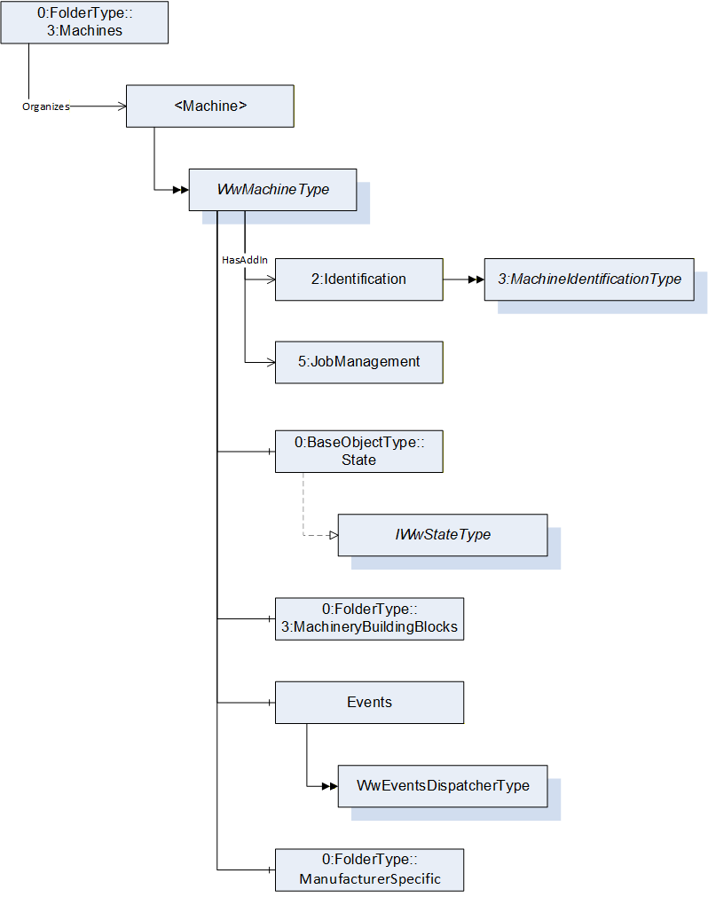
All instances of WwMachineType in a Server shall be referenced from the 3:Machines Object as defined in OPC 40001-1. This provides the capability to easily find all woodworking machines managed in a Server. The 3:Machines Object may contain other Nodes than instances of WwMachineType.
Each <Machine> Object represents an instance of a machine. In the simplest case, there is only one machine. The BrowseName of <Machine> should be unique within the Server. For woodworking machines it could be the 2:ProductInstanceUri of the 2:Identification Object of the 2:IVendorNameplateType.
7.2 WwMachineType ObjectType Definition
The WwMachineType represents a woodworking machine and is formally defined in Table 15. There may be non-woodworking machines with different types below the 3:Machines instance, too.
| Attribute | Value | ||||
| BrowseName | WwMachineType | ||||
| IsAbstract | False | ||||
| References | Node Class | BrowseName | DataType | TypeDefinition | Other |
|---|---|---|---|---|---|
| Subtype of the BaseObjectType defined in OPC 10000-5 | |||||
| Properties of the OPC UA for Machinery. | |||||
| 0:HasAddIn | Object | 2:Identification | 3:MachineIdentificationType | M | |
| 0:HasComponent | Object | 3:MachineryBuildingBlocks | 0:FolderType | O | |
| 0:HasAddIn | Object | 5:JobManagement | 5:JobManagementType | O | |
| Woodworking Properties | |||||
| 0:HasComponent | Object | State | 0:BaseObjectType | M | |
| 0:HasComponent | Object | Events | WwEventsDispatcherType | O | |
| 0:HasComponent | Object | ManufacturerSpecific | 0:FolderType | O | |
| Conformance Units | |||||
|---|---|---|---|---|---|
| Woodworking WwMachineType Mandatory Nodes | |||||
| Woodworking Machine Identification Writeable | |||||
| Woodworking JobManagement |
The 2:Identification Object provides identification information of the machine. It is specified in OPC 10000-100 and OPC 40001-1 (see chapter 2 Normative references).
The State Object provides information about the states of the machine.
The Events Object provides events.
The JobManagement Object provides functionality to add and control job orders. It also provides information about all job orders currently managed by the machine.
The ManufacturerSpecific Object provides manufacturer specific functionality.
The 3:MachineryBuildingBlocks Object contains all machinery building blocks. See Table 16 and Table 17 for more information.
| SourceBrowsePath | Reference Type | Is Forward | TargetBrowsePath |
| 3:MachineryBuildingBlocks | 0:HasAddIn | True | 2:Identification |
| 3:MachineryBuildingBlocks | 0:HasAddIn | True | 5:JobManagement |
The components of the WwMachineType have additional subcomponents which are defined in Table 17.
| Source Path | Reference | NodeClass | BrowseName | DataType | TypeDefinition | Others |
| State | 0:HasInterface | ObjectType | IWwStateType | |||
| Additional Properties for 2:Identification | ||||||
| 2:Identification | 0:HasProperty | Variable | LocationPlant | 0:String | 0:PropertyType | O, RO |
| 2:Identification | 0:HasProperty | Variable | LocationGPS | 0:String | 0:PropertyType | O, RO |
| 2:Identification | 0:HasProperty | Variable | CustomerCompanyName | 0:LocalizedText | 0:PropertyType | O, RO |
| Properties from 3:MachineIdentificationType and overwritten Mandatory Flags | ||||||
| 2:Identification | 0:HasProperty | Variable | 2:ProductInstanceUri | 0:String | 0:PropertyType | M, RO |
| 2:Identification | 0:HasProperty | Variable | 2:Manufacturer | 0:LocalizedText | 0:PropertyType | M, RO |
| 2:Identification | 0:HasProperty | Variable | 2:ManufacturerUri | 0:String | 0:PropertyType | O, RO |
| 2:Identification | 0:HasProperty | Variable | 2:Model | 0:LocalizedText | 0:PropertyType | M, RO |
| 2:Identification | 0:HasProperty | Variable | 2:ProductCode | 0:String | 0:PropertyType | O, RO |
| 2:Identification | 0:HasProperty | Variable | 2:HardwareRevision | 0:String | 0:PropertyType | O, RO |
| 2:Identification | 0:HasProperty | Variable | 2:SoftwareRevision | 0:String | 0:PropertyType | O, RO |
| 2:Identification | 0:HasProperty | Variable | 2:DeviceClass | 0:String | 0:PropertyType | M, RO |
| 2:Identification | 0:HasProperty | Variable | 2:SerialNumber | 0:String | 0:PropertyType | M, RO |
| 2:Identification | 0:HasProperty | Variable | 3:YearOfConstruction | 0:UInt16 | 0:PropertyType | M, RO |
| 2:Identification | 0:HasProperty | Variable | 3:MonthOfConstruction | 0:Byte | 0:PropertyType | O, RO |
| 2:Identification | 0:HasProperty | Variable | 3:InitialOperationDate | 0:DateTime | 0:PropertyType | O, RO |
| 2:Identification | 0:HasProperty | Variable | 2:AssetId | 0:String | 0:PropertyType | O, RW |
| 2:Identification | 0:HasProperty | Variable | 2:ComponentName | 0:LocalizedText | 0:PropertyType | O, RW |
| 2:Identification | 0:HasProperty | Variable | 3:Location | 0:String | 0:PropertyType | O, RW |
| Properties from folder 3:MachineryBuildingBlocks | ||||||
| 3:MachineryBuildingBlocks | 0:HasAddIn | Object | 3:MachineryItemState | 3:MachineryItemState_StateMachineType | O | |
| 3:MachineryBuildingBlocks | 0:HasAddIn | Object | 3:MachineryOperationMode | 3:MachineryOperationModeStateMachineType | O | |
The properties of the 3:MachineIdentificationType are listed here, too. The mandatory changes are marked bold.
The DeviceClass provides the classification of the machine. So far it is defined as follows for Woodworking:
"Other"
"SawingMachine"
"ProfilingMachine"
"EdgebandingMachine"
"BoringMachine"
"SandingMachine"
"MachiningCenter"
"Press"
"HandlingMachine"
The customer can set the following properties through the manufacturer HMI. Therefore, on the OPC UA interface they may be readable only.
The LocationPlant provides the location of the plant. This is the city where the machine is located, e.g. "Frankfurt".
The LocationGPS provides the location of the plant in GPS coordinates. The format is decimal degrees with north and east coordinates. For example, Hannover Messe has "52.3235858255059, 9.804918108600956".
Southern latitudes have a negative value, western longitudes as well. For example, Quito has the coordinates "-0.21975073282167099, -78.51255572531042".
The CustomerCompanyName provides the customer's name of the Woodworking manufacturer.
7.3 IWwStateType InterfaceType Definition
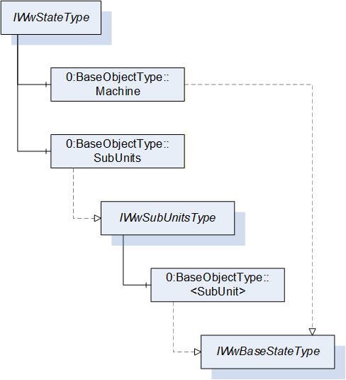
The IWwStateType provides the machine state and is formally defined in Table 18.
| Attribute | Value | ||||
| BrowseName | IWwStateType | ||||
| IsAbstract | True | ||||
| References | Node Class | BrowseName | DataType | TypeDefinition | Other |
|---|---|---|---|---|---|
| Subtype of the BaseInterfaceType defined in OPC 10000-5 | |||||
| 0:HasComponent | Object | Machine | 0:BaseObjectType | M | |
| 0:HasComponent | Object | SubUnits | 0:BaseObjectType | O | |
| Conformance Units | |||||
|---|---|---|---|---|---|
| Woodworking SubUnits Monitoring | |||||
| Woodworking Unit State |
Each instance of an IWwStateType represents an instance of a machine state. In the simplest case, there is only the Machine Object. The SubUnits Object is used when a machine has multiple states. For example, a CNC machine can have several places where independent jobs are produced.
The Machine state does not summarize the SubUnits states. It does not have to be based on the SubUnits states. It is a decision of the machine manufacturer.
The KPI calculation has to be done individually based on the special machine instance and its states.
The units of the IWwStateType have additional subunits which are defined in Table 19.
| Source Path | Reference | NodeClass | BrowseName | DataType | TypeDefinition | Others |
| Machine | 0:HasInterface | ObjectType | IWwBaseStateType | |||
| SubUnits | 0:HasInterface | ObjectType | IWwSubUnitsType |
7.4 IWwSubUnitsType InterfaceType Definition
The IWwSubUnitsType provides a list of SubUnits and is formally defined in Table 20.
| Attribute | Value | |||||
| BrowseName | IWwSubUnitsType | |||||
| IsAbstract | True | |||||
| References | Node Class | BrowseName | DataType | TypeDefinition | Other | |
|---|---|---|---|---|---|---|
| Subtype of the BaseInterfaceType defined in OPC 10000-5 | ||||||
| 0:HasComponent | Object | <SubUnit> | 0:BaseObjectType | MP | ||
| Conformance Units | ||||||
|---|---|---|---|---|---|---|
| Woodworking SubUnits Monitoring |
Each <SubUnit> object with Interface IWwBaseStateType shall be put into this object. It represents an instance of a state. For example, a CNC machine can have two places where independent jobs are produced. Then there are two <SubUnit> Objects. They may be named "Place_1" and "Place_2".
The components of the IWwSubUnitsType have additional subunits which are defined in Table 21.
| Source Path | Reference | Node Class | BrowseName | DataType | TypeDefinition | Others |
| <SubUnit> | 0:HasInterface | ObjectType | IWwBaseStateType |
7.5 IWwBaseStateType InterfaceType Definition
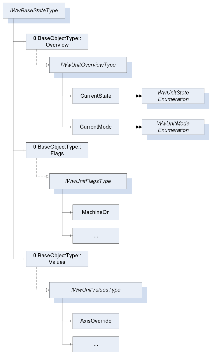
The IWwBaseStateType represents the state of a unit and is formally defined in Table 22. A unit can be a machine or part of a machine.
| Attribute | Value | ||||
| BrowseName | IWwBaseStateType | ||||
| IsAbstract | True | ||||
| References | Node Class | BrowseName | DataType | TypeDefinition | Other |
|---|---|---|---|---|---|
| Subtype of the BaseInterfaceType defined in OPC 10000-5 | |||||
| 0:HasComponent | Object | Overview | 0:BaseObjectType | M | |
| 0:HasComponent | Object | Flags | 0:BaseObjectType | O | |
| 0:HasComponent | Object | Values | 0:BaseObjectType | O | |
| Conformance Units | |||||
|---|---|---|---|---|---|
| Woodworking Machine Monitoring | |||||
| Woodworking SubUnits Monitoring | |||||
| Woodworking Unit State |
The Overview Object provides a general overview of the unit.
The Flags Object provides the flags of the unit.
The Values Object provides the counters and values of the unit.
The components of the IWwBaseStateType have additional subcomponents which are defined in Table 23.
| Source Path | Reference | NodeClass | BrowseName | DataType | TypeDefinition | Others |
| Overview | 0:HasInterface | ObjectType | IWwUnitOverviewType | |||
| Flags | 0:HasInterface | ObjectType | IWwUnitFlagsType | |||
| Values | 0:HasInterface | ObjectType | IWwUnitValuesType |
7.6 IWwUnitOverviewType InterfaceType Definition
The IWwUnitOverviewType represents the generalized overview of a unit and is formally defined in Table 24.
| Attribute | Value | ||||
| BrowseName | IWwUnitOverviewType | ||||
| IsAbstract | True | ||||
| References | Node Class | BrowseName | DataType | TypeDefinition | Other |
|---|---|---|---|---|---|
| Subtype of the BaseInterfaceType defined in OPC 10000-5 | |||||
| 0:HasComponent | Variable | CurrentState | WwUnitStateEnumeration | 0:BaseDataVariableType | M, RO |
| 0:HasComponent | Variable | CurrentMode | WwUnitModeEnumeration | 0:BaseDataVariableType | M, RO |
| Conformance Units | |||||
|---|---|---|---|---|---|
| Woodworking Unit State |
The CurrentState Variable provides the generalized state of the unit.
The CurrentMode Variable provides the generalized mode of the unit.
7.7 WwUnitStateEnumeration
This enumeration WwUnitStateEnumeration represents the generalized state of a unit. The enumeration is defined in Table 25.
| Name | Value | Description |
| OFFLINE | 0 | The unit is offline. |
| STANDBY | 1 | The unit is in standby. |
| READY | 2 | The unit is ready to start working. |
| WORKING | 3 | The unit is working. |
| ERROR | 4 | The unit is not able to work. The cause can be an alarm or error or user intervention. |
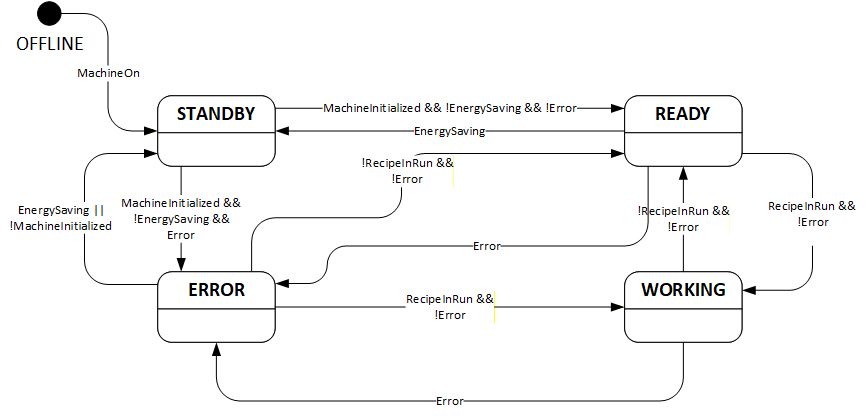
A unit state depends on the unit flags (see 7.9). Even if the unit flags are not provided in the AddressSpace they exist internally in the machine. If the device does not support EnergySaving, it is assumed that the variable value is False. Therefore, they are always the basis for the state:
OFFLINE:
| !MachineOn |
STANDBY:
| MachineOn && (!MachineInitialized || EnergySaving || (!Error && !Calibrated)) |
READY:
| MachineOn && MachineInitialized && !EnergySaving && !Error && Calibrated && !RecipeInRun |
WORKING:
| MachineOn && MachineInitialized && !EnergySaving && !Error && Calibrated && RecipeInRun |
ERROR:
| MachineOn && MachineInitialized && !EnergySaving && Error |
This is the state diagram of the UnitState:
Note: Since the unit state is an enumeration do not rely on the transitions. Only the logic of the unit flags counts.
Its representation in the AddressSpace is defined in Table 26.
| Attribute | Value | ||||
| BrowseName | WwUnitStateEnumeration | ||||
| IsAbstract | False | ||||
| References | Node Class | BrowseName | DataType | TypeDefinition | Other |
|---|---|---|---|---|---|
| Subtype of the Enumeration type defined in OPC 10000-5 | |||||
| 0:HasProperty | Variable | 0:EnumValues | 0:EnumValueType[] | 0:PropertyType | |
| Conformance Units | |||||
|---|---|---|---|---|---|
| Woodworking Unit State |
7.8 WwUnitModeEnumeration
This enumeration WwUnitModeEnumeration represents the generalized mode of a unit. The enumeration is defined in Table 27.
| Name | Value | Description |
| OTHER | 0 | This state is used if none of the other states below applies. |
| AUTOMATIC | 1 | The unit is in automatic mode. |
| SEMIAUTOMATIC | 2 | The unit is in semi-automatic mode. |
| MANUAL | 3 | The unit is in manual mode. |
| SETUP | 4 | The unit is in setup mode. |
| SLEEP | 5 | The unit is in sleep mode. Unit is still switched on, energy consumption reduced by e.g. reducing heating, switching drives off. Production is not possible. |
Its representation in the AddressSpace is defined in Table 28.
| Attribute | Value | ||||
| BrowseName | WwUnitModeEnumeration | ||||
| IsAbstract | False | ||||
| References | Node Class | BrowseName | DataType | TypeDefinition | Other |
|---|---|---|---|---|---|
| Subtype of the Enumeration type defined in OPC 10000-5 | |||||
| 0:HasProperty | Variable | 0:EnumValues | 0:EnumValueType[] | 0:PropertyType | |
| Conformance Units | |||||
|---|---|---|---|---|---|
| Woodworking Unit State |
7.9 IWwUnitFlagsType InterfaceType Definition
The IWwUnitFlagsType provides the flags of a unit and is formally defined in Table 29.
| Attribute | Value | ||||
| BrowseName | IWwUnitFlagsType | ||||
| IsAbstract | True | ||||
| References | Node Class | BrowseName | DataType | TypeDefinition | Other |
|---|---|---|---|---|---|
| Subtype of the BaseInterfaceType defined in OPC 10000-5 | |||||
| 0:HasComponent | Variable | MachineOn | 0:Boolean | 0:BaseDataVariableType | M, RO |
| 0:HasComponent | Variable | MachineInitialized | 0:Boolean | 0:BaseDataVariableType | M, RO |
| 0:HasComponent | Variable | PowerPresent | 0:Boolean | 0:BaseDataVariableType | M, RO |
| 0:HasComponent | Variable | AirPresent | 0:Boolean | 0:BaseDataVariableType | O, RO |
| 0:HasComponent | Variable | DustChipSuction | 0:Boolean | 0:BaseDataVariableType | O, RO |
| 0:HasComponent | Variable | Emergency | 0:Boolean | 0:BaseDataVariableType | M, RO |
| 0:HasComponent | Variable | Safety | 0:Boolean | 0:BaseDataVariableType | O, RO |
| 0:HasComponent | Variable | Calibrated | 0:Boolean | 0:BaseDataVariableType | M, RO |
| 0:HasComponent | Variable | Remote | 0:Boolean | 0:BaseDataVariableType | O, RO |
| 0:HasComponent | Variable | WorkpiecePresent | 0:Boolean | 0:BaseDataVariableType | O, RO |
| 0:HasComponent | Variable | Moving | 0:Boolean | 0:BaseDataVariableType | O, RO |
| 0:HasComponent | Variable | Error | 0:Boolean | 0:BaseDataVariableType | M, RO |
| 0:HasComponent | Variable | Alarm | 0:Boolean | 0:BaseDataVariableType | M, RO |
| 0:HasComponent | Variable | Warning | 0:Boolean | 0:BaseDataVariableType | M, RO |
| 0:HasComponent | Variable | Hold | 0:Boolean | 0:BaseDataVariableType | O, RO |
| 0:HasComponent | Variable | RecipeInRun | 0:Boolean | 0:BaseDataVariableType | M, RO |
| 0:HasComponent | Variable | RecipeInSetup | 0:Boolean | 0:BaseDataVariableType | O, RO |
| 0:HasComponent | Variable | RecipeInHold | 0:Boolean | 0:BaseDataVariableType | O, RO |
| 0:HasComponent | Variable | ManualActivityRequired | 0:Boolean | 0:BaseDataVariableType | O, RO |
| 0:HasComponent | Variable | LoadingEnabled | 0:Boolean | 0:BaseDataVariableType | O, RO |
| 0:HasComponent | Variable | WaitUnload | 0:Boolean | 0:BaseDataVariableType | O, RO |
| 0:HasComponent | Variable | WaitLoad | 0:Boolean | 0:BaseDataVariableType | O, RO |
| 0:HasComponent | Variable | EnergySaving | 0:Boolean | 0:BaseDataVariableType | O, RO |
| 0:HasComponent | Variable | ExternalEmergency | 0:Boolean | 0:BaseDataVariableType | O, RO |
| 0:HasComponent | Variable | MaintenanceRequired | 0:Boolean | 0:BaseDataVariableType | O, RO |
| 0:HasComponent | Variable | FeedRuns | 0:Boolean | 0:BaseDataVariableType | O, RO |
| Conformance Units | |||||
|---|---|---|---|---|---|
| Woodworking Machine Monitoring | |||||
| Woodworking SubUnits Monitoring | |||||
| Woodworking Unit State |
The MachineOn Variable is True if the machine is switched on. If the OPC UA Server runs on the machine this value is always True.
The MachineInitialized Variable is True if the MachineOn is True, the PLC and the control processes are running. The machine is ready for usage for the operator.
The PowerPresent Variable is True if the power supply is present (the drives are ready to move).
The AirPresent Variable is True if the air pressure is present in the machine.
The DustChipSuction Variable is True if the dust and chip suction is ready.
The Emergency Variable is True if at least one emergency button is pressed.
The Safety Variable is True if at least one safety device (light curtain, safety mat, …) has intervened.
The Calibrated Variable is True if all components of the machine that need to be calibrated are calibrated.
The Remote Variable is True if the machine is working with programs sent by the supervisor or other external application.
The WorkpiecePresent Variable is True if at least one piece is inside the machine.
The Moving Variable is True if at least one axis is moving.
The Error Variable is True if at least one reason exists which prevents the machine from working.
The Alarm Variable is True if at least one alarm exists.
The Warning Variable is True if at least one warning exists.
The Hold Variable is True if the movements are paused by the operator.
The RecipeInRun Variable is True if the machine runs its program. However, if the machine is paused by the program, the machine is considered to still be running its program, i.e. while the RecipeInHold Variable is True, the RecipeInRun cannot be False.
The RecipeInSetup Variable is True if the RecipeInRun is True and the machine is in the setup phase (example: automatic tool change).
The RecipeInHold Variable is True if the machine is paused by the program. This is only possible if the RecipeInRun Variable is also True.
The ManualActivityRequired Variable is True if a manual activity by the operator is required. The RecipeInRun is not affected.
The LoadingEnabled Variable is True if the unit is ready to get the next new part. If this is False no part can get into the unit.
The WaitUnload Variable is True if the machine is waiting to unload pieces.
The WaitLoad Variable is True if the machine is waiting for pieces.
The EnergySaving Variable is True if energy saving is activated on the machine.
The ExternalEmergency Variable is True if there is an emergency from the line controllercontroller.
The MaintenanceRequired Variable is True if maintenance is required.
The FeedRuns Variable is True if the feed is running on a throughfeed machine.
7.10 IWwUnitValuesType InterfaceType Definition
The IwwUnitValuesType represents the values of a unit and is formally defined in Table 30.
| Attribute | Value | ||||
| BrowseName | IWwUnitValuesType | ||||
| IsAbstract | True | ||||
| References | Node Class | BrowseName | DataType | TypeDefinition | Other |
|---|---|---|---|---|---|
| Subtype of the BaseInterfaceType defined in OPC 10000-5 | |||||
| 0:HasComponent | Variable | AxisOverride | 0:UInt32 | 0:BaseAnalogType | O, RO |
| 0:HasComponent | Variable | SpindleOverride | 0:UInt32 | 0:BaseAnalogType | O, RO |
| 0:HasComponent | Variable | FeedSpeed | 0:Double | 0:BaseAnalogType | O, RO |
| 0:HasComponent | Variable | ActualCycle | 0:Double | 0:BaseAnalogType | O, RO |
| 0:HasComponent | Variable | AbsoluteMachineOffTime | 0:UInt64 | 0:BaseAnalogType | O, RO |
| 0:HasComponent | Variable | AbsoluteStandbyTime | 0:UInt64 | 0:BaseAnalogType | O, RO |
| 0:HasComponent | Variable | RelativeStandbyTime | 0:UInt64 | 0:BaseAnalogType | O, RO |
| 0:HasComponent | Variable | AbsoluteReadyTime | 0:UInt64 | 0:BaseAnalogType | O, RO |
| 0:HasComponent | Variable | RelativeReadyTime | 0:UInt64 | 0:BaseAnalogType | O, RO |
| 0:HasComponent | Variable | AbsoluteWorkingTime | 0:UInt64 | 0:BaseAnalogType | O, RO |
| 0:HasComponent | Variable | RelativeWorkingTime | 0:UInt64 | 0:BaseAnalogType | O, RO |
| 0:HasComponent | Variable | AbsoluteErrorTime | 0:UInt64 | 0:BaseAnalogType | O, RO |
| 0:HasComponent | Variable | RelativeErrorTime | 0:UInt64 | 0:BaseAnalogType | O, RO |
| 0:HasComponent | Variable | AbsoluteMachineOnTime | 0:UInt64 | 0:BaseAnalogType | O, RO |
| 0:HasComponent | Variable | RelativeMachineOnTime | 0:UInt64 | 0:BaseAnalogType | O, RO |
| 0:HasComponent | Variable | AbsolutePowerPresentTime | 0:UInt64 | 0:BaseAnalogType | O, RO |
| 0:HasComponent | Variable | RelativePowerPresentTime | 0:UInt64 | 0:BaseAnalogType | O, RO |
| 0:HasComponent | Variable | AbsoluteProductionTime | 0:UInt64 | 0:BaseAnalogType | O, RO |
| 0:HasComponent | Variable | RelativeProductionTime | 0:UInt64 | 0:BaseAnalogType | O, RO |
| 0:HasComponent | Variable | AbsoluteProductionWithoutWorkpieceTime | 0:UInt64 | 0:BaseAnalogType | O, RO |
| 0:HasComponent | Variable | RelativeProductionWithoutWorkpieceTime | 0:UInt64 | 0:BaseAnalogType | O, RO |
| 0:HasComponent | Variable | AbsoluteProductionWaitWorkpieceTime | 0:UInt64 | 0:BaseAnalogType | O, RO |
| 0:HasComponent | Variable | RelativeProductionWaitWorkpieceTime | 0:UInt64 | 0:BaseAnalogType | O, RO |
| 0:HasComponent | Variable | AbsoluteRunsGood | 0:UInt64 | 0:BaseAnalogType | O, RO |
| 0:HasComponent | Variable | RelativeRunsGood | 0:UInt64 | 0:BaseAnalogType | O, RO |
| 0:HasComponent | Variable | AbsoluteRunsTotal | 0:UInt64 | 0:BaseAnalogType | O, RO |
| 0:HasComponent | Variable | RelativeRunsTotal | 0:UInt64 | 0:BaseAnalogType | O, RO |
| 0:HasComponent | Variable | AbsoluteRunsAborted | 0:UInt64 | 0:BaseAnalogType | O, RO |
| 0:HasComponent | Variable | RelativeRunsAborted | 0:UInt64 | 0:BaseAnalogType | O, RO |
| 0:HasComponent | Variable | AbsoluteLength | 0:UInt64 | 0:BaseAnalogType | O, RO |
| 0:HasComponent | Variable | RelativeLength | 0:UInt64 | 0:BaseAnalogType | O, RO |
| 0:HasComponent | Variable | AbsolutePiecesIn | 0:UInt64 | 0:BaseAnalogType | O, RO |
| 0:HasComponent | Variable | RelativePiecesIn | 0:UInt64 | 0:BaseAnalogType | O, RO |
| 0:HasComponent | Variable | AbsolutePiecesOut | 0:UInt64 | 0:BaseAnalogType | O, RO |
| 0:HasComponent | Variable | RelativePiecesOut | 0:UInt64 | 0:BaseAnalogType | O, RO |
| Conformance Units | |||||
|---|---|---|---|---|---|
| Woodworking Machine Monitoring | |||||
| Woodworking SubUnits Monitoring | |||||
| Woodworking Unit State |
Note: For OEE or KPI calculations the absolute and relative values might not be good enough. The term "Absolute" depends on the manufacturer. It may be reset on the machine or the InitialOperationDate is used for the start. The reset function can usually only be done by the service or the manufacturer. Therefore, it cannot be done by the OPC UA Client. Maybe one manufacturer has this feature.
The AxisOverride Variable provides the override for the axis in percent.
The SpindleOverride Variable provides the override for the spindle in percent.
The FeedSpeed Variable provides the feed speed in m/min for throughfeed machines. The values can be negative.
The ActualCycle Variable provides the parts per minutes.
The AbsoluteMachineOffTime can be calculated by the machine. The shutdown time and the starting time have to be stored on the machine.
The AbsoluteStandbyTime Variable provides the absolute time of the STANDBY state in msec.
The RelativeStandbyTime Variable provides the relative time since startup of the STANDBY state in msec.
The AbsoluteReadyTime Variable provides the absolute time of the READY state in msec.
The RelativeReadyTime Variable provides the relative time since startup of the READY state in msec.
The AbsoluteWorkingTime Variable provides the absolute time of the WORKING state in msec.
The RelativeWorkingTime Variable provides the relative time since startup of the WORKING state in msec.
The AbsoluteErrorTime Variable provides the absolute time of the ERROR state in msec.
The RelativeErrorTime Variable provides the relative time since startup of the ERROR state in msec.
The AbsoluteMachineOnTime Variable provides the absolute time in msec the machine is turned on based on the MachineOn state.
The RelativeMachineOnTime Variable provides the relative time in msec since startup the machine is turned on based on the MachineOn state.
The AbsolutePowerPresentTime Variable provides the absolute time in msec the machine has power on based on the PowerPresent state.
The RelativePowerPresentTime Variable provides the relative time in msec since startup the machine has power on based on the PowerPresent state.
The AbsoluteProductionTime Variable provides the absolute time in msec of the machine is working at least with one workpiece based on the RecipeInRun and WorkpiecePresent state.
The RelativeProductionTime Variable provides the relative time in msec since startup of the machine is working at least with one workpiece based on the RecipeInRun and WorkpiecePresent state.
The AbsoluteProductionWithoutWorkpieceTime Variable provides the absolute time in msec of the machine is working but without workpieces inside based on the RecipeInRun state and the negated WorkpiecePresent state.
The RelativeProductionWithoutWorkpieceTime Variable provides the relative time in msec since startup of the machine is working but without workpieces inside based on the RecipeInRun state and the negated WorkpiecePresent state.
The AbsoluteProductionWaitWorkpieceTime Variable provides the absolute time in msec of the machine is in working mode, bring the consent out to insert workpiece but no workpiece incoming from the previous machine based on the ReceipeInRun and WaitLoad state.
The RelativeProductionWaitWorkpieceTime Variable provides the relative time in msec waiting for workpieces since startup of the machine is in working mode, bring the consent out to insert workpiece but no workpiece incoming from the previous machine based on the ReceipeInRun and WaitLoad state.
The AbsoluteRunsGood Variable provides the absolute count of finished runs.
The RelativeRunsGood Variable provides the relative count of finished runs since the machine was last switched on.
The AbsoluteRunsTotal Variable provides the absolute count of total runs.
The RelativeRunsTotal Variable provides the relative count of total runs since the machine was last switched on.
The AbsoluteRunsAborted Variable provides the absolute count of aborted runs.
The RelativeRunsAborted Variable provides the relative count of aborted runs since the machine was last switched on.
The AbsoluteLength Variable provides the absolute produced length in mm.
The RelativeLength Variable provides the relative produced length in mm since the machine was last switched on.
The AbsolutePiecesIn Variable provides the absolute count of pieces which came into the machine.
The RelativePiecesIn Variable provides the relative count of pieces which came into the machine since the machine was last switched on.
The AbsolutePiecesOut Variable provides the absolute count of pieces which came out of the machine.
The RelativePiecesOut Variable provides the relative count of pieces which came out of the machine since the machine was last switched on.
7.11 IWwEventMessageType InterfaceType Definition
The IWwEventMessageType provides the common extensions for all events and conditions and is formally defined in Table 31. Each instance definition that includes this interface with a 0:HasInterface reference defines the predefined extensions.
| Attribute | Value | ||||
| BrowseName | IWwEventMessageType | ||||
| IsAbstract | True | ||||
| References | Node Class | BrowseName | DataType | TypeDefinition | Other |
|---|---|---|---|---|---|
| Subtype of the 0:BaseInterfaceType defined in OPC 10000-5 | |||||
| 0:HasProperty | Variable | EventCategory | WwEventCategoryEnumeration | 0:PropertyType | M, RO |
| 0:HasProperty | Variable | MessageId | 0:String | 0:PropertyType | M, RO |
| 0:HasProperty | Variable | MessageName | 0:String | 0:PropertyType | O, RO |
| 0:HasProperty | Variable | PathParts | 0:String[] | 0:PropertyType | M, RO |
| 0:HasProperty | Variable | Group | 0:String | 0:PropertyType | O, RO |
| 0:HasProperty | Variable | LocalizedMessages | 0:LocalizedText[] | 0:PropertyType | O, RO |
| 0:HasProperty | Variable | Arguments | WwMessageArgumentDataType[] | 0:PropertyType | O, RO |
| Conformance Units | |||||
|---|---|---|---|---|---|
| Woodworking Event Messages |
The EventCategory Variable provides the category of the event.
The MessageId Variable is a unique Identifier like a number or name of the message in the cause path (PathParts) determined Module. Example: "A4711" or "1".
The MessageName Variable is a short name like a number or title to reference a translation of the general message text. Example: "ID_MSG_EmergencyAlarm".
The PathParts Variable is an array of Path information strings based on a Server independent hierarchical structure of modules or an application specific expansion of that. It is an additional location information beside the SourceName. Example:
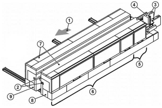
| Key | |
| 1 = Machine with feed direction 2 = Top pressure beam 3 = Chain beam 4 = Control 5 = Sizing with Milling 1 and Milling 2 inside 6 = Addition operation zone 7 = Integrated enclosure 8 = Fixed side 9 = Movable side |
| "Machine" | "FixedSide" | "Sizing" | "Milling1" |
The Group Variable specifies the class or group of the Message. The contents are set by the machine manufacturer. Examples are "safety", "emergency", "consumable".
The LocalizedMessages Variable contains an array of localized messages corresponding to the installed Server languages. The 0:Message property contains the content of the LocalizedMessages entry, which corresponds to the currently set language of the session. There are no placeholders in the messages. The 0:Message property and the LocalizedMessages are all resolved.
The Arguments Variable is an argument that can be used to parameterize the message. The number of the indexing in the array corresponds to the placeholder number in the message text. This ensures that the formatting functions of the implementations enable the localized message texts to be created. If a Client wants to use this feature, it has to use the MessageId. With this Id the raw message can be taken from a repository of the woodworking manufacturer. Then the placeholders can be resolved using the Arguments. The format of the raw message is up to the manufacturer.
7.12 WwEventCategoryEnumeration
This enumeration WwEventCategoryEnumeration represents the category of an event. The enumeration is defined in Table 32.
| Name | Value | Description |
| OTHER | 0 | No other event category applies or it is unknown. |
| DIAGNOSTIC | 1 | This category is used for messages for debugging and diagnostic purposes. They can be ignored by Clients (Diagnostic messages to operator, e.g. "system is ready") |
| INFORMATION | 2 | Messages of this category do not require a Client to read them for normal operation. The woodworking system can safely continue normal operation even if this message is ignored. (Help messages to operator, e.g. "select Auto mode and press Start") |
| WARNING | 3 | This category describes messages that in general could have moderate importance. Missing or ignoring such a message has no serious consequences. The woodworking system could request acknowledgement or acknowledgement and confirmation if needed. (Warning message to operator, e.g. "tool life will soon be reached") |
| ALARM | 4 | The goal of an alarm is to inform operators about conditions in a timely manner and allow the operator to take some action before some consequences occur. The consequences may be economic (product is not usable and must be discarded), may be physical (overheating), may be related to safety (fire or destruction could occur) or any of a number of other possibilities. Typically, if no action is taken related to an alarm for some period of time the process will cross some threshold at which point consequences will start to occur, likely causing an Error condition. According to this definition an alarm message usually requires an acknowledgement and it may be decided that also a confirmation is needed. |
| ERROR | 5 | This category is used for error messages associated with problems that need human interaction. An Error occurs if the situation has critical consequences for the machine process. For example, the protection of human life, of the environment, or of the machine itself, through safety mechanisms that block the process to prevent any harmful situation. This kind of situation cannot be solved automatically and confirmation by an operator is mandatory. |
This specification does not intend to determine in which manner acknowledgement and confirmation are given by operators: this could be done directly on a machine (e.g. through a SCADA or HMI) or/and by an OPC UA Client through OPC UA Alarms and Conditions mechanisms, if available.
Its representation in the AddressSpace is defined in Table 33.
| Attribute | Value | ||||
| BrowseName | WwEventCategoryEnumeration | ||||
| IsAbstract | False | ||||
| References | Node Class | BrowseName | DataType | TypeDefinition | Other |
|---|---|---|---|---|---|
| Subtype of the Enumeration type defined in OPC 10000-5 | |||||
| 0:HasProperty | Variable | 0:EnumValues | 0:EnumValueType[] | 0:PropertyType | |
| Conformance Units | |||||
|---|---|---|---|---|---|
| Woodworking Event Messages |
7.13 WwMessageArgumentDataType
This structure definition extends the argument structure with an argument value. The structure is defined in Table 34.
| Name | Type | Description |
| WwMessageArgumentDataType | structure | Subtype of the 0:Argument defined in OPC UA Part 3 |
Value | WwMessageArgumentValueDataType | The variable contains the value of the argument. |
Its representation in the AddressSpace is defined in Table 35.
| Attribute | Value | ||||
| BrowseName | WwMessageArgumentDataType | ||||
| IsAbstract | False | ||||
| References | Node Class | BrowseName | DataType | TypeDefinition | Other |
|---|---|---|---|---|---|
| Subtype of the 0:Argument defined in OPC UA Part 3 | |||||
| Conformance Units | |||||
|---|---|---|---|---|---|
| Woodworking Event Messages |
7.14 WwMessageArgumentValueDataType
This union defines the possible types of an argument value. The structure is defined in Table 36.
| Name | Type | Description |
| WwMessageArgumentValueDataType | structure | Subtype of the 0:Union defined in OPC UA Part 3 |
Array | WwMessageArgumentValueDataType[] | The content of the value as an array of the own type |
Boolean | Boolean | The content of the value as a boolean |
Int16 | Int16 | The content of the value as a 16 bit integer |
Int32 | Int32 | The content of the value as a 32 bit integer |
Int64 | Int64 | The content of the value as a 64 bit integer |
SByte | SByte | The content of the value as a 8 bit integer |
UInt16 | UInt16 | The content of the value as a 16 bit unsigned integer |
UInt32 | UInt32 | The content of the value as a 32 bit unsigned integer |
UInt64 | UInt64 | The content of the value as a 64 bit unsigned integer |
Byte | Byte | The content of the value as a 8 bit unsigned integer |
DateTime | DateTime | The content of the value as a datetime |
Guid | Guid | The content of the value as a GUID |
LocalizedText | LocalizedText | The content of the value as a localized text |
Double | Double | The content of the value as a double |
Float | Float | The content of the value as a float |
String | String | The content of the value as a string |
Other | String | The content of the value has no standard format and is instantiated as a string |
Its representation in the AddressSpace is defined in Table 37.
| Attribute | Value | ||||
| BrowseName | WwMessageArgumentValueDataType | ||||
| IsAbstract | False | ||||
| References | Node Class | BrowseName | DataType | TypeDefinition | Other |
|---|---|---|---|---|---|
| Subtype of the 0:Union defined in OPC UA Part 3 | |||||
| Conformance Units | |||||
|---|---|---|---|---|---|
| Woodworking Event Messages |
7.15 WwBaseEventType ObjectType Definition
The WwBaseEventType represents a message event from a module and is formally defined in Table 38.
| Attribute | Value | ||||
| BrowseName | WwBaseEventType | ||||
| IsAbstract | False | ||||
| References | Node Class | BrowseName | DataType | TypeDefinition | Other |
|---|---|---|---|---|---|
| Subtype of the 0:BaseEventType defined in OPC UA Part 5 | |||||
| 0:HasInterface | ObjectType | IWwEventMessageType | |||
| Applied from IWwEventMessageType | |||||
| 0:HasProperty | Variable | EventCategory | WwEventCategoryEnumeration | 0:PropertyType | M, RO |
| 0:HasProperty | Variable | MessageId | 0:String | 0:PropertyType | M, RO |
| 0:HasProperty | Variable | MessageName | 0:String | 0:PropertyType | O, RO |
| 0:HasProperty | Variable | PathParts | 0:String[] | 0:PropertyType | M, RO |
| 0:HasProperty | Variable | Group | 0:String | 0:PropertyType | O, RO |
| 0:HasProperty | Variable | LocalizedMessages | 0:LocalizedText[] | 0:PropertyType | O, RO |
| 0:HasProperty | Variable | Arguments | WwMessageArgumentDataType[] | 0:PropertyType | O, RO |
| Conformance Units | |||||
|---|---|---|---|---|---|
| Woodworking Event Messages |
IWwEventMessageType and its members are described in 7.11.
7.16 WwConditionType ObjectType Definition
The WwConditionType represents a stateful message event from a module and is formally defined in Table 39. It is used to classify conditions to recognize event messages with the extensions of the interface IWwEventMessageType. The 0:EnabledState of the linked condition is used to map the state of an event message. The behavior corresponds to the description of the 0:ConditionType defined in OPC UA Part 9.
| Attribute | Value | ||||
| BrowseName | WwConditionType | ||||
| IsAbstract | False | ||||
| References | Node Class | BrowseName | DataType | TypeDefinition | Other |
|---|---|---|---|---|---|
| Subtype of the 0:ConditionType defined in OPC UA Part 9 | |||||
| 0:HasInterface | ObjectType | IWwEventMessageType | |||
| Applied from IWwEventMessageType | |||||
| 0:HasProperty | Variable | EventCategory | WwEventCategoryEnumeration | 0:PropertyType | M, RO |
| 0:HasProperty | Variable | MessageId | 0:String | 0:PropertyType | M, RO |
| 0:HasProperty | Variable | MessageName | 0:String | 0:PropertyType | O, RO |
| 0:HasProperty | Variable | PathParts | 0:String[] | 0:PropertyType | M, RO |
| 0:HasProperty | Variable | Group | 0:String | 0:PropertyType | O, RO |
| 0:HasProperty | Variable | LocalizedMessages | 0:LocalizedText[] | 0:PropertyType | O, RO |
| 0:HasProperty | Variable | Arguments | WwMessageArgumentDataType[] | 0:PropertyType | O, RO |
| Conformance Units | |||||
|---|---|---|---|---|---|
| Woodworking Event Messages |
IWwEventMessageType and its members are described in 7.11.
7.17 WwAcknowledgeableConditionType ObjectType Definition
The WwAcknowledgeableConditionType represents a stateful message event from a module and is formally defined in Table 40. It is used to classify conditions to recognize acknowledgeable and confirmable event messages with the extensions of the interface IWwEventMessageType. The 0:EnabledState of the linked condition is used to map the active state of an event message. The behavior corresponds to the description of the 0:AcknowledgeableConditionType defined in OPC UA Part 9.
| Attribute | Value | ||||
| BrowseName | WwAcknowledgeableConditionType | ||||
| IsAbstract | False | ||||
| References | Node Class | BrowseName | DataType | TypeDefinition | Other |
|---|---|---|---|---|---|
| Subtype of the 0:AcknowledgeableConditionType defined in OPC UA Part 9 | |||||
| 0:HasInterface | ObjectType | IWwEventMessageType | |||
| Applied from IWwEventMessageType | |||||
| 0:HasProperty | Variable | EventCategory | WwEventCategoryEnumeration | 0:PropertyType | M, RO |
| 0:HasProperty | Variable | MessageId | 0:String | 0:PropertyType | M, RO |
| 0:HasProperty | Variable | MessageName | 0:String | 0:PropertyType | O, RO |
| 0:HasProperty | Variable | PathParts | 0:String[] | 0:PropertyType | M, RO |
| 0:HasProperty | Variable | Group | 0:String | 0:PropertyType | O, RO |
| 0:HasProperty | Variable | LocalizedMessages | 0:LocalizedText[] | 0:PropertyType | O, RO |
| 0:HasProperty | Variable | Arguments | WwMessageArgumentDataType[] | 0:PropertyType | O, RO |
| Conformance Units | |||||
|---|---|---|---|---|---|
| Woodworking Event Messages |
IWwEventMessageType and its members are described in 7.11.
7.18 WwAlarmConditionType ObjectType Definition
The WwAlarmConditionType represents a stateful message event from a module and is formally defined in Table 41. It is used to classify conditions to recognize acknowledgeable and confirmable event messages with the extensions of the interface IWwEventMessageType. As an enhancement to the more general conditions, an alarm contains an additional 0:ActiveState variable, which can be used to map the active state of an event message. In combination with this, the 0:EnabledState is used to control the usability of the condition. The behavior corresponds to the description of the 0:AlarmConditionType defined in OPC UA Part 9.
| Attribute | Value | ||||
| BrowseName | WwAlarmConditionType | ||||
| IsAbstract | False | ||||
| References | Node Class | BrowseName | DataType | TypeDefinition | Other |
|---|---|---|---|---|---|
| Subtype of the 0:AlarmConditionType defined in OPC UA Part 9 | |||||
| 0:HasInterface | ObjectType | IWwEventMessageType | |||
| Applied from IWwEventMessageType | |||||
| 0:HasProperty | Variable | EventCategory | WwEventCategoryEnumeration | 0:PropertyType | M, RO |
| 0:HasProperty | Variable | MessageId | 0:String | 0:PropertyType | M, RO |
| 0:HasProperty | Variable | MessageName | 0:String | 0:PropertyType | O, RO |
| 0:HasProperty | Variable | PathParts | 0:String[] | 0:PropertyType | M, RO |
| 0:HasProperty | Variable | Group | 0:String | 0:PropertyType | O, RO |
| 0:HasProperty | Variable | LocalizedMessages | 0:LocalizedText[] | 0:PropertyType | O, RO |
| 0:HasProperty | Variable | Arguments | WwMessageArgumentDataType[] | 0:PropertyType | O, RO |
| Conformance Units | |||||
|---|---|---|---|---|---|
| Woodworking Event Messages |
IWwEventMessageType and its members are described in 7.11.
7.19 WwEventsDispatcherType ObjectType
The WwEventsDispatcherType represents a container that is an event dispatcher for machine events and is formally defined in Table 42.
| Attribute | Value | ||||
| BrowseName | WwEventsDispatcherType | ||||
| IsAbstract | False | ||||
| References | Node Class | BrowseName | DataType | TypeDefinition | Other |
|---|---|---|---|---|---|
| Subtype of the 0:BaseObjectType defined in OPC 10000-5 | |||||
| 0:GeneratesEvent | ObjectType | 0:BaseEventType | |||
| 0:GeneratesEvent | ObjectType | WwBaseEventType | |||
| 0:GeneratesEvent | ObjectType | WwConditionType | |||
| 0:GeneratesEvent | ObjectType | WwAcknowledgeableConditionType | |||
| 0:GeneratesEvent | ObjectType | WwAlarmConditionType | |||
| Conformance Units | |||||
|---|---|---|---|---|---|
| Woodworking Machine Events | |||||
| Woodworking Event Propagation | |||||
| Woodworking Event Messages | |||||
| Woodworking Stateful Event Messages |
A wide variety of events and states can trigger messages on a plant, machine or component. Events and the associated messages are rather temporary and therefore cannot be subscribed directly. However, filtering can be realized with the event types like WwBaseEventType, WwConditionType, WwAcknowledgeableConditionType or WwAlarmConditionType. The woodworking events implement the interface IWwEventMessageType.
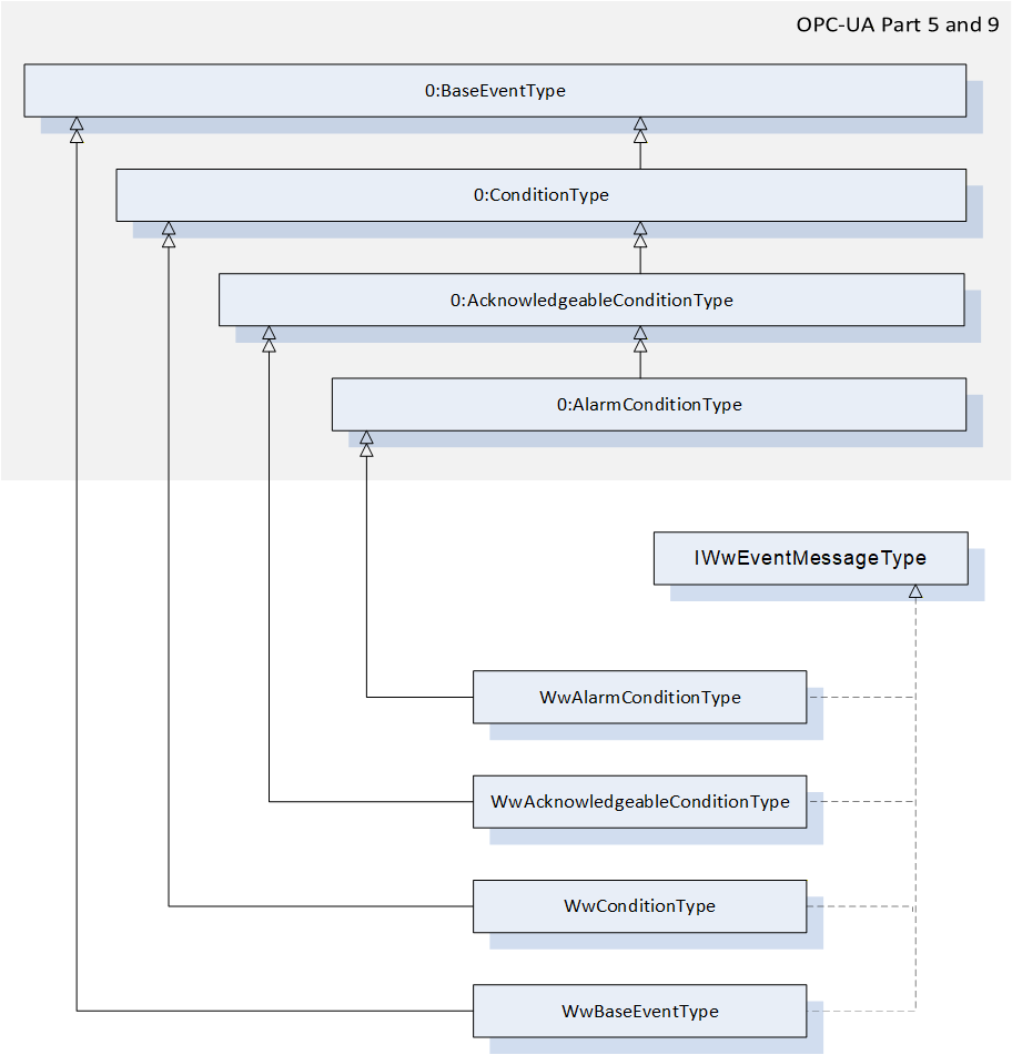
Woodworking machines do not need to provide the woodworking Types like WwBaseEventType. Instead, it can be an object based on any OPC UA 0:BaseEventType or a subtype, which also contains an implementation of the IWwEventMessageType interface. So it is possible to use the full range of OPC UA AlarmTypes like 0:LimitAlarmType:
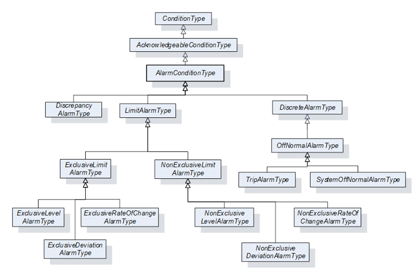
Note: Due to the implementation of the selected SDK (Software Developer Kit) to support the realization of the server application, it is possible that the condition methods such as AddComment, Acknowledge or Confirm cannot be used for conditions outside the AddressSpace.
7.20 Job-Order-Input and Job-Order-Response Information
7.20.1 Overview
This specification extends the standardized parameters of Job-Order-Input and Job-Order-Response Information of the OPC UA for Machinery, Part 3: JobManagement specification. All extended parameters have the Woodworking prefix "Ww" for the Id.
7.20.2 JobOrderParameters and JobResponseData
Table 43 lists the predefined key-value pairs for 2:JobOrderParameters and 2:JobResponseData. The table indicates, in which data structure the key-value pair should preferably to be used. An "X" in "In" indicates it may be used in 2:JobOrderParameters. And an "X" in "Out" indicates it may be used in 2:JobResponseData.
As an extension to "OPC40001-3" (OPC UA for Machinery, Part 3: JobManagement), all in-parameters can also be used as out-parameters. An in-parameter is normally set via a Manufacturing Execution System (MES) and an out-parameter is usually determined on a machine. In certain applications, this is determined jointly by the manufacturer and the customer.
| ID | DataType of Value | Description | EngineeringUnits | Sub-parameters | In | Out |
| WwSerialProduction | 0:Boolean | If this flag is set, production will continue until it is interrupted manually or by another reason. | - | - | X | - |
| WwProductionDatasetId | 0:String | Unique identification of the production dataset. Depending on the type of machine it can be: Program Recipe Macro etc. | - | - | X | - |
| WwRawLength | 0:Double | Raw length of the workpiece. If the dimension of a workpiece changes during the production process, then this raw value can be provided. The parameter is not required if the length does not change. | Product- specific | - | X | - |
| WwLength | 0:Double | Length of the workpiece. If the dimension of a workpiece changes during the production process, this is the resulting length. | Product- specific | - | X | - |
| WwRawWidth | 0:Double | Raw width of the workpiece. If the dimension of a workpiece changes during the production process, then this raw value can be provided. The parameter is not required if the width does not change. | Product- specific | - | X | - |
| WwWidth | 0:Double | Width of the workpiece. If the dimension of a workpiece changes during the production process, this is the resulting width. | Product- specific | - | X | - |
| WwRawHeight | 0:Double | Raw height of the workpiece. If the dimension of a workpiece changes during the production process, then this raw value can be provided. The parameter is not required if the height does not change. | Product- specific | - | X | - |
| WwHeight | 0:Double | Height of the workpiece. If the dimension of a workpiece changes during the production process, this is the resulting height. | Product- specific | - | X | - |
| WwProductionSubDatasetIds | 0:String[] | Array of unique sub-production dataset identifiers. If the order of the sub-production datasets has to be payed attention to, then the sequence within the array is relevant. Dependent on the type of machine it can be: SubProgram SubRecipe SubMacro etc. | - | - | X | - |
| WwPlannedFeedspeed | 0:Double | Planned feed speed. Planned movement speed of the workpieces in the machine. If WwPlannedCycle is also provided, the machine determines its use. | Product- specific | - | X | - |
| WwActualFeedspeed | 0:Double | Actual feed speed. Actual movement speed of the workpieces in the machine. | Product- specific | - | - | X |
| WwPlannedLoadingFeedspeed | 0:Double | Planned feed speed at the loading point. | Product- specific | - | X | - |
| WwActualLoadingFeedspeed | 0:Double | Actual feed speed at the loading point. | Product- specific | - | - | X |
| WwPlannedUnloadingFeedspeed | 0:Double | Planned feed speed at the unloading point. | Product- specific | - | X | - |
| WwActualUnloadingFeedspeed | 0:Double | Actual feed speed at the unloading point. | Product- specific | - | - | X |
| WwPlannedCycle | 0:Double | Planned production cycle. If WwPlannedFeedspeed is also provided, the machine determines its use. | Product- specific | - | X | - |
| WwActualCycle | 0:Double | Actual production cycle. | Product- specific | - | - | X |
| WwPlannedLoadingCycle | 0:Double | Planned production cycle at the loading point. If WwPlannedLoadingFeedspeed is also provided, the machine determines its use. | Product- specific | - | X | - |
| WwActualLoadingCycle | 0:Double | Actual production cycle at the loading point. | Product- specific | - | - | X |
| WwPlannedUnloadingCycle | 0:Double | Planned production cycle at the unloading point. If WwPlannedUnloadingFeedspeed is also provided, the machine determines its use. | Product- specific | - | X | - |
| WwActualUnloadingCycle | 0:Double | Actual production cycle at the unloading point. | Product- specific | - | - | X |
| WwPlannedRepair | 0:Boolean | Planned repair processing of a workpiece. (True = yes, False = no) If the incoming workpiece is to be repaired, this can be sent as an input. | - | - | X | - |
| WwRepair | 0:Boolean | Repair processing of a workpiece. (True = yes, False = no) This flag can be set to True as an output parameter if the quality of the workpiece after processing by the machine is not acceptable. | - | - | - | X |
| WwEdgeIds | 0:String[] | Ids of the edge material to be applied. | - | - | X | - |
| WwDischarge | 0:Boolean | Eject workpiece. (True = yes, False = no / back transport) | - | - | X | - |
| WwDischargeType | 0:UInt32 | Type of discharge 0 - not relevant 1 - manually 2 - automatically | - | - | X | - |
| WwLoadingType | 0:UInt32 | Type of loading 0 - not relevant 1 - manually 2 - automatically | - | - | X | - |
| WwBarcode | 0:String | Barcode. The content depends on the customer. It can be provided as an input parameter by the MES or as an output parameter by scanning it by a barcode reader. | - | - | X | X |
| WwWorkpieceMaterialIds | 0:String[] | E.g. type of wood: Possible example content: - "Spruce" - "Beech" - "HardWood" - etc | - | - | X | - |
| WwSurfaceIds | 0:String[] | Ids of the surface material to be applied | - | - | X | - |
| WwProcessing | 0:Boolean | True: The production step will be processed. False: No processing (e.g. in a Throughfeed machine, only transport) | - | - | X | - |
| WwFlipAngle | 0:UInt32 | Degrees to flip. 180° means flipping on the other side. | Product- specific | - | X | - |
| WwTurnAngle | 0:UInt32 | Degrees to turn, e.g. 90° | Product- specific | - | X | - |
| WwXMirror | 0:Boolean | False: No mirror True: Mirrored in X | - | - | X | - |
| WwYMirror | 0:Boolean | False: No mirror True: Mirrored in Y | - | - | X | - |
| WwPlannedProductionPlaceId | 0:String | Planned location where production has to take place, e.g. the number of the table on a CNC machine. | - | - | X | - |
| WwActualProductionPlaceId | 0:String | Actual location where the production took place, e.g. the number of the table on a CNC machine. | - | - | - | X |
| WwProductionMode | 0:String | Production mode to use. On the machine side different production modes can be defined by the user, (e.g. on a CNC machine "Mirrored" and "Place2" is equal to WwProductionMode 1) The MES can send this WwProductionMode with a job. | - | - | X | - |
| WwPlannedAmountOfInputWork pieces | 0:UInt32 | E.g. amount of panels for sawing machines | Product- specific | - | X | - |
8 Profiles and Conformance Units
8.1 Conformance Units
This chapter defines the corresponding Conformance Units for the OPC UA Information Model for Woodworking.
| Category | Title | Description |
| Server | Woodworking WwMachineType Mandatory Nodes | All nodes declared as mandatory in the WwMachineType are available in the AddressSpace. The nodes declared as optional may be included in the AddressSpace. Identification must not be writeable. |
| Server | Woodworking Machine Identification Writeable | If the writeable properties of the" WwMachineType Additional Subcomponents" are provided they must be writeable. If they are written the new value must be provided by the Server. The new value must still be provided by the Server after the restart. |
| Server | Woodworking Machine Monitoring | All nodes declared in the IWwUnitFlagsType and in IWwUnitValuesType may be included in the AddressSpace for the machines. |
| Server | Woodworking Machine Events | The Events node implementing the ObjectType WwEventsDispatcherType exists in the Address Space. |
| Server | Woodworking Custom Extensions Functionality | The folder node ManufacturerSpecific must exist below the <Machine> node (See Figure 6 - Overview of the OPC UA Woodworking information model) |
| Server | Woodworking SubUnits Monitoring | If subunits exist, the "SubUnits" node must be listed below the "State" node of a machine. For each unit an entry of the type "IWwBaseStateType" must exist. All nodes declared as mandatory in the IWwBaseStateType are available in the AddressSpace for each unit of the machine. The nodes declared as optional for this type may be included in the AddressSpace. |
| Server | Woodworking Unit State | In the machine or subunit the CurrentState of IWwUnitOverviewType and the Flags of IWwUnitFlagsType must exist. The CurrentState must be the result of the Flags as described in 7.7 WwUnitStateEnumeration. |
| Server | Woodworking Event Propagation | When Events are generated by a node, all nodes connected with inverse hierarchical References that have SubscribeToEvents set in the EventNotifier Attribute, shall also generate the Event. This propagates events over all inverse hierarchical References up to the instance of WwMachineType. Each instance of WwMachineType shall have SubscribeToEvents set in the EventNotifier Attribute and thus propagate all Events generated by nodes aggregated by this instance. |
| Server | Woodworking Event Messages | The Events node shall have SubscribeToEvents set in the EventNotifier Attribute. The Server supports event messages with all mandatory nodes declared in IWwEventMessageType. |
| Server | Woodworking Job Management | The Server supports the 5:Machinery Job Management Base Server Facet for base functionality of job management and optional job order input and job order response information. |
8.2 Profiles
8.2.1 Profile list
Table 45 lists all Profiles defined in this document and defines their URIs.
| Profile | URI |
| Woodworking Basic Server Profile | http://opcfoundation.org/UA/Woodworking/Server/Basic |
| Woodworking Monitoring Server Facet | http://opcfoundation.org/UA/Woodworking/Server/Monitoring |
| Woodworking Machine Events Server Facet | http://opcfoundation.org/UA/Woodworking/Server/MachineEvents |
| Woodworking Custom Extensions Server Facet | http://opcfoundation.org/UA/Woodworking/Server/CustomExtensions |
| Woodworking Job Management Server Facet | http://opcfoundation.org/UA/Woodworking/Server/JobManagement |
8.2.2 Server Facets
8.2.2.1 Overview
The following sections specify the Facets available for Servers that implement the Woodworking companion specification. Each section defines and describes a Facet or Profile.
8.2.2.2 Woodworking Basic Server Profile
Table 46 defines a Profile that describes the minimum required content and address space functionality any Woodworking Server shall at least provide.
| Group | Conformance Unit / Profile Title | Mandatory / Optional |
| Profile | 0: Micro Embedded Device 2017 Server Profile http://opcfoundation.org/UA-Profile/Server/MicroEmbeddedDevice2017 | M |
| Profile | 0:SecurityPolicy [B] - Basic256Sha256 Profile | M |
| Woodworking | Woodworking WwMachineType Mandatory Nodes | M |
| Woodworking | Woodworking Machine Identification Writeable | O |
| Profile | 3:Machinery Machine Identification Server Facet | M |
| Profile | 3:Machinery Building Block Organization | O |
| Profile | 3:Machinery State Server Facet | O |
8.2.2.3 Woodworking Monitoring Server Facet
Table 47 defines a Facet that provides a definition for monitoring the machine.
| Group | Conformance Unit / Profile Title | M / O |
| Woodworking | Woodworking Machine Monitoring | M |
| Woodworking | Woodworking SubUnits Monitoring | O |
| Woodworking | Woodworking Unit State | M |
8.2.2.4 Woodworking Machine Events Server Facet
Table 48 defines a Facet that provides a definition for providing messages to Clients.
| Group | Conformance Unit / Profile Title | M / O |
| Woodworking | Woodworking Machine Events | M |
| Woodworking | Woodworking Event Propagation | M |
| Woodworking | Woodworking Event Messages | M |
| Profile | 0:Standard Event Subscription Server Facet http://opcfoundation.org/UA-Profile/Server/StandardEventSubscription | M |
| Profile | 0:Address Space Notifier Server Facet http://opcfoundation.org/UA-Profile/Server/AddressSpaceNotifier | M |
8.2.2.5 Woodworking Custom Extension Server Facet
Table 49 defines a Facet that provides customer specific functionality.
| Group | Conformance Unit / Profile Title | M / O |
| Woodworking | Woodworking Custom Extensions Functionality | M |
8.2.2.6 Woodworking Job Management Server Facet
Table 50 defines a Facet that describes a Server that provides the functionality of job management for woodworking machines.
| Group | Conformance Unit / Profile Title | M / O |
| Profile | 5:Machinery Job Management Base Server Facet http://opcfoundation.org/UA-Profile/Machinery/Jobs/Server/Base | |
| Woodworking | Woodworking Job Management | O |
9 Namespaces
9.1 Namespace Metadata
Table 51 defines the namespace metadata for this document. The Object is used to provide version information for the namespace and an indication about static Nodes. Static Nodes are identical for all Attributes in all Servers, including the Value Attribute. See OPC 10000-5 for more details.
The information is provided as Object of type NamespaceMetadataType. This Object is a component of the Namespaces Object that is part of the Server Object. The NamespaceMetadataType ObjectType and its Properties are defined in OPC 10000-5.
The version information is also provided as part of the ModelTableEntry in the UANodeSet XML file. The UANodeSet XML schema is defined in OPC 10000-6.
| Attribute | Value | |||
| BrowseName | http://opcfoundation.org/UA/Woodworking/ | |||
| Property | DataType | Value | |
|---|---|---|---|
| NamespaceUri | String | http://opcfoundation.org/UA/Woodworking/ | |
| NamespaceVersion | String | 1.02.0 | |
| NamespacePublicationDate | DateTime | 6/1/2025 1:02:00 AM | |
| IsNamespaceSubset | Boolean | False | |
| StaticNodeIdTypes | IdType [] | System.Int32[] | |
| StaticNumericNodeIdRange | NumericRange [] | ||
| StaticStringNodeIdPattern | String | ||
9.2 Handling of OPC UA Namespaces
Namespaces are used by OPC UA to create unique identifiers across different naming authorities. The Attributes NodeId and BrowseName are identifiers. A Node in the UA AddressSpace is unambiguously identified using a NodeId. Unlike NodeIds, the BrowseName cannot be used to unambiguously identify a Node. Different Nodes may have the same BrowseName. They are used to build a browse path between two Nodes or to define a standard Property.
Servers may often choose to use the same namespace for the NodeId and the BrowseName. However, if they want to provide a standard Property, its BrowseName shall have the namespace of the standards body although the namespace of the NodeId reflects something else, for example the EngineeringUnits Property. All NodeIds of Nodes not defined in this document shall not use the standard namespaces.
Table 52 provides a list of mandatory and optional namespaces used in a Woodworking OPC UA Server.
| NamespaceURI | Description |
| http://opcfoundation.org/UA/ | Namespace for NodeIds and BrowseNames defined in the OPC UA specification. This namespace shall have namespace index 0. |
| Local Server URI | Namespace for nodes defined in the local Server. This may include types and instances used in Woodworking machine represented by the Server. This namespace shall have namespace index 1. |
| http://opcfoundation.org/UA/DI/ | Namespace for NodeIds and BrowseNames defined in OPC Unified Architecture Part 100: Devices (OPC 10000-100). The namespace index is Server specific. |
| http://opcfoundation.org/UA/Machinery/ | Namespace for NodeIds and BrowseNames defined in OPC UA for Machinery Part 1: Basic Building Blocks (OPC 40001-1). The namespace index is Server specific. |
| http://opcfoundation.org/UA/Woodworking/ | Namespace for NodeIds and BrowseNames defined in this document. The namespace index is Server specific. |
| http://opcfoundation.org/UA/ISA95-JOBCONTROL_V2/ | Namespace for NodeIds and BrowseNames defined in OPC UA for ISA-95 Part 4: Job Control (OPC 10031-4). The namespace index is Server specific. |
| http://opcfoundation.org/UA/Machinery/Jobs/ | Namespace for NodeIds and BrowseNames defined in OPC UA for Machinery Part 3: Job Management (OPC 40001-3). The namespace index is Server specific. |
Table 53 provides a list of namespaces and their indices used for BrowseNames in this document. The default namespace of this document is not listed since all BrowseNames without prefix use this default namespace.
| NamespaceURI | Namespace Index | Example |
| http://opcfoundation.org/UA/ | 0 | 0:EngineeringUnits |
| http://opcfoundation.org/UA/DI/ | 2 | 2:DeviceRevision |
| http://opcfoundation.org/UA/Machinery/ | 3 | 3:YearOfConstruction |
| http://opcfoundation.org/UA/ISA95-JOBCONTROL_V2/ | 4 | 4:ISA95ParameterDataType |
| http://opcfoundation.org/UA/Machinery/Jobs/ | 5 | 5:ProcessIrregularity |
Annex A Woodworking Namespace and mappings (Normative)
A.1 NodeSet and supplementary files for Woodworking Information Model
The Woodworking Information Model is identified by the following URI:
http://opcfoundation.org/UA/Woodworking/
Documentation for the NamespaceUri can be found here.
The NodeSet associated with this version of specification can be found here:
The NodeSet associated with the latest version of the specification can be found here:
https://reference.opcfoundation.org/nodesets/?u=http://opcfoundation.org/UA/Woodworking/&i=1
Supplementary files for the Woodworking Information Model can be found here:
The files associated with the latest version of the specification can be found here:
https://reference.opcfoundation.org/nodesets/?u=http://opcfoundation.org/UA/Woodworking/&i=2
___________
Annex B Examples (Informative)
B.1 Overview
This appendix provides an informal example on how the building blocks defined in the machinery specification can be used.
| B.2 | Finding Machines |
In Figure 13, an example is given, showing the finding all Machines in Server use cases. The Server provides information about an Edge Banding as well as a CNC machine defined by Woodworking.
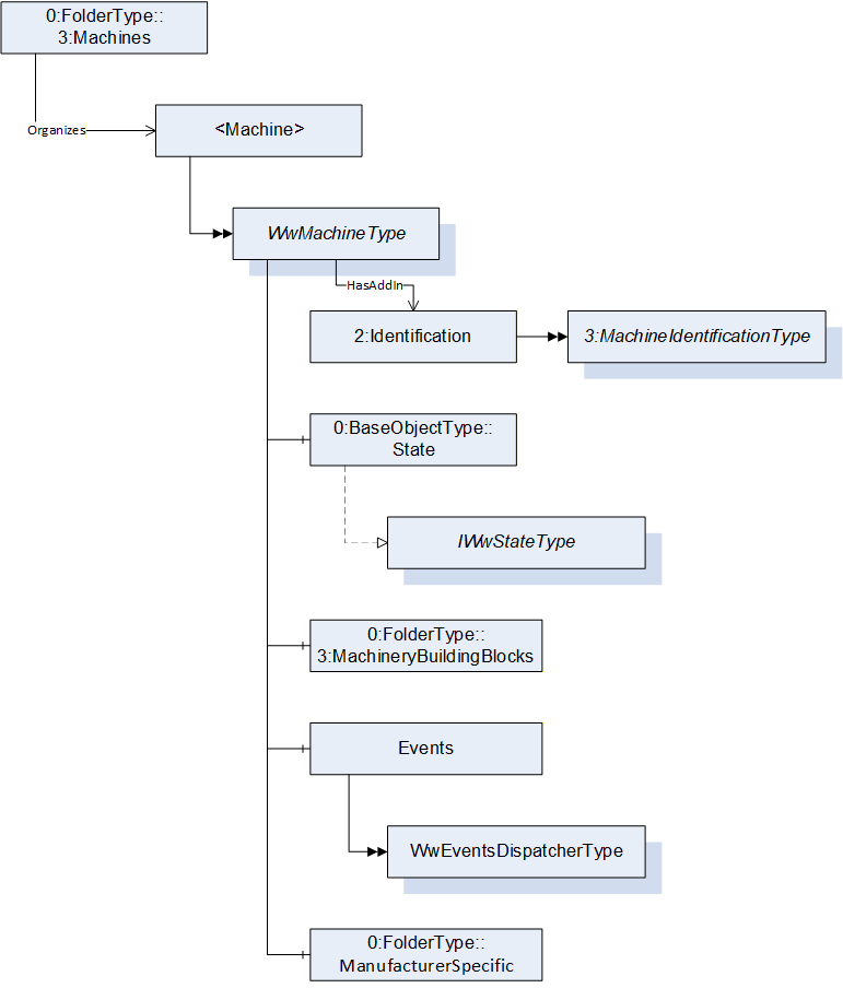
___________
Agreement of Use
COPYRIGHT RESTRICTIONS
This document is provided "as is" by the OPC Foundation and VDMA.
Right of use for this specification is restricted to this specification and does not grant rights of use for referred documents.
Right of use for this specification will be granted without cost.
This document may be distributed through computer systems, printed or copied as long as the content remains unchanged and the document is not modified.
OPC Foundation and VDMA do not guarantee usability for any purpose and shall not be made liable for any case using the content of this document.
The user of the document agrees to indemnify OPC Foundation and VDMA and their officers, directors and agents harmless from all demands, claims, actions, losses, damages (including damages from personal injuries), costs and expenses (including attorneys' fees) which are in any way related to activities associated with its use of content from this specification.
The document shall not be used in conjunction with company advertising, shall not be sold or licensed to any party.
The intellectual property and copyright is solely owned by the OPC Foundation and VDMA.
PATENTS
The attention of adopters is directed to the possibility that compliance with or adoption of OPC or VDMA specifications may require use of an invention covered by patent rights. OPC Foundation or VDMA shall not be responsible for identifying patents for which a license may be required by any OPC or VDMA specification, or for conducting legal inquiries into the legal validity or scope of those patents that are brought to its attention. OPC or VDMA specifications are prospective and advisory only. Prospective users are responsible for protecting themselves against liability for infringement of patents.
WARRANTY AND LIABILITY DISCLAIMERS
WHILE THIS PUBLICATION IS BELIEVED TO BE ACCURATE, IT IS PROVIDED "AS IS" AND MAY CONTAIN ERRORS OR MISPRINTS. THE OPC FOUDATION NOR VDMA MAKES NO WARRANTY OF ANY KIND, EXPRESSED OR IMPLIED, WITH REGARD TO THIS PUBLICATION, INCLUDING BUT NOT LIMITED TO ANY WARRANTY OF TITLE OR OWNERSHIP, IMPLIED WARRANTY OF MERCHANTABILITY OR WARRANTY OF FITNESS FOR A PARTICULAR PURPOSE OR USE. IN NO EVENT SHALL THE OPC FOUNDATION NOR VDMA BE LIABLE FOR ERRORS CONTAINED HEREIN OR FOR DIRECT, INDIRECT, INCIDENTAL, SPECIAL, CONSEQUENTIAL, RELIANCE OR COVER DAMAGES, INCLUDING LOSS OF PROFITS, REVENUE, DATA OR USE, INCURRED BY ANY USER OR ANY THIRD PARTY IN CONNECTION WITH THE FURNISHING, PERFORMANCE, OR USE OF THIS MATERIAL, EVEN IF ADVISED OF THE POSSIBILITY OF SUCH DAMAGES.
The entire risk as to the quality and performance of software developed using this specification is borne by you.
RESTRICTED RIGHTS LEGEND
This Specification is provided with Restricted Rights. Use, duplication or disclosure by the U.S. government is subject to restrictions as set forth in (a) this Agreement pursuant to DFARs 227.7202-3(a); (b) subparagraph (c)(1)(i) of the Rights in Technical Data and Computer Software clause at DFARs 252.227-7013; or (c) the Commercial Computer Software Restricted Rights clause at FAR 52.227-19 subdivision (c)(1) and (2), as applicable. Contractor / manufacturer are the OPC Foundation, 16101 N. 82nd Street, Suite 3B, Scottsdale, AZ, 85260-1830.
COMPLIANCE
The combination of VDMA and OPC Foundation shall at all times be the sole entities that may authorize developers, suppliers and sellers of hardware and software to use certification marks, trademarks or other special designations to indicate compliance with these materials as specified within this document. Products developed using this specification may claim compliance or conformance with this specification if and only if the software satisfactorily meets the certification requirements set by VDMA or the OPC Foundation. Products that do not meet these requirements may claim only that the product was based on this specification and must not claim compliance or conformance with this specification.
TRADEMARKS
Most computer and software brand names have trademarks or registered trademarks. The individual trademarks have not been listed here.
GENERAL PROVISIONS
Should any provision of this Agreement be held to be void, invalid, unenforceable or illegal by a court, the validity and enforceability of the other provisions shall not be affected thereby.
This Agreement shall be governed by and construed under the laws of Germany.
This Agreement embodies the entire understanding between the parties with respect to, and supersedes any prior understanding or agreement (oral or written) relating to, this specification.