
1 Scope
OPC 40084-3 describes the interface between extruders as part of an extrusion line and manufacturing execution systems (MES) for data exchange. MES are used for collecting the information generated by extrusion lines at a central point for easier quality assurance and job and dataset management. The target of OPC 40084-3 is to provide a unique interface for extruders and MES from different manufacturers to ensure compatibility.
The following functionalities are covered:
General information about the extruder (manufacturer, model, serial number…), current configuration and status of the extruder.
Recipe management: Extruders store their configurations in so-called recipes. These include information on nominal process parameters (temperatures, dosing volumens …). OPC 40084-3 allows transferring datasets between extruders and MES for building a central repository of recipes.
Following functions are not included:
Safety related signals like emergency stop
Direct control of machine movements by the MES
This part of OPC 40084 deals with extruders as part of an extrusion line. The extrusion line as overall system is defined in OPC 40084-2.
2 Normative references
The following documents are referred to in the text in such a way that some or all of their content constitutes requirements of this document. For dated references, only the edition cited applies. For undated references, the latest edition of the referenced document (including any amendments) applies
OPC 10000-1, OPC Unified Architecture - Part 1: Overview and Concepts
OPC 10000-1
OPC 10000-3, OPC Unified Architecture - Part 3: Address Space Model
OPC 10000-3
OPC 10000-4, OPC Unified Architecture - Part 4: Services
OPC 10000-4
OPC 10000-5, OPC Unified Architecture - Part 5: Information Model
OPC 10000-5
OPC 10000-6, OPC Unified Architecture - Part 6: Mappings
OPC 10000-6
OPC 10000-7, OPC Unified Architecture - Part 7: Profiles
OPC 10000-7
OPC 10000-8, OPC Unified Architecture - Part 8: Data Access
OPC 10000-8
OPC 10000-100, OPC Unified Architecture - Part 100: Devices
OPC 10000-100
OPC 40001-1, OPC UA for Machinery - Part 1: Basic Building Blocks
http://www.opcfoundation.org/UA/Machinery/
OPC 40083: OPC UA interfaces for plastics and rubber machinery - General Type definitions
http://www.opcfoundation.org/UA/PlasticsRubber/GeneralTypes
OPC 40084-1: OPC UA interfaces for plastics and rubber machinery - Extrusion - Part 1: General Type Definitions
http://www.opcfoundation.org/UA/PlasticsRubber/Extrusion_v2/GeneralTypes/
3 Terms, definitions and conventions
3.1 Overview
It is assumed that basic concepts of OPC UA information modelling are understood in this specification. This specification will use these concepts to describe the OPC 40084-3 Information Model. For the purposes of this document, the terms and definitions given in the documents referenced in Clause 2 apply.
3.2 Conventions used in this document
The conventions described in OPC 40083 apply.
3.3 Abbreviations
| MES | Manufacturing Execution System |
4 General information to OPC UA interfaces for plastics and rubber machinery and OPC UA
For general information on OPC UA interfaces for plastics and rubber machinery and OPC UA see OPC 40083.
5 Use cases
The following functionalities are covered:
General information about the extruder (manufacturer, model, serial number…), current configuration and status of the extruder.
Recipe management: Extruders store their configurations in so-called recipes. These include information on nominal process parameters (temperatures, dosing volumens …). OPC 40084-3 allows transferring datasets between extruders and MES for building a central repository of recipes.
6 Extruder_InterfaceType
6.1 Extruder_InterfaceType Definition
This OPC UA ObjectType is used for the root Object representing an extruder as part of an extrusion line. It is based on the ExtrusionDeviceType (defined in OPC 40084-1) and formally defined in Table 1.
The instance(s) of Extruder_InterfaceType shall be located under the Machines Object of the Server (see OPC UA for Machinery).
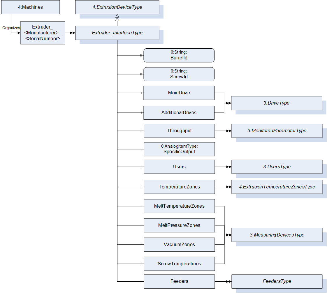
| Attribute | Value | ||||
| BrowseName | Extruder_InterfaceType | ||||
| IsAbstract | False | ||||
| References | Node Class | BrowseName | DataType | TypeDefinition | Other |
|---|---|---|---|---|---|
| Subtype of 4:ExtrusionDeviceType (defined in OPC 40084-1) | |||||
| 0:HasProperty | Variable | BarrelId | 0:String | 0:PropertyType | O, RO |
| 0:HasProperty | Variable | ScrewId | 0:String | 0:PropertyType | O, RO |
| 0:HasComponent | Object | MainDrive | 3:DriveType | O | |
| 0:HasComponent | Object | AdditionalDrives | 3:DrivesType | O | |
| 0:HasComponent | Object | Throughput | 3:MonitoredParameterType | O | |
| 0:HasComponent | Variable | SpecificOutput | 0:Double | 0:AnalogUnitType | O, RO |
| 0:HasComponent | Object | Users | 3:UsersType | M | |
| 0:HasComponent | Object | TemperatureZones | 4:ExtrusionTemperatureZonesType | M | |
| 0:HasComponent | Object | MeltTemperatureZones | 3:MeasuringDevicesType | O | |
| 0:HasComponent | Object | MeltPressureZones | 3:MeasuringDevicesType | O | |
| 0:HasComponent | Object | VacuumZones | 3:MeasuringDevicesType | O | |
| 0:HasComponent | Object | ScrewTemperatures | 4:ExtrusionTemperatureZonesType | O | |
| 0:HasComponent | Object | Feeders | FeedersType | O | |
| Conformance Units | |||||
|---|---|---|---|---|---|
| OPC 40084-3 Basic |
The BrowseName of the object instance shall be "Extruder_<Manufacturer>_<SerialNumber>"
Example: "Extruder_Coperion_0123456".
6.2 DeviceClass
The DeviceClass Property in the Identification Object inside the ExtrusionDeviceType shall have the value "Extruder".
6.3 LineId
This Property indicates to which extrusion line the extruder belongs to (e.g. "blown film line 2")
6.4 MachineConfiguration
The MachineConfigurationType is defined in OPC 40083 and provides information on the current configuration of a machine/device.
6.5 BarrelId
This Property indicates the Id of the barrel.
6.6 ScrewId
This Property indicates the Id of the screw.
6.7 MainDrive, AdditionalDrives
These object give information about the main drive and additional drives of the extruder. The DrivesType and DriveType are defined in OPC 40083.
6.8 Throughput
Throughput of the extruder in mass per time (e.g. kg/h).
6.9 SpecificOutput
Specific output of the extruder in mass per revolution.
6.10 Users
The UsersType is defined in OPC 40083 and provides information on the current users on the machine/device.
7 Container objects for the components of an extruder
Several components can occur several times in an extruder (e.g. temperature zones, feeders, screws). For these the following container objects are defined (see container concept in OPC 40083):
TemperatureZones
MeltTemperatureZones
MeltPressureZones
VacuumZones
ScrewTemperatures
AdditionalMeasuringDevices
Feeders
7.1 TemperatureZones
This ObjectType is a container for the temperature zones on the extruder barrel. The ExtrusionTemperatureZonesType is defined in OPC 40084-1.
7.2 MeltTemperatureZones
This Object is a container for the melt temperature zones. The zones are modelled as MeasuringDeviceType as defined in OPC 40083.
When instances for melt temperature zones are created, the BrowseNames shall be "MeltTemperatureZone_<Nr>" where <Nr> is a three-digit number with leading zeros, starting with "001".
The temperature of the melt shall be delivered in °C or F.
7.3 MeltPressureZones
This Object is a container for the melt pressure zones. The zones are modelled as MeasuringDeviceType as defined in OPC 40083.
When instances for melt pressure zones are created, the BrowseNames shall be "MeltPressureZone_<Nr>" where <Nr> is a three-digit number with leading zeros, starting with "001".
The pressure of the melt shall be delivered in bar or lbf/in² (=psi).
7.4 VacuumZones
This Object is a container for the vacuum zones. The zones are modelled as MeasuringDeviceType as defined in OPC 40083.
When instances for vacuum zones are created, the BrowseNames shall be "VacuumZone_<Nr>" where <Nr> is a three-digit number with leading zeros, starting with "001".
The pressure (absolute based on 0) shall be delivered in bar or lbf/in² (=psi).
7.5 ScrewTemperatures
This Object is a container for screw temperatures. The temperatures are modelled as ExtrusionTemperatureZonesType as defined in OPC 40084-1.
When instances for screw temperatures are created, the BrowseNames shall be "ScrewTemperature_<Nr>" where <Nr> is a three-digit number with leading zeros, starting with "001".
The temperature of the screw shall be delivered in °C of F.
7.6 FeedersType
This ObjectType is a container for the feeders. It is formally defined in Table 2.
| Attribute | Value | ||||
| BrowseName | FeedersType | ||||
| IsAbstract | False | ||||
| References | Node Class | BrowseName | DataType | TypeDefinition | Other |
|---|---|---|---|---|---|
| Subtype of 0:BaseObjectType defined in OPC 10000-5 | |||||
| 0:HasProperty | Variable | 0:NodeVersion | 0:String | 0:PropertyType | M, RO |
| 0:HasComponent | Object | Feeder_<Nr> | FeederType | OP | |
| 0:GeneratesEvent | ObjectType | 0:GeneralModelChangeEventType | |||
When instances for feeders and/or dosing units are created, the BrowseNames shall be "Feeder_<Nr>" where <Nr> is a three-digit number with leading zeros, starting with "001". The FeederType is defined in Table 3.
7.7 FeederType
The FeederType represents a device that transports material in an uncontrolled or controlled way. In the second case, the Feeder acts as a dosing unit. A feeder transports the material to a defined destination. This can be directly a barrel zone, but also another feeder which collects materials from several feeders above.
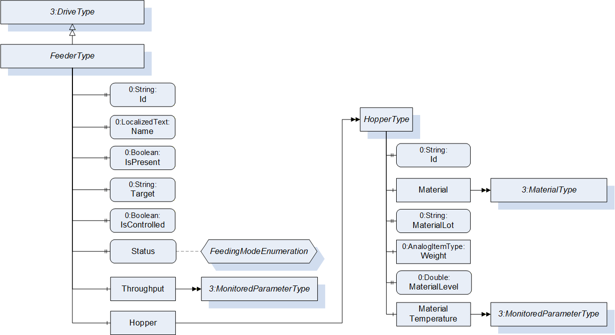
| Attribute | Value | ||||
| BrowseName | FeederType | ||||
| IsAbstract | False | ||||
| References | Node Class | BrowseName | DataType | TypeDefinition | Other |
|---|---|---|---|---|---|
| Subtype of 3:DriveType defined in OPC 40083 | |||||
| 0:HasProperty | Variable | Id | 0:String | 0:PropertyType | M, RO |
| 0:HasProperty | Variable | Name | 0:LocalizedText | 0:PropertyType | M, RO |
| 0:HasProperty | Variable | IsPresent | 0:Boolean | 0:PropertyType | M, RO |
| 0:HasProperty | Variable | Target | 0:String | 0:PropertyType | M, RO |
| 0:HasProperty | Variable | IsControlled | 0:Boolean | 0:PropertyType | O, RO |
| 0:HasProperty | Variable | Mode | FeedingModeEnumeration | 0:PropertyType | M, RO |
| 0:HasComponent | Object | Throughput | 3:MonitoredParameterType | O, RO | |
| 0:HasComponent | Object | Hopper | HopperType | O | |
7.7.1 Name
The Name Property gives the name of the feeder/dosing unit and is used as reference in the Target. Unique within the extruder
7.7.2 Description
The Description Property gives a description of the feeder/dosing unit.
7.7.3 IsPresent
The IsPresent Property provides information if the feeder/dosing unit is physically installed and connected.
7.7.4 IsActive
The IsActive Property provides information if the fedder/dosing unit is active in the current production.
7.7.5 Target
The Target Property provides information to where the feeder brings the material. This can be a barrel zone (ExtrusionTemperatureZone) but also another feeder. The value of the Target Property shall be equal to the value of the Id Property of the relevant ExtrusionTemperatureZone or feeder.
7.7.6 IsControlled
The IsControlled Property provides information, if the feeder is controlled (by a valve, screw, …) or not (material just falls through by gravity).
7.7.7 Mode
The Mode Property provides information, how the throughput of the feeder is controlled.
| Name | Value | Description |
| ONLY_CONVEYING | 0 | The throughput is not controlled. The feeder only transports the material (e.g. by screw, conveyor belt) or the material is only falling through a feed opening |
| OTHER | 1 | Throughput is controlled, but in another mode than these below |
| GRAVIMETRIC | 2 | The throughput is controlled by a gravimetric dosing system. |
| VOLUMETRIC | 3 | The throughput is controlled by a volumetric dosing system. |
| LIQUID | 4 | The throughput of liquid material is controlled by a pump. |
| BATCH | 5 | The throughput is controlled by a batch dosing system. Note In this case, each material has an own feeder although there is only one physical system. |
7.7.8 Throughput
Current throughput of the feeder/dosing unit in mass per time (e.g. kg/h). Although the modelling rule for this node is optional to cover also pure feeders, it is mandatory for dosing units. The MonitoredParameterType is defined in OPC 40083.
7.8 HopperType
The HopperType represent a device where material is brought into the extrusion process.
| Attribute | Value | ||||
| BrowseName | HopperType | ||||
| IsAbstract | False | ||||
| References | Node Class | BrowseName | DataType | TypeDefinition | Other |
|---|---|---|---|---|---|
| Subtype of 0:BaseObjectType defined in OPC 10000-5 | |||||
| 0:HasProperty | Variable | Id | 0:String | 0:PropertyType | M, RO |
| 0:HasComponent | Object | Material | 3:MaterialType | M | |
| 0:HasProperty | Variable | MaterialLot | 0:String | 0:PropertyType | O, RO |
| 0:HasComponent | Variable | Weight | 0:Double | 0:AnalogUnitType | O, RO |
| 0:HasComponent | Variable | MaterialLevel | 0:Double | 0:BaseDataVariableType | O, RO |
| 0:HasComponent | Object | MaterialTemperature | 3:MonitoredParameterType | O | |
7.8.1 IsActive
The IsActive property provides information if the hopper is refilled during the production so that the material is available for the production.
7.8.2 Material
The Material property gives information on the current material in the hopper. The MaterialType is defined in OPC 40083.
7.8.3 MaterialLot
Lot of the material that is recently filled in the hopper.
7.8.4 Weight
Actual weight of the material in the hopper (e.g. in kg).
7.8.5 MaterialLevel
Actual level of the material in the hopper unit in %.
7.8.6 MaterialTemperature
Actual temperature of the material inside the feeder in °C or °F. The MonitoredParameterType is defined in OPC 40083.
8 Profiles and Conformance Units
8.1 Conformance Units
This chapter defines the corresponding Conformance Unit for OPC 40084-3.
| Category | Title | Description |
| Server | OPC 40084-3 Basic | Support of Extruder_InterfaceType and all mandatory child elements giving information on the extruder and its status. There is at least one instance of the Extruder_InterfaceType in the Machines Object. |
8.2 Profiles
8.2.1 Profile list
Table 7 lists the Profile defined in this document and defines its URI.
| Profile | URI |
| OPC 40084-3 v2 Basic Server Profile | http://opcfoundation.org/UA-Profile/PlasticsRubber/Extrusion_v2/Extruder/Server/Basic |
8.2.2 Server Facets
This version of OPC 40084-3 defined only one Profile.
| Group | Conformance Unit / Profile Title | Mandatory / Optional |
| Extrusion | 4:Extrusion v2 Extrusion Device Basic Server Profile | M |
| Extrusion | OPC 40084-3 Basic | M |
9 Namespaces
9.1 Namespace Metadata
Table 9 defines the namespace metadata for this specification. The Object is used to provide version information for the namespace and an indication about static Nodes. Static Nodes are identical for all Attributes in all Servers, including the Value Attribute. See Part 5 for more details.
The information is provided as Object of type NamespaceMetadataType. This Object is a component of the Namespaces Object that is part of the Server Object. The NamespaceMetadataType ObjectType and its Properties are defined in Part 5.
The version information is also provided as part of the ModelTableEntry in the UANodeSet XML file. The UANodeSet XML schema is defined in Part 6.
| Attribute | Value | |||
| BrowseName | http://opcfoundation.org/UA/PlasticsRubber/Extrusion_v2/Extruder/ | |||
| Property | DataType | Value | ||
| NamespaceUri | String | http://opcfoundation.org/UA/PlasticsRubber/Extrusion_v2/Extruder/ | ||
| NamespaceVersion | String | 2.00 | ||
| NamespacePublicationDate | DateTime | 2022-05-01 | ||
| IsNamespaceSubset | Boolean | False | ||
| StaticNodeIdTypes | IdType[] | 0 | ||
| StaticNumericNodeIdRange | NumericRange[] | |||
| StaticStringNodeIdPattern | String | |||
9.2 Handling of OPC UA Namespaces
Namespaces are used by OPC UA to create unique identifiers across different naming authorities. The Attributes NodeId and BrowseName are identifiers. A Node in the UA AddressSpace is unambiguously identified using a NodeId. Unlike NodeIds, the BrowseName cannot be used to unambiguously identify a Node. Different Nodes may have the same BrowseName. They are used to build a browse path between two Nodes or to define a standard Property.
Servers may often choose to use the same namespace for the NodeId and the BrowseName. However, if they want to provide a standard Property, its BrowseName shall have the namespace of the standards body although the namespace of the NodeId reflects something else, for example the EngineeringUnits Property. All NodeIds of Nodes not defined in this document shall not use the standard namespaces.
Table 10 provides a list of mandatory and optional namespaces used in an OPC 40084-3 OPC UA Server.
| NamespaceURI | Description | Use |
| http://opcfoundation.org/UA/ | Namespace for NodeIds and BrowseNames defined in the OPC UA specification. This namespace shall have namespace index 0. | Mandatory |
| Local Server URI | Namespace for nodes defined in the local server. This may include types and instances used in a device represented by the server. This namespace shall have namespace index 1. | Mandatory |
| http://opcfoundation.org/UA/DI/ | Namespace for NodeIds and BrowseNames defined in OPC 10000-100. The namespace index is server specific. | Mandatory |
http://opcfoundation.org/UA/PlasticsRubber/ GeneralTypes/ | Namespace for NodeIds and BrowseNames defined in OPC 40083. The namespace index is server specific. | Mandatory |
http://opcfoundation.org/UA/PlasticsRubber/ Extrusion_v2/GeneralTypes/ | Namespace for NodeIds and BrowseNames defined in OPC 40084-1. The namespace index is server specific. | Mandatory |
| http://opcfoundation.org/UA/Machinery/ | Namespace for NodeIds and BrowseNames defined in OPC 40001-1. The namespace index is server specific. | Mandatory |
http://opcfoundation.org/UA/PlasticsRubber/ Extrusion_v2/Extruder/ | Namespace for NodeIds and BrowseNames defined in this specification. The namespace index is server specific. | Mandatory |
| Vendor specific types and instances | A server may provide vendor specific types like types derived from MachineType or MachineStatusType or vendor specific instances of devices in a vendor specific namespace. | Optional |
Table 11 provides a list of namespaces and their index used for BrowseNames in this specification. The default namespace of this specification is not listed since all BrowseNames without prefix use this default namespace.
| NamespaceURI | Namespace Index | Example |
| http://opcfoundation.org/UA/ | 0 | 0:NodeVersion |
| http://opcfoundation.org/UA/DI/ | 2 | 2:DeviceClass |
| http://opcfoundation.org/UA/PlasticsRubber/GeneralTypes/ | 3 | 3:MachineInformationType |
| http://opcfoundation.org/UA/PlasticsRubber/Extrusion_v2/GeneralTypes/ | 4 | 4:ExtrusionDeviceType |
| http://opcfoundation.org/UA/Machinery/ | 5 | 5:Machines |
Annex A OPC 40084-3 Namespace and mappings (Normative)
A.1 Namespace and identifiers for OPC 40084-3 Information Model
This appendix defines the numeric identifiers for all of the numeric NodeIds defined in this specification. The identifiers are specified in a CSV file with the following syntax:
<SymbolName>, <Identifier>, <NodeClass>Where the SymbolName is either the BrowseName of a Type Node or the BrowsePath for an Instance Node that appears in the specification and the Identifier is the numeric value for the NodeId.
The BrowsePath for an Instance Node is constructed by appending the BrowseName of the instance Node to the BrowseName for the containing instance or type. An underscore character is used to separate each BrowseName in the path. Let's take for example, the MachineInformationType ObjectType Node which has the ControllerName Property. The Name for the ControllerName InstanceDeclaration within the MachineInformationType declaration is: MachineInformationType_ControllerName.
The NamespaceUri for all NodeIds defined here is http://opcfoundation.org/UA/PlasticsRubber/Extrusion_v2/Extruder/
The CSV released with this version of the specification can be found here:
http://www.opcfoundation.org/UA/schemas/PlasticsRubber/Extrusion_v2/Extruder/2.00/NodeIds.csv
http://www.opcfoundation.org/UA/schemas/PlasticsRubber/Extrusion_v2/Extruder/NodeIds.csv
A computer processible version of the complete Information Model defined in this specification is also provided. It follows the XML Information Model schema syntax defined in Part 6.
The Information Model Schema released with this version of the specification can be found here:
___________
Agreement of Use
COPYRIGHT RESTRICTIONS
This document is provided "as is" by the OPC Foundation and EUROMAP.
Right of use for this specification is restricted to this specification and does not grant rights of use for referred documents.
Right of use for this specification will be granted without cost.
This document may be distributed through computer systems, printed or copied as long as the content remains unchanged and the document is not modified.
OPC Foundation and EUROMAP do not guarantee usability for any purpose and shall not be made liable for any case using the content of this document.
The user of the document agrees to indemnify OPC Foundation and EUROMAP and their officers, directors and agents harmless from all demands, claims, actions, losses, damages (including damages from personal injuries), costs and expenses (including attorneys' fees) which are in any way related to activities associated with its use of content from this specification.
The document shall not be used in conjunction with company advertising, shall not be sold or licensed to any party.
The intellectual property and copyright is solely owned by the OPC Foundation and EUROMAP.
PATENTS
The attention of adopters is directed to the possibility that compliance with or adoption of OPC or EUROMAP specifications may require use of an invention covered by patent rights. OPC Foundation or EUROMAP shall not be responsible for identifying patents for which a license may be required by any OPC or EUROMAP specification, or for conducting legal inquiries into the legal validity or scope of those patents that are brought to its attention. OPC or EUROMAP specifications are prospective and advisory only. Prospective users are responsible for protecting themselves against liability for infringement of patents.
WARRANTY AND LIABILITY DISCLAIMERS
WHILE THIS PUBLICATION IS BELIEVED TO BE ACCURATE, IT IS PROVIDED "AS IS" AND MAY CONTAIN ERRORS OR MISPRINTS. THE OPC FOUDATION NOR EUROMAP MAKES NO WARRANTY OF ANY KIND, EXPRESSED OR IMPLIED, WITH REGARD TO THIS PUBLICATION, INCLUDING BUT NOT LIMITED TO ANY WARRANTY OF TITLE OR OWNERSHIP, IMPLIED WARRANTY OF MERCHANTABILITY OR WARRANTY OF FITNESS FOR A PARTICULAR PURPOSE OR USE. IN NO EVENT SHALL THE OPC FOUNDATION NOR EUROMAP BE LIABLE FOR ERRORS CONTAINED HEREIN OR FOR DIRECT, INDIRECT, INCIDENTAL, SPECIAL, CONSEQUENTIAL, RELIANCE OR COVER DAMAGES, INCLUDING LOSS OF PROFITS, REVENUE, DATA OR USE, INCURRED BY ANY USER OR ANY THIRD PARTY IN CONNECTION WITH THE FURNISHING, PERFORMANCE, OR USE OF THIS MATERIAL, EVEN IF ADVISED OF THE POSSIBILITY OF SUCH DAMAGES.
The entire risk as to the quality and performance of software developed using this specification is borne by you.
RESTRICTED RIGHTS LEGEND
This Specification is provided with Restricted Rights. Use, duplication or disclosure by the U.S. government is subject to restrictions as set forth in (a) this Agreement pursuant to DFARs 227.7202-3(a); (b) subparagraph (c)(1)(i) of the Rights in Technical Data and Computer Software clause at DFARs 252.227-7013; or (c) the Commercial Computer Software Restricted Rights clause at FAR 52.227-19 subdivision (c)(1) and (2), as applicable. Contractor / manufacturer are the OPC Foundation, 16101 N. 82nd Street, Suite 3B, Scottsdale, AZ, 85260-1830
COMPLIANCE
The combination of EUROMAP and OPC Foundation shall at all times be the sole entities that may authorize developers, suppliers and sellers of hardware and software to use certification marks, trademarks or other special designations to indicate compliance with these materials as specified within this document. Products developed using this specification may claim compliance or conformance with this specification if and only if the software satisfactorily meets the certification requirements set by EUROMAP or the OPC Foundation. Products that do not meet these requirements may claim only that the product was based on this specification and must not claim compliance or conformance with this specification.
TRADEMARKS
Most computer and software brand names have trademarks or registered trademarks. The individual trademarks have not been listed here.
GENERAL PROVISIONS
Should any provision of this Agreement be held to be void, invalid, unenforceable or illegal by a court, the validity and enforceability of the other provisions shall not be affected thereby.
This Agreement shall be governed by and construed under the laws of Germany.
This Agreement embodies the entire understanding between the parties with respect to, and supersedes any prior understanding or agreement (oral or written) relating to, this specification.