
6 OPC UA FX ObjectTypes
6.1 OPC UA FX ObjectTypes overview
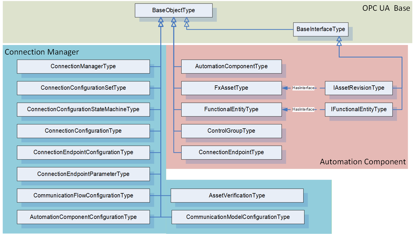
This document defines several ObjectTypes that can be used to create an OPC UA FX Information Model. It also specifies a number of Interfaces that can be applied to existing Information Models, allowing existing models to be used as part of an OPC UA FX system. For additional guidance on mapping this model to existing Information Models, see Annex B. For an overview of the main OPC UA FX ObjectTypes, see Figure 17.
Since the OPC UA FX Information Model supports small embedded devices as well as powerful controllers, it includes many optional items. Some of these items are mandatory for controller-level Profiles but optional for embedded device Profiles. For a complete list of Profiles related to OPC UA FX, see OPC 10000-84.
6.2 AutomationComponentType
6.2.1 Overview
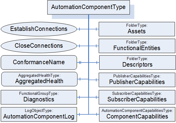
The AutomationComponentType ObjectType provides for a grouping of Assets and FunctionalEntities in a given model. It exposes a Method that is used to establish Connections between FunctionalEntities. An overview of the AutomationComponentType is illustrated in Figure 18.
6.2.2 AutomationComponentType definition
The AutomationComponentType is the base ObjectType for an OPC UA FX device, controller, PLC, instrument, etc. It includes information related to the current Asset, the available functionality, its capabilities (including communication-related capabilities) and any related offline information. The AutomationComponentType is formally defined in Table 4 and Table 5.
| Attribute | Value | ||||
| BrowseName | 3:AutomationComponentType | ||||
| IsAbstract | False | ||||
| References |
Node
Class | BrowseName | DataType | TypeDefinition | Other |
|---|---|---|---|---|---|
| Subtype of the 0:BaseObjectType defined in OPC 10000-5 | |||||
| 0:HasComponent | Object | 3:FunctionalEntities | 0:FolderType | M | |
| 0:HasComponent | Object | 3:Assets | 0:FolderType | M | |
| 0:HasComponent | Object | 3:PublisherCapabilities | 3:PublisherCapabilitiesType | O | |
| 0:HasComponent | Object | 3:SubscriberCapabilities | 3:SubscriberCapabilitiesType | O | |
| 0:HasComponent | Object | 3:ComponentCapabilities | 3:AutomationComponentCapabilitiesType | M | |
| 0:HasProperty | Variable | 3:ConformanceName | 0:UriString | 0:PropertyType | O |
| 0:HasComponent | Method | 3:EstablishConnections | Defined in 6.2.4 | M | |
| 0:HasComponent | Method | 3:CloseConnections | Defined in 6.2.5 | M | |
| 0:HasComponent | Object | 3:Descriptors | 0:FolderType | M | |
| 0:HasComponent | Variable | 3:AggregatedHealth | 3:AggregatedHealthDataType | 3:AggregatedHealthType | M |
| 0:HasComponent | Object | 5:Diagnostics | 5:FunctionalGroupType | O | |
| 0:HasComponent | Object | 3:AutomationComponentLog | 0:LogObjectType | O | |
| 0:GeneratesEvent | ObjectType | 0:SystemStatusChangeEventType | Defined in OPC 10000-3 | ||
| ConformanceUnits | |||||
|---|---|---|---|---|---|
| UAFX AutomationComponent Base |
| SourceBrowsePath | Reference Type | IsForward | TargetBrowsePath | ||||
| 0:IsHostedBy | True |
|
The components of the AutomationComponentType have additional subcomponents, which are defined in Table 6.
| BrowsePath | References | NodeClass | BrowseName | DataType | TypeDefinition | Others |
| 3:FunctionalEntities | 0:Organizes | Object | 3:<FunctionalEntity> | 3:FunctionalEntityType | OP | |
| 3:Assets | 0:Organizes | Object | 3:<Asset> | 3:FxAssetType | OP | |
| 5:Diagnostics | 0:HasComponent | Variable | 3:EstablishCallCount | 0:UInt32 | 0:BaseDataVariableType | O |
| 5:Diagnostics | 0:HasComponent | Variable | 3:EstablishCallFailedCount | 0:UInt32 | 0:BaseDataVariableType | O |
| 5:Diagnostics | 0:HasComponent | Variable | 3:CloseCallCount | 0:UInt32 | 0:BaseDataVariableType | O |
| 5:Diagnostics | 0:HasComponent | Variable | 3:CloseCallFailedCount | 0:UInt32 | 0:BaseDataVariableType | O |
FunctionalEntities provides a Folder for the FunctionalEntities that this AutomationComponent exposes. The Folder shall be restricted to hold only instances of a type derived from FunctionalEntityType or instances that implement the IFunctionalEntityType Interface. The Folder may be empty. FunctionalEntities can reference other FunctionalEntities, but FunctionalEntities that are directly referenced from this Folder are considered top-level FunctionalEntities.
Assets provides a Folder for assets. It shall include all assets that are referenced from the FunctionalEntities of this AutomationComponent. An Asset might be a complex type that includes other Assets. Assets directly referenced from this Folder are considered top-level Assets. For more details on the asset model, see 6.3. The Folder shall be restricted to hold only instances of FxAssetType or a subtype of it, or instances that implement the IVendorNameplateType, ITagNameplateType, and IAssetRevisionType Interfaces. The Folder may be empty; however, typically, there is at least one entry in this Folder. For examples of Assets, see Annex D.
Objects may be added/removed to/from the FunctionalEntities or Assets Folders during operation, in which case the Server shall generate GeneralModelChangeEvent to reflect these changes.
The optional PublisherCapabilities provide the Publisher capabilities associated with this AutomationComponent. They apply to all instances in the FunctionalEntities Folder. An individual FunctionalEntity can further restrict these capabilities. If an AutomationComponent supports being a Publisher as defined in OPC 10000-14, then an instance of this Object shall be provided.
The optional SubscriberCapabilities provides the general Subscriber capabilities associated with this AutomationComponent. They apply to all instances in the FunctionalEntities Folder. An individual FunctionalEntity can further limit these capabilities. If an AutomationComponent supports being a Subscriber as defined in OPC 10000-14, then an instance of this Object shall be provided.
ComponentCapabilities is an AutomationComponentCapabilitiesType Folder that describes the functionality provided by an AutomationComponent (e.g., number of supported Connections, etc.).
The optional ConformanceName provides the URL to the product’s listing on the OPC Foundation website, under which the result of the conformance testing for this product can be found. The product's name may be different from the name of the AutomationComponent since conformance testing may be done for a product family, but this shall be described on the OPC Foundation product page. The DisplayName of the instance of the AutomationComponent shall be able to be resolved on the Website to the specifics of the product that was tested. Furthermore, at least one Asset listed in this AutomationComponent shall include IVendorNameplateType information on the related OPC Foundation product page.
Descriptors is a Folder that can contain AcDescriptors. Typically, at least one AcDescriptor is included, but depending on the system's architecture, additional AcDescriptors might be added. These added AcDescriptors describe added FunctionalEntities or added Assets or added combinations of Assets and FunctionalEntities. The additions can result from application developers adding functionality, integration of this AutomationComponent into a larger piece of Equipment, or the addition of modular Assets to the system. This Folder may also contain other Folders that can be used to organise the AcDescriptors.
AggregatedHealth provides the aggregated health of the AutomationComponent; this includes an aggregation of the health of all included Assets and FunctionalEntities. For the definition of the AggregatedHealthType and the aggregation rules, see 9.1.
AutomationComponentLog exposes a LogObject for the AutomationComponent. The LogObject (see OPC 10000-26) can be accessed to obtain the log of activity related to this AutomationComponent. Events can be mapped to LogRecords (see OPC 10000-26) for the LogObject. LogObject records can also be generated without the generation of an Event. If the LogObject is supported, the AutomationComponent shall produce LogRecords for all calls of the EstablishConnections and CloseConnections Methods. The LogObject configuration would determine if the LogRecords are stored. The LogRecords shall include the optional TraceContext information if it is provided by the client invoking the EstablishConnection or CloseConnection calls. In addition, it is recommended that for errors, the AdditionalData field includes the error information as described in the OPC 10000-26 Log Event EventType clause.
Diagnostics is a FunctionalGroup (Folder) that contains Variables that report diagnostic statistics and counters (see OPC 10000-100 Recommended FunctionalGroup BrowseNames).
EstablishCallCount diagnostics counter Variable provides a count of the number of EstablishConnections calls received.
EstablishCallFailedCount diagnostics counter Variable provides a count of the number of EstablishConnections calls that failed (any command).
CloseCallCount diagnostics counter Variable provides a count of the number of CloseConnections calls received.
CloseCallFailedCount diagnostics counter Variable provides a count of the number of CloseConnections calls that failed.
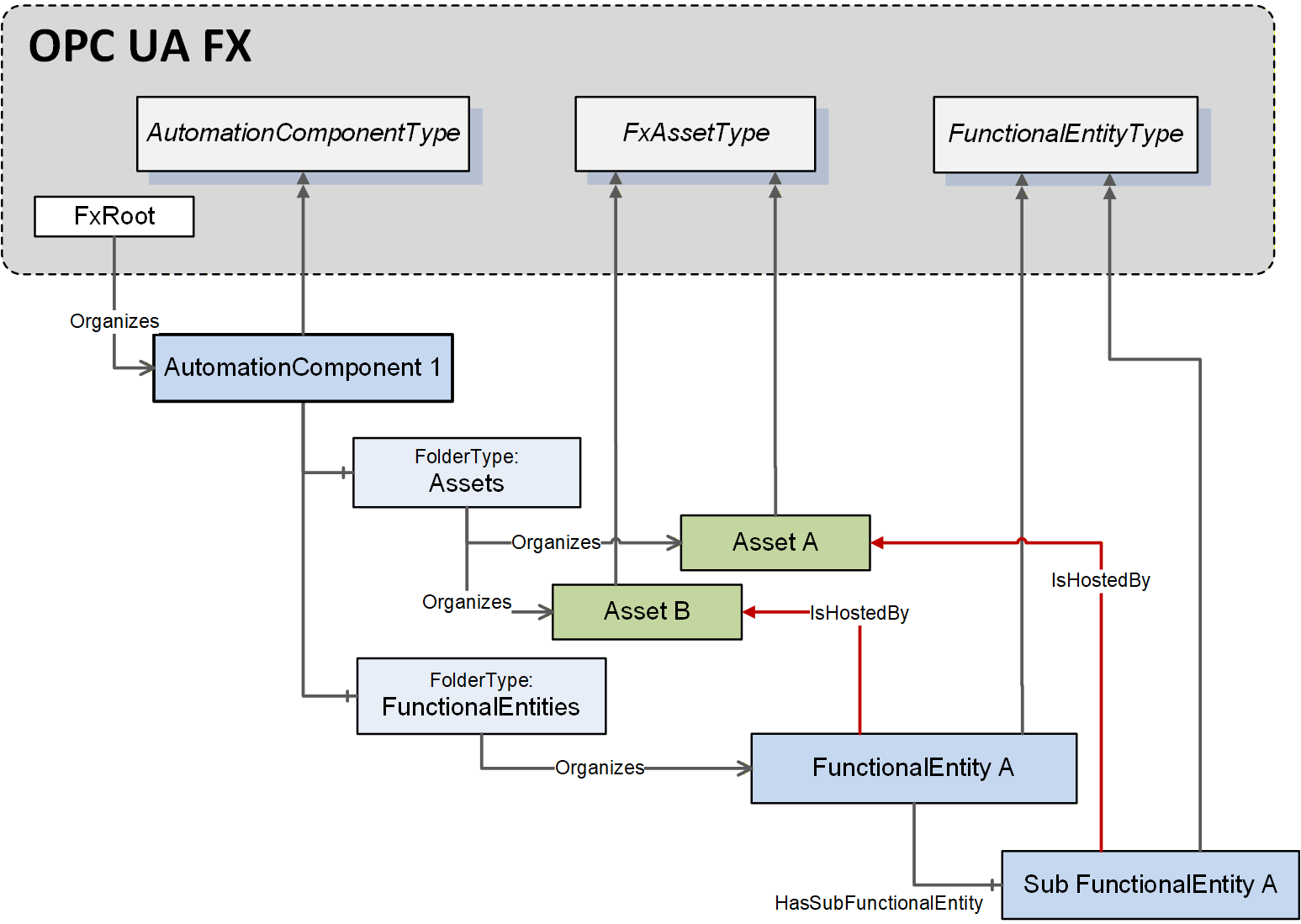
The IsHostedBy ReferenceType (see OPC 10000-23) indicates the Assets used to execute the functionality provided by a FunctionalEntity. There may be multiple IsHostedBy References from one FunctionalEntity to multiple Assets. An example is a drive axis FunctionalEntity, which has IsHostedBy References to a drive inverter Asset and a motor Asset. Another example is an input FunctionalEntity having IsHostedBy References to the input module, the head, and the firmware Assets of a modular device.
Figure 19 illustrates an example of the usage of IsHostedBy.
If Eventing is supported, the AutomationComponent shall generate Events of SystemStatusChangeEventType (see OPC 10000-3) if the ServerState changes (e.g., following a power cycle).
6.2.3 AcDescriptorType definition
An instance of AcDescriptorType is used to represent a Descriptor. This Object shall include either a DescriptorFile or the pair of DescriptorIdentifier and DescriptorVersion. It may include all three.
The AcDescriptorType is formally defined in Table 7.
| Attribute | Value | ||||
| BrowseName | 3:AcDescriptorType | ||||
| IsAbstract | False | ||||
| References | Node Class | BrowseName | DataType | TypeDefinition | Other |
|---|---|---|---|---|---|
| Subtype of the 0:BaseObjectType defined in OPC 10000-5 | |||||
| 0:HasProperty | Variable | 3:DescriptorIdentifier | 0:UriString | 0:PropertyType | O |
| 0:HasProperty | Variable | 3:DescriptorVersion | 3:FxVersion | 0:PropertyType | O |
| 0:HasComponent | Object | 3:DescriptorFile | 0:FileType | O | |
| ConformanceUnits | |||||
|---|---|---|---|---|---|
| UAFX AutomationComponent Descriptor |
The optional DescriptorIdentifier provides a globally unique identifier of the Descriptor of the AutomationComponent. It can be used to retrieve the Descriptor from the vendor’s product listing on the OPC Foundation Website (i.e., the OPC Marketplace).
The optional DescriptorVersion provides the version of the Descriptor used to describe this AutomationComponent.
The optional DescriptorFile exposes the Descriptor (defined in OPC 10000-83) directly from the AutomationComponent.
If both the DescriptorFile and the DescriptorIdentifier are provided, the value of the DescriptorIdentifier Variable exposed in the Object shall match the value of DescriptorIdentifier provided in the manifest of the DescriptorFile. If, in addition, the DescriptorVersion is provided, the value of the DescriptorVersion Variable exposed in the Object shall match the value of DescriptorVersion provided in the manifest of the DescriptorFile.
6.2.4 EstablishConnections method
6.2.4.1 Overview
The EstablishConnections Method establishes one or more Connections. The ConnectionManager typically calls it. It allows for creating ConnectionEndpoints, establishing control, verifying FunctionalEntity and Asset compatibility, applying ConfigurationData, and configuring the communication model to be used for data exchange. It is recommended that this Method be restricted to Client connections that have the well-known Role ConnectionAdmin as defined in Clause 5.9.
6.2.4.2 EstablishConnections signature
The signature of this Method is specified below; the arguments are defined in Table 8.
Signature
	EstablishConnections (
	  [in] 2:FxCommandMask				CommandMask,
	  [in] 2:AssetVerificationDataType[]		AssetVerifications,
	  [in] 2:ConnectionEndpointConfigurationDataType[]
								ConnectionEndpointConfigurations,
	  [in] 2:ReserveCommunicationIdsDataType[]	ReserveCommunicationIds,
	  [in] 2:CommunicationConfigurationDataType[]	CommunicationConfigurations,

	  [out] 2:AssetVerificationResultDataType[]	AssetVerificationResults,
	  [out] 2:ConnectionEndpointConfigurationResultDataType[]
							ConnectionEndpointConfigurationResults,
	  [out] 2:ReserveCommunicationIdsResultDataType[]
								ReserveCommunicationIdsResults,
	  [out] 2:CommunicationConfigurationResultDataType[]
								CommunicationConfigurationResults
);| Argument | Description |
| CommandMask | CommandMask provides the commands to be processed by the implementation of this Method. How individual commands shall be processed is described in 6.2.4.3. The CommandMask contains bits for the following commands: VerifyAssetCmd (see 6.2.4.3.2), VerifyFunctionalEntityCmd (see 6.2.4.3.3 ), ReserveCommunicationIdsCmd (see 6.2.4.3.4), CreateConnectionEndpointCmd (see 6.2.4.3.5), EstablishControlCmd (see 6.2.4.3.6), SetConfigurationDataCmd (see 6.2.4.3.7), ReassignControlCmd (see 6.2.4.3.8), SetCommunicationConfigurationCmd (see 6.2.4.3.9), and EnableCommunicationCmd (see 6.2.4.3.10). For a formal definition of the CommandMask, see 10.23. The CommandMask shall have at least one command bit set to TRUE. |
| AssetVerifications | Provides parameters for Asset verification. For a formal definition of the AssetVerificationDataType, see 10.5. If CommandMask VerifyAssetCmd is set, AssetVerifications shall contain at least one element. If CommandMask VerifyAssetCmd is not set, AssetVerifications shall be null or empty. |
| ConnectionEndpointConfigurations | Provides configuration information for Connections. For a formal definition of the ConnectionEndpointConfigurationDataType, see 10.14. If CommandMask VerifyFunctionalEntityCmd, CreateConnectionEndpointCmd, EstablishControlCmd, SetConfigurationDataCmd, ReassignControlCmd, SetCommunicationConfigurationCmd, or EnableCommunicationCmd is set, ConnectionEndpointConfigurations shall contain at least one element. If CommandMask VerifyFunctionalEntityCmd, CreateConnectionEndpointCmd, EstablishControlCmd, SetConfigurationDataCmd, ReassignControlCmd, SetCommunicationConfigurationCmd, and EnableCommunicationCmd are not set, ConnectionEndpointConfigurations shall be null or empty. If CommandMask VerifyFunctionalEntityCmd is set, at least one of the ConnectionEndpointConfigurations elements shall contain ExpectedVerificationVariables with at least one element. If CommandMask VerifyFunctionalEntityCmd is not set, all ExpectedVerificationVariables in all ConnectionEndpointConfigurations shall be null or empty. For the EstablishControlCmd, SetConfigurationDataCmd, ReassignControlCmd, SetCommunicationConfigurationCmd, or EnableCommunicationCmd, a non-null ConnectionEndpoint is required. If CommandMask CreateConnectionEndpointCmd is set, at least one of the ConnectionEndpointConfigurations elements shall expose ConnectionEndpointDefinitionDataType with Parameter (see 10.16) as ConnectionEndpoint. If CommandMask CreateConnectionEndpointCmd is not set, all ConnectionEndpointConfigurations elements shall expose ConnectionEndpointDefinitionDataType with Node (see 10.16) as ConnectionEndpoint. If CommandMask EstablishControlCmd or ReassignControlCmd is set, at least one of the ConnectionEndpointConfigurations elements shall contain ControlGroups with at least one element. If CommandMask EstablishControlCmd and ReassignControlCmd are not set, all ControlGroups in all ConnectionEndpointConfigurations shall be null or empty. If CommandMask SetConfigurationDataCmd is set, at least one of the ConnectionEndpointConfigurations elements shall contain ConfigurationData with at least one element. If CommandMask SetConfigurationDataCmd is not set, all ConfigurationData in all ConnectionEndpointConfigurations shall be null or empty. If CommandMask SetCommunicationConfigurationCmd is set, at least one of the ConnectionEndpointConfigurations elements shall contain a non-null CommunicationLinks. If CommandMask SetCommunicationConfigurationCmd is not set, all CommunicationLinks in all ConnectionEndpointConfigurations shall be set to null. |
| ReserveCommunicationIds | Provides the request for communication model-specific identifiers. For a formal definition of the ReserveCommunicationIdsDataType, see 10.43. If CommandMask ReserveCommunicationIdsCmd is set, ReserveCommunicationIds shall contain at least one element. If CommandMask ReserveCommunicationIdsCmd is not set, ReserveCommunicationIds shall be null or empty. |
| CommunicationConfigurations | Provides the ConfigurationData specific to the communication model utilised by the provided Connections. For a formal definition of the CommunicationConfigurationDataType, see 10.10. If CommandMask SetCommunicationConfigurationCmd is set, CommunicationConfigurations shall contain a single element. If CommandMask SetCommunicationConfigurationCmd is not set, CommunicationConfigurations shall be null or empty. |
| AssetVerificationResults | Indicates the results for the command VerifyAssetCmd (see 6.2.4.3.2). For a formal definition of the AssetVerificationResultDataType, see 10.6. If CommandMask VerifyAssetCmd is set, the length of this array shall match the length of AssetVerifications, and each element shall contain the result of the corresponding element in AssetVerifications. If CommandMask VerifyAssetCmd is not set, it shall be null or empty. |
| ConnectionEndpointConfigurationResults | Indicates the results for the commands VerifyFunctionalEntityCmd (see 6.2.4.3.3), CreateConnectionEndpointCmd (see 6.2.4.3.5), EstablishControlCmd (see 6.2.4.3.6), SetConfigurationDataCmd (see 6.2.4.3.7), ReassignControlCmd (see 6.2.4.3.8), SetCommunicationConfigurationCmd (see 6.2.4.3.9) or EnableCommunicationCmd (see 6.2.4.3.10). For a formal definition of the ConnectionEndpointConfigurationResultDataType, see 10.15. If CommandMask VerifyFunctionalEntityCmd, CreateConnectionEndpointCmd, EstablishControlCmd, SetConfigurationDataCmd, ReassignControlCmd, SetCommunicationConfigurationCmd, or EnableCommunicationCmd are set, the length of this array shall match the length of ConnectionEndpointConfigurations, and each element shall contain the result of the corresponding element in ConnectionEndpointConfigurations. If CommandMask VerifyFunctionalEntityCmd, CreateConnectionEndpointCmd, EstablishControlCmd, SetConfigurationDataCmd, ReassignControlCmd, SetCommunicationConfigurationCmd, and EnableCommunicationCmd are not set, it shall be null or empty. For the setting of the individual results in the ConnectionEndpointConfigurationResultDataType, see 6.2.4.3 (if the appropriate CommandMask bit is set) and 10.15 (if the appropriate CommandMask bit is not set). |
| ReserveCommunicationIdsResults | Indicates the results for the command ReserveCommunicationIdsCmd (see 6.2.4.3.4). For a formal definition of the ReserveCommunicationIdsResultDataType, see 10.44. If CommandMask ReserveCommunicationIdsCmd is set, the length of this array shall match the length of the ReserveCommunicationIds, and each element shall contain the result of the corresponding element in ReserveCommunicationIds. If CommandMask ReserveCommunicationIdsCmd is not set, it shall be null or empty. |
| CommunicationConfigurationResults | Indicates the result for the command SetCommunicationConfigurationCmd (see 6.2.4.3.9). For a formal definition of the CommunicationConfigurationResultDataType, see 10.11. If CommandMask SetCommunicationConfigurationCmd is set, a single element shall exist containing the result of the SetCommunicationConfigurationCmd command. If CommandMask SetCommunicationConfigurationCmd is not set, it shall be null or empty. |
The possible Method result codes are formally defined in Table 9.
| Result Code | Description |
|---|---|
| Bad_InvalidArgument | One or multiple Arguments do not match the requirements specified for the commands set in CommandMask (see Table 8), or no bits in CommandMask are set. |
| Bad_InvalidState | A command bit or combination of command bits set in CommandMask cannot be processed in the AutomationComponent’s current state. |
| Bad_TooManyOperations | The requested number of Connections to establish exceeds the MaxConnectionsPerCall capability of the AutomationComponent (see 6.2.6). |
| Uncertain | The Method was aborted due to errors while executing a command. Depending on the executed commands, one or more of the AssetVerificationResults, ConnectionEndpointConfigurationResults, ReserveCommunicationIdsResults, and CommunicationConfigurationResults will contain additional information. |
The possible StatusCodes for the AssetVerificationResults VerificationStatus are formally defined in Table 10.
| Result Code | Description |
|---|---|
| Bad_NodeIdUnknown | AssetToVerify does not exist in the Server address space. |
| Bad_NodeIdInvalid | The syntax of AssetToVerify is invalid. |
| Bad_InvalidArgument | AssetToVerify is not an Asset. |
| Also, include all Result Codes in Table 32. |
The possible StatusCodes for the ConnectionEndpointConfigurationResults FunctionalEntityNodeResult are formally defined in Table 11.
| Result Code | Description |
|---|---|
| Bad_NodeIdUnknown | The NodeId for FunctionalEntityNode does not exist in the Server address space. |
| Bad_NodeIdInvalid | The syntax of the NodeId for FunctionalEntityNode was invalid. |
| Bad_InvalidArgument | The NodeId for FunctionalEntityNode was not a FunctionalEntity or related to the AutomationComponent on which EstablishConnections was called. |
| Good | The NodeId for FunctionalEntityNode was valid. |
The possible StatusCodes for the ConnectionEndpointConfigurationResults ConnectionEndpointResult are formally defined in Table 12.
| Result Code | Description |
| Bad_NotSupported | The requested IsPersistent was not supported. The requested Connection does not include a feedback signal (PubSubConnectionEndpointParameterDataType Mode is set to Publisher), but the FunctionalEntity requires it (FeedbackSignalRequired is set to TRUE (see 6.4.7)). |
| Bad_TypeDefinitionInvalid | The requested ConnectionEndpointTypeId does not reference a supported type (see 6.6). |
| Bad_InvalidArgument | Neither InputVariableIds nor OutputVariableIds was specified. An element of InputVariableIds or OutputVariableIds has an unknown or invalid NodeId or was not a Variable. An element of InputVariableIds is not referenced from an input folder in either the FunctionalEntityNode or a SubFunctionalEntity of it. An element of OutputVariableIds is not referenced from an output folder in either the FunctionalEntityNode or a SubFunctionalEntity of it. The NodeId for the requested ConnectionEndpoint was not a ConnectionEndpoint. A null RelatedEndpoint was specified. A null ConnectionEndpoint was supplied, but the command required a ConnectionEndpoint. The requested ConnectionEndpointTypeId does not match a concrete subtype of ConnectionEndpointType. A preconfigured ConnectionEndpoint exists, but it does not match the requested parameters. The preconfigured ConnectionEndpoint was not found. This error code may also be used for any other parameter error in an EstablishConnections Call. |
| Bad_BrowseNameDuplicated | The name for the ConnectionEndpoint was not unique within the scope of the FunctionalEntity’s ConnectionEndpoints Folder. |
| Bad_ResourceUnavailable | Maximum number of Connections exceeded. See AutomationComponentCapabilityType MaxConnections in section 6.2.6. An AutomationComponent may set this StatusCode, even if the optional AutomationComponentCapability MaxConnections does not exist. |
| Bad_NothingToDo | The operation was skipped. Creating this ConnectionEndpoint was skipped because a preceding command had already resulted in an error. |
| Bad_NodeIdUnknown | The NodeId for the requested ConnectionEndpoint does not exist in the FunctionalEntity. |
| Bad_NodeIdInvalid | The syntax of the NodeId for the requested ConnectionEndpoint was invalid. |
| Bad_RequestNotAllowed | The ConnectionEndpoint to be enabled references input Variables, which are referenced by another enabled ConnectionEndpoint. |
| Bad_InvalidState | A preconfigured ConnectionEndpoint exists, but it is currently in use, as indicated by a RelatedEndpoint. |
| Good | Creating or using the ConnectionEndpoint succeeded. |
The possible StatusCodes for the ConnectionEndpointConfigurationResults EstablishControlResult are formally defined in Table 13.
| Result Code | Description |
| Bad_NodeIdUnknown | The NodeId for the requested ControlGroup does not exist in the FunctionalEntity. |
| Bad_NodeIdInvalid | The syntax of the NodeId for the requested ControlGroup was invalid. |
| Bad_InvalidArgument | The NodeId for the requested ControlGroup was not a ControlGroup. |
| Bad_NothingToDo | Establishing control was skipped because a preceding command had already resulted in an error. |
| Also, include all Result Codes in Table 65. |
The possible StatusCodes for the ConnectionEndpointConfigurationResults ConfigurationDataResult are formally defined in Table 14.
| Result Code | Description |
| Bad_NodeIdUnknown | The NodeId for the requested Key does not exist in the FunctionalEntity hierarchy. |
| Bad_NodeIdInvalid | The syntax of the NodeId for the requested Key was invalid. |
| Bad_InvalidArgument | The NodeId for the requested Key was not a Node in the ConfigurationData Folder hierarchy. |
| Bad_TypeMismatch | The value supplied for the configuration Variable is not of the same type as the implemented configuration Variable. |
| Bad_UserAccessDenied | The change to a configuration Variable failed; this may result from a Lock existing on the Variable. |
| Bad_NothingToDo | Applying the Value to this Key was skipped because a preceding command had already resulted in an error. |
| Bad_ConfigurationError | The applied configuration data is inconsistent. |
| Good | Setting the ConfigurationData succeeded. |
The possible StatusCodes for the ConnectionEndpointConfigurationResults ReassignControlResult are formally defined in Table 15.
| Result Code | Description |
| Bad_NodeIdUnknown | The NodeId for the requested ControlGroup does not exist in the FunctionalEntity. |
| Bad_NodeIdInvalid | The syntax of the NodeId for the requested ControlGroup was invalid. |
| Bad_InvalidArgument | The NodeId for the requested ControlGroup was not a ControlGroup, or the LockContext was null, invalid, or non-existent. |
| Bad_NothingToDo | Reassigning control was skipped because a preceding command had already resulted in an error. |
| Bad_ConfigurationError | The applied configuration data is inconsistent. |
| Also, include all Result Codes in Table 70 |
The possible StatusCodes for the ConnectionEndpointConfigurationResults CommunicationLinksResult are formally defined in Table 16.
| Result Code | Description |
| Bad_NotFound | At least one of the configuration elements referenced by the CommunicationLinks was not found in the CommunicationConfiguration. |
| Bad_InvalidArgument | At least one of the CommunicationLinks contains an invalid ConfigurationMask (see Table 148). |
| Bad_NoMatch | At least one of the configuration elements referenced by the CommunicationLinks does not match the ConnectionEndpoint. |
| Bad_ConfigurationError | The version of the DataSet related to the DataSetReader and/or DataSetWriter referenced by the CommunicationLinks does not match the expected version. |
| Bad_NothingToDo | Establishing communication links was skipped because a preceding command had already resulted in an error. |
| Bad_InvalidState | At least one of the configuration elements referenced by the CommunicationLinks or one of its parent elements is not persisted for a persistent ConnectionEndpoint. |
| Good | The operation was either successfully executed or not executed since CommandMask SetCommunicationConfigurationCmd was not set. |
| Also, include all StatusCodes defined by OPC 10000-14 |
The possible StatusCodes for the ConnectionEndpointConfigurationResults EnableCommunicationResult are formally defined in Table 17.
| Result Code | Description |
| Bad_NothingToDo | EnableCommunicationCmd was skipped because a preceding command had already resulted in an error. |
| Bad_RequestNotAllowed | The ConnectionEndpoint to be enabled references InputVariables, which are referenced by another enabled ConnectionEndpoint. |
| Bad_InvalidState | Required ToDataSetReader or ToDataSetWriter References are not configured for the ConnectionEndpoint. |
| Good | The operation was either successfully executed or not executed since CommandMask EnableCommunicationCmd was not set. |
| Also, include all StatusCodes defined by OPC 10000-14 |
The possible StatusCodes for the ReserveCommunicationIdsResults Result are formally defined in Table 18.
| Result Code | Description |
| Include all Method Result Codes of the ReserveIds Method defined by OPC 10000-14 |
The possible StatusCodes for the CommunicationConfigurationResults Result are formally defined in Table 19.
| Result Code | Description |
| Bad_ConfigurationError | The communication configuration violates the capabilities of the AutomationComponent, FunctionalEntity, Input- or OutputGroup, or the applied configuration data is inconsistent. |
| Bad_ResourceUnavailable | The Server does not have enough resources to add the entire PubSub configuration. |
| Bad_InvalidState | The current State of the Object does not allow a configuration change. |
| Bad_NothingToDo | The ConfigurationReferences array is null or empty, or the SetCommunicationConfigurationCmd was skipped because a preceding command had already resulted in an error. |
The EstablishConnections Method representation in the AddressSpace is formally defined in Table 20.
| Attribute | Value | ||||
| BrowseName | 3:EstablishConnections | ||||
| References | Node Class | BrowseName | DataType | TypeDefinition | Other |
|---|---|---|---|---|---|
| 0:HasProperty | Variable | 0:InputArguments | 0:Argument[] | 0:PropertyType | M |
| 0:HasProperty | Variable | 0:OutputArguments | 0:Argument[] | 0:PropertyType | M |
| 0:GeneratesEvent | ObjectType | 2:AuditUpdateMethodResultEventType | Defined in 8.2 | ||
| ConformanceUnits | |||||
|---|---|---|---|---|---|
| UAFX AutomationComponent Base |
6.2.4.3 EstablishConnections behaviour
6.2.4.3.1 Overview
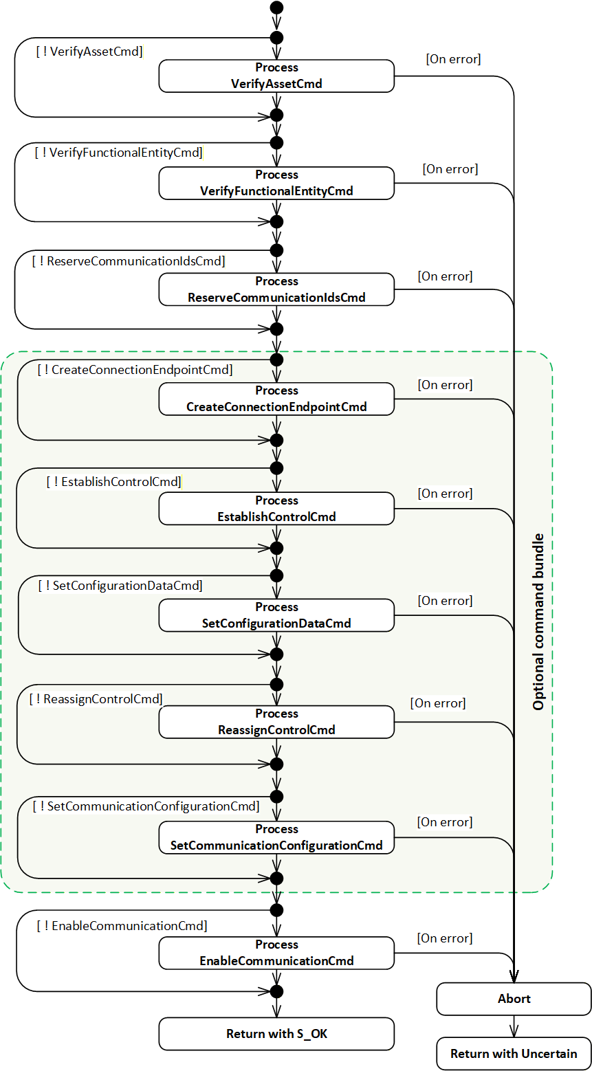
A Client calling the EstablishConnections Method may provide multiple commands and the required Arguments for each command. If multiple commands are provided in a single call, the individual commands shall be processed in the order VerifyAssetCmd, VerifyFunctionalEntityCmd, ReserveCommunicationIdsCmd, CreateConnectionEndpointCmd, EstablishControlCmd, SetConfigurationDataCmd, ReassignControlCmd, SetCommunicationConfigurationCmd, EnableCommunicationCmd, which is illustrated in Figure 20.
A Client may issue the same command in consecutive EstablishConnections Calls, e.g., to apply large configuration data in multiple Calls with SetConfigurationDataCmd.
If the processing of a command results in an error, the processing of the command sequence shall be stopped at the command that caused the error, and the EstablishConnections Method Call shall be aborted, as described in 6.2.4.3.11.
An AutomationComponent may support individual commands in EstablishConnections Method Calls or may require that certain commands be bundled in a single EstablishConnections Method Call. If an AutomationComponent requires bundled commands, the CommandBundleRequired capability shall be provided and set to TRUE (see 6.2.6). The set of bundled commands is defined as follows: CreateConnectionEndpointCmd, EstablishControlCmd, SetConfigurationDataCmd, ReassignControlCmd, and SetCommunicationConfigurationCmd. The commands CreateConnectionEndpointCmd and SetCommunicationConfigurationCmd are mandatory in the bundle; the remaining commands are optional. An AutomationComponent requiring bundled commands shall return Bad_InvalidArgument for any command in the set of bundled commands that is issued individually, i.e., not issued in a bundle.
How the commands are processed is described in Clauses 6.2.4.3.2 to 6.2.4.3.10.
6.2.4.3.2 Command VerifyAssetCmd
If CommandMask VerifyAssetCmd is set, the EstablishConnections implementation shall execute the IAssetRevisionType VerifyAsset Method for each element in the AssetVerifications array. The VerifyAsset Method shall be called on each AssetToVerify, supplying the VerificationMode, ExpectedVerificationVariables and ExpectedAdditionalVerificationVariables as Method Arguments.
The StatusCode returned by the VerifyAsset Method and the values of its output Arguments VerificationResult, VerificationVariablesErrors, and VerificationAdditionalVariablesErrors shall be stored in the appropriate elements in AssetVerificationResults (see 10.6).
Once all array processing is complete, if at least one of the following conditions is true:
AssetToVerify was unknown or invalid,
at least one of the returned AssetVerificationResults VerificationResult equals NotSet, Mismatch, or Compatible when ExpectedVerificationResult requires Match,
at least one VerifyAsset Method execution returned an error,
then the EstablishConnections implementation shall abort processing of additional commands as described in 6.2.4.3.11.
The possible StatusCodes related to the command VerifyAssetCmd are formally defined in Table 10. The StatusCodes related to individual verification Variables are formally defined in Table 33 and Table 34.
6.2.4.3.3 Command VerifyFunctionalEntityCmd
If CommandMask VerifyFunctionalEntityCmd is set, the EstablishConnections implementation shall execute the FunctionalEntityType Verify Method for each element in ConnectionEndpointConfigurations with a non-empty ExpectedVerificationVariables array. For elements with a null or empty ExpectedVerificationVariables array, the VerificationStatus shall be set to Good_NoData, VerificationResult to NotSet, and VerificationVariablesErrors to null or empty. The Method shall be called on the FunctionalEntity identified by FunctionalEntityNode, supplying the ExpectedVerificationVariables as Method Argument.
The StatusCode returned by the Verify Method shall be stored in VerificationStatus, and the values of its output Arguments VerificationResult and VerificationVariablesErrors in VerificationResult and VerificationVariablesErrors (see 10.15).
If the FunctionalEntityNode was not found, the VerificationVariablesErrors shall be set to null or empty, and the VerificationResult shall be set to Mismatch.
Once all array processing is complete, if any one of the following conditions applies:
at least one FunctionalEntityNode was not found;
at least one VerificationResult equals Mismatch;
at least one VerificationResult equals NotSet, and VerificationVariablesErrors is populated;
at least one Verify Method execution returned an error;
the EstablishConnections implementation shall abort the processing of subsequent commands as described in 6.2.4.3.11.
The possible StatusCodes for the FunctionalEntityNodeResult are formally defined in Table 11. The possible StatusCodes for VerificationStatus are formally defined in Table 44. The possible StatusCodes for VerificationVariablesErrors are formally defined in Table 45.
6.2.4.3.4 Command ReserveCommunicationIdsCmd
6.2.4.3.4.1 General
If CommandMask ReserveCommunicationIdsCmd is set, the EstablishConnections implementation shall reserve communication model identifiers for each element in ReserveCommunicationIds.
6.2.4.3.4.2 PubSub
For a PubSub communication model, a structure of type PubSubReserveCommunicationIds2DataType (see 10.43.4) shall be used.
The EstablishConnections implementation shall reserve the requested number of IDs for both WriterGroups and DataSetWriters for each requested TransportProfileUri. For additional details, see OPC 10000-14 ReserveIds Method, including error definitions.
If any error occurs, the EstablishConnections implementation shall abort processing as described in 6.2.4.3.11.
The EstablishConnections implementation shall return the default value for each requested TransportProfileUri for the PublisherId, the reserved WriterGroupIds, and DataSetWriterIds in the output Argument ReserveCommunicationIdsResults. Additionally, if the RequestTransportSpecificInfo is set to TRUE in the request for the given TransportProfileUri, it shall also return a non-null TransportSpecificInfo. In the case of UDP-UADP, this will be a UDP port number used to receive UDP unicast traffic.
The possible StatusCodes for the ReserveCommunicationIdsResults Result are formally defined in Table 18.
6.2.4.3.4.3 Client Server
This clause may be defined in a future version of this document.
6.2.4.3.5 Command CreateConnectionEndpointCmd
If CommandMask CreateConnectionEndpointCmd is set, the EstablishConnections Method shall create a ConnectionEndpoint or shall verify and update a preconfigured ConnectionEndpoint for each element in ConnectionEndpointConfigurations (see 10.14) with the Parameter defined in ConnectionEndpoint (see 10.16).
The EstablishConnections implementation shall set ConnectionEndpointConfigurationResults ConnectionEndpointResult on errors as specified in Table 12.
If IsPreconfigured is set to FALSE, the EstablishConnections implementation shall create a ConnectionEndpoint in the ConnectionEndpoints Folder of the FunctionalEntity identified by FunctionalEntityNode. The created ConnectionEndpoint shall be of the subtype specified in ConnectionEndpointTypeId. The BrowseName shall be set to Name, and all Variables shall be set according to Parameter. The appropriate entries in InputVariables and OutputVariables shall be populated.
If IsPreconfigured is set to TRUE, a preconfigured ConnectionEndpoint (see 5.5.5) shall exist with a BrowseName that matches Name in the ConnectionEndpoints Folder of the FunctionalEntity identified by FunctionalEntityNode. Its ConnectionEndpointTypeId, InputVariables and OutputVariables shall match what is specified in Parameter. IsPersistent, CleanupTimeout, and RelatedEndpoint of the preconfigured ConnectionEndpoint shall be set according to Parameter.
The implementation shall return the NodeId of the ConnectionEndpoint in the corresponding element in ConnectionEndpointConfigurationResults. If additional commands in the EstablishConnections Method sequence are present, this NodeId shall be used.
The EstablishConnections implementation shall stop processing this command on the first error and abort processing as described in 6.2.4.3.11.
The possible StatusCodes for the FunctionalEntityNodeResult are formally defined in Table 11. The possible StatusCodes for the ConnectionEndpointResult are formally defined in Table 12.
6.2.4.3.6 Command EstablishControlCmd
If CommandMask EstablishControlCmd is set, the EstablishConnections implementation shall call the EstablishControl Method on each element in ControlGroups for each element in ConnectionEndpointConfigurations. If ControlGroups is null or empty, EstablishControlResult shall be set to null or empty (see 10.15).
This command shall pass the ApplicationUri of the Session associated with the EstablishConnections Method Call as LockContext Argument to EstablishControl (see 6.5.3).
The EstablishConnections implementation shall stop processing this command on the first error and shall abort processing as described in 6.2.4.3.11.
The possible StatusCodes for the EstablishControlResult are formally defined in Table 13. The possible StatusCodes for the FunctionalEntityNodeResult are formally defined in Table 11. The possible StatusCodes for the ConnectionEndpointResult are formally defined in Table 12.
6.2.4.3.7 Command SetConfigurationDataCmd
If CommandMask SetConfigurationDataCmd is set, the EstablishConnections implementation shall apply the Value to the Key for each element in ConnectionEndpointConfigurations and each element in ConfigurationData. If the ConnectionEndpoint related to ConfigurationData has IsPersistent set, SetStoredVariables (see 6.4.6.3) shall be called for all Variables indicated by Key having the NonVolatile bit in the AccessLevelEx Attribute not set. If ConfigurationData is empty, ConfigurationDataResult shall be set to null or empty (see 10.15).
The EstablishConnections implementation shall stop processing this command on the first error and abort processing as described in 6.2.4.3.11.
The possible StatusCodes for the ConfigurationDataResult are formally defined in Table 14. The possible StatusCodes for the FunctionalEntityNodeResult are formally defined in Table 11. The possible StatusCodes for the ConnectionEndpointResult are formally defined in Table 12.
6.2.4.3.8 Command ReassignControlCmd
If CommandMask ReassignControlCmd is set, the EstablishConnections implementation shall call the ReassignControl Method on each element in ControlGroups for each element in ConnectionEndpointConfigurations. If ControlGroups is null or empty, ReassignControlResult shall be set to null or empty (see 10.15).
This command shall pass the string representation of the NodeId of the ConnectionEndpoint as LockContext Argument to ReassignControl.
The EstablishConnections implementation shall stop processing this command on the first error and shall abort processing as described in 6.2.4.3.11.
The possible StatusCodes for the ReassignControlResult are formally defined in Table 15. The possible StatusCodes for the FunctionalEntityNodeResult are formally defined in Table 11. The possible StatusCodes for the ConnectionEndpointResult are formally defined in Table 12.
6.2.4.3.9 Command SetCommunicationConfigurationCmd
6.2.4.3.9.1 General
If CommandMask SetCommunicationConfigurationCmd is set, the EstablishConnections implementation shall apply the communication model configuration supplied in CommunicationConfigurations in an atomic operation.
6.2.4.3.9.2 PubSub
The communication configuration applied in the case of a PubSub communication model is a structure of the type PubSubCommunicationConfigurationDataType (see 10.10.3).
The result of applying the communication configuration in the case of a PubSub communication model is a structure of the type PubSubCommunicationConfigurationResultDataType (see 10.11.3).
The EstablishConnections implementation shall process the supplied PubSubConfiguration with RequireCompleteUpdate and ConfigurationReferences in an atomic operation according to the behaviour of the CloseAndUpdate Method specified by OPC 10000-14. It shall set the overall processing result in the Result field of the result structure and the returned ChangesApplied, ReferenceResults, ConfigurationValues, and ConfigurationObjects in other corresponding fields of that structure.
If an error is returned, the EstablishConnections implementation shall abort processing as described in 6.2.4.3.11.
The SetCommunicationConfigurationCmd will apply the PubSubConfiguration, including the values of all Enabled flags for the configuration elements. Depending on the values of the Enabled flags, this may result in overall enabled PubSub communication without passing the EnableCommunicationCmd or parts of the PubSub communication being enabled while others are disabled.
The EstablishConnections implementation shall create the ToDataSetReader and ToDataSetWriter References according to the link information supplied in ConnectionEndpointConfigurations CommunicationLinks (see 10.13). If the PubSub configuration model is not exposed by this Server, this Reference may point to a Node that is not accessible. If the Reference cannot be created, an appropriate StatusCode shall be set in the appropriate element in ConnectionEndpointConfigurationResults CommunicationLinksResult, and the EstablishConnections implementation shall abort processing as described in 6.2.4.3.11.
The EstablishConnections implementation shall verify the SubscribedDataSet associated with the referenced DataSetReader for each element in ConnectionEndpointConfigurations having a ToDataSetReader Reference.
If ExpectedSubscribedDataSetVersion MajorVersion is 0 (for the definition of MajorVersion, see OPC 10000-14), no verification shall be performed. If ExpectedSubscribedDataSetVersion MinorVersion is 0 (for the definition of MinorVersion, see OPC 10000-14), the verification for MinorVersion shall be skipped. If the ExpectedSubscribedDataSetVersion does not match the version of the associated SubscribedDataSet, the appropriate element in ConnectionEndpointConfigurationResults CommunicationLinksResult shall be set to Bad_ConfigurationError, and the EstablishConnections implementation shall abort processing as described in 6.2.4.3.11
If InputVariableIds is used, and at least one Variable is not contained in the associated SubscribedDataSet, the appropriate element in ConnectionEndpointConfigurationResults CommunicationLinksResult shall be set to Bad_NoMatch, and the EstablishConnections implementation shall abort processing as described in 6.2.4.3.11.
The EstablishConnections implementation shall verify the PublishedDataSet associated with the referenced DataSetWriter for each element in ConnectionEndpointConfigurations having a ToDataSetWriter Reference.
If ExpectedPublishedDataSetVersion MajorVersion is 0, no verification shall be performed. If ExpectedPublishedDataSetVersion MinorVersion is 0, the verification for MinorVersion shall be skipped. If the ExpectedPublishedDataSetVersion does not match the version of the associated PublishedDataSet, the appropriate element in ConnectionEndpointConfigurationResults CommunicationLinksResult shall be set to Bad_ConfigurationError, and the EstablishConnections implementation shall abort processing as described in 6.2.4.3.11
If OutputVariableIds is used, and at least one Variable is not contained in the associated PublishedDataSet, the appropriate element in ConnectionEndpointConfigurationResults CommunicationLinksResult shall be set to Bad_NoMatch, and the EstablishConnections implementation shall abort processing as described in 6.2.4.3.11.
The EstablishConnections implementation shall verify that ConnectionEndpoints with their IsPersistent Property set to TRUE reference a DataSetReader and/or DataSetWriter which are persisted, including all parent Objects, i.e., WriterGroup, ReaderGroup, PubSubConnection and PublishSubscribe (see NotPersisted in OPC 10000-14). If the IsPersistent Property is set to FALSE, the EstablishConnections implementation shall verify that the DataSetReader and/or DataSetWriter are not persisted (see NotPersisted in OPC 10000-14). Otherwise, Bad_InvalidState shall be set in the appropriate element in ConnectionEndpointConfigurationResults CommunicationLinksResult, and the EstablishConnections implementation shall abort processing as described in 6.2.4.3.11.
If communication configuration exceeds capabilities (PublisherCapabilities, SubscriberCapabilities or ComponentCapabilities) of the AutomationComponent, FunctionalEntities, InputData or OutputData, or if communication configuration cannot be applied, Bad_ConfigurationError shall be set in the Result field of the result structure, and the EstablishConnections implementation shall abort processing as described in 6.2.4.3.11.
In the ConnectionEndpointConfigurationResults, the possible StatusCodes for the FunctionalEntityNodeResult are formally defined in Table 11. The possible StatusCodes for the ConnectionEndpointResult are formally defined in Table 12. The possible StatusCodes for the CommunicationLinksResult are formally defined in Table 16.
The possible StatusCodes for the CommunicationConfigurationResults Result are formally defined in Table 19.
Standard OPC UA Diagnostics can be used to obtain additional information related to any PubSub configuration errors.
6.2.4.3.9.3 Client Server
This clause may be defined in a future version of this document.
6.2.4.3.10 Command EnableCommunicationCmd
6.2.4.3.10.1 General
If CommandMask EnableCommunicationCmd is set, the EstablishConnections implementation shall enable all communication model-specific Objects related to the ConnectionEndpoints in an atomic operation.
6.2.4.3.10.2 PubSub
The EstablishConnections implementation shall enable the DataSetReader and DataSetWriter referenced by ToDataSetReader and/or ToDataSetWriter References for each element in ConnectionEndpointConfigurations. It shall also ensure that the parent Objects (WriterGroup, ReaderGroup, PubSubConnection, and PublishSubscribe) are enabled.
If enabling any communication model-specific Objects fails, the EstablishConnections implementation shall abort processing as described in 6.2.4.3.11.
If enabling a ConnectionEndpoint would lead to multiple DataSetReaders being enabled that reference the same TargetVariable(s), the EstablishConnections implementation shall abort processing as described in 6.2.4.3.11.
The possible StatusCodes for the FunctionalEntityNodeResult are formally defined in Table 11. The possible StatusCodes for the ConnectionEndpointResult are formally defined in Table 12. The possible StatusCodes for the EnableCommunicationResult are formally defined in Table 17.
6.2.4.3.10.3 Client Server
This clause may be defined in a future version of this document.
6.2.4.3.11 Abort
The EstablishConnections implementation shall abort processing if one of the issued commands fails; see the individual command behaviour descriptions in Clauses 6.2.4.3.2 to 6.2.4.3.10. No further commands requested for this Method Call shall be executed. The result of the commands executed with this Method Call shall be rolled back according to Table 21.
| Command | Rollback action |
| VerifyAssetCmd | None |
| VerifyFunctionalEntityCmd | None |
| ReserveCommunicationIdsCmd | None |
| CreateConnectionEndpointCmd | All ConnectionEndpoints in the context of this Method Call shall be deleted. |
| EstablishControlCmd | All requested ControlGroups requested in the context of this Method Call shall be released by calling ReleaseControl. All Control References created shall be deleted. |
| SetConfigurationDataCmd | None Note: Any settings that have been applied will remain. |
| ReassignControlCmd | None |
| SetCommunicationConfigurationCmd | All communication configuration and References created in the context of this Method Call shall be deleted. |
| EnableCommunicationCmd | All communication configuration Objects that were enabled in the context of this Method Call shall be disabled. |
The Method shall set the appropriate StatusCodes for not executed commands to Bad_NothingToDo and return with an Uncertain result.
There is no rollback provided by the Method over multiple Method calls; such a rollback is the responsibility of the caller of the Method (e.g., the ConnectionManager). The caller of the Method can use the CloseConnections Method to issue a complete rollback.
6.2.5 CloseConnections method
6.2.5.1 CloseConnections signature
This Method disables one or more Connections. Optionally, it also removes these Connections. It is recommended that this Method has the execute privilege for the well-known Role ConnectionAdmin as defined in Clause 5.9.
The signature of the Method is described below, and the arguments are described in Table 22.
Signature
	CloseConnections (
	  [in] 0:NodeId[]			ConnectionEndpoints,
	  [in] 0:Boolean			Remove,
	  [out] 0:StatusCode[]		Results
);| Argument | Description |
| ConnectionEndpoints | The list of Connections to be closed. |
| Remove | When TRUE, the Objects dynamically created for the Connection are removed. |
| Results | The results of closing the Connections identified by the ConnectionEndpoints argument, see Table 24. The length of this array shall match the length of the ConnectionEndpoints list. Clients may inspect this list to determine which Connections failed to be closed. |
The possible Method result codes are formally defined in Table 23.
| Result Code | Description |
| Uncertain | There was at least one error or warning for one of the Connections. Results will contain additional information. |
The possible Results StatusCodes are formally defined in Table 24.
| Result Code | Description |
| Bad_NodeIdUnknown | The NodeId for the requested ConnectionEndpoint does not exist in the Server address space. |
| Bad_NodeIdInvalid | The syntax of the NodeId for the requested ConnectionEndpoint was invalid. |
| Bad_InvalidArgument | The NodeId for the requested ConnectionEndpoint was not a ConnectionEndpoint. |
The CloseConnections Method representation in the AddressSpace is formally defined in Table 25.
| Attribute | Value | ||||
| BrowseName | 3:CloseConnections | ||||
| References | Node Class | BrowseName | DataType | TypeDefinition | Other |
|---|---|---|---|---|---|
| 0:HasProperty | Variable | 0:InputArguments | 0:Argument[] | 0:PropertyType | M |
| 0:HasProperty | Variable | 0:OutputArguments | 0:Argument[] | 0:PropertyType | M |
| 0:GeneratesEvent | ObjectType | 2:AuditUpdateMethodResultEventType | Defined in 8.2 | ||
| ConformanceUnits | |||||
|---|---|---|---|---|---|
| UAFX AutomationComponent Base |
6.2.5.2 CloseConnections behaviour
The Method implementation shall disable all communication model Objects for each element in ConnectionEndpoints in an atomic operation. For additional details on ConnectionEndpoints, see 6.6, and PubSubConnectionEndpoints, see 6.6.3.
If PubSub is used as the communication model for a ConnectionEndpoint, the Method implementation shall only disable the DataSetReader and DataSetWriter referenced by ToDataSetReader and/or ToDataSetWriter References if no further References from other ConnectionEndpoints exist. Their parent Objects (WriterGroup, ReaderGroup, PubSubConnection, and PublishSubscribe) shall be left in their current state.
The behaviour of the Client Server communication model may be defined in a future version of this document.
The CleanupTimeout processing shall be disabled.
If Remove is TRUE, the Method implementation shall remove what has been dynamically created by the EstablishConnections Method Call(s) related to the ConnectionEndpoints. This includes any configuration specific to the utilised communication model, all related communication model Objects if not referenced from other ConnectionEndpoints, the ConnectionEndpoints, and all persisted items. In addition, all ControlGroups-based restrictions placed on Objects shall be released. Preconfigured Objects or Objects referenced by other ConnectionEndpoints shall not be removed.
What occurs with the ConfigurationData that was applied when establishing the ConnectionEndpoints is vendor-specific.
6.2.6 AutomationComponentCapabilitiesType
The AutomationComponentCapabilitiesType extends the FolderType defined in OPC 10000-5. It shall be restricted to holding only Variables that reflect the capabilities of the AutomationComponentType.
The AutomationComponentCapabilitiesType is formally defined in Table 26.
| Attribute | Value | ||||
| BrowseName | 3:AutomationComponentCapabilitiesType | ||||
| IsAbstract | False | ||||
| References |
Node
Class | BrowseName | DataType | TypeDefinition | Other |
|---|---|---|---|---|---|
| Subtype of the 0:FolderType defined in OPC 10000-5 | |||||
| 3:HasCapability | Variable | 3:<Capability> | 0:BaseDataType | 0:BaseDataVariableType | OP |
| 3:HasCapability | Variable | 3:SupportsPersistence | 0:Boolean | 0:BaseDataVariableType | O |
| 3:HasCapability | Variable | 3:MaxFunctionalEntities | 0:UInt32 | 0:BaseDataVariableType | O |
| 3:HasCapability | Variable | 3:MaxConnections | 0:UInt32 | 0:BaseDataVariableType | O |
| 3:HasCapability | Variable | 3:MinConnections | 0:UInt32 | 0:BaseDataVariableType | O |
| 3:HasCapability | Variable | 3:MaxConnectionsPerCall | 0:UInt32 | 0:BaseDataVariableType | O |
| 3:HasCapability | Variable | 3:CommandBundleRequired | 0:Boolean | 0:BaseDataVariableType | O |
| ConformanceUnits | |||||
|---|---|---|---|---|---|
| UAFX AutomationComponent Base |
<Capability> - is an OptionalPlaceholder (defined in OPC 10000-3 ) to indicate that additional capabilities may be added by this document, by a companion specification or by a vendor application. These capabilities shall include a Description, and they follow all of the rules associated with an OptionalPlaceholder.
The optional SupportsPersistence indicates whether this AutomationComponent supports persistent Connections. For additional details on persistence, see 6.6. If this capability is not present or set to FALSE, the AutomationComponent does not support persistent Connections.
The optional MaxFunctionalEntities indicates the maximum number of FunctionalEntities that the AutomationComponent can support.
The optional MaxConnections indicates the maximum number of Connections that the AutomationComponent can support. This number may be further restricted based on the type of Connections being provided (i.e., a high-speed Connection might further reduce the number of available Connections).
The optional MinConnections indicates the minimum number of Connections that the AutomationComponent can always guarantee. MinConnections shall be less than or equal to MaxConnections (if both exist). The actual number of Connections that might exist may be some number between the MinConnections and the MaxConnections.
The optional MaxConnectionsPerCall indicates the maximum number of Connections that can be established in a single EstablishConnections Call (see 6.2.4). MaxConnectionsPerCall shall be less than or equal to MaxConnections (if both exist).
If MaxFunctionalEntities, MaxConnections, and MaxConnectionsPerCall are not present, then no limit is specified.
The optional CommandBundleRequired indicates whether this AutomationComponent requires a single Method Call for bundled commands when EstablishConnections is called (see 6.2.4.3.1). If the capability is not present or set to FALSE, the AutomationComponent supports individual calls.
6.2.7 PublisherCapabilitiesType
The PublisherCapabilitiesType is a subtype of the BaseObjectType. It is used to contain the various Publisher capabilities that can be supported. An instance of this ObjectType groups the capabilities and can be deployed as part of any Object that desires to expose a range of capabilities that are supported by that Object.
It is formally defined in Table 27.
| Attribute | Value | ||||
| BrowseName | 3:PublisherCapabilitiesType | ||||
| IsAbstract | False | ||||
| References | Node Class | BrowseName | DataType | TypeDefinition | Other |
|---|---|---|---|---|---|
| Subtype of the 0:BaseObjectType defined in OPC 10000-5 | |||||
| 0:HasComponent | Variable | 3:SupportedPublishingIntervals | 3:IntervalRange[] | 0:BaseDataVariableType | M |
| 0:HasComponent | Variable | 3:SupportedQos | 3:PublisherQosDataType[] | 0:BaseDataVariableType | M |
| 0:HasComponent | Variable | 3:PreconfiguredPublishedDataSets | 0:String[] | 0:BaseDataVariableType | M |
| 0:HasComponent | Variable | 3:PreconfiguredDataSetOnly | 0:Boolean | 0:BaseDataVariableType | M |
| ConformanceUnits | |||||
|---|---|---|---|---|---|
| UAFX AutomationComponent PublisherCapabilities Base | |||||
SupportedPublishingIntervals provides the supported intervals for publishing. An empty array indicates that no restrictions are defined by this instance.
SupportedQos provides the supported Quality of Service settings. An empty array indicates that no restrictions are defined by this instance.
PreconfiguredPublishedDataSets provides the names of preconfigured PublishedDataSets (see 5.5.5), where the name is the string part of the BrowseName of a PublishedDataSet that is listed in the PublishedDataSets Folder tree of the PublishSubscribe Object (see OPC 10000-14). If PublisherCapabilities is referenced from a FunctionalEntity (see 6.4.2) or OutputData (see 6.4.5), a preconfigured PublishedDataSet shall only reference OutputVariables of this FunctionalEntity and its sub-FunctionalEntities. If the PublisherCapabilities is referenced from an AutomationComponent, a preconfigured PublishedDataSet shall only reference OutputVariables from FunctionalEntities that are part of the AutomationComponent. When the preconfigured PublishedDataSet is used in a ConnectionConfigurationSet, Connections shall be established to one or more of the FunctionalEntities whose variables are present in the DataSet. An empty array indicates that no preconfigured PublishedDataSets are defined by this instance.
PreconfiguredDataSetOnly, if set to TRUE, indicates that the Publisher supports publishing of preconfigured PublishedDataSets only. If set to FALSE, the Publisher supports publishing of customised PublishedDataSets as well as preconfigured PublishedDataSets.
6.2.8 SubscriberCapabilitiesType
The SubscriberCapabilitiesType is a subtype of the BaseObjectType. It is used to contain the various Subscriber capabilities that can be supported. An instance of this ObjectType groups the capabilities and can be deployed as part of any Object that desires to expose a range of capabilities that are supported by that Object.
It is formally defined in Table 28.
| Attribute | Value | ||||
| BrowseName | 3:SubscriberCapabilitiesType | ||||
| IsAbstract | False | ||||
| References | Node Class | BrowseName | DataType | TypeDefinition | Other |
|---|---|---|---|---|---|
| Subtype of the 0:BaseObjectType defined in OPC 10000-5 | |||||
| 0:HasComponent | Variable | 3:SupportedPublishingIntervals | 3:IntervalRange[] | 0:BaseDataVariableType | M |
| 0:HasComponent | Variable | 3:SupportedQos | 3:SubscriberQosDataType[] | 0:BaseDataVariableType | M |
| 0:HasComponent | Variable | 3:SupportedMessageReceiveTimeouts | 3:IntervalRange[] | 0:BaseDataVariableType | M |
| 0:HasComponent | Variable | 3:PreconfiguredSubscribedDataSets | 0:String[] | 0:BaseDataVariableType | M |
| 0:HasComponent | Variable | 3:PreconfiguredDataSetOnly | 0:Boolean | 0:BaseDataVariableType | M |
| ConformanceUnits | |||||
|---|---|---|---|---|---|
| UAFX AutomationComponent SubscriberCapabilities Base |
SupportedPublishingIntervals provides the intervals for publications, which this Subscriber is able to receive. An empty array indicates that no restrictions are defined by this instance.
SupportedQos provides the supported Quality of Service settings. An empty array indicates that no restrictions are defined by this instance.
SupportedMessageReceiveTimeouts provides the supported timeouts for receiving messages. An empty array indicates that no restrictions are defined by this instance.
PreconfiguredSubscribedDataSets provides the names of preconfigured StandaloneSubscribedDataSets (see 5.5.5), where the name is the string part of the BrowseName of a StandaloneSubscribedDataSet that is listed in the SubscribedDataSets Folder tree of the PublishSubscribe Object (see OPC 10000-14). If SubscriberCapabilities is referenced from a FunctionalEntity (see 6.4.2) or InputData (see 6.4.4), a preconfigured StandaloneSubscribedDataSet shall only reference InputVariables from the FunctionalEntity and its sub-FunctionalEntities. If the SubscriberCapabilities is referenced from an AutomationComponent, a preconfigured StandaloneSubscribedDataSet shall only reference InputVariables from FunctionalEntities that are part of the AutomationComponent. When the preconfigured StandaloneSubscribedDataSet is used in a ConnectionConfigurationSet, Connections shall be established to one or more of the FunctionalEntities whose variables are present in the DataSet. An empty array indicates that no preconfigured StandaloneSubscribedDataSets are defined by this instance.
PreconfiguredDataSetOnly, if set to TRUE, indicates that the Subscriber only supports subscribing with preconfigured StandaloneSubscribedDataSets. If set to FALSE, the subscriber supports subscribing with customised SubscribedDataSets as well as preconfigured StandaloneSubscribedDataSets.
6.3 FxAssetType definition
6.3.1 Overview
Figure 21 provides an illustration of the FxAssetType model. The figure includes an illustration of the nodes that are added via the Interfaces.
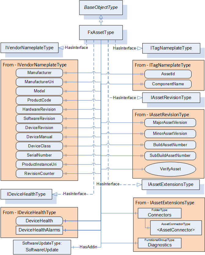
6.3.2 FxAssetType definition
The FxAssetType provides general information as defined in OPC 10000-100. It also includes additional information that is defined as an Interface. Being defined as an Interface allows other device models to include what is required for OPC UA FX Asset modelling without having to implement the FxAssetType Object directly. Conformance testing shall test that the required information, defined by the Interfaces included in the FxAssetType, is available, not that the Object is of FxAssetType. Any Object that implements all of the Interfaces defined in FxAssetType is considered an Asset.
Additional References are defined as part of the model to show relationships between Assets, within Assets, and between Assets and FunctionalEntities and the overall AutomationComponent model (see 11.1).
The FxAssetType is formally defined in Table 29.
| Attribute | Value | ||||
| BrowseName | 3:FxAssetType | ||||
| IsAbstract | False | ||||
| References |
Node
Class | BrowseName | DataType | TypeDefinition | Other |
|---|---|---|---|---|---|
| Subtype of the 0:BaseObjectType defined in OPC 10000-5 | |||||
| 0:HasInterface | ObjectType | 5:IVendorNameplateType | |||
| Applied from IVendorNameplateType (defined in OPC 10000-100 ) | |||||
|---|---|---|---|---|---|
| 0:HasProperty | Variable | 5:Manufacturer | 0:LocalizedText | 0:PropertyType | O |
| 0:HasProperty | Variable | 5:ManufacturerUri | 0:String | 0:PropertyType | O |
| 0:HasProperty | Variable | 5:Model | 0:LocalizedText | 0:PropertyType | O |
| 0:HasProperty | Variable | 5:ProductCode | 0:String | 0:PropertyType | O |
| 0:HasProperty | Variable | 5:HardwareRevision | 0:String | 0:PropertyType | O |
| 0:HasProperty | Variable | 5:SoftwareRevision | 0:String | 0:PropertyType | O |
| 0:HasProperty | Variable | 5:DeviceRevision | 0:String | 0:PropertyType | O |
| 0:HasProperty | Variable | 5:DeviceManual | 0:String | 0:PropertyType | O |
| 0:HasProperty | Variable | 5:DeviceClass | 0:String | 0:PropertyType | O |
| 0:HasProperty | Variable | 5:SerialNumber | 0:String | 0:PropertyType | O |
| 0:HasProperty | Variable | 5:ProductInstanceUri | 0:String | 0:PropertyType | O |
| 0:HasProperty | Variable | 5:RevisionCounter | 0:Int32 | 0:PropertyType | O |
| 0:HasInterface | ObjectType | 5:ITagNameplateType | |||
| Applied from ITagNameplateType (defined in OPC 10000-100 ) | |||||
|---|---|---|---|---|---|
| 0:HasProperty | Variable | 5:AssetId | 0:String | 0:PropertyType | O |
| 0:HasProperty | Variable | 5:ComponentName | 0:LocalizedText | 0:PropertyType | O |
| 0:HasInterface | ObjectType | 3:IAssetRevisionType | |||
| Applied from IAssetRevisionType | |||||
|---|---|---|---|---|---|
| 0:HasProperty | Variable | 3:MajorAssetVersion | 0:UInt16 | 0:PropertyType | O |
| 0:HasProperty | Variable | 3:MinorAssetVersion | 0:UInt16 | 0:PropertyType | O |
| 0:HasProperty | Variable | 3:BuildAssetNumber | 0:UInt16 | 0:PropertyType | O |
| 0:HasProperty | Variable | 3:SubBuildAssetNumber | 0:UInt16 | 0:PropertyType | O |
| 0:HasComponent | Method | 3:VerifyAsset | Defined in 6.3.3 | O | |
| 0:HasInterface | ObjectType | 3:IAssetExtensionsType | |||
| Applied from IAssetExtensionsType | |||||
|---|---|---|---|---|---|
| 0:HasComponent | Object | 3:Connectors | 0:FolderType | O | |
| 0:HasComponent | Object | 5:Diagnostics | 5:FunctionalGroupType | O | |
| 0:HasInterface | ObjectType | 5:IDeviceHealthType | |||
| Applied from IDeviceHealthType (defined in OPC 10000-100) | |||||
|---|---|---|---|---|---|
| 0:HasComponent | Variable | 5:DeviceHealth | 5:DeviceHealthEnumeration | 0:BaseDataVariableType | O |
| 0:HasComponent | Object | 5:DeviceHealthAlarms | 0:FolderType | O | |
| 0:HasAddIn | Object | 5:SoftwareUpdate | 5:SoftwareUpdateType | O | |
| ConformanceUnits | |||||
|---|---|---|---|---|---|
| UAFX FXAsset Type |
The components of the FxAssetType have additional subcomponents, which are defined in Table 30
| BrowsePath | References | NodeClass | BrowseName | DataType | TypeDefinition | Others |
| 5:Diagnostics | 0:HasComponent | Variable | 3:UpTime | 0:Duration | 0:BaseDataVariableType | O |
| 5:Diagnostics | 0:HasComponent | Variable | 3:CurrentCPUUtilization | 0:Float | 0:BaseDataVariableType | O |
| 5:Diagnostics | 0:HasComponent | Variable | 3:MaxCPUUtilization | 0:Float | 0:BaseDataVariableType | O |
| 5:Diagnostics | 0:HasComponent | Variable | 3:CurrentMemoryUtilization | 0:Float | 0:BaseDataVariableType | O |
| 5:Diagnostics | 0:HasComponent | Variable | 3:MaxMemoryUtilization | 0:Float | 0:BaseDataVariableType | O |
The display name of the Asset should be used to provide the name that an operator/engineer would expect for the Asset.
For examples of how to apply the OPC UA FX Information Model to other models, see Annex B. For examples of FxAssetType models, see Annex D.
The following are the definitions associated with the IVendorNameplateType interface; they are enclosed in quotes and included here for clarity. Their formal definition is in OPC 10000-100. Additional notes are provided for recommended usage within this model.
“Manufacturer provides the name of the company that manufactured the item to which this Interface is applied.”
“ManufacturerUri provides a unique identifier for this company. This identifier should be a fully qualified domain name; however, it may be a GUID or similar construct that ensures global uniqueness.”
“Model provides the name of the product.”
“ProductCode provides a unique combination of numbers and letters used to identify the product. It may be the order information displayed on type shields or in ERP systems.”
“HardwareRevision provides the revision level of the hardware of an Asset.”
“SoftwareRevision provides the version or revision level of the software component, the software/firmware of a hardware component, or the software/firmware of the Device.”
“DeviceRevision provides the overall revision level of a hardware component or the Device. As an example, this Property can be used in ERP systems together with the ProductCode Property.”
“DeviceManual allows specifying the address of the user manual for an Asset. It may be a pathname in the file system or a URL (Web address).”
“DeviceClass indicates in which domain or for what purpose a certain ComponentType is used. Examples are “ProgrammableController”, “RemoteIO”, and “TemperatureSensor”. This standard does not predefine any DeviceClass names. More specific standards that utilise this Interface will likely introduce such classifications.”
Within this model, this information is typically used for display purposes only. It is recommended that if this Property is provided, the string should be from some standardised dictionary.
“SerialNumber is a unique production number of the manufacturer of the Asset. This is often stamped on the outside of a physical component and may be used for traceability and warranty purposes.”
“ProductInstanceUri is a globally unique resource identifier provided by the manufacturer. This is often stamped on the outside of a physical component and may be used for traceability and warranty purposes. The maximum length is 255 characters. The syntax of the ProductInstanceUri is: <ManufacturerUri>/<any string>, where <any string> is unique among all instances using the same ManufacturerUri.”
Within this model, ProductInstanceUri, SerialNumber, or both shall be provided for Assets listed directly in the Assets Folder of the AutomationComponent.
“RevisionCounter is an incremental counter indicating the number of times the configuration data within an Asset has been modified.”
Within this model, this configuration data may be one of the items defined in this document, but more likely, it is a configuration item that has been added to the asset model either as part of a companion specification or as part of an instance.
The following two definitions are from the ITagNameplateType interface. They are enclosed in quotes and included here for clarity. Their formal definition is in OPC 10000-100. Additional notes are provided for recommended usage within OPC UA FX.
“AssetId is a user-writable alphanumeric character sequence uniquely identifying a component. The ID is provided by the integrator or user of the device. It typically contains an identifier in a branch use case or a user-specific naming scheme. This could be, for example, a reference to an electric scheme.“
“ComponentName is a user-writable name provided by the integrator or user of the component.”
The following two definitions are from the IDeviceHealthType interface. They are enclosed in quotes and included here for clarity. Their formal definition is in OPC 10000-100. Additional notes are provided for recommended usage within OPC UA FX.
“The DeviceHealthEnumeration DataType is an enumeration that defines the device condition.”
“DeviceHealthAlarms shall be used for instances of the DeviceHealth AlarmTypes specified in OPC 10000-100.” AlarmType instances can also be defined in other specifications, such as OPC 10000-110 or this document.
The IDeviceHealthType Interface shall be implemented on top-level Assets and any other Assets that maintain their own status information. DeviceHealth of the top-level Assets is aggregated into AggregatedDeviceHealth (see 9.1.2). Whether nested Assets aggregate their DeviceHealth into DeviceHealth of their parent Asset is vendor-specific and is further described in OPC 10000-110 (e.g., for redundant nested Assets, one might fail without the parent Asset failing).
SoftwareUpdate is an AddIn (see OPC 10000-100) that defines support for firmware or software updates. This optional AddIn should be included in any Asset that includes firmware or software that can be upgraded or changed. For a definition of the AddIn concept, see OPC 10000-3.
The following definitions are associated with the IAssetRevisionType interface (see 7.3).
The MajorAssetVersion shall be updated for major changes in an Asset that may break compatibility with previous versions.
The MinorAssetVersion shall be updated for minor changes in an Asset that should not change the behaviour of the Asset regarding compatibility. Higher numeric values of MinorAssetVersion should be backwards compatible with lower ones, e.g., behaviour that is present in MinorAssetVersion 12 shall still be supported by MinorAssetVersion 13 or greater. An incremented MinorAssetVersion may add new behaviour which is not present in a lower MinorAssetVersion while retaining existing functionality.
The BuildAssetNumber and SubBuildAssetNumber reflect detailed information about the version of the Asset. Together with the MajorAssetVersion and MinorAssetVersion, they provide the capability to unambiguously identify a specific version of an Asset.
The following definitions are associated with the IAssetExtensionsType interface (see 7.4).
Connectors is a Folder used to group and list physical- or software-based connectors (instances of AssetConnectorType) that can be used to link multiple Assets. A connector provides more information about an Asset connection than a simple Reference can. For a formal definition of the AssetConnectorType, see 6.3.4.
Diagnostics is a FunctionalGroup (Folder) that contains Variables that report diagnostic statistics and counters (see OPC 10000-100 Recommended FunctionalGroup BrowseNames).
The UpTime Variable provides the module's uptime since the last power-on.
The CurrentCPUUtilization Variable provides the current CPU utilisation in percent (the calculation is vendor-specific).
The MaxCPUUtilization Variable provides the maximum CPU utilisation in percent since the last power-on (the calculation is vendor-specific).
The CurrentMemoryUtilization Variable provides the current memory utilisation in percent (the calculation is vendor-specific).
The MaxMemoryUtilization Variable provides the maximum memory utilisation in percent since the last power-on (the calculation is vendor-specific).
6.3.3 VerifyAsset method
The VerifyAsset Method allows a Client to verify whether an Asset’s identity and functionality meet the expectations of system engineering.
Three different modes are available for Asset verification (see VerificationMode). Each mode depends on a set of mandatory and optional Variables (see definition of AssetVerificationModeEnum in 10.4) to be present for verification. The VerifyAsset Method also accepts additional Variables for verification.
An Asset implementing the VerifyAsset Method shall at least support the VerificationMode AssetCompatibility and expose the corresponding mandatory and implemented optional Variables in its Information Model. If at least one of the optional Variables, SerialNumber and/or ProductInstanceUri, is provided, then the VerificationModes AssetIdentity and AssetIdentityAndCompatibility shall be supported.
The signature of this Method is specified below; the arguments are defined in Table 31.
Signature
	VerifyAsset (
	[in] 2:AssetVerificationModeEnum	VerificationMode,
	[in] 0:KeyValuePair[]			ExpectedVerificationVariables,
	[in] 2:NodeIdValuePair[]			ExpectedAdditionalVerificationVariables,
	[out] 2:AssetVerificationResultEnum	VerificationResult,
	[out] 0:StatusCode[]			VerificationVariablesErrors,
	[out] 0:StatusCode[]			VerificationAdditionalVariablesErrors
	);
| Argument | Description |
| VerificationMode | Mode for Asset verification: see 10.4 for a definition of the AssetVerificationModeEnum. |
| ExpectedVerificationVariables | An array of KeyValuePair containing verification Variables. Key shall be the BrowseName of the Variable to verify (relative to the Asset this Method is being called on), and Value is its expected value. A Client shall pass all mandatory and implemented optional Variables depending on VerificationMode: AssetCompatibility: IVendorNameplateType ManufacturerUri (M), IVendorNameplateType ProductCode (M), IAssetRevisionType MajorAssetVersion (M), IAssetRevisionType MinorAssetVersion (M), IAssetRevisionType BuildAssetNumber (O), IAssetRevisionType SubBuildAssetNumber (O), IVendorNameplateType HardwareRevision (O), IVendorNameplateType SoftwareRevision (O) AssetIdentity: IVendorNameplateType ManufacturerUri (M), IVendorNameplateType ProductCode (M), At least one of: IVendorNameplateType SerialNumber, IVendorNameplateType ProductInstanceUri AssetIdentityAndCompatibility: All mandatory Variables of both AssetCompatibility and AssetIdentity are mandatory for top-level Assets (those directly in the Assets Folder in the AutomationComponent). All optional Variables of AssetCompatibility are optional. |
| ExpectedAdditionalVerificationVariables | An array of NodeIdValuePair containing additional verification Variables. NodeId shall be the NodeId of the Variable to verify, and Value shall be its expected value. This array may be null or empty if no additional Variables are to be verified. The following rules shall apply to the usage of NodeIdValuePair: If NodeId refers to variables of type array, it shall be verified that Value is a matching array. If the ArrayIndex is provided, the value shall be checked against the corresponding index. If Value is null, it shall be verified that NodeId exists. The Node may be of any NodeClass, but only the NodeClass of Variable or VariableType can have a non-null value. |
| VerificationResult | The result of Asset verification is determined by the Method implementation; see 10.7 for a definition of the AssetVerificationResultEnum. The following general rule applies to determine VerificationResult: All string-type Variables shall be stripped of leading and trailing whitespaces before processing. The following specific rules apply to determine AssetCompatibility:
NotSet: Shall be returned if verification is not possible due to invalid elements in ExpectedVerificationVariables and/or ExpectedAdditionalVerificationVariables (e.g., a Variable was passed by the Client that does not exist in the Asset’s Information Model). Match: Shall be returned if all Variables in ExpectedVerificationVariables and ExpectedAdditionalVerificationVariables exist in the Information Model of this Asset and their actual values are identical to the expected values. Compatible: Shall be returned if all of the following conditions apply: The actual value of at least one ExpectedVerificationVariables does not match its expected value, but overall, the Asset is still compatible (e.g., expected IAssetRevisionType MinorAssetVersion 1, but the actual value is 2, being backwards compatible to 1). All ExpectedAdditionalVerificationVariables match their expected values. Mismatch: Shall be returned if any of the following conditions apply: The actual value of at least one ExpectedVerificationVariables does not match its expected value, and the Asset overall is not compatible. The actual value of at least one ExpectedAdditionalVerificationVariables does not match its expected value. If this value is set, VerificationVariablesErrors and/or VerificationAdditionalVariablesErrors shall be populated. The following specific rules apply to determine AssetIdentity: NotSet: See description for AssetCompatibility. Match: See description for AssetCompatibility. Compatible: Shall never be returned.
Mismatch: Shall be returned if all Variables in ExpectedVerificationVariables and ExpectedAdditionalVerificationVariables exist and the actual value of at least one does not match its expected value. The following specific rules apply to determine AssetIdentityAndCompatibility: NotSet: Shall be returned if verification of AssetCompatibility or AssetIdentity or both result in NotSet. Match: Shall be returned if both the verification of AssetIdentity and AssetCompatibility result in Match. Compatible: Shall be returned if verification of AssetIdentity results in Match and verification of AssetCompatibility results in Compatible. Mismatch: Shall be returned if verification of AssetCompatibility or AssetIdentity or both results in Mismatch. |
| VerificationVariablesErrors | An array of StatusCode corresponding to the ExpectedVerificationVariables input argument that indicates any errors that occurred during the processing of ExpectedVerificationVariables. If this array is populated, the length of this array shall match the length of ExpectedVerificationVariables. For possible values in this array, see Table 33. |
| VerificationAdditionalVariablesErrors | An array of StatusCode corresponding to the ExpectedAdditionalVerificationVariables input argument that indicates any errors that occurred during the processing of ExpectedAdditionalVerificationVariables. If this array is populated, the length of this array shall match the length of ExpectedAdditionalVerificationVariables. For possible values in this array, see Table 34. |
The possible Method result codes are formally defined in Table 32. The order in which checks are performed is vendor-specific. A bad result code in the Method (an error code in Table 32) shall result in all output arguments listed in the Method signature being empty/null. The check of provided Variables (Bad_InvalidArgument) shall take precedence over the actual checks related to the values of provided Variables.
| Result Code | Description |
| Bad_InvalidArgument | One or more arguments are invalid, or ExpectedVerificationVariables are missing Variables that are mandatory for the chosen VerificationMode (or optional, and the implementation of this Method expects them because they are implemented). |
| Bad_NotSupported | The Client specified a VerificationMode that is not supported by this Method implementation. |
| Uncertain | At least one element in ExpectedVerificationVariables and/or ExpectedAdditionalVerificationVariables is invalid or failed verification. VerificationVariablesErrors and/or VerificationAdditionalVariablesErrors will contain additional information. |
The VerificationVariablesErrors StatusCodes are formally defined in Table 33.
| Result Code | Description |
| Bad_BrowseNameInvalid | The BrowseName for the verification Variable is invalid or was passed more than once. |
| Bad_TypeMismatch | The value supplied for the verification Variable (if non-null) is not of the same type as the implemented verification Variable. |
| Bad_OutOfRange | The value supplied for the Variable is not equal to the actual value of the Variable (if non-null). |
| Good | The verification for this Variable succeeded. |
The VerificationAdditionalVariablesErrors StatusCodes are formally defined in Table 34.
| Result Code | Description |
| Bad_OutOfRange | The value supplied for the Variable is not equal to the actual value of the Variable (if non-null). |
| Bad_TypeMismatch | The value supplied for the verification Variable (if non-null) is not of the same type as the implemented verification variable. |
| Bad_NodeIdInvalid | The NodeIdValuePair contains a NodeId in its key field with an invalid syntax. |
| Bad_NodeIdUnknown | The NodeIdValuePair contains a NodeId in its key field that does not exist in the Server address space. |
| Good | The verification for this Variable succeeded. |
The VerifyAsset Method representation in the AddressSpace is formally defined in Table 35.
| Attribute | Value | ||||
| BrowseName | 3:VerifyAsset | ||||
| References | Node Class | BrowseName | DataType | TypeDefinition | Other |
|---|---|---|---|---|---|
| 0:HasProperty | Variable | 0:InputArguments | 0:Argument[] | 0:PropertyType | M |
| 0:HasProperty | Variable | 0:OutputArguments | 0:Argument[] | 0:PropertyType | M |
| ConformanceUnits | |||||
|---|---|---|---|---|---|
| UAFX IAssetRevision VerifyAsset Base |
6.3.4 AssetConnectorType definition
The AssetConnectorType provides information about physical connections that are part of an Asset. An example of these connections might be slots in which cards can be mounted or sockets to which cables can be connected. For additional examples, see Annex D. It is expected that subtypes of this type that provide or require additional Properties or Variables will be created. Figure 22 provides an illustration of the AssetConnectorType.
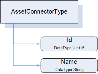
The AssetConnectorType is an abstract type and must be subtyped. It is formally defined in Table 36.
| Attribute | Value | ||||
| BrowseName | 3:AssetConnectorType | ||||
| IsAbstract | True | ||||
| References | Node Class | BrowseName | DataType | TypeDefinition | Other |
|---|---|---|---|---|---|
| Subtype of the 0:BaseObjectType defined in OPC 10000-5 | |||||
| 0:HasProperty | Variable | 3:Id | 0:UInt16 | 0:PropertyType | O |
| 0:HasProperty | Variable | 3:Name | 0:String | 0:PropertyType | O |
| 0:HasSubtype | ObjectType | 3:SlotType | Defined in 6.3.5 | ||
| 0:HasSubtype | ObjectType | 3:SocketType | Defined in 6.3.6 | ||
| 0:HasSubtype | ObjectType | 3:ClampType | Defined in 6.3.7 | ||
| 0:HasSubtype | ObjectType | 3:ClampBlockType | Defined in 6.3.8 | ||
| ConformanceUnits | |||||
|---|---|---|---|---|---|
| UAFX AssetConnector Slot Base | |||||
| UAFX AssetConnector Socket Base | |||||
| UAFX AssetConnector Clamp Base | |||||
| UAFX AssetConnector ClampBlock Base |
Id provides the (physical) ID of the connector, representing the physical location of the connector in the Asset. The use of this ID can be further explained or defined in subtypes.
Name provides the physical label that is associated with this connector. The use of Name can be further explained or defined in subtypes. For example, it might be the name of the target of this connector, the DisplayName would be slot1, and the Name would be Pump1.
Figure 23 provides an illustration of some of the possible subtypes of the AssetConnectorType.
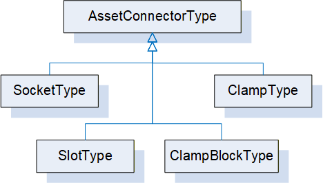
Some connector types are used to link other Assets, while other AssetConnectorTypes might be used to indicate physical connections.
6.3.5 SlotType definition
The SlotType represents a physical slot to which a module can be attached, e.g., in a modular Asset like a PLC backplane or modular IO device.
The SlotType is formally defined in Table 37.
| Attribute | Value | ||||
| BrowseName | 3:SlotType | ||||
| IsAbstract | False | ||||
| References | Node Class | BrowseName | DataType | TypeDefinition | Other |
|---|---|---|---|---|---|
| Subtype of the 3:AssetConnectorType | |||||
| 0:HasProperty | Variable | 3:Id | 0:UInt16 | 0:PropertyType | M |
| 0:HasProperty | Variable | 3:LogicalId | 0:UInt16 | 0:PropertyType | O |
| ConformanceUnits | |||||
|---|---|---|---|---|---|
| UAFX AssetConnector Slot Base |
Id is from AssetConnectorType and is mandatory in SlotType. It shall start at 1 and increment by 1 for each physical slot in a rack or device.
The optional LogicalId represents the “logical slot number” that might be assigned to a physical ID. For example, module 3 is physically plugged into slot 3, but internally it is used as slot 8.
Each Slot that has a module plugged into it shall have a HasPhysicalComponent Reference (see OPC 10000-23) or a subtype of it, or an IsPhysicallyConnectedTo Reference or a subtype of it, indicating the Asset that occupies the Slot.
6.3.6 SocketType definition
The SocketType represents a physical socket where a cable can be connected.
The SocketType is formally defined in Table 38.
| Attribute | Value | ||||
| BrowseName | 3:SocketType | ||||
| IsAbstract | False | ||||
| References | Node Class | BrowseName | DataType | TypeDefinition | Other |
|---|---|---|---|---|---|
| Subtype of the 3:AssetConnectorType | |||||
| 0:HasComponent | Variable | 3:Kind | 0:UInt16 | 0:MultiStateValueDiscreteType | O |
| 0:HasProperty | Variable | 3:Name | 0:String | 0:PropertyType | M |
| ConformanceUnits | |||||
|---|---|---|---|---|---|
| UAFX AssetConnector Socket Base |
Name is from AssetConnectorType and is mandatory in SocketType. It represents the label that would be associated with a Socket.
The optional Kind is a MultiStateValueDiscreteType that describes the type of socket, e.g., RJ-45 or M12. The MultiStateValueDiscreteType has two properties: EnumValues and ValueAsText. An enumeration (SocketKindEnum) is defined (see 10.47) that provides a default list of Kind values. The configured list of EnumValues for a Socket can use the list provided by the default enumeration, extend the default list, or create its own list of EnumValues. A companion specification may define a different or extended list of Kind EnumValues.
6.3.7 ClampType definition
The ClampType represents a wire connection, such as a twisted pair or single wire connection, where the wire needs to be connected to some termination connection.
The ClampType is formally defined in Table 39.
| Attribute | Value | ||||
| BrowseName | 3:ClampType | ||||
| IsAbstract | False | ||||
| References | Node Class | BrowseName | DataType | TypeDefinition | Other |
|---|---|---|---|---|---|
| Subtype of the 3:AssetConnectorType | |||||
| 0:HasProperty | Variable | 3:Name | 0:String | 0:PropertyType | M |
| 0:HasComponent | Variable | 3:Kind | 0:UInt16 | 0:MultiStateValueDiscreteType | O |
| ConformanceUnits | ||||||
|---|---|---|---|---|---|---|
| UAFX AssetConnector Clamp Base | ||||||
| UAFX AssetConnector ClampBlock Base | ||||||
Name is from AssetConnectorType and is mandatory in ClampType.
The optional Kind is a MultiStateValueDiscreteType that describes the type of clamp, e.g., screw connector, thumb connector, etc. The MultiStateValueDiscreteType has two properties: EnumValues and ValueAsText. An enumeration is defined (see 10.8) that provides a default list of Kind EnumValues. The configured list of EnumValues for a Clamp can use the default list, can extend the default list, or can create its own list of EnumValues. A companion specification may define a different or extended list of Kind EnumValues.
6.3.8 ClampBlockType definition
The ClampBlockType represents a wire connection block, where the block contains a number of termination points for twisted pair or single wire connections.
The ClampBlockType is formally defined in Table 40.
| Attribute | Value | ||||
| BrowseName | 3:ClampBlockType | ||||
| IsAbstract | False | ||||
| References | Node Class | BrowseName | DataType | TypeDefinition | Other |
|---|---|---|---|---|---|
| Subtype of the 3:AssetConnectorType | |||||
| 0:HasProperty | Variable | 3:Name | 0:String | 0:PropertyType | M |
| 0:HasProperty | Variable | 3:BlockSize | 0:UInt16 | 0:PropertyType | O |
| 0:HasComponent | Variable | 3:Kind | 0:UInt16 | 0:MultiStateValueDiscreteType | O |
| 0:HasComponent | Object | 3:<Clamp> | 3:ClampType | OP | |
| ConformanceUnits | |||||
|---|---|---|---|---|---|
| UAFX AssetConnector ClampBlock Base |
Name is from AssetConnectorType and is mandatory in ClampBlockType.
The optional BlockSize is the maximum number of clamps that this block can support.
The optional Kind is a MultiStateValueDiscreteType that describes the type of clamp, e.g., screw connector, thumb connector, etc. The MultiStateValueDiscreteType has two properties: EnumValues and ValueAsText. An enumeration is defined (see 10.8) that provides a default list of Kind EnumValues. The configured list of EnumValues for a ClampBlock can use the list provided by the default EnumValues, extend the default list, or create its own list of EnumValues. A companion specification may define a different or extended list of Kind EnumValues.
<Clamp> are entries for each Clamp that is in use with the details of that specific clamp in the block.
6.4 FunctionalEntityType definition
6.4.1 Overview
FunctionalEntityType is the base type for the definition of all functionality in an OPC UA FX Information Model. A FunctionalEntity can provide InputData, OutputData, ConfigurationData, diagnostic information and Methods for manipulating or sharing the data. It is expected that other models will subtype the FunctionalEntityType. It can have SubFunctionalEntities and relationships to other Objects defined in this model or other models. A FunctionalEntity may be implemented using the IFunctionalEntityType Interface. It does not need to be an instance of FunctionalEntityType or an instance of a subtype of FunctionalEntityType.
The FunctionalEntityType is illustrated in Figure 24.
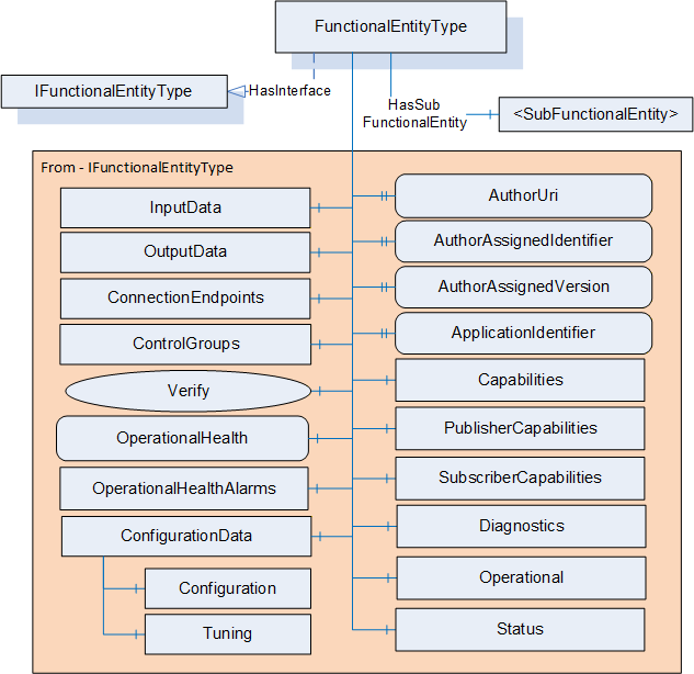
6.4.2 FunctionalEntityType definition
The FunctionalEntityType is formally defined in Table 41. Most of this ObjectType is obtained from the IFunctionalEntityType Interface (see 7.2). The description of the components and properties in a FunctionalEntityType is in this clause; the IFunctionalEntityType only references this clause. For examples of extending FunctionalEntityType or utilising it in an existing model, see Annex B. Annex C provides a description of how to apply SafetyData to FunctionalEntities.
| Attribute | Value | ||||
| BrowseName | 3:FunctionalEntityType | ||||
| IsAbstract | False | ||||
| References |
Node
Class | BrowseName | DataType | TypeDefinition | Other |
|---|---|---|---|---|---|
| Subtype of the 0:BaseObjectType defined in OPC 10000-5 | |||||
| 0:HasInterface | ObjectType | 3:IFunctionalEntityType | |||
| Applied from IFunctionalEntityType | |||||
|---|---|---|---|---|---|
| 0:HasProperty | Variable | 3:AuthorUri | 0:UriString | 0:PropertyType | O |
| 0:HasProperty | Variable | 3:AuthorAssignedIdentifier | 0:String | 0:PropertyType | O |
| 0:HasProperty | Variable | 3:AuthorAssignedVersion | 3:FxVersion | 0:PropertyType | O |
| 0:HasProperty | Variable | 3:ApplicationIdentifier | 3:ApplicationIdentifierDataType[] | 0:PropertyType | O |
| 0:HasComponent | Method | 3:Verify | Defined in 6.4.3 | O | |
| 0:HasComponent | Object | 3:InputData | 3:InputsFolderType | O | |
| 0:HasComponent | Object | 3:OutputData | 3:OutputsFolderType | O | |
| 0:HasComponent | Object | 3:ConfigurationData | 3:ConfigurationDataFolderType | O | |
| 0:HasComponent | Object | 3:Capabilities | 3:FunctionalEntityCapabilitiesType | O | |
| 0:HasComponent | Object | 3:PublisherCapabilities | 3:PublisherCapabilitiesType | O | |
| 0:HasComponent | Object | 3:SubscriberCapabilities | 3:SubscriberCapabilitiesType | O | |
| 0:HasComponent | Object | 3:ConnectionEndpoints | 3:ConnectionEndpointsFolderType | O | |
| 0:HasComponent | Object | 3:ControlGroups | 3:ControlGroupsFolderType | O | |
| 0:HasComponent | Variable | 3:OperationalHealth | 3:OperationalHealthOptionSet | 0:BaseDataVariableType | O, RO |
| 0:HasComponent | Object | 3:OperationalHealthAlarms | 0:FolderType | O | |
| 0:HasComponent | Object | 5:Status | 5:FunctionalGroupType | O | |
| 0:HasComponent | Object | 5:Diagnostics | 5:FunctionalGroupType | O | |
| 0:HasComponent | Object | 5:Operational | 5:FunctionalGroupType | O | |
| 3:HasSubFunctionalEntity | Object | 3:<SubFunctionalEntity> | 3:FunctionalEntityType | OP | |
| ConformanceUnits | |||||
|---|---|---|---|---|---|
| UAFX FunctionalEntity Base |
The components of the FunctionalEntityType have additional subcomponents, which are defined in Table 42.
| BrowsePath | References | NodeClass | BrowseName | DataType | TypeDefinition | Others |
| 3:ConfigurationData | 0:Organizes | Object | 5:Configuration | 5:FunctionalGroupType | O | |
| 3:ConfigurationData | 0:Organizes | Object | 5:Tuning | 5:FunctionalGroupType | O | |
| 5:Diagnostics | 0:HasComponent | Variable | 3:OperationalConnectionCount | 0:UInt32 | 0:BaseDataVariableType | O |
| 5:Diagnostics | 0:HasComponent | Variable | 3:ExistingConnectionCount | 0:UInt32 | 0:BaseDataVariableType | O |
| 5:Diagnostics | 0:HasComponent | Variable | 3:ErrorConnectionCount | 0:UInt32 | 0:BaseDataVariableType | O |
| 5:Diagnostics | 0:HasComponent | Variable | 3:FailedConnectionCount | 0:UInt32 | 0:BaseDataVariableType | O |
| 5:Diagnostics | 0:HasComponent | Variable | 3:CleanedUpConnectionCount | 0:UInt32 | 0:BaseDataVariableType | O |
| 5:Diagnostics | 0:HasComponent | Variable | 3:TotalEstablishAttemptsCount | 0:UInt32 | 0:BaseDataVariableType | O |
| 5:Diagnostics | 0:HasComponent | Variable | 3:FailedEstablishAttemptsCount | 0:UInt32 | 0:BaseDataVariableType | O |
| 5:Diagnostics | 0:HasComponent | Variable | 3:FailedVerificationCount | 0:UInt32 | 0:BaseDataVariableType | O |
The FunctionalEntityType is a base ObjectType. It is expected that companion specifications or vendors will define subtypes of FunctionalEntityType. Subtypes will define additional Variables that would exist in InputData, OutputData and ConfigurationData. The subtypes might also add Objects and Methods or define nested FunctionalEntityType instances. In addition, the information in the FunctionalEntityType may be directly used in an existing ObjectType, either via the AddIn concept or the Interface concept defined in OPC 10000-3. For an illustration of how this can be accomplished, see B.3.
The optional AuthorUri is a string that is a URI that resolves to the website of the company responsible for this FunctionalEntity.
The optional AuthorAssignedIdentifier provides a unique code used to identify the author-defined type of this FunctionalEntity. This Property is maintained by the author. The semantic of the AuthorAssignedIdentifier is author-specific.
The optional AuthorAssignedVersion provides the version of this FunctionalEntity. The semantic of the AuthorAssignedVersion is author-specific. This identifier is provided to allow additional information beyond what the AuthorAssignedIdentifier provides. For example, some authors might have more than one version of the motor controller model or the PID controller algorithm.
The optional ApplicationIdentifier – provides application information consisting of two properties: a localised Name that is intended to be human-readable and a unique identifier that is intended to be machine-readable. For a definition of the ApplicationIdentifierDataType, see 10.3. The ApplicationIdentifier shall be used as follows:
Name provides the name of the application in which this FunctionalEntity is used. The name is given by the system integrator, manufacturer or end-user that created the application.
UniqueIdentifier provides a unique identifier for the application in which FunctionalEntity is used. UniqueIdentifier is maintained by the creator of the identifier. This field is of ApplicationId DataType to allow the creator to create any type of identifier. An ApplicationId DataType allows the field to contain a string, integer, GUID, or ByteString. It is up to the creator of the identifier to choose which of these types is used.
The optional ApplicationIdentifier is specified as an array since it may indicate multiple levels of application and thus have multiple values. For example, the product vendor of an advanced alarm control creates a FunctionalEntity and assigns to it an identifier. A system integrator customises it with settings for boiler alarming and assigns an additional identifier. The end-user may further deploy an instance of the configured FunctionalEntity on “Boiler #5” and provide an additional identifier.
The optional InputData provides a grouping of information in this FunctionalEntity. It provides a reference to all data that this FunctionalEntity can use as input to its processing. The InputsFolderType is defined in 6.4.4.
The optional OutputData provides a grouping of information in this FunctionalEntity. It provides a reference to all data that this FunctionalEntity can use as output from its processing. The OutputsFolderType is defined in 6.4.5.
The optional ConfigurationData provides a grouping of information in this FunctionalEntity into logical groupings that are considered configuration information (for additional information, see 5.4). The ConfigurationDataFolderType is defined in 6.4.6.
The ConfigurationData Folder may also contain two FunctionalGroups (Configuration or Tuning) to further organise configuration information.
The optional Configuration FunctionalGroup contains Variables representing the configuration items of the FunctionalEntity (see OPC 10000-100 Recommended FunctionalGroup BrowseNames).
The optional Tuning FunctionalGroup contains Variables that can be used to optimise the behaviour of the FunctionalEntity (see OPC 10000-100 Recommended FunctionalGroup BrowseNames).
The optional Capabilities is a FunctionalEntityCapabilitiesType Folder that describes the functionality provided by a FunctionalEntity (see 6.4.7).
The optional PublisherCapabilities provide the Publisher capabilities associated with this FunctionalEntity. They also apply to all sub-FunctionalEntities of this FunctionalEntity. The PublisherCapabilities for the FunctionalEntity shall describe additional restrictions of the PublisherCapabilities defined in the AutomationComponent. It can also be further restricted by the PublisherCapabilities provided in OutputData (see 6.4.5) or a sub-FunctionalEntity. The restrictions for a sub-FunctionalEntity only apply if the Connection is established with the sub-FunctionalEntity or if OutputData defined in the sub-FunctionalEntity are part of the Connection. If a Connection utilises data from multiple sub-FunctionalEntities and the requested settings do not meet the PublisherCapabilities of all utilised sub-FunctionalEntities, a Server shall report an error (Bad_ConfigurationError). If an entry is an empty array, then it shall not change the settings defined in the AutomationComponent (or FunctionalEntity if defined in a sub-FunctionalEntity).
The optional SubscriberCapabilities provide the Subscriber capabilities associated with this FunctionalEntity. They also apply to all sub-FunctionalEntities of this FunctionalEntity. The SubscriberCapabilities for the FunctionalEntity shall describe additional restrictions of the SubscriberCapabilities defined in the AutomationComponent. It can also be further restricted by the SubscriberCapabilities provided in InputData (see 6.4.4) or a sub-FunctionalEntity. The restrictions for a sub-FunctionalEntity only apply if the Connection is established with the sub-FunctionalEntity or if InputData defined in the sub-FunctionalEntity are part of the Connection. If a Connection utilises data from multiple sub-FunctionalEntities and the requested settings do not meet the SubscriberCapabilities of all utilised sub-FunctionalEntities, a Server shall report an error (Bad_ConfigurationError).. If an entry is an empty array, then it shall not change the settings defined in the AutomationComponent (or FunctionalEntity if defined in a sub-FunctionalEntity).
The ConnectionEndpoints Folder provides a container for all Connection-related information that this FunctionalEntity might contain. For details on the ConnectionEndpointsFolderType, see 6.4.8. For details on the ConnectionEndpointType that this Folder contains, see 6.6. If the FunctionalEntity does not expose ConnectionEndpoints, the Folder may be missing.
The ControlGroups Folder provides a container for all ControlGroupType instances this FunctionalEntity might contain. For the concepts, see 5.3. For details on the ControlGroupsFolderType, see 6.4.9. For details on the ControlGroupType that this Folder contains, see 6.5.
The optional OperationalHealth indicates the operational health of the FunctionalEntity. It aggregates the health of its SubFunctionalEntities and the health of ConnectionEndpoints. For the definition of the OperationalHealthOptionSet, see 10.34.
The aggregation rules are defined as follows:
SubOperationalWarning is set to TRUE if at least one SubFunctionalEntity has OperationalWarning or SubOperationalWarning set to TRUE.
SubOperationalError is set to TRUE if at least one SubFunctionalEntity has OperationalError or SubOperationalError set to TRUE.
The lower 16 bits of OperationalHealth are set to the result of a logical OR of CommHealth in the ConnectionEndpoints Folder of the FunctionalEntity, and the lower 16 bits of the OperationalHealth of all SubFunctionalEntities.
All top-level FunctionalEntities shall implement OperationalHealth. The OperationalHealth of the top-level FunctionalEntities is aggregated into the AggregatedOperationalHealth (see 9.1.2) Variable of the AggregatedHealth Variable in the AutomationComponent (see 6.2.2).
The optional OperationalHealthAlarms Folder shall be restricted to hold only instances of Alarms. No UAFX-specific Alarms are defined in this release, but base OPC UA Alarms can be used. In future versions of this document, UAFX-specific Alarms will be defined.
The Operational FunctionalGroup contains Variables and Methods useful during normal operation, like process data (see OPC 10000-100 Recommended FunctionalGroup BrowseNames).
The Status FunctionalGroup contains Variables which describe the general health of the FunctionalEntity (see OPC 10000-100 Recommended FunctionalGroup BrowseNames).
The Diagnostics FunctionalGroup contains Variables and Methods for diagnostics. For UAFX, this includes diagnostics defined by UAFX (see OPC 10000-100 Recommended FunctionalGroup BrowseNames).
The optional <SubFunctionalEntity> allows for the nesting of FunctionalEntities. A FunctionalEntity can have any number of SubFunctionalEntities. SubFunctionalEntities are identified by the HasSubFunctionalEntity ReferenceType. They may be of FunctionalEntityType or another ObjectType that implements the IFunctionalEntityType Interface.
The OperationalConnectionCount provides the number of current ConnectionEndpoints with a Status of Operational in this FunctionalEntity.
The ExistingConnectionCount provides the number of ConnectionEndpoints that currently exist in this FunctionalEntity.
The ErrorConnectionCount provides the number of current ConnectionEndpoints with a Status of Error in this FunctionalEntity.
The FailedConnectionCount provides the number of transitions to the Error state for any ConnectionEndpoint in this FunctionalEntity.
The CleanedUpConnectionCount provides the number of ConnectionEndpoints that have been removed due to the expiration of the CleanupTimeout in this FunctionalEntity.
The TotalEstablishAttemptsCount provides the total number of attempts to create a ConnectionEndpoint that failed or succeeded in this FunctionalEntity.
The FailedEstablishAttemptsCount provides the total number of attempts to create a ConnectionEndpoint that failed due to an error in this FunctionalEntity.
The FailedVerificationCount provides the number of calls to Verify that returned a bad StatusCode in this FunctionalEntity.
6.4.3 Verify method
The Verify Method allows a Client to verify whether a FunctionalEntity meets the expectation of system engineering (e.g., whether it is of the expected author, but also if it implements any optional Variables required by a Client application). It also supports verifying any Variables defined by the application. The Verify Method should process all provided NodeIdValuePairs, but it is also acceptable to stop processing on the first NodeIdValuePair that results in a Mismatch or NotSet.
The signature of this Method is specified below; the arguments are defined in Table 43.
Signature
	Verify (
	[in] 2:NodeIdValuePair[]				ExpectedVerificationVariables,
	[out] 2:FunctionalEntityVerificationResultEnum	VerificationResult,
	[out] 0:StatusCode[]				VerificationVariablesErrors
);| Argument | Description |
| ExpectedVerificationVariables | An array of NodeIdValuePair containing verification variables. NodeId shall be the NodeId of the node to verify, and for variables, the Value is its expected value. The following rules shall apply to the usage of NodeIdValuePair: If NodeId refers to variables of type array, it shall be verified that Value is a matching array unless ArrayIndex is provided. If the ArrayIndex is provided, then a non-array Value is provided and shall be checked against the corresponding index. If Value is null, it shall be verified that NodeId exists. If the NodeId references a FunctionalEntity ApplicationIdentifier, then its Name sub-element shall always be ignored; only its UniqueIdentifier shall be used. A Client may pass in any NodeId with a null Value to verify if the Node exists in the Server. The Node may be of any NodeClass, but only the NodeClass of Variable or VariableType can have a non-null value. |
| VerificationResult | The result of the verification; see 10.22 for a definition of the FunctionalEntityVerificationResultEnum. The following general rules apply to determine VerificationResult: All string-type variables shall be stripped of leading and trailing whitespaces before processing. The following specific rules shall apply to determine VerificationResult: NotSet: Shall be returned if verification is not possible due to invalid elements in ExpectedVerificationVariables. An element is invalid if a non-null Value in NodeIdValuePair is not of the same type as the implemented verification variable. If this value is set, VerificationVariablesErrors shall be populated. Match: Shall be returned if all variables in ExpectedVerificationVariables exist in the Server and their actual values are identical to the expected values (where Value in NodeIdValuePair is not null). Mismatch: Shall be returned if one or more variables in ExpectedVerificationVariables either do not exist in the Server or do not have the expected value (where Value in NodeIdValuePair is not null). If this value is set, VerificationVariablesErrors shall be populated. |
| VerificationVariablesErrors | An array of StatusCode corresponding to the ExpectedVerificationVariables input argument that indicates any errors (if VerificationResult equals NotSet) or detailed verification results (if VerificationResult equals Mismatch). If this array is populated, the length of this array shall match the length of ExpectedVerificationVariables. For possible values in this array, see Table 45. |
The Method result codes are formally defined in Table 44.
| Result Code | Description |
| Bad_InvalidArgument | ExpectedVerificationVariables is empty. |
| Uncertain | There was at least one error or warning for one of the Variables to be verified. VerificationVariablesErrors will contain additional information. |
The VerificationVariablesErrors StatusCodes are formally defined in Table 45.
| Result Code | Description |
| Bad_TypeMismatch | The value supplied for the verification variable (if non-null) is not of the same type as the implemented verification variable. |
| Bad_NodeIdInvalid | The NodeIdValuePair contains a NodeId with an invalid syntax in its key field. |
| Bad_NodeIdUnknown | The NodeIdValuePair contains a NodeId in its key field that does not exist in the Server. |
| Bad_OutOfRange | The value supplied for the verification variable is not equal to the actual value of the Variable (if non-null). This includes if an array index is provided and the supplied value is not a scalar, or if an index was provided that is out of bounds of the array. This also includes if the node type is not a Variable or VariableType and a value is provided. In all cases, the value does not match. |
| Bad_NothingToDo | The operation was skipped. Verification of this Variable was skipped because verification of preceding Variables already resulted in VerificationResult being set to Mismatch or NotSet. |
| Good | The verification for this Variable succeeded. |
The Verify Method representation in the AddressSpace is formally defined in Table 46.
| Attribute | Value | ||||
| BrowseName | 3:Verify | ||||
| References | Node Class | BrowseName | DataType | TypeDefinition | Other |
|---|---|---|---|---|---|
| 0:HasProperty | Variable | 0:InputArguments | 0:Argument[] | 0:PropertyType | M |
| 0:HasProperty | Variable | 0:OutputArguments | 0:Argument[] | 0:PropertyType | M |
| ConformanceUnits | |||||
|---|---|---|---|---|---|
| UAFX IFunctionalEntity Verify |
6.4.4 InputsFolderType
The InputsFolderType is a subtype of the FolderType defined in OPC 10000-5.
The InputsFolderType is formally defined in Table 47.
| Attribute | Value | ||||
| BrowseName | 3:InputsFolderType | ||||
| IsAbstract | False | ||||
| References | NodeClass | BrowseName | DataType | TypeDefinition | Other |
|---|---|---|---|---|---|
| Subtype of the 0:FolderType defined in OPC 10000-5 | |||||
| 0:HasComponent | Object | 3:SubscriberCapabilities | 3:SubscriberCapabilitiesType | O | |
| 3:HasInputGroup | Object | 3:<InputGroup> | 3:InputsFolderType | OP | |
| 0:HierarchicalReferences | Variable | 3:<InputVariable> | 0:BaseDataType | 0:BaseDataVariableType | OP |
| ConformanceUnits | |||||
|---|---|---|---|---|---|
| UAFX FunctionalEntity Base |
The InputsFolderType provides for the grouping of input variables. It shall be restricted to hold only Variables, SubscriberCapabilities or nested <InputGroup>. The InputsFolder may be empty.
The optional SubscriberCapabilities shall only be present on InputData of the FunctionalEntity. It provides the Subscriber capabilities associated with the InputData and describes additional restrictions of the SubscriberCapabilities defined in the FunctionalEntity or AutomationComponent. The restrictions for InputData only apply if the Connection is established with Variables referenced in InputData or any subfolders. If an entry is an empty array, then it shall not change the settings defined in the AutomationComponent, FunctionalEntity or if defined in a sub-FunctionalEntity.
<InputGroup> allows for the nesting of Folders. Nested instances can be used to create a structure of input groups.
<InputVariable> is a reference to input Variables in this FunctionalEntity. The Variables shall be Organized in this Folder, or the Folder shall reference the Variable via subtypes of the HasChild Reference (HasProperty, HasComponent or other subtypes). The BrowseNames of Variables in this Folder shall be unique within this Folder; the use of nested <InputGroup> can be used to help accomplish this.
When using PubSub for periodic data with a fixed layout, Strings, ByteStrings, and variable-size arrays can cause problems. Without a defined maximum size for the Variables in a data packet, the fixed size of the data packet cannot be calculated. If using PubSub periodic data with a fixed layout, then the following apply:
Any Variables that are included in this Folder that have a DataType of String shall include a MaxStringLength property.
Any Variables that are included in this Folder that have a DataType of ByteString shall include a MaxByteStringLength property.
It is also recommended that any arrays be defined to have fixed dimensions.
6.4.5 OutputsFolderType
The OutputsFolderType is a subtype of the FolderType defined in OPC 10000-5.
The OutputsFolderType is formally defined in Table 48.
| Attribute | Value | ||||
| BrowseName | 3:OutputsFolderType | ||||
| IsAbstract | False | ||||
| References |
Node
Class | BrowseName | DataType | TypeDefinition | Other |
|---|---|---|---|---|---|
| Subtype of the 0:FolderType defined in OPC 10000-5 | |||||
| 0:HasComponent | Object | 3:PublisherCapabilities | 3:PublisherCapabilitiesType | O | |
| 3:HasOutputGroup | Object | 3:<OutputGroup> | 3:OutputsFolderType | OP | |
| 0:HierarchicalReferences | Variable | 3:<OutputVariable> | 0:BaseDataType | 0:BaseDataVariableType | OP |
| ConformanceUnits | |||||
|---|---|---|---|---|---|
| UAFX FunctionalEntity Base |
The OutputsFolderType provides for the grouping of output variables. It shall be restricted to hold only Variables, PublisherCapabilities or nested <OutputGroup>. The OutputsFolder may be empty.
The optional PublisherCapabilities shall only be present on OutputData of the FunctionalEntity. It provides the Publisher capabilities associated with the OutputData and describes additional restrictions of the PublisherCapabilities defined in the FunctionalEntity or AutomationComponent. The restrictions for OutputData only apply if the Connection is established with Variables referenced in OutputData or any subfolders. If an entry is an empty array, then it shall not change the settings defined in the AutomationComponent, FunctionalEntity or if defined in a sub-FunctionalEntity.
<OutputGroup> allows for the nesting of Folders. Nested instances can be used to create a structure of output groups.
<OutputVariable> is a reference to output Variables in this FunctionalEntity. The Variables shall be Organized in this Folder, or the Folder shall reference the Variable via subtypes of the HasChild Reference (HasProperty, HasComponent or other subtypes). The BrowseNames of Variables in this Folder shall be unique within this Folder; the use of nested <OutputGroup> can be used to help accomplish this.
When using PubSub for periodic data with a fixed layout, Strings, ByteStrings, and variable-size arrays can cause problems. Without a defined maximum size for the Variables in a data packet, the fixed size of the data packet cannot be calculated. If using PubSub periodic data with a fixed layout, then the following apply:
Any Variables that are included in this Folder that have a DataType of String shall include a MaxStringLength property.
Any Variables that are included in this Folder that have a DataType of ByteString shall include a MaxByteStringLength property.
It is also recommended that any arrays be defined to have fixed dimensions.
6.4.6 ConfigurationDataFolderType
6.4.6.1 Overview
The ConfigurationDataFolderType is used to organise ConfigurationData Variables and provides the Methods for supporting the storage of Variables (see 5.4). A ConfigurationDataFolder may contain sub-Folders derived from FunctionalGroupType.
The ConfigurationDataFolderType is illustrated in Figure 25.
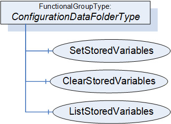
6.4.6.2 ConfigurationDataFolderType definition
The ConfigurationDataFolderType extends the FunctionalGroupType defined in OPC 10000-100.
The ConfigurationDataFolderType is formally defined in Table 49.
| Attribute | Value | ||||
| BrowseName | 3:ConfigurationDataFolderType | ||||
| IsAbstract | False | ||||
| References |
Node
Class | BrowseName | DataType | TypeDefinition | Other |
|---|---|---|---|---|---|
| Subtype of the 5:FunctionalGroupType defined in OPC 10000-100 | |||||
| 0:HierarchicalReferences | Variable | 3:<ConfigurationVariable> | 0:BaseDataType | 0:BaseDataVariableType | OP |
| 0:HasComponent | Method | 3:SetStoredVariables | Defined in 6.4.6.3 | O | |
| 0:HasComponent | Method | 3:ClearStoredVariables | Defined in 6.4.6.4 | O | |
| 0:HasComponent | Method | 3:ListStoredVariables | Defined in 6.4.6.5 | O | |
| ConformanceUnits | |||||
|---|---|---|---|---|---|
| UAFX FunctionalEntity Base |
<ConfigurationVariable> represents the optional configuration data. The Variables in this Folder shall be Organized in this Folder, or the Folder shall reference the Variables via subtypes of the HasChild Reference (HasProperty, HasComponent or other subtypes). The BrowseNames of Variables in this Folder shall be unique within this Folder. All Variables in this folder shall be configuration data.
The FunctionalGroupType, as defined in OPC 10000-100, includes the ability to have nested FunctionalGroups. It is expected that configuration data will often be organised into a tree of FunctionalGroups. This will also assist with the uniqueness requirement for BrowseNames.
The optional Methods SetStoredVariables, ClearStoredVariables, and ListStoredVariables allow for the maintenance of storage for configuration Variables. If storage is supported, SetStoredVariables, ClearStoredVariables, and ListStoredVariables shall be supported.
6.4.6.3 SetStoredVariables method
The optional SetStoredVariables Method allows a Client to store current values of configuration Variables for the FunctionalEntity and its SubFunctionalEntities.
The FunctionalEntity shall apply the stored values to the configuration variables after a power cycle.
The signature of this Method is specified below; the arguments are defined in Table 50.
Signature
	SetStoredVariables (
	  [in] 0:NodeId[]		VariablesToStore,
	  [out] 0:StatusCode[]	Results
);| Argument | Description |
| VariablesToStore | An array of NodeIds containing configuration data variables. NodeId shall be the NodeId of a configuration data variable belonging to ConfigurationData of this FunctionalEntity or one of its SubFunctionalEntities. |
| Results | An array of StatusCode corresponding to the VariablesToStore input argument that indicates any errors that occurred during the processing of VariablesToStore. If this array is populated, it has the same length as the VariablesToStore array. For possible values in this array, see Table 52. |
The possible Method result codes are formally defined in Table 51.
| Result Code | Description |
| Uncertain | There was at least one error while processing the Variables to be stored. Results will contain additional information. |
The Results StatusCodes are formally defined in Table 52.
| Result Code | Description |
| Bad_InvalidArgument | The NodeId is not a ConfigurationData Variable or does not belong to this FunctionalEntity or one of its SubFunctionalEntities. |
| Bad_NotSupported | The NodeId specifies a Variable that is non-volatile. |
| Bad_ResourceUnavailable | There are not enough resources to store this Variable. |
| Good | Storing this Variable succeeded. |
The SetStoredVariables Method representation in the AddressSpace is formally defined in Table 53.
| Attribute | Value | ||||
| BrowseName | 3:SetStoredVariables | ||||
| References | Node Class | BrowseName | DataType | TypeDefinition | Other |
|---|---|---|---|---|---|
| 0:HasProperty | Variable | 0:InputArguments | 0:Argument[] | 0:PropertyType | M |
| 0:HasProperty | Variable | 0:OutputArguments | 0:Argument[] | 0:PropertyType | M |
| ConformanceUnits | |||||
|---|---|---|---|---|---|
| UAFX ConfigurationDataFolder VariableStorage |
6.4.6.4 ClearStoredVariables Method
The optional ClearStoredVariables Method allows a Client to clear the Variable from the list of Variables that are to be restored.
The signature of this Method is specified below; the arguments are defined in Table 54.
Signature
	ClearStoredVariables (
	  [in] 0:NodeId[]		VariablesToClear,
	  [out] 0:StatusCode[]	Results
);| Argument | Description |
| VariablesToClear | An array of NodeId containing configuration data variables. |
| Results | An array of StatusCode corresponding to the VariablesToClear input argument that indicates any errors that occurred during the processing of VariablesToClear. If this array is populated, it has the same length as the VariablesToClear array. For possible values in this array, see Table 56. |
The possible Method result codes are formally defined in Table 55.
| Result Code | Description |
| Uncertain | There was at least one error while processing the Variables to be cleared. Results will contain additional information. |
The Results StatusCodes are formally defined in Table 56.
| Result Code | Description |
| Bad_InvalidArgument | The NodeId is not a ConfigurationData Variable or does not belong to this FunctionalEntity or one of its SubFunctionalEntities. |
| Bad_NotSupported | The NodeId specifies a Variable that is non-volatile or does not have storage for the Variable. |
| Good | Clearing the storage for this Variable succeeded. |
The ClearStoredVariables Method representation in the AddressSpace is formally defined in Table 57.
| Attribute | Value | ||||
| BrowseName | 3:ClearStoredVariables | ||||
| References | Node Class | BrowseName | DataType | TypeDefinition | Other |
|---|---|---|---|---|---|
| 0:HasProperty | Variable | 0:InputArguments | 0:Argument[] | 0:PropertyType | M |
| 0:HasProperty | Variable | 0:OutputArguments | 0:Argument[] | 0:PropertyType | M |
| ConformanceUnits | |||||
|---|---|---|---|---|---|
| UAFX ConfigurationDataFolder VariableStorage |
6.4.6.5 ListStoredVariables
The optional ListStoredVariables Method allows a Client to list the Variables that are currently in storage.
The signature of this Method is specified below; the arguments are defined in Table 58.
Signature
	ListStoredVariables (
	  [out] 2:NodeIdValuePair[]		StoredVariables
);| Argument | Description |
| StoredVariables | An array of NodeIdValuePair. Key indicates a Variable belonging to ConfigurationData of this FunctionalEntity or one of its SubFunctionalEntities. Value indicates the stored value. |
The ListStoredVariables Method representation in the AddressSpace is formally defined in Table 59.
| Attribute | Value | ||||
| BrowseName | 3:ListStoredVariables | ||||
| References | Node Class | BrowseName | DataType | TypeDefinition | Other |
|---|---|---|---|---|---|
| 0:HasProperty | Variable | 0:OutputArguments | 0:Argument[] | 0:PropertyType | M |
| ConformanceUnits | |||||
|---|---|---|---|---|---|
| UAFX ConfigurationDataFolder VariableStorage |
6.4.7 FunctionalEntityCapabilitiesType
The FunctionalEntityCapabilitiesType extends the FolderType defined in OPC 10000-5. It shall be restricted to holding only Variables that reflect the capabilities of the FunctionalEntity.
The FunctionalEntityCapabilitiesType is formally defined in Table 60.
| Attribute | Value | ||||
| BrowseName | 3:FunctionalEntityCapabilitiesType | ||||
| IsAbstract | False | ||||
| References |
Node
Class | BrowseName | DataType | TypeDefinition | Other |
|---|---|---|---|---|---|
| Subtype of the 0:FolderType defined in OPC 10000-5 | |||||
| 3:HasCapability | Variable | 3:<Capability> | 0:BaseDataType | 0:BaseDataVariableType | OP |
| 3:HasCapability | Variable | 3:FeedbackSignalRequired | 0:Boolean | 0:BaseDataVariableType | O |
| ConformanceUnits | |||||
|---|---|---|---|---|---|
| UAFX FunctionalEntity Base |
<Capability> - is an OptionalPlaceholder (defined in OPC 10000-3 ) to indicate that additional capabilities may be added by this document, by a companion specification or by a vendor application. These capabilities shall include a Description, and they follow all of the rules associated with an OptionalPlaceholder.
If the optional FeedbackSignalRequired is present and set to TRUE, the FunctionalEntity requires a feedback signal for all Connections. A feedback signal is represented by the reception of either data or a heartbeat. The following connection types (see 5.5.1) support feedback: bidirectional, unidirectional with heartbeat, unidirectional Subscriber, and autonomous Subscriber. If FeedbackSignalRequired is missing or set to FALSE, the connection types unidirectional Publisher and autonomous Publisher are also supported.
6.4.8 ConnectionEndpointsFolderType
The ConnectionEndpointsFolderType extends the FolderType defined in OPC 10000-5. It shall be restricted to hold only instances of ConnectionEndpointType or subtypes of ConnectionEndpointType. It may be empty.
The ConnectionEndpointsFolderType is formally defined in Table 61.
| Attribute | Value | ||||
| BrowseName | 3:ConnectionEndpointsFolderType | ||||
| IsAbstract | False | ||||
| References |
Node
Class | BrowseName | DataType | TypeDefinition | Other |
|---|---|---|---|---|---|
| Subtype of the 0:FolderType defined in OPC 10000-5 | |||||
| HasConnectionEndpoint | Object | 3:<ConnectionEndpoint> | 3:ConnectionEndpointType | OP | |
| 0:HasComponent | Variable | 3:CommHealth | 3:CommHealthOptionSet | 0:BaseDataVariableType | O, RO |
| ConformanceUnits | |||||
|---|---|---|---|---|---|
| UAFX FunctionalEntity Base |
The optional CommHealth aggregates the Status of all ConnectionEndpoints contained in the Folder. The aggregation rules are defined as follows:
If at least one ConnectionEndpoint established at this FunctionalEntity has its Status set to Error, the CommHealth CommError bit shall be set.
If at least one ConnectionEndpoint established at this FunctionalEntity has its Status set to Initial, the CommHealth CommInitial bit shall be set.
If at least one ConnectionEndpoint established at this FunctionalEntity has its Status set to PreOperational, the CommHealth CommPreOperational bit shall be set.
For the definition of the CommHealthOptionSet, see 10.9.
6.4.9 ControlGroupsFolderType
The ControlGroupsFolderType extends the FolderType defined in OPC 10000-5. It shall be restricted to holding only instances of ControlGroupType (see 6.5). The ControlGroupsFolder may be empty.
The ControlGroupsFolderType is formally defined in Table 62.
| Attribute | Value | ||||
| BrowseName | 3:ControlGroupsFolderType | ||||
| IsAbstract | False | ||||
| References |
Node
Class | BrowseName | DataType | TypeDefinition | Other |
|---|---|---|---|---|---|
| Subtype of the 0:FolderType defined in OPC 10000-5 | |||||
| 3:HasControlGroup | Object | 3:<ControlGroup> | 3:ControlGroupType | OP | |
| ConformanceUnits | |||||
|---|---|---|---|---|---|
| UAFX FunctionalEntity Base |
6.5 ControlGroupType
6.5.1 Overview
The ControlGroupType is used to manage the control of the functionality provided by a FunctionalEntity or part of it. ControlGroups are used when some part of a FunctionalEntity is to be “controlled” by another FunctionalEntity or application. ControlGroups can be used by an application to help understand how the Variables (inputs, outputs, configuration) and Methods are logically related to each other in the application. ControlGroups utilise the LockingServices defined in OPC 10000-100. The ControlGroupType is illustrated in Figure 26.
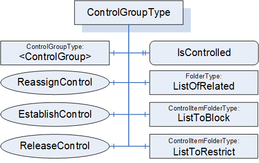
6.5.2 ControlGroupType definition
ControlGroups are part of the FunctionalEntity model and are independent of any communication model (Client Server, PubSub, etc.). A ControlGroup is used to identify the usage of parts of the FunctionalEntity. ControlGroups may result in a restriction on the grouped items. The restriction can include Objects (input and configuration Variables) and Method invocations. The restriction can block all changes to Variables or restrict changes to only the lock-owner (application or user). The lock-owner of the restrictions may be unrelated to the caller of the EstablishControl Method.
A Variable, Object, or Method may be referenced from more than one ControlGroup. Multiple ControlGroups might exist with different combinations.
ListToRestrict and ListToBlock each have their own instances of LockingServices. When a ControlGroup is assigned to a user or application, the Variables or Methods in ListToBlock or ListToRestrict are associated with that user or application (that user or application becomes the lock owner). The LockingServices exposed in ListToBlock and ListToRestrict (InitLock, RenewLock, ExitLock) can only be called by the lock-owner. An administrative user with appropriate rights may override a Lock and release it.
The ControlGroup also exposes EstablishControl, ReassignControl, and ReleaseControl Methods. EstablishControl will acquire the Lock for both ListToRestrict and ListToBlock. ReassignControl can be used to change the lock owner to a different user or application. ReleaseControl will release the Lock. A user or application different from the lock owner shall not be able to successfully call EstablishControl on another ControlGroup that references the same Variables or Methods in ListToBlock or ListToRestrict.
The EstablishConnections Method supports commands to establish control (EstablishControlCmd) and reassign control (ReassignControlCmd). The CloseConnections Method will release any Locks that may have been acquired as part of connection establishment. The functionality provided by EstablishConnections (ReassignControlCmd) and CloseConnections is the same as that provided by the individual Methods in the ControlGroup, except they operate on the Locks as the lock-owner. If a ControlGroup is assigned to a ConnectionEndpoint, only those having the rights to call EstablishConnections or CloseConnections can reassign or release control (i.e., the EstablishConnections and CloseConnections Methods act as the ConnectionEndpoint).
One or more Clients may call EstablishControl on separate ControlGroups that do not share any Variables or Methods (in ListToRestrict or ListToBlock). For examples of ControlGroups, see Annex D.3.
The FunctionalEntity may provide Variables in its InputData, OutputData and ConfigurationData Folders. A ControlGroup may include any combination of the input, output, and configuration Variables from the FunctionalEntity. A FunctionalEntity may provide information in InputData, OutputData and ConfigurationData that are not part of any ControlGroup.
ControlGroups are primarily used for locking, but they may also be used to merely provide a subset of FunctionalEntity configuration related to a specific described set of controls. The described grouping of functionality may be nested to allow further organisation of the functionality. For example, a simple PID may be modelled as a FunctionalEntity; it can be run in cascade mode where another FunctionalEntity provides the setpoint input, or it can allow an operator to enter setpoints via an HMI. In this case, two ControlGroups could be provided by the PID FunctionalEntity, and the choice of ControlGroup would lock the functionality into a specific mode. More complex FunctionalEntities might also restrict which ControlGroups are available based on configuration settings.
The ControlGroupType is formally defined in Table 63.
| Attribute | Value | ||||
| BrowseName | 3:ControlGroupType | ||||
| IsAbstract | False | ||||
| References |
Node
Class | BrowseName | DataType | TypeDefinition | Other |
|---|---|---|---|---|---|
| Subtype of the 0:BaseObjectType defined in OPC 10000-5 | |||||
| 0:HasComponent | Object | 3:ListToBlock | 3:ControlItemFolderType | M | |
| 0:HasComponent | Object | 3:ListToRestrict | 3:ControlItemFolderType | M | |
| 0:HasComponent | Object | 3:ListOfRelated | 0:FolderType | M | |
| 0:HasProperty | Variable | 3:IsControlled | 0:Boolean | 0:PropertyType | M |
| 0:HasComponent | Method | 3:EstablishControl | Defined in 6.5.3 | O | |
| 0:HasComponent | Method | 3:ReleaseControl | Defined in 6.5.4 | O | |
| 0:HasComponent | Method | 3:ReassignControl | Defined in 6.5.5 | O | |
| 0:HasComponent | Object | 3:<ControlGroup> | 3:ControlGroupType | OP | |
| ConformanceUnits | |||||
|---|---|---|---|---|---|
| UAFX IFunctionalEntity ControlGroups |
ListToBlock is a group of items that are to be blocked from any changes to Variables or executing Methods. This could be any Variables or Methods in the hierarchical structure of instances in the FunctionalEntity. Once an EstablishControl Call is made, the values of Variables in this list can no longer be modified, and Methods in this list can no longer be executed.
ListToRestrict is a group of items that are to be restricted to allow only the lock owner (see OPC 10000-100) to change Variables or execute Methods. This could be any Variables or Methods in the hierarchical structure of instances in the FunctionalEntity.
ListOfRelated is a group of items that are part of the ControlGroup that are not blocked or restricted (i.e., it is Objects, Variables, Methods).
A Variable, Method or Object shall not be included in more than one of the lists within a ControlGroup.
IsControlled is a flag that indicates if the ControlGroup is currently controlled. When this bit is set, the controlling entity can be determined by following the Controls Reference or by the information in the Lock Object (i.e., the Lock LockingClient) in either the ListToRestrict Folder or the ListToBlock Folder.
The optional EstablishControl Method invokes the LockingServices in both the ListToBlock and ListToRestrict groups. The Lock LockingClient is set to the LockContext parameter unless this parameter is a null String, in which case it is set to the ApplicationUri of the Client connection used to call this Method.
The optional ReassignControl Method will assign all active Locks in the ControlGroup to a different LockingClient.
The Locks can be assigned to a ConnectionEndpoint. In this case, the following applies:
All Locks automatically call the ExitLock Method if the associated ConnectionEndpoint is being removed.
The Lock LockingUser shall be set to “UAFX”.
The Locks are automatically renewed as long as the Status of the ConnectionEndpoint is different from Error.
A Controls Reference (see OPC 10000-23) shall be added with a SourceNode of the ConnectionEndpoint and the TargetNode of the ControlGroup.
If the lock is assigned to the Client connection, the Controls Reference (see OPC 10000-23) shall have a SourceNode of the Object associated with the Client connection (see OPC 10000-100) and a TargetNode of the ControlGroup.
The optional ReleaseControl Method calls the ExitLock Method on all established Locks and removes the Controls Reference. It also clears the IsControlled flag.
Calling the ExitLock Method on the Locks does not affect the IsControlled flag and associated Controls Reference; it will only release the Lock on the given group of items (ListToBlock, ListToRestrict).
The LockingServices provide a system-wide MaxInactiveLockTime, which a local MaxInactiveLockTime can overwrite in each lock Folder. If the CleanupTimeout is different for each Connection, then a local MaxInactiveLockTime should be specified and related to the ConnectionEndpoint CleanupTimeout. It is important to understand that this timeout will be used to timeout locks and thus must be larger than the CleanupTimeout if a lock is not to be removed before a Connection is removed. The system-wide MaxInactiveLockTime may be used for other applications or deployments of LockingServices, so care should be exercised if a local MaxInactiveLockTime is not used.
A ControlGroup can contain additional nested ControlGroups. The specified Methods of ControlGroupType shall not be applied to any nested ControlGroups.
6.5.3 EstablishControl method
This Method shall acquire Locks required by the ControlGroup in the ListToRestrict and ListToBlock. If acquiring any Lock fails, all Locks shall be released, and the appropriate LockStatus shall be returned. If all required Locks can be acquired, the Method shall set the IsControlled flag and create the Controls Reference.
It is recommended that this Method be restricted to Client connections that have the well-known Role ConnectionAdmin as defined in Clause 5.9.
EstablishControl shall set Lock LockingClient to the LockContext Argument.
The signature of this Method is specified below; the arguments are defined in Table 64.
Signature
	EstablishControl (
		[in] 0:String 	LockContext,
		[out] 0:Int32 	LockStatus
);| Argument | Description |
| LockContext | A string used to provide context information about the lock owner. It may be the NodeId (in string representation) of a ConnectionEndpoint or the ApplicationUri of a Client connection as provided in the CreateSession Service Call (see OPC 10000-4). If this parameter is a null string, it shall default to the ApplicationUri of the Client connection initiating this command. |
| LockStatus | 0 – OK -1 – E_AlreadyLocked – An element is already locked; this might be an entire Lock, or it might be a single variable in one of the lists. -2 – E_Invalid – the element cannot be locked |
The possible Method result codes are formally defined in Table 65.
| ResultCode | Description |
| Bad_UserAccessDenied | The caller is not allowed to establish control of the ControlGroup. |
The EstablishControl Method representation in the AddressSpace is formally defined in Table 66.
| Attribute | Value | ||||
| BrowseName | 3:EstablishControl | ||||
| References | Node Class | BrowseName | DataType | TypeDefinition | Other |
|---|---|---|---|---|---|
| 0:HasProperty | Variable | 0:InputArguments | Argument[] | 0:PropertyType | Mandatory |
| 0:HasProperty | Variable | 0:OutputArguments | Argument[] | 0:PropertyType | Mandatory |
| ConformanceUnits | |||||
|---|---|---|---|---|---|
| UAFX IFunctionalEntity ControlGroups |
6.5.4 ReleaseControl method
This Method Call shall release the ControlGroup and issue a Call to the Lock Objects in each Folder for the ExitLock Method (see OPC 10000-100). It shall create the appropriate parameters for the ExitLock Method. It shall remove the Controls Reference from the ControlGroup.
It is recommended that this Method be restricted to Client connections that have the well-known Role ConnectionAdmin as defined in Clause 5.9.
The signature of this Method is specified below.
Signature
	ReleaseControl (
	);
The possible Method result codes are formally defined in Table 67.
| Result Code | Description |
| Bad_UserAccessDenied | The caller is not allowed to release control on the ControlGroup. |
The ReleaseControl Method representation in the AddressSpace is formally defined in Table 68.
| Attribute | Value | ||||
| BrowseName | 3:ReleaseControl | ||||
| References | Node Class | BrowseName | DataType | TypeDefinition | Other |
|---|---|---|---|---|---|
| ConformanceUnits | |||||
| UAFX IFunctionalEntity ControlGroups | |||||
6.5.5 ReassignControl method
This Method shall reassign Locks required by the ControlGroup in the ListToRestrict and ListToBlock. It shall reassign the SourceNode of the Controls Reference (see OPC 10000-23) to the controlling entity as defined by the LockContext.
It shall set Lock LockingClient to the LockContext Argument.
It is recommended that this Method be restricted to Client connections that have the well-known Role ConnectionAdmin as defined in Clause 5.9.
The signature of this Method is specified below; the arguments are defined in Table 69.
Signature
	ReassignControl (
		[in] 0:String 	LockContext,
		[out] 0:Int32 	LockStatus
);| Argument | Description |
| LockContext | A string used to provide context information about the lock owner. It may be the NodeId (in string representation) of a ConnectionEndpoint or the ApplicationUri of a Client connection as provided in the CreateSession Service Call (see OPC 10000-4). It cannot be null. |
| LockStatus | 0 – OK -1 – E_NotLocked – the Object is not locked -2 – E_Invalid – the element cannot be reassigned |
The possible Method result codes are formally defined in Table 70.
| Result Code | Description |
| Bad_UserAccessDenied | The caller is not allowed to reassign control on the ControlGroup. |
| Bad_InvalidArgument | LockContext was null, invalid, or non-existent. |
The ReassignControl Method representation in the AddressSpace is formally defined in Table 71.
| Attribute | Value | ||||
| BrowseName | 3:ReassignControl | ||||
| References | Node Class | BrowseName | DataType | TypeDefinition | Other |
|---|---|---|---|---|---|
| 0:HasProperty | Variable | 0:InputArguments | 0:Argument[] | 0:PropertyType | M |
| 0:HasProperty | Variable | 0:OutputArguments | 0:Argument[] | 0:PropertyType | M |
| ConformanceUnits | |||||
|---|---|---|---|---|---|
| UAFX IFunctionalEntity ControlGroups |
6.5.6 ControlItemFolderType
The ControlItemFolderType is a subtype of the FunctionalGroupType.
The ControlItemFolderType is formally defined in Table 72.
| Attribute | Value | ||||
| BrowseName | 3:ControlItemFolderType | ||||
| IsAbstract | False | ||||
| References |
Node
Class | BrowseName | DataType | TypeDefinition | Other |
|---|---|---|---|---|---|
| Subtype of the 5:FunctionalGroupType defined in OPC 10000-100 | |||||
| 0:HasComponent | Object | 5:Lock | 5:LockingServicesType | M | |
| 0:HasProperty | Variable | 5:MaxInactiveLockTime | 0:Duration | 0:PropertyType | O |
| ConformanceUnits | |||||
|---|---|---|---|---|---|
| UAFX IFunctionalEntity ControlGroups |
The Lock is of LockingServicesType defined in Device Integration (see OPC 10000-100) and provides the basic locking functionality.
As described in OPC 10000-100, Locks will timeout after a MaxInactiveLockTime period unless there is activity as defined or unless the RenewLock Method is called on a Lock. An optional local MaxInactiveLockTime shall have precedence over the global MaxInactiveLockTime defined in the ServerCapabilities Object.
6.6 ConnectionEndpointType
6.6.1 Overview
A ConnectionEndpoint is used to represent an endpoint of a Connection between two FunctionalEntities for data exchange. It provides information about which InputVariables and/or OutputVariables are exchanged. ConnectionEndpoints reside in the ConnectionEndpoints Folder of a FunctionalEntity.
The ConnectionEndpointType is illustrated in Figure 27.
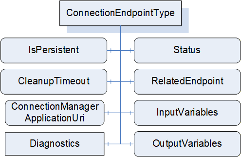
A ConnectionEndpoint further describes the link between Variables in the FunctionalEntityType and the communication model used for exchange. Communication models can be Client Server or PubSub. This type specifies the exchanged Variables and contains the status of the Connection. Subtypes of ConnectionEndpointType provide details specific to the utilised communication model and specify how the Connection status shall be determined for a given communication model.
Figure 28 illustrates a Connection between two FunctionalEntities and the use of PubSubConnectionEndpointType to represent the exchanged Variables, as well as corresponding References to the PubSub Information Model.
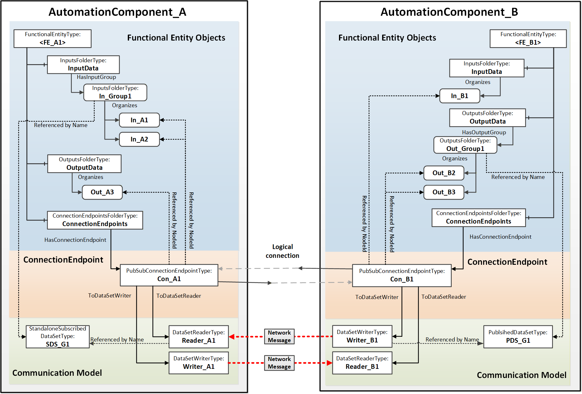
6.6.2 ConnectionEndpointType definition
This ObjectType is the abstract base type of all communication model-specific ConnectionEndpointTypes. It defines the elements and behaviour that are common to all ConnectionEndpointTypes. Additional communication model-specific subtypes are defined in subsequent clauses.
The ConnectionEndpointType is formally defined in Table 73Error! No bookmark name given..
| Attribute | Value | ||||
| BrowseName | 3:ConnectionEndpointType | ||||
| IsAbstract | True | ||||
| References |
Node
Class | BrowseName | DataType | TypeDefinition | Other |
|---|---|---|---|---|---|
| Subtype of the 0:BaseObjectType defined in OPC 10000-5 | |||||
| 0:HasComponent | Variable | 3:Status | 3:ConnectionEndpointStatusEnum | 0:BaseDataVariableType | M, RO |
| 0:HasComponent | Variable | 3:RelatedEndpoint | 2:RelatedEndpointDataType | 0:BaseDataVariableType | M |
| 0:HasComponent | Variable | 3:InputVariables | 0:NodeId[] | 0:BaseDataVariableType | O |
| 0:HasComponent | Variable | 3:OutputVariables | 0:NodeId[] | 0:BaseDataVariableType | O |
| 0:HasComponent | Variable | 3:IsPersistent | 0:Boolean | 0:BaseDataVariableType | M |
| 0:HasComponent | Variable | 3:CleanupTimeout | 0:Duration | 0:BaseDataVariableType | M |
| 0:HasComponent | Variable | 3:ConnectionManagerApplicationUri | 0:String | 0:BaseDataVariableType | O |
| 0:HasComponent | Object | 5:Diagnostics | 5:FunctionalGroupType | O | |
| 0:HasSubtype | ObjectType | 3:PubSubConnectionEndpointType | Defined in 6.6.3 | ||
| ConformanceUnits | |||||
|---|---|---|---|---|---|
| UAFX ConnectionEndpoint Base |
The components of the ConnectionEndpointType have additional subcomponents, which are defined in Table 74.
| BrowsePath | References | Node Class | BrowseName | DataType | TypeDefinition | Others |
| 5:Diagnostics | 0:HasComponent | Variable | 3:CreationTime | 0:DateTime | 0:BaseDataVariableType | O |
| 5:Diagnostics | 0:HasComponent | Variable | 3:ModificationTime | 0:DateTime | 0:BaseDataVariableType | O |
The Status describes the current status of a ConnectionEndpoint. This status is illustrated by the state machine in Figure 29. The Status values are defined in the ConnectionEndpointStatusEnum (see 10.17).
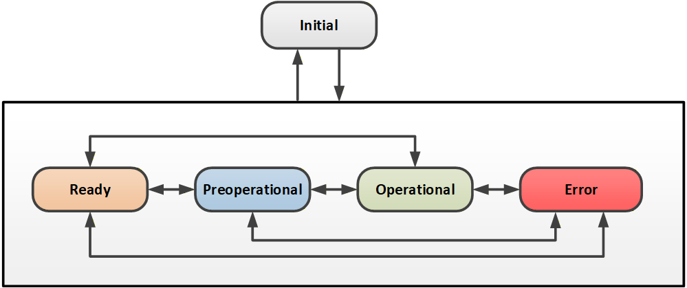
How Status is determined for a specific communication model is specified in the subtypes of ConnectionEndpointType.
The optional InputVariables indicate Variables that are to have their values updated by the communication model connected to the ConnectionEndpoint. All referenced Variables shall be in the InputData of the FunctionalEntity related to the ConnectionEndpoint or a SubFunctionalEntity of the FunctionalEntity. The referenced Variables may be a subset of the Variables referenced by InputData.
The optional OutputVariables reference Variables that are to be reported by the communication model connected to the ConnectionEndpoint. All referenced Variables shall be listed in the OutputData of the FunctionalEntity related to the ConnectionEndpoint or a SubFunctionalEntity of the FunctionalEntity. The referenced Variables may be a subset of the Variables referenced by OutputData.
The communication represented by the ConnectionEndpoint shall include all referenced InputVariables and OutputVariables.
A ConnectionEndpoint shall include at least one of the following:
1 or more InputVariables
1 or more OutputVariables
RelatedEndpoint points to the related ConnectionEndpoint (i.e., the other end of the Connection). The RelatedEndpointDataType is defined in 10.38. If the ConnectionEndpoint is not exposed in the Information Model of the related connection partner, RelatedEndpoint will specify the path to the connected FunctionalEntity.
IsPersistent indicates if the ConnectionEndpoint shall be persistent. Persistent ConnectionEndpoints shall be restored following a power cycle by the AutomationComponent. The restoration of a persistent ConnectionEndpoint shall include:
ConnectionEndpoint including references to ControlGroups and communication model Objects
Established control on related ControlGroups
Communication model Objects
An AutomationComponent indicates support for persistent Connections; see SupportsPersistence in 6.2.6.
Non-persistent ConnectionEndpoints following a power cycle behave as if the CloseConnections Method was called with Remove set to TRUE (see 6.2.5).
The CleanupTimeout defines a time delay period before a clean-up shall occur. The time delay period starts following a status change from Operational to any other Status. The time delay period is reset to its original value when the Status changes back to Operational. If the time delay period expires, this Connection shall be closed as if the CloseConnections Method was called with Remove set to TRUE (see 6.2.5), and if Auditing is supported, an Event of AuditConnectionCleanupEventType shall be generated. Any negative number indicates that the CleanupTimeout shall not be used, and no clean-up occurs. For a persistent ConnectionEndpoint, the CleanupTimeout shall be set to a negative number. A zero indicates immediate clean-up. CleanupTimeout processing may be disabled by a CloseConnections Call (see 6.2.5).
The ConnectionManagerApplicationUri can be used to identify the ConnectionManager that created this ConnectionEndpoint. The ConnectionManagerApplicationUri shall be set to the ApplicationUri in the ApplicationDescription associated with the Client connection from the ConnectionManager that established this Connection. If the ConnectionManager is local to this AutomationComponent (no Client connection), this shall be set to the ApplicationUri associated with the local ConnectionManager.
The CreationTime provides the timestamp associated with the creation of this ConnectionEndpoint.
The ModificationTime provides the timestamp associated with any modification of this ConnectionEndpoint. This timestamp shall be set on creation, enabling, and disabling.
6.6.3 PubSubConnectionEndpointType definition
PubSubConnectionEndpointType is a subtype of the ConnectionEndpointType. It extends the abstract ConnectionEndpointType with behaviour that is specific to the OPC UA PubSub communication model.
The PubSubConnectionEndpointType is illustrated in Figure 30.
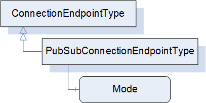
The PubSubConnectionEndpointType is formally defined in Table 75 and Table 76.
| Attribute | Value | ||||
| BrowseName | 3:PubSubConnectionEndpointType | ||||
| IsAbstract | False | ||||
| References |
Node
Class | BrowseName | DataType | TypeDefinition | Other |
|---|---|---|---|---|---|
| Subtype of the 3:ConnectionEndpointType | |||||
| HasComponent | Variable | 3:Mode | 2:PubSubConnectionEndpointModeEnum | 0:BaseDataVariableType | M |
| ConformanceUnits | |||||
|---|---|---|---|---|---|
| UAFX ConnectionEndpoint PubSub |
| SourceBrowsePath | Reference Type | IsForward | TargetBrowsePath | ||||||
| 3:ToDataSetReader | True |
| |||||||
| 3:ToDataSetWriter | True |
|
Mode defines the mode of the ConnectionEndpoint with respect to the Connection. The modes are formally defined in the PubSubConnectionEndpointModeEnum defined in Clause 10.42. They shall require the following references:
If Mode is PublisherSubscriber, a ToDataSetReader and a ToDataSetWriter Reference are required.
If Mode is Publisher, a ToDataSetWriter Reference is required; there shall be no ToDataSetReader set.
If Mode is Subscriber, a ToDataSetReader Reference is required; there shall be no ToDataSetWriter set.
A PubSubConnectionEndpoint shall have at most one ToDataSetReader and at most one ToDataSetWriter Reference (see 6.2.4.3.9.2).
If present, the ToDataSetReader Reference (see 11.21) shall point to the DataSetReader with which this ConnectionEndpoint is associated. It shall be present if the PubSubConnectionEndpoint references InputVariables or receives a heartbeat. The referenced DataSetReader shall be associated with a SubscribedDataSet having the subtype TargetVariablesType that contains all of the referenced ConnectionEndpoint InputVariables. If no InputVariables are referenced, the referenced DataSetReader shall be associated with a null DataSet (heartbeat).
If present, the ToDataSetWriter Reference (see 11.22) shall point to the DataSetWriter with which this ConnectionEndpoint is associated. It shall be present if the PubSubConnectionEndpoint references OutputVariables or publishes a heartbeat. The referenced DataSetWriter shall be associated with a PublishedDataSet having the subtype PublishedDataItemsType that contains all of the referenced ConnectionEndpoint OutputVariables. If no OutputVariables are referenced, the referenced DataSetWriter shall be associated with a null DataSet to publish the heartbeat.
The Status is determined based on the Status of the referenced DataSetReader and DataSetWriter. If a required Reference (see Mode) to a DataSetReader or DataSetWriter is missing, the Status shall be Initial.
For PubSubConnectionEndpoints with the Mode value of PublisherSubscriber, the Status shall be determined by the Status of the referenced DataSetReader and DataSetWriter as defined in Figure 31.
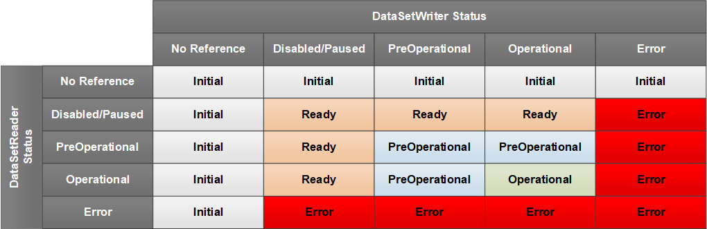
For PubSubConnectionEndpoints with Mode of Subscriber, the Status shall be determined by the Status of the referenced DataSetReader according to Figure 32.
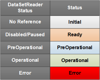
For PubSubConnectionEndpoints with Mode of Publisher, the Status shall be determined by the Status of the referenced DataSetWriter according to Figure 33.
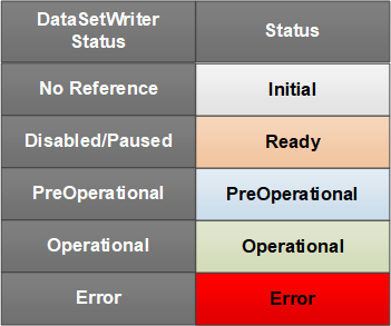
For the connection types autonomous publisher and autonomous subscriber (see 5.5.1), RelatedEndpoint Address shall be set to the Server address of the ConnectionEndpoint, the ConnectionEndpoint array shall be set to null or empty, and the ConnectionEndpointName to an empty String.
Annex E provides examples of PubSubConnectionEndpoints for the various types of Connections.
6.6.4 ClientServerConnectionEndpointType
The ClientServerConnectionEndpointType may be defined in a future version of this document.
6.7 ConnectionManagerType
6.7.1 Overview
Figure 34 illustrates the structure of the ConnectionManagerType. A ConnectionManager uses the configuration data stored in a ConnectionConfigurationSet (see 6.8) to establish Connections. Optional Methods are provided by ConnectionManagerType to allow Clients to manage editing and trigger the processing of Connections.
A ConnectionManager is represented by an instance of ConnectionManagerType; see 12 for details on its location in the UAFX Information Model.
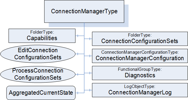
ConnectionConfigurationSets may be serialised into a file format as described in Annex F.
6.7.2 ConnectionManagerType definition
The ConnectionManagerType is formally defined in Table 77.
| Attribute | Value | ||||
| BrowseName | 4:ConnectionManagerType | ||||
| IsAbstract | False | ||||
| References |
Node
Class | BrowseName | DataType | TypeDefinition | Other |
|---|---|---|---|---|---|
| Subtype of the 0:BaseObjectType defined in OPC 10000-5 | |||||
| 0:HasComponent | Object | 4:ConnectionConfigurationSets | 0:FolderType | M | |
| 0:HasComponent | Object | 4:ConnectionManagerConfiguration | 4:ConnectionManagerConfigurationType | O | |
| 0:HasComponent | Method | 4:EditConnectionConfigurationSets | Defined in 6.7.4 | O | |
| 0:HasComponent | Method | 4:ProcessConnectionConfigurationSets | Defined in 6.7.5 | O | |
| 0:HasComponent | Object | 4:Capabilities | 4:ConnectionManagerCapabilitiesType | O | |
| 0:HasComponent | Variable | 4:AggregatedCurrentState | 0:Boolean | 0:BaseDataVariableType | O |
| 0:HasComponent | Object | 5:Diagnostics | 5:FunctionalGroupType | O | |
| 0:HasComponent | Object | 4:ConnectionManagerLog | 0:LogObjectType | O | |
| 0:GeneratesEvent | ObjectType | 4:CloseConnectionErrorEventType | |||
| 0:GeneratesEvent | ObjectType | 4:EstablishConnectionErrorEventType | |||
| ConformanceUnits | |||||
|---|---|---|---|---|---|
| UAFX ConnectionManager Base |
The components of the ConnectionManagerType have additional subcomponents, which are defined in Table 78.
| BrowsePath | References | Node Class | BrowseName | DataType | TypeDefinition | Others |
| 5:Diagnostics | 0:HasComponent | Variable | 4:EstablishCallCount | 0:UInt32 | 0:BaseDataVariableType | O |
| 5:Diagnostics | 0:HasComponent | Variable | 4:EstablishCallFailedCount | 0:UInt32 | 0:BaseDataVariableType | O |
| 5:Diagnostics | 0:HasComponent | Variable | 4:CloseCallCount | 0:UInt32 | 0:BaseDataVariableType | O |
| 5:Diagnostics | 0:HasComponent | Variable | 4:CloseCallFailedCount | 0:UInt32 | 0:BaseDataVariableType | O |
ConnectionConfigurationSets provides a Folder for the ConnectionConfigurationSets (defined in 6.8) that are exposed by this ConnectionManager. It shall be restricted to holding only instances of ConnectionConfigurationSetType, which provide the data required by a ConnectionManager to establish Connections. This Folder may also contain other Folders that can be used to organise the ConnectionConfigurationSets. The Folder may be empty. The string part of the BrowseName of ConnectionConfigurationSets shall be unique within a ConnectionConfigurationSets Folder.
ConnectionManagerConfiguration provides standardised mechanisms for adding, removing, or replacing ConnectionConfigurationSets (see F.1).
EditConnectionConfigurationSets provides a way to alter the Edit Property of one or more ConnectionConfigurationSets in a single Call.
ProcessConnectionConfigurationSets causes the ConnectionManager to manage Connections contained in one or more ConnectionConfigurationSets in a single Call (see 6.7.5). In addition, vendor-specific means may be used to trigger the processing of ConnectionConfigurationSets. All processing of ConnectionConfigurationSets shall follow the behaviour defined in 6.7.5.3.
Capabilities is a ConnectionManagerCapabilitiesType Folder that describes the functionality provided by a ConnectionManager (see 6.7.6).
AggregatedCurrentState shall be set to TRUE if one or more ConnectionConfigurationSets’ ConnectionConfigurationSetStateMachine is in State Error. This only indicates that the ConnectionManager encountered a problem in processing one or more of the ConnectionConfigurationSets; it does not indicate the status of the Connections.
ConnectionManagerLog exposes a LogObject for the ConnectionManager. The LogObject (see OPC 10000-26) can be accessed to obtain the log of activity related to the ConnectionManager. Standardised Events that can be used to trigger records for the LogObject are defined in 8.9 and 8.10. LogObject records can also be generated without the generation of an Event. If the LogObject is supported, the ConnectionManager shall generate records for all EstablishConnections calls, CloseConnections calls, and any related calls (see 13), including reporting of all errors. The reporting of all errors might result in multiple log records for a single call. For example, if there are multiple verification errors (e.g. Asset verification or FunctionalEntity verification), all would be logged. To facilitate tracking of LogRecords between the ConnectionManager and an AutomationComponent, the ConnectionManager shall provide the SpanContextDataType as part of the EstablishConnection Method Call to each AutomationComponent, as defined in OPC 10000-26.
EstablishCallCount diagnostics counter provides a count of the number of EstablishConnections calls issued by the ConnectionManager. This applies to local and remote calls.
EstablishCallFailedCount diagnostics counter provides a count of the number of EstablishConnections calls that failed (any command). This applies to local and remote calls.
CloseCallCount diagnostics counter provides a count of the number of CloseConnections calls issued by the ConnectionManager. This applies to local and remote calls.
CloseCallFailedCount diagnostics counter provides a count of the number of CloseConnections calls issued by the ConnectionManage that failed. This applies to local and remote calls.
The Diagnostics FunctionalGroup contains Variables and Methods for diagnostics (see OPC 10000-100 Recommended FunctionalGroup BrowseNames). For UAFX, this includes the defined diagnostic Variable in Table 78 – ConnectionManagerType additional subcomponentsTable 78.
6.7.3 ConnectionManager behaviour
6.7.3.1 Overview
The ConnectionManager performs the functionality described in this clause. This functionality may be invoked by a ConnectionManagerType-defined Method or by vendor-specific means.
6.7.3.2 Establishing Connections
To establish Connections defined in a ConnectionConfigurationSet, the ConnectionManager shall use the sequence of Calls illustrated in Figure 36 to the EstablishConnections Method on the involved AutomationComponents.
See Figure 35 for an illustration of the configuration information contained in the ConnectionConfigurationSet. The figure illustrates a single Connection. For further examples, please refer to Annex E.
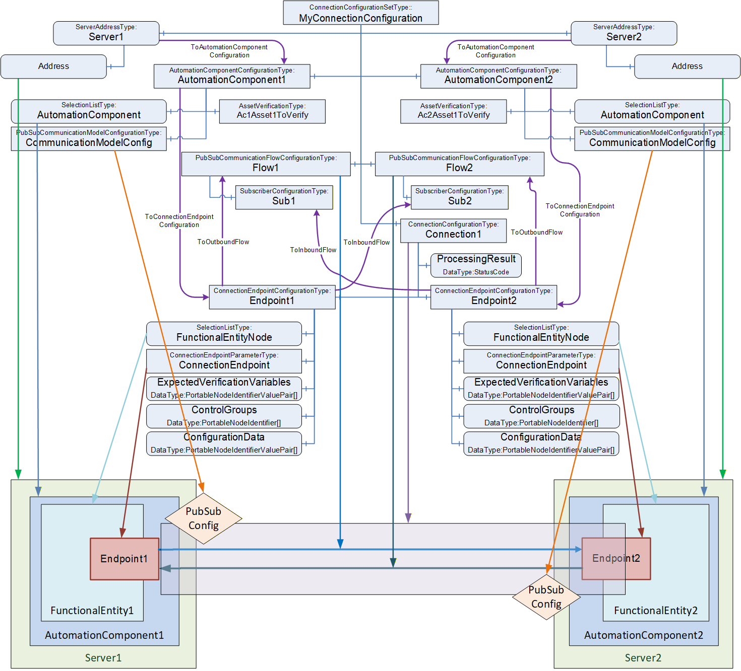
The EstablishConnections Method (see 6.2.4) is used to establish ConnectionEndpoints on an AutomationComponent.
The Method allows for the establishment of multiple Connections with a single Call. The number of Connections to be established with a single Call may be restricted by the addressed AutomationComponent as indicated by MaxConnectionsPerCall (see 6.2.6).
The Method provides several commands (see 10.23) to verify and create the individual Information Model Objects related to a Connection.
Figure 36 illustrates the sequence of commands to a single AutomationComponent when calling the EstablishConnections Method.
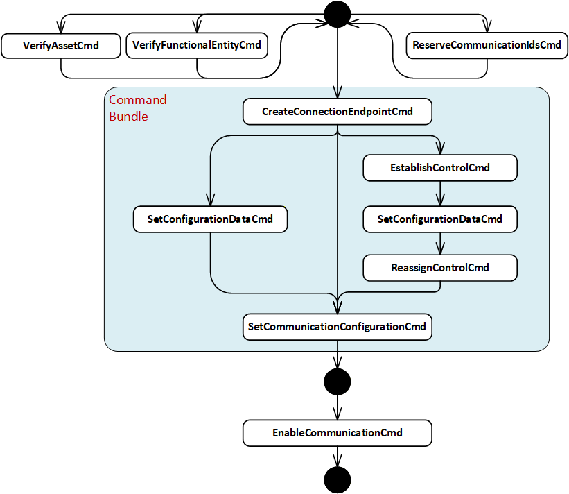
A ConnectionManager shall call the EstablishConnections Method on the AutomationComponents, passing in one or several commands to be executed together with their required arguments. A ConnectionManager may use one or multiple EstablishConnections Calls (see 6.2.4).
The ConnectionManager shall use the following commands in the following sequence: CreateConnectionEndpointCmd, EstablishControlCmd, SetConfigurationDataCmd, ReassignControlCmd, and SetCommunicationConfigurationCmd. The sequence may be built by having one EstablishConnections Call with the required commands (in this case, the mandated sequence is maintained by the AutomationComponent) or multiple subsequent EstablishConnections Calls by keeping the sequence of commands across the Calls (in this case, the mandated sequence is maintained by the ConnectionManager).
The ConnectionManager may use the following commands at any time and in any order: VerifyAssetCmd, VerifyFunctionalEntityCmd, ReserveCommunicationIdsCmd, and EnableCommunicationCmd.
A Client using the Methods exposed in the Information Model (e.g., VerifyAsset, ReassignControl) can invoke them in any order or at any time. The sequence is only mandated for the commands within the EstablishConnections Method.
The following applies to the usage of commands:
Commands may be omitted if not needed, e.g., if no ControlGroups are exposed by the AutomationComponent or used by the configuration in the ConnectionConfigurationSet, the commands EstablishControlCmd and ReassignControlCmd can be omitted.
Method Calls are subject to certain limits defined by OPC UA and provided by a Server (e.g., MaxMessageSize, MaxByteStringLength, etc.). Therefore, it might be necessary to issue commands in consecutive EstablishConnections Calls, e.g., to apply large configuration data, multiple Calls with SetConfigurationDataCmd can be required.
If AutomationComponentConfiguration CommandBundleRequired is set to TRUE, the ConnectionManager shall issue all required bundled commands in a single Call (see 6.2.4.3.1).
It is recommended that the ConnectionManager issue all required commands in a single Call.
It is recommended that a ConnectionManager performs operations in parallel when establishing multiple Connections between multiple AutomationComponents.
If Auditing is supported, the ConnectionManager shall generate an Event of AuditClientUpdateMethodResultEventType for all calls of the EstablishConnections Method and shall pass the AuditEventId as part of the Method invocation.
It is recommended that the ConnectionManager has the well-known Role ConnectionAdmin as defined in Clause 5.9.
Table 79 lists the commands and their required configuration information in the ConnectionConfigurationSetType Information Model.
| Command | Description | Relevant types from configuration model |
|---|---|---|
| VerifyAssetCmd | Verify that the Assets are the ones expected by system engineering. | The argument AssetVerifications that is passed for this command is constructed out of the AssetVerificationType instances in the AutomationComponentConfiguration. |
| VerifyFunctionalEntityCmd | Verify that the FunctionalEntity is the one expected by system engineering. | The argument ConnectionEndpointConfigurations ExpectedVerificationVariables that is passed for this command is constructed out of the ExpectedVerificationVariables contained in Endpoint1 or Endpoint2 Object in the instances of ConnectionConfigurationType. |
| ReserveCommunicationIdsCmd | Reserves identifiers for the communication configuration. | The argument ReserveCommunicationIds that is passed for this command is constructed out of the instance of CommunicationModelConfigurationType. |
| CreateConnectionEndpointCmd | Create a ConnectionEndpoint on the FunctionalEntity. Alternatively, use a preconfigured ConnectionEndpoint. | The argument ConnectionEndpointConfigurations ConnectionEndpoint that is passed for this command is constructed out of the Parameter Object in the ConnectionEndpoint Object in Endpoint1 or Endpoint2 Object in the instances of ConnectionConfigurationType. |
| EstablishControlCmd | Establish control of specific ControlGroups of the FunctionalEntity. | The argument ConnectionEndpointConfigurations ControlGroups that is passed for this command is constructed out of the ControlGroups Variable in Endpoint1 or Endpoint2 Object in the instances of ConnectionConfigurationType. |
| SetConfigurationDataCmd | Set ConfigurationData on the FunctionalEntity to adapt its behaviour as required (e.g., setting engineering units). | The argument ConnectionEndpointConfigurations ConfigurationData that is passed for this command is constructed out of the ConfigurationData Variable in Endpoint1 or Endpoint2 Object in the instances of ConnectionConfigurationType. |
| ReassignControlCmd | Reassigns the ControlGroups to be associated with a Connection. | The argument ConnectionEndpointConfigurations ControlGroups that is passed for this command is constructed out of the ControlGroups Variable in Endpoint1 or Endpoint2 Object in the instances of ConnectionConfigurationType. |
| SetCommunicationConfigurationCmd | Set communication configuration specific to the communication model utilised for data exchange (e.g., PubSub). | The argument CommunicationConfigurations that is passed for this command is constructed out of the instance of CommunicationModelConfigurationType. The argument ConnectionEndpointConfigurations CommunicationLinks is constructed out of the CommunicationLinks Variable in Endpoint1 or Endpoint2 Object in the instances of ConnectionConfigurationType. |
| EnableCommunicationCmd | Enable the communication model. | The argument ConnectionEndpointConfigurations ConnectionEndpoint that is passed for this command is constructed out of the ConnectionEndpoint Object in Endpoint1 or Endpoint2 Object in the instances of ConnectionConfigurationType. |
The ConnectionManager shall resolve identifier information contained in the ConnectionConfigurationSets to the arguments required for the EstablishConnections Call (see 13).
If any of the ConnectionEndpoints require SKS configuration, the ConnectionManager shall also call the SKS and add the appropriate configuration (SecurityGroups and/or PushTargets; see E.5 for examples).
If a configuration entry is null or empty, the corresponding command shall be skipped.
If EstablishConnections returns Uncertain, indicating an Abort of the Method (see 6.2.4.3.11) or if a fatal OPC UA communication error occurs, the ConnectionManager shall stop the establishing sequence and initiate a ProcessingToError transition in the ConnectionConfigurationSetStateMachine (see 6.9). If RollbackOnError is TRUE, the ConnectionManager shall call the Method CloseConnections for all ConnectionEndpoints established so far with Remove set to TRUE. If RollbackOnError is FALSE, no additional actions are performed by the ConnectionManager.
6.7.3.3 Closing Connections
To close Connections defined in a ConnectionConfigurationSet, a ConnectionManager shall use the CloseConnections Method on the AutomationComponents (see 6.2.5). A ConnectionManager may remove or disable the Connections.
If CloseConnections returns any error, the ConnectionManager shall complete closing all Connections in the ConnectionConfigurationSet and initiate a ProcessingToError transition in the ConnectionConfigurationSetStateMachine (see 6.9).
If any of the ConnectionEndpoints require SKS configuration and were removed, the ConnectionManager shall also remove the appropriate configuration from the SKS (SecurityGroups and/or PushTargets; see E.5 for examples).
6.7.4 EditConnectionConfigurationSets method
The EditConnectionConfigurationSets Method manages the editing of ConnectionConfigurationSets by a Client.
The Method shall set the Edit Property to TRUE for the requested ConnectionConfigurationSets. For ConnectionConfigurationSets which are not editable (indicated by the absence of the Property Edit), this Method shall return Bad_InvalidState. For the ConnectionConfigurationSets that allow editing, the Method shall also set the Lock to the Client Session associated with this Method Call. The Lock shall behave as described in OPC 10000-100, including the requirement to renew the Lock and to remove the Lock in the case of the Client Session exiting. If the Lock exits for any reason, the internal action on the ConnectionConfigurationSets shall be as if this Method was called with a DiscardUpdates Action. For ConnectionConfigurationSet, which is already in edit mode and locked to this Client Session, no action shall be performed on this ConnectionConfigurationSet, and a successful result will be returned.
If Action is CommitUpdates, the Method shall set the Property Edit to FALSE for all requested ConnectionConfigurationSets. The ConnectionManager shall only process committed updates. It shall reassign the Lock back to the ConnectionManager. If Version is supported, it shall always be incremented; for additional behaviour, see Version in 6.8.2. If the requesting Client does not own the Lock, the request is rejected with an error.
If Action is DiscardUpdates, the Method shall set the Property Edit to FALSE for all requested ConnectionConfigurationSets. The ConnectionManager shall discard the updates to the ConnectionConfigurationSet. It shall reassign the Lock back to the ConnectionManager. If the requesting Client does not own the Lock, the request is rejected with an error.
If a ConnectionConfigurationSet is called with Action set to either CommitUpdates or DiscardUpdates, but the Edit Property is FALSE, the Method shall ignore the Call for the ConnectionConfigurationSet.
The signature of this Method is specified below. The Method parameters are defined in Table 80.
Signature
	EditConnectionConfigurationSets (
		[in] 4:FxEditEnum		Action,
		[in] 0:NodeId[]		ConnectionConfigurationSets,
		[out] 0:StatusCode[]	Results
);| Argument | Description |
| Action | Indicates whether to allow editing, commit the updates to the ConnectionConfigurationSets or discard the updates. |
| ConnectionConfigurationSets | A list of NodeIds of ConnectionConfigurationSets to be edited. |
| Results | A list of StatusCode corresponding to the ConnectionConfigurationSets input argument. The length of this array shall match the length of the ConnectionConfigurationSets NodeId array. Clients may inspect this list to determine which ConnectionConfigurationSets were successfully updated and which failed. See Table 82 for possible Results values. |
The possible Method result codes are formally defined in Table 81.
| ResultCode | Description |
| Bad_UserAccessDenied | The caller is not allowed to invoke this Method. |
| Uncertain | There was at least one error or warning for one of the ConnectionConfigurationSets. Results will contain additional information. |
The possible Results StatusCodes are formally defined in Table 82. The Results array shall contain Good for any ConnectionConfigurationSet that was successfully updated.
| ResultCode | Description |
| Good | The operation succeeded. |
| Bad_NodeIdUnknown | The NodeId refers to a non-existent ConnectionConfigurationSet. |
| Bad_NodeIdInvalid | The syntax of the NodeId is not valid. |
| Bad_InvalidArgument | The NodeId for the requested ConnectionConfigurationSet was not a ConnectionConfigurationSet. |
| Bad_UserAccessDenied | The caller is not allowed to edit this ConnectionConfigurationSet. |
| Bad_InvalidState | The ConnectionConfigurationSet cannot be edited. The caller is not allowed to edit, commit, or discard updates since the ConnectionConfigurationSet is locked by a different Client. |
The EditConnectionConfigurationSets Method representation in the AddressSpace is formally defined in Table 83.
| Attribute | Value | ||||
| BrowseName | 4:EditConnectionConfigurationSets | ||||
| References | Node Class | BrowseName | DataType | TypeDefinition | Other |
|---|---|---|---|---|---|
| 0:HasProperty | Variable | 0:InputArguments | 0:Argument[] | 0:PropertyType | M |
| 0:HasProperty | Variable | 0:OutputArguments | 0:Argument[] | 0:PropertyType | M |
| 0:GeneratesEvent | ObjectType | 2:AuditUpdateMethodResultEventType | Defined in 8.4 | ||
| ConformanceUnits | |||||
|---|---|---|---|---|---|
| UAFX ConnectionManager EditConnectionConfigurationSets |
6.7.5 ProcessConnectionConfigurationSets method
6.7.5.1 Overview
The ProcessConnectionConfigurationSets Method causes the ConnectionManager to process the requested ConnectionConfigurationSets according to the specified Action:
ActionEstablishConnectionsEnabled, ActionEstablishConnectionsDisabled, and ActionEstablishConnections – establish all Connections contained in the ConnectionConfigurationSets (see 6.7.5.3)
ActionRemoveConnections – disable and remove all Connections contained in the ConnectionConfigurationSets (see 6.7.5.3.2)
ActionEnableConnections – enable the communication model for all Connections contained in the ConnectionConfigurationSets (see 6.7.5.3.3)
ActionDisableConnections – disable the communication model for all Connections contained in the ConnectionConfigurationSets (see 6.7.5.3.4)
6.7.5.2 ProcessConnectionConfigurationSets signature
The ProcessConnectionConfigurationSets Method shall initiate the ReadyToProcessing or ErrorToProcessing transition in the ConnectionConfigurationSetStateMachine (see 6.9) on all requested ConnectionConfigurationSets.
The Method triggers the processing and returns immediately. The result of processing is “returned” asynchronously by one of the ConnectionConfigurationSetEventType Events.
The signature of this Method is specified below; the Method arguments are defined in Table 84.
Signature
	ProcessConnectionConfigurationSets (
		 [in] 4:FxProcessEnum	Action,
		 [in] 0:NodeId[]		ConnectionConfigurationSets,
		 [out] 0:StatusCode[]	Results
);| Argument | Description |
| Action | The operation to be performed on the ConnectionConfigurationSets (see 10.25). |
| ConnectionConfigurationSets | A list of NodeIds of ConnectionConfigurationSets to be processed. |
| Results | The array of StatusCode corresponding to the ConnectionConfigurationSets input argument. The length of this array shall match the length of the ConnectionConfigurationSets NodeId array. Clients may inspect this list to determine the status of the individual Call to Trigger processing on each ConnectionConfigurationSet. For possible values for StatusCode, see Table 86. |
The possible Method result codes are formally defined in Table 85.
| ResultCode | Description |
| Bad_UserAccessDenied | The caller is not allowed to invoke this Method. |
| Bad_NotSupported | The requested Action is not supported. |
| Uncertain | There was at least one error or warning for one of the ConnectionConfigurationSets. Results will contain additional information. |
The possible Result StatusCodes are formally defined in Table 86.
| Result Code | Description |
| Good | Changing the State succeeded for the ConnectionConfigurationSet. |
| Bad_NodeIdInvalid | The syntax of the NodeId is not valid. |
| Bad_NodeIdUnknown | The NodeId refers to a node that does not exist in the Server address space. |
| Bad_InvalidArgument | The NodeId for the requested ConnectionConfigurationSet was not a ConnectionConfigurationSet. |
| Bad_UserAccessDenied | The caller is not allowed to trigger the processing of this ConnectionConfigurationSet. |
| Bad_InvalidState | The ConnectionConfigurationSet is in a State that does not allow it to be triggered for processing. |
The ProcessConnectionConfigurationSets Method representation in the AddressSpace is formally defined in Table 87.
| Attribute | Value | ||||
| BrowseName | 4:ProcessConnectionConfigurationSets | ||||
| References | Node Class | BrowseName | DataType | TypeDefinition | Other |
|---|---|---|---|---|---|
| 0:HasProperty | Variable | 0:InputArguments | 0:Argument[] | 0:PropertyType | M |
| 0:HasProperty | Variable | 0:OutputArguments | 0:Argument[] | 0:PropertyType | M |
| 0:GeneratesEvent | ObjectType | 2:AuditUpdateMethodResultEventType | Defined in 8.4 | ||
| ConformanceUnits | |||||
|---|---|---|---|---|---|
| UAFX ConnectionManager ProcessConnectionConfigurationSets |
6.7.5.3 ProcessConnectionConfigurationSets behaviour
6.7.5.3.1 ActionEstablishConnectionsEnabled / ActionEstablishConnectionsDisabled / ActionEstablishConnections
Calling ProcessConnectionConfigurationSets with Action set to ActionEstablishConnectionsEnabled, ActionEstablishConnectionsDisabled, or ActionEstablishConnections shall establish the Connections contained in the ConnectionConfigurationSets and their related communication model.
Establishing connections shall follow the behaviour specified in 6.7.3.2.
The ConnectionManager shall ensure the expected result of the requested Action as follows:
Calling ProcessConnectionConfigurationSets with Action set to ActionEstablishConnectionsEnabled shall establish all Connections contained in the ConnectionConfigurationSets with a disabled communication model and include EnableCommunicationCmd in the command sequence. A disabled communication model has Enabled flags set to FALSE for all DataSetReader and DataSetWriter configuration elements and to TRUE for all other elements (WriterGroup, ReaderGroup, PubSubConnection, and PublishSubscribe).
A disabled ClientServer communication model may be defined in a future version of this document.
Calling ProcessConnectionConfigurationSets with Action set to ActionEstablishConnectionsDisabled shall establish all Connections contained in the ConnectionConfigurationSets with a disabled communication model and omit EnableCommunicationCmd from the command sequence. A disabled communication model has Enabled flags set to FALSE for all DataSetReader and DataSetWriter configuration elements and to TRUE for all other elements (WriterGroup, ReaderGroup, PubSubConnection, and PublishSubscribe).
Calling ProcessConnectionConfigurationSets with Action set to ActionEstablishConnections shall establish all Connections contained in the ConnectionConfigurationSets with the communication model as configured by the engineering tool generating the communication model. The ConnectionManager shall apply the communication model as is, using the SetCommunicationConfigurationCmd and omit EnableCommunicationCmd from the command sequence. Depending on the state of the configuration elements (e.g., the value of the Enabled flag for PubSub configuration elements), parts of the communication model may be enabled, and others may be disabled. This allows, for example, a subset of the Connections to be enabled and the rest disabled. It is the responsibility of the engineering tool to configure the state of the configuration elements properly and consistently.
6.7.5.3.2 ActionRemoveConnections
Calling ProcessConnectionConfigurationSets with Action set to ActionRemoveConnections shall remove all Connections contained in the ConnectionConfigurationSets and their related communication model.
For each ConnectionConfigurationSet, the ConnectionManager shall call the CloseConnections Method (see 6.2.5) with Remove set to TRUE for all contained ConnectionEndpoints. See 6.7.3.3 for ConnectionManager behaviour.
6.7.5.3.3 ActionEnableConnections
Calling ProcessConnectionConfigurationSets with Action set to ActionEnableConnections shall enable all Connections contained in the ConnectionConfigurationSets.
For each ConnectionConfigurationSet, the ConnectionManager shall call the EstablishConnections Method, containing the EnableCommunicationCmd for all contained ConnectionEndpoints. See 6.7.3.2 for ConnectionManager behaviour.
6.7.5.3.4 ActionDisableConnections
Calling ProcessConnectionConfigurationSets with Action set to ActionDisableConnections shall disable all Connections contained in the ConnectionConfigurationSets.
For each ConnectionConfigurationSet, the ConnectionManager shall call the CloseConnections Method (see 6.2.5) with Remove set to FALSE for all contained ConnectionEndpoints. See 6.7.3.3 for ConnectionManager behaviour.
6.7.6 ConnectionManagerCapabilitiesType
The ConnectionManagerCapabilitiesType extends the FolderType defined in OPC 10000-5. It shall be restricted to holding only Variables that reflect the capabilities of the ConnectionManager.
The ConnectionManagerCapabilitiesType is formally defined in Table 88.
| Attribute | Value | ||||
| BrowseName | 4:ConnectionManagerCapabilitiesType | ||||
| IsAbstract | False | ||||
| References |
Node
Class | BrowseName | DataType | TypeDefinition | Other |
|---|---|---|---|---|---|
| Subtype of the 0:FolderType defined in OPC 10000-5 | |||||
| 4:HasCMCapability | Variable | 4:<Capability> | 0:BaseDataType | 0:BaseDataVariableType | OP |
| 4:HasCMCapability | Variable | 4:MaxConnectionConfigurationSets | 0:UInt32 | 0:BaseDataVariableType | O |
| 4:HasCMCapability | Variable | 4:MonitorsLocalConnectionEndpoints | 0:Boolean | 0:BaseDataVariableType | O |
| 4:HasCMCapability | Variable | 4:MonitorsAllConnectionEndpoints | 0:Boolean | 0:BaseDataVariableType | O |
| ConformanceUnits | |||||
|---|---|---|---|---|---|
| UAFX ConnectionManager Capabilities Base |
<Capability> - is an OptionalPlaceholder (defined in OPC 10000-3) to indicate that additional capabilities may be added by this document, a companion specification, or by a vendor at any time. These capabilities shall include a Description, and they follow all of the rules associated with an OptionalPlaceholder.
MaxConnectionConfigurationSets indicates the maximum number of ConnectionConfigurationSets that the ConnectionManager can support.
MonitorsLocalConnectionEndpoints, when true, describes the capability of the ConnectionManager Information Model to report the status of all the Connections created by this ConnectionManager that have a ConnectionEndpoint on this Server. If this capability is not provided, or false, the ConnectionManager Information Model does not report the current status of Connections.
NOTE In some cases, this status might include the status of the remote Connection.
MonitorsAllConnectionEndpoints, when true, describes the capability of the ConnectionManager Information Model to report status information for all ConnectionEndpoints of all Connections created by this ConnectionManager. This capability extends the MonitorsLocalConnectionEndpoints capability and shall not be provided if MonitorsLocalConnectionEndpoints is not provided.
6.8 ConnectionConfigurationSetType
6.8.1 Overview
The ConnectionConfigurationSetType is an ObjectType representing one or more Connection configurations. Connections are grouped in a set, for example, to allow sharing communication model configurations by multiple Connections; see 5.5.6.2.3 and 5.5.6.2.4 for appropriate use cases.
ConnectionConfigurationSets are generated and deployed to the ConnectionManager (see Figure 11, label 3). The ConnectionManager may expose the ConnectionConfigurationSets in its AddressSpace.
A ConnectionConfigurationSet exposes diagnostic information about the Connections as part of its Information Model. It also allows Connection configurations to be available for modification by standard Clients (see Figure 11, label 4), and it could provide an interface to trigger the processing of such Connection configurations.
A ConnectionConfigurationSet may only be modified by a standard Client as follows:
The SelectionListType (see OPC 10000-5) is used to indicate where support for modifications is required. This type allows the generator of the ConnectionConfigurationSet to provide a list of Selections and an optional description of them. If the optional RestrictToList is set to TRUE, a Client changing the Variable is restricted to the provided Selections. If set to FALSE or missing, a Client may change the Variable to any value, including one of the Selections. For example, the value of PublishingInterval may be restricted to the values 2 ms, 4 ms, and 8 ms by adding these values to Selections and setting RestrictToList to TRUE. If the value is fixed, the SelectionListType value shall be the fixed value, the Selections list shall be populated with the same fixed value, and the RestrictToList shall be TRUE.
Data that has been set to ReadWrite for specific users or in general. This can be determined by examining the AccessLevel and UserAccessLevel Attributes of the data.
With these mechanisms, the generator of the ConnectionConfigurationSet can specify and restrict the allowed changes.
For an overview of the ConnectionConfigurationSetType and its related types, see Figure 35. For examples, see Annex E.
The ConnectionConfigurationSetType is illustrated in Figure 37.
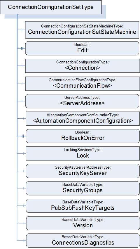
6.8.2 ConnectionConfigurationSetType definition
The ConnectionConfigurationSetType is formally defined in Table 89 and Table 90.
| Attribute | Value | ||||
| BrowseName | 4:ConnectionConfigurationSetType | ||||
| IsAbstract | False | ||||
| References |
Node
Class | BrowseName | DataType | TypeDefinition | Other |
|---|---|---|---|---|---|
| Subtype of the 0:BaseObjectType defined in OPC 10000-5 | |||||
| 0:HasComponent | Object | 4:ConnectionConfigurationSetStateMachine | 4:ConnectionConfigurationSetStateMachineType | M | |
| 0:HasProperty | Variable | 4:Edit | 0:Boolean | 0:PropertyType | O, RO |
| 4:HasConnectionConfiguration | Object | 4:<Connection> | 4:ConnectionConfigurationType | MP | |
| 4:HasCommunicationFlowConfiguration | Object | 4:<CommunicationFlow> | 4:CommunicationFlowConfigurationType | MP | |
| 4:HasServerAddress | Variable | 4:<ServerAddress> | 4:ServerAddressDataType | 4:ServerAddressType | MP |
| 4:HasAutomationComponentConfiguration | Object | 4:<AutomationComponentConfiguration> | 4:AutomationComponentConfigurationType | MP | |
| 0:HasProperty | Variable | 4:RollbackOnError | 0:Boolean | 0:PropertyType | M |
| 0:HasComponent | Object | 5:Lock | 5:LockingServicesType | M | |
| 0:HasComponent | Variable | 4:SecurityKeyServer | 4:SecurityKeyServerAddressDataType | 4:SecurityKeyServerAddressType | O |
| 0:HasComponent | Variable | 4:SecurityGroups | 0:SecurityGroupDataType[] | 0:BaseDataVariableType | O |
| 0:HasComponent | Variable | 4:PubSubKeyPushTargets | 0:PubSubKeyPushTargetDataType[] | 0:BaseDataVariableType | O |
| 0:HasComponent | Variable | 4:Version | 0:UInt32 | 0:BaseDataVariableType | O, RO |
| 0:HasComponent | Variable | 4:ConnectionsDiagnostics | 4:ConnectionDiagnosticsDataType[] | 0:BaseDataVariableType | O, RO |
| ConformanceUnits | |||||
|---|---|---|---|---|---|
| UAFX ConnectionManager Base |
| SourceBrowsePath | Reference Type | IsForward | TargetBrowsePath | ||
| 4:<ServerAddress> | 4:ToAutomationComponentConfiguration | True | 4:<AutomationComponentConfiguration> | ||
| 4:<AutomationComponentConfiguration> | 4:ToConnectionEndpointConfiguration | True |
| ||
| 4:<AutomationComponentConfiguration> | 4:ToConnectionEndpointConfiguration | True |
|
ConnectionConfigurationSetStateMachine contains the current State of this ConnectionConfigurationSet. See 6.9 for a formal definition of the state machine.
If Edit is present, the ConnectionConfigurationSet supports editing. If Edit is TRUE, the ConnectionConfigurationSet is currently being edited by a Client. See 6.7.4 on editing a ConnectionConfigurationSet.
<Connection> represents one or more instances of ConnectionConfigurationType, which defines Connection configurations to be established. For a formal definition, see 6.10.
<CommunicationFlow> represents one or more instances of CommunicationFlowConfigurationType, which defines communication model-specific configuration to apply to a Connection. For a formal definition, see 6.13. There may be fewer instances of this type than ConnectionConfigurations.
<ServerAddress> represents one or more instances of ServerAddressType, which defines addressing information for AutomationComponents. For a formal definition, see 9.2. There may be fewer instances of this type than ConnectionConfigurations.
<AutomationComponentConfiguration> represents one or more AutomationComponents. In addition, it holds the parameters used for Asset verification. For a formal definition, see 6.14.
RollbackOnError indicates the behaviour that should be followed when there is an error with Connection establishment. If this Property is TRUE and an error occurs during the Connection establishment sequence, establishing the set shall stop, and all established Connections that are part of this set shall be closed (see 6.7.3.2).
It is recommended that the system integrator Client use the well-known Role ConfigureAdmin, as defined in Clause 5.9, for accessing this Object. It is recommended that the modifiable content of the ConnectionConfigurationSet has the write privilege for the well-known Role ConfigureAdmin as defined in Clause 5.9.
Lock is an instance of LockingServicesType, defined in OPC 10000-100, which provides the basic locking functionality. A ConnectionConfigurationSet that is not in editable mode shall be locked to the ConnectionManager and blocked from any changes (the Client is set to the NodeId of the ConnectionManager, and the user is set to “CM”). A Client can call the EditConnectionConfigurationSets Method on a ConnectionManager to release the Lock from the ConnectionManager and assign it to the Client that issued the EditConnectionConfigurationSets Method Call (for additional details, see 6.7.4).
SecurityKeyServerAddress defines the location of the SKS to be used for PubSub security configuration of this ConnectionConfigurationSet. For a formal definition, see 9.3.
SecurityGroups and PubSubPushKeyTargets define the configuration information to be applied to the SKS for PubSub security configuration of the ConnectionConfigurationSet.
Version shall be a monotonically increasing number. It shall be incremented by 1 on each change to a given ConnectionConfigurationSet, no matter the source of the change. Its ServerTimestamp shall be set to the time of the change. When a ConnectionConfigurationSet is added or replaced (i.e., new NodeId), Version shall be set to 1. Changes could occur via the CloseAndUpdate Method defined in F.3.3, via the EditConnectionConfigurationSets Method, or via vendor-specific means.
ConnectionsDiagnostics provides an array of diagnostic information for Connections included in this ConnectionConfigurationSet. There shall be one element in this array for each <Connection> instance in the ConnectionConfigurationSet. The Name field of the ConnectionDiagnosticsType provides a linkage between an array element and a specific <Connection>. The value of this Variable shall be updated every time the ConnectionManager finishes processing the ConnectionConfigurationSet. If a ConnectionManager monitors ConnectionEndpoints, it shall also update the value when it acquires new information about the status of the Connections. See 10.19 and 10.20 for details on how to update the value.
The ToAutomationComponentConfiguration Reference is used to link a ServerAddress to AutomationComponentConfiguration (see 6.14). The ServerAddress provides the Connection information to address the referenced AutomationComponent.
The ToConnectionEndpointConfiguration Reference is used to link an AutomationComponentConfiguration to ConnectionEndpointConfigurations (see 6.11).
The ToOutboundFlow Reference is used to link a ConnectionEndpointConfiguration to a PubSubCommunicationFlowConfiguration (see 6.13.3). This Reference defines the PubSub-specific configuration to be used for the transmission of output data related to this ConnectionEndpoint. It shall be present if an outbound PubSub flow is configured.
The ToInboundFlow Reference is used to link a ConnectionEndpointConfiguration to a SubscriberConfiguration (see 6.13.3.3). This Reference defines the PubSub-specific configuration to be used for the reception of input data related to this ConnectionEndpoint. It shall be present if an inbound PubSub flow is configured.
A ConnectionEndpointConfiguration shall have at most one ToOutboundFlow and at most one ToInboundFlow Reference.
The References used to link a ConnectionEndpointConfiguration to Client Server-specific communication configuration will be defined in a later version of this document.
6.9 ConnectionConfigurationSetStateMachineType
6.9.1 Overview
A state machine is defined as a mechanism to coordinate actions executed internally (a ConnectionManager establishing Connections) that involve the processing of a ConnectionConfigurationSet. The States and Transitions that comprise the state machine are illustrated in Figure 38. Numbers in circles indicate the TransitionNumber of a transition.
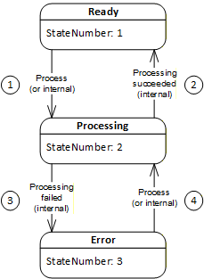
The transitions with TransitionNumber 1 and 4 (process) may also be triggered by a Client but are more typically triggered internally by a vendor-specific algorithm. The transitions with TransitionNumber 2 (processing succeeded) and 3 (processing failed) are only triggered internally on completion of Connection establishment processing.
A ConnectionConfigurationSetStateMachine may transition to Error for several reasons. Transient errors will be resolved by re-processing the ConnectionConfigurationSet. If the transient error has cleared, the state machine will transition to Ready; otherwise, it will return to Error. The error may be a permanent error that needs correction by the system integrator.
6.9.2 ConnectionConfigurationSetStateMachineType definition
The ConnectionConfigurationSetStateMachineType and the corresponding set of Methods (see ConnectionConfigurationSetType) and Events (subtypes of the ConnectionConfigurationSetEventType) are illustrated in Figure 39.
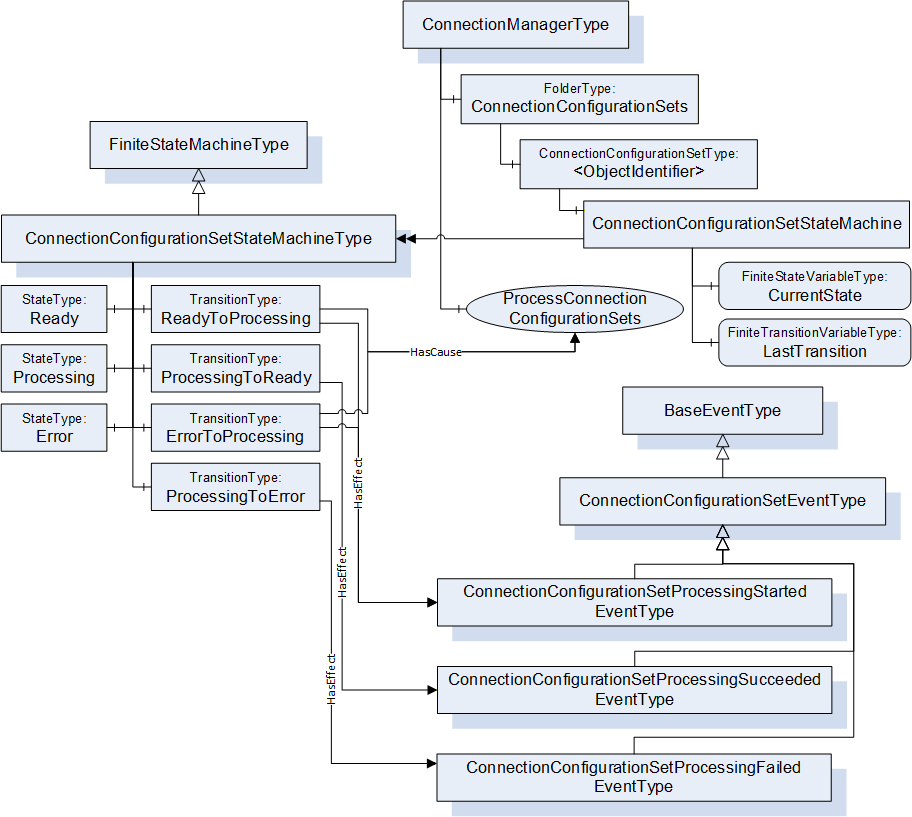
Methods and Events illustrated in Figure 39 are defined in subsequent clauses. The ConnectionConfigurationSetStateMachineType is formally defined in Table 91. StateType and TransitionType only exist in the type system; thus, they do not have a modelling rule.
| Attribute | Value | ||||
| BrowseName | 4:ConnectionConfigurationSetStateMachineType | ||||
| IsAbstract | False | ||||
| References |
Node
Class | BrowseName |
Data
Type | TypeDefinition | Other |
|---|---|---|---|---|---|
| Subtype of the 0:FiniteStateMachineType defined in OPC 10000-16 | |||||
| 0:HasComponent | Variable | 0:LastTransition | 0:LocalizedText | 0:FiniteTransitionVariableType | M |
| 0:HasComponent | Object | 4:Ready | 0:StateType | ||
| 0:HasComponent | Object | 4:Processing | 0:StateType | ||
| 0:HasComponent | Object | 4:Error | 0:StateType | ||
| 0:HasComponent | Object | 4:ReadyToProcessing | 0:TransitionType | ||
| 0:HasComponent | Object | 4:ProcessingToReady | 0:TransitionType | ||
| 0:HasComponent | Object | 4:ProcessingToError | 0:TransitionType | ||
| 0:HasComponent | Object | 4:ErrorToProcessing | 0:TransitionType | ||
| ConformanceUnits | |||||
|---|---|---|---|---|---|
| UAFX ConnectionManager Base |
The components of the ConnectionConfigurationSetStateMachineType have additional references, which are defined in Table 92.
| SourceBrowsePath | Reference Type | IsForward | TargetBrowsePath | ||
| 4:ReadyToProcessing | 0:ToState | True | 4:Processing | ||
| 0:FromState | True | 4:Ready | |||
| 0:HasCause | True |
| |||
| 0:HasEffect | True | 4:ConnectionConfigurationSetProcessingStartedEventType | |||
| 4:ProcessingToReady | 0:ToState | True | 4:Ready | ||
| 0:FromState | True | 4:Processing | |||
| 0:HasEffect | True | 4:ConnectionConfigurationSetProcessingSucceededEventType | |||
| 4:ProcessingToError | 0:ToState | True | 4:Error | ||
| 0:FromState | True | 4:Processing | |||
| 0:HasEffect | True | 4:ConnectionConfigurationSetProcessingFailedEventType | |||
| 4:ErrorToProcessing | 0:ToState | True | 4:Processing | ||
| 0:FromState | True | 4:Error | |||
| 0:HasCause | True |
| |||
| 0:HasEffect | True | 4:ConnectionConfigurationSetProcessingStartedEventType |
The component Variables of the ConnectionConfigurationSetStateMachineType have additional Attributes defined in Table 93.
| BrowsePath | Value Attribute | ||
| 1 | ||
| 2 | ||
| 3 | ||
| 1 | ||
| 2 | ||
| 3 | ||
| 4 |
Ready – A ConnectionConfigurationSet in this State may be processed by the ConnectionManager.
Processing – A ConnectionConfigurationSet in this State indicates that it is currently being processed by the ConnectionManager (i.e., Connections are being established). Internals of the processing executed in this State are described in 6.7.5.3.
Error – A ConnectionConfigurationSet in this State indicates an error has occurred during Processing.
ReadyToProcessing – This transition shall be initiated by the ProcessConnectionConfigurationSets Method Call. In addition, this state transition may also be initiated by vendor-specific means. While in State Processing, the ConnectionManager establishes or closes the Connections contained in the ConnectionConfigurationSet; for details, see 6.7.5.3.
ProcessingToReady – This transition shall be initiated if the ConnectionManager succeeds in processing all of the Connections contained in the ConnectionConfigurationSet.
ProcessingToError – This transition shall be initiated if the ConnectionManager fails the processing of any Connection contained in the ConnectionConfigurationSet.
Information about the success or failure of the establishment of specific Connections is provided by the ProcessingResult Property in ConnectionConfigurationType.
ErrorToProcessing – This transition shall be initiated by the ProcessConnectionConfigurationSets Method Call. In addition, this state transition may also be initiated by vendor-specific means.
6.10 ConnectionConfigurationType
6.10.1 Overview
The ConnectionConfigurationType ObjectType describes the configuration information needed to establish a single Connection contained in the ConnectionConfigurationSetType.
The ConnectionConfigurationType is illustrated in Figure 40.
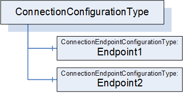
6.10.2 ConnectionConfigurationType definition
The ConnectionConfigurationType is formally defined in Table 94.
| Attribute | Value | ||||
| BrowseName | 4:ConnectionConfigurationType | ||||
| IsAbstract | False | ||||
| References |
Node
Class | BrowseName | DataType | TypeDefinition | Other |
|---|---|---|---|---|---|
| Subtype of the 0:BaseObjectType defined in OPC 10000-5 | |||||
| 0:HasComponent | Object | 4:Endpoint1 | 4:ConnectionEndpointConfigurationType | M | |
| 0:HasComponent | Object | 4:Endpoint2 | 4:ConnectionEndpointConfigurationType | O | |
| ConformanceUnits | |||||
|---|---|---|---|---|---|
| UAFX ConnectionManager Base |
Endpoint1 and the optional Endpoint2 hold the configuration information for the endpoints of the Connection. The ConnectionEndpointConfigurationType is defined in 6.11.
6.11 ConnectionEndpointConfigurationType
6.11.1 Overview
The ConnectionEndpointConfigurationType ObjectType holds the information for an endpoint of a Connection.
The ConnectionEndpointConfigurationType is illustrated in Figure 41.
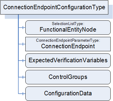
6.11.2 ConnectionEndpointConfigurationType definition
The ConnectionEndpointConfigurationType is formally defined in Table 95.
| Attribute | Value | ||||
| BrowseName | 4:ConnectionEndpointConfigurationType | ||||
| IsAbstract | False | ||||
| References |
Node
Class | BrowseName | DataType | TypeDefinition | Other |
|---|---|---|---|---|---|
| Subtype of the 0:BaseObjectType defined in OPC 10000-5 | |||||
| 0:HasComponent | Variable | 4:FunctionalEntityNode | 4:PortableNodeIdentifier | 0:SelectionListType | M |
| 0:HasComponent | Object | 4:ConnectionEndpoint | 4:ConnectionEndpointParameterType | M | |
| 0:HasComponent | Variable | 4:ExpectedVerificationVariables | 4:PortableNodeIdentifierValuePair[] | 0:BaseDataVariableType | O |
| 0:HasComponent | Variable | 4:ControlGroups | 4:PortableNodeIdentifier[] | 0:BaseDataVariableType | O |
| 0:HasComponent | Variable | 4:ConfigurationData | 4:PortableNodeIdentifierValuePair[] | 0:BaseDataVariableType | O |
| ConformanceUnits | |||||
|---|---|---|---|---|---|
| UAFX ConnectionManager Base |
FunctionalEntityNode specifies the identifier of the FunctionalEntity to configure for this Connection. If a PortableRelativePath is specified, the path shall be relative to FxRoot.
ConnectionEndpoint specifies the parameters for the ConnectionEndpoint to be used for the Connection.
ExpectedVerificationVariables, if present, specifies the variables to be verified. If a PortableRelativePath is specified as Key, the path shall be relative to FunctionalEntityNode.
ControlGroups, if present, specifies the ControlGroups to be controlled. If a PortableRelativePath is specified, the path shall be relative to FunctionalEntityNode.
6.12 ConnectionEndpointParameterType
6.12.1 Overview
The ConnectionEndpointParameterType ObjectType holds the parameters to create the ConnectionEndpoint of a Connection.
The ConnectionEndpointParameterType is illustrated in Figure 42.
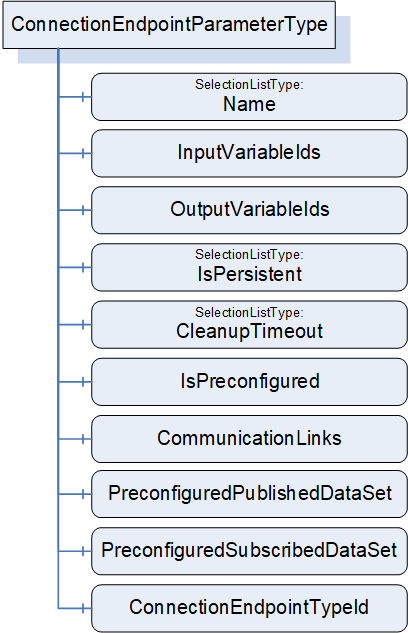
6.12.2 ConnectionEndpointParameterType definition
The ConnectionEndpointParameterType is formally defined in Table 96.
| Attribute | Value | ||||
| BrowseName | 4:ConnectionEndpointParameterType | ||||
| IsAbstract | False | ||||
| References |
Node
Class | BrowseName | DataType | TypeDefinition | Other |
|---|---|---|---|---|---|
| Subtype of the 0:BaseObjectType defined in OPC 10000-5 | |||||
| 0:HasComponent | Variable | 4:Name | 0:String | 0:SelectionListType | M |
| 0:HasComponent | Variable | 4:ConnectionEndpointTypeId | 0:PortableNodeId | 0:BaseDataVariableType | M |
| 0:HasComponent | Variable | 4:InputVariableIds | 4:PortableNodeIdentifier[] | 0:BaseDataVariableType | O |
| 0:HasComponent | Variable | 4:OutputVariableIds | 4:PortableNodeIdentifier[] | 0:BaseDataVariableType | O |
| 0:HasComponent | Variable | 4:IsPersistent | 0:Boolean | 0:SelectionListType | M |
| 0:HasComponent | Variable | 4:CleanupTimeout | 0:Duration | 0:SelectionListType | M |
| 0:HasComponent | Variable | 4:IsPreconfigured | 0:Boolean | 0:BaseDataVariableType | M |
| 0:HasComponent | Variable | 4:CommunicationLinks | 2:CommunicationLinkConfigurationDataType | 0:BaseDataVariableType | O |
| 0:HasComponent | Variable | 4:PreconfiguredPublishedDataSet | 0:String | 0:BaseDataVariableType | O |
| 0:HasComponent | Variable | 4:PreconfiguredSubscribedDataSet | 0:String | 0:BaseDataVariableType | O |
| ConformanceUnits | |||||
|---|---|---|---|---|---|
| UAFX ConnectionManager Base |
Name specifies the BrowseName of the ConnectionEndpoint to create. This name shall be unique within the FunctionalEntity’s ConnectionEndpoints Folder.
ConnectionEndpointTypeId specifies the well-known NodeId of the type definition, which shall be used to create the ConnectionEndpoint. This can be any of the subtypes of the ConnectionEndpointType (for example, PubSubConnectionEndpointType).
InputVariableIds, if present, specifies a list of node identifiers to be used as inputs. If InputVariableIds is present, it shall contain at least one element.
OutputVariableIds, if present, specifies a list of node identifiers to be used as outputs. If OutputVariableIds is present, it shall contain at least one element.
If a PortableRelativePath is specified for InputVariableIds or OutputVariableIds, the path shall be relative to the FunctionalEntityNode specified in the ConnectionEndpointConfigurations.
A ConnectionEndpointParameter shall include at least one of the following fields:
1 or more InputVariableIds, or
1 or more OutputVariableIds
IsPersistent, if TRUE, specifies that the created ConnectionEndpoint shall be persistent.
CleanupTimeout specifies the value to be used for the clean-up timeout. A negative number indicates an infinite timeout. A zero indicates an immediate clean-up.
IsPreconfigured, if TRUE, specifies that the ConnectionEndpoint is preconfigured.
CommunicationLinks specifies the configuration data related to this ConnectionEndpoint within the CommunicationModelConfigurationType (see 6.16).
PreconfiguredPublishedDataSet shall only be present if the ConnectionEndpointTypeId is PubSubConnectionEndpointType. If it is not an empty string, it specifies the name of a preconfigured PublishedDataSet (see 6.2.7 for more information on preconfigured DataSets) to be used for connecting the OutputVariables. The ConnectionManager can obtain any required information related to this preconfigured PublishedDataSet from the UA Publisher’s exposed PubSub configuration. The Subscriber does not need to expose or utilise all variables that are being published.
PreconfiguredSubscribedDataSet shall only be present if the ConnectionEndpointTypeId is PubSubConnectionEndpointType. If it is not an empty string, it specifies the name of a preconfigured StandaloneSubscribedDataSet (see 6.2.8 for more information on preconfigured DataSets) to be used for connecting the InputVariables. The ConnectionManager can obtain any required information related to this preconfigured StandaloneSubscribedDataSet from the UA Subscribers exposed PubSub configuration. The Publisher is required to provide all data in the StandaloneSubscribedDataSet, but it may include additional data that is not required by the Subscriber.
6.13 CommunicationFlowConfigurationType
6.13.1 Overview
The CommunicationFlowConfigurationType describes the communication-model-specific configuration to be used for an information flow. An information flow consists of the transmission of output data from a ConnectionEndpoint to the input data of a ConnectionEndpoint. The CommunicationFlowConfiguration allows a standard Client to adapt communication-model-specific parameters (e.g., destination address or update interval) without having to understand the internals of the CommunicationModelConfiguration. The ConnectionManager reflects the changes of a Client in the related elements in CommunicationModelConfiguration.
CommunicationFlowConfigurations are referenced by ConnectionEndpointConfigurations using the ToOutboundFlow or ToInboundFlow References. The absence or presence of these References reflects the type of Connection in which the particular ConnectionEndpoint(s) are participating, such as bidirectional, unidirectional, unidirectional with heartbeat, autonomous publisher, or autonomous subscriber. For details about possible Connection types, see 5.5.1. Examples of the configuration can be seen in Annex E.
Multiple ConnectionEndpointConfigurations may reference the same CommunicationFlowConfiguration to share the set of configuration items (e.g., address, QoS, interval, or timeout).
The CommunicationFlowConfigurationType is illustrated in Figure 43.
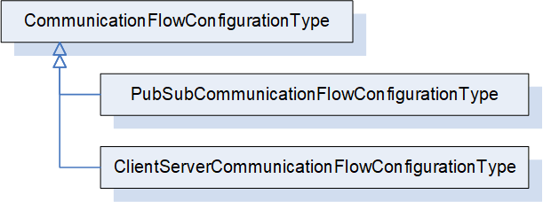
6.13.2 CommunicationFlowConfigurationType definition
The CommunicationFlowConfigurationType is an abstract type. It is formally defined in Table 97.
| Attribute | Value | ||||
| BrowseName | 4:CommunicationFlowConfigurationType | ||||
| IsAbstract | True | ||||
| References |
Node
Class | BrowseName | DataType | TypeDefinition | Other |
|---|---|---|---|---|---|
| Subtype of the 0:BaseObjectType defined in OPC 10000-5 | |||||
| 0:HasSubtype | ObjectType | 4:PubSubCommunicationFlowConfigurationType | Defined in 6.13.3 | ||
| ConformanceUnits | |||||
|---|---|---|---|---|---|
| UAFX ConnectionManager Base |
PubSubCommunicationFlowConfigurationType indicates the usage of PubSub as the communication model for the Connections. It is formally defined in 6.13.3.
ClientServerCommunicationFlowConfigurationType may be defined in a future release to indicate the usage of Client Server as the communication model for the Connections.
6.13.3 PubSubCommunicationFlowConfigurationType
6.13.3.1 Overview
The PubSubCommunicationFlowConfigurationType defines the PubSub-specific communication configuration (see OPC 10000-14).
For examples of PubSubCommunicationFlowConfigurationType, see Annex E.
The PubSubCommunicationFlowConfigurationType is illustrated in Figure 44.
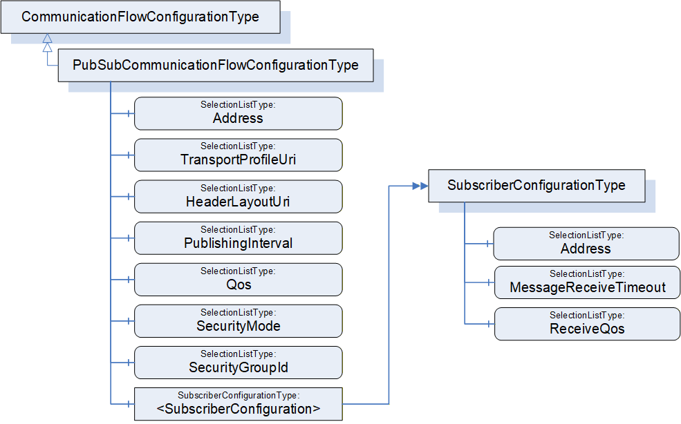
6.13.3.2 PubSubCommunicationFlowConfigurationType definition
The PubSubCommunicationFlowConfigurationType is formally defined in Table 98.
The PubSubCommunicationFlowConfigurationType contains the configuration needed for both the publishing and subscribing of an information flow. In terms of this model, the information flow can be linked with ConnectionEndpointConfiguration Objects to explicitly indicate the Publisher and Subscriber(s) of the information flow. The linkage is provided by ToOutboundFlow and ToInboundFlow References (defined in 11.24 and 11.25; see 6.8.2 for additional description). There are, in general, two types of information flows: 1 to 1 (unicast) or 1 to N (multicast), which imply the following relations:
Unicast
Publishing ConnectionEndpointConfiguration, if specified, references the PubSubCommunicationFlowConfiguration Object using the ToOutboundFlow Reference.
Subscribing ConnectionEndpointConfiguration, if specified, shall reference the single instance of the <SubscriberConfiguration> using the ToInboundFlow Reference.
Multicast
Publishing ConnectionEndpointConfiguration, if specified, references the PubSubCommunicationFlowConfiguration Object using the ToOutboundFlow Reference.
Subscribing ConnectionEndpointConfigurations, if specified, shall reference the <SubscriberConfiguration> Objects using the ToInboundFlow Reference. There can be as many <SubscriberConfiguration> Objects as there are Subscribers, in which case each ConnectionEndpointConfiguration references its corresponding configuration. <SubscriberConfiguration> Objects may be shared by the ConnectionEndpointConfiguration Objects.
The referenced SubscriberConfiguration does not replicate information that is contained in its parent object, but the parent information is required to establish the Connection.
For the usage of SelectionLists, see 6.8.1.
| Attribute | Value | ||||
| BrowseName | 4:PubSubCommunicationFlowConfigurationType | ||||
| IsAbstract | False | ||||
| References |
Node
Class | BrowseName | DataType | TypeDefinition | Other |
|---|---|---|---|---|---|
| Subtype of the 4:CommunicationFlowConfigurationType | |||||
| 0:HasComponent | Variable | 4:Address | 0:NetworkAddressDataType | 0:SelectionListType | O |
| 0:HasComponent | Variable | 4:TransportProfileUri | 0:String | 0:SelectionListType | O |
| 0:HasComponent | Variable | 4:HeaderLayoutUri | 0:String | 0:SelectionListType | O |
| 0:HasComponent | Variable | 4:PublishingInterval | 0:Duration | 0:SelectionListType | O |
| 0:HasComponent | Variable | 4:Qos | 4:CommunicationFlowQosDataType | 0:SelectionListType | O |
| 0:HasComponent | Variable | 4:SecurityMode | 0:MessageSecurityMode | 0:SelectionListType | O |
| 0:HasComponent | Variable | 4:SecurityGroupId | 0:String | 0:SelectionListType | O |
| 0:HasComponent | Object | 4:<SubscriberConfiguration> | 4:SubscriberConfigurationType | OP | |
| ConformanceUnits | |||||
|---|---|---|---|---|---|
| UAFX ConnectionManager PubSubCommunicationFlowConfiguration |
The optional Address specifies the destination network address to be used for transmission of NetworkMessages by the Publisher of the information flow. This is an abstract type, and a concrete subtype shall be used. For the usage of Address, see OPC 10000-14 Clause “PubSub mappings”, Subclause “Transport protocol mappings”. The configuration is invalid if Address is omitted here and in <SubscriberConfiguration>.
The optional TransportProfileUri specifies the transport protocol mapping and the message mapping to be used. If TransportProfileUri is omitted, the default transport protocol for the Address shall be used. For the definition of TransportProfileUri, see OPC 10000-14.
The optional HeaderLayoutUri specifies the UADP header formats for both NetworkMessages and DataSetMessages. If HeaderLayoutUri is omitted, a fixed layout for periodic data shall be used (http://opcfoundation.org/UA/PubSub-Layouts/UADP-Periodic-Fixed). For the definition of HeaderLayoutUri, see OPC 10000-14.
The optional PublishingInterval specifies the interval to be used for publishing NetworkMessages. For the definition of PublishingInterval, see OPC 10000-14.
The optional Qos specifies the Quality of Service to be used for the information flow. For the definition of CommunicationFlowQosDataType, see 10.12. Qos ReceiveQos may be overridden by a <SubscriberConfiguration> (see 6.13.3.3).
SecurityMode specifies the security mode to be used for the information flow. For the definition of SecurityMode, see OPC 10000-14.
SecurityGroupId specifies the security group to be used for the information flow. For the definition of SecurityGroupId, see OPC 10000-14.
The optional <SubscriberConfiguration> represents instances of SubscriberConfigurationType. It defines the configuration of the information flow for the Subscriber(s). <SubscriberConfiguration> is omitted for an autonomous publisher.
6.13.3.3 SubscriberConfigurationType definition
The SubscriberConfigurationType is formally defined in Table 99. It describes the Subscriber-specific information for the Subscriber of an information flow. The configuration of the Subscriber requires additional information from the parent object, which applies to all Subscribers.
| Attribute | Value | ||||
| BrowseName | 4:SubscriberConfigurationType | ||||
| IsAbstract | False | ||||
| References |
Node
Class | BrowseName | DataType | TypeDefinition | Other |
|---|---|---|---|---|---|
| Subtype of the 0:BaseObjectType defined in OPC 10000-5 | |||||
| 0:HasComponent | Variable | 4:Address | 0:NetworkAddressDataType | 0:SelectionListType | O |
| 0:HasComponent | Variable | 4:MessageReceiveTimeout | 0:Duration | 0:SelectionListType | M |
| 0:HasComponent | Variable | 4:ReceiveQos | 0:ReceiveQosDataType[] | 0:SelectionListType | O |
| ConformanceUnits | |||||
|---|---|---|---|---|---|
| UAFX ConnectionManager PubSubCommunicationFlowConfiguration |
The optional Address specifies the network address to be used for the reception of NetworkMessages at the Subscriber of the information flow. This is an abstract type, and a concrete subtype shall be used. For the usage of Address, see OPC 10000-14 Clause “PubSub mappings”, Subclause “Transport protocol mappings”. If Address is omitted and the parent Object contains a multicast network address, the Address of the parent Object shall be used for the Subscriber. If Address is omitted and the parent Object contains a unicast network address, the default reception address with the default port shall be used (e.g., “opc.udp://localhost”; for details, see OPC 10000-14). The configuration is invalid if Address is omitted here and in the parent Object.
The MessageReceiveTimeout specifies the maximum acceptable time between DataSetMessages. Received by the Subscriber. For the definition of MessageReceiveTimeout, see OPC 10000-14.
The optional ReceiveQos specifies the Quality of Service to be used for the Subscriber of the information flow. It shall only be present if Qos is present in the parent Object. If present, ReceiveQos will override Qos ReceiveQos of the parent Object. For the definition of ReceiveQos, see OPC 10000-14.
6.13.4 ClientServerCommunicationFlowConfigurationType
The ClientServerCommunicationFlowConfigurationType may be defined in a future version of this document.
6.14 AutomationComponentConfigurationType
6.14.1 Overview
The AutomationComponentConfigurationType ObjectType holds the information to be used for locating an AutomationComponent within a Server.
The AutomationComponentConfigurationType is illustrated in Figure 45.
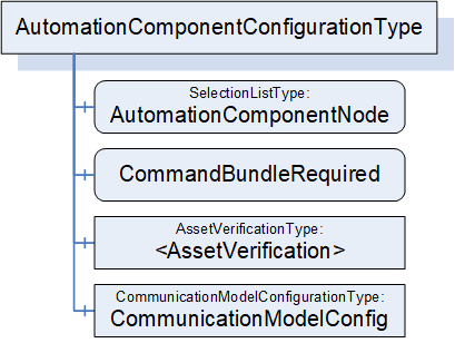
6.14.2 AutomationComponentConfigurationType definition
The AutomationComponentConfigurationType is formally defined in Table 100.
| Attribute | Value | ||||
| BrowseName | 4:AutomationComponentConfigurationType | ||||
| IsAbstract | False | ||||
| References |
Node
Class | BrowseName | DataType | TypeDefinition | Other |
|---|---|---|---|---|---|
| Subtype of the 0:BaseObjectType defined in OPC 10000-5 | |||||
| 0:HasComponent | Variable | 4:AutomationComponentNode | 4:PortableNodeIdentifier | 0:SelectionListType | M |
| 4:HasCharacteristic | Variable | 4:CommandBundleRequired | 0:Boolean | 0:BaseDataVariableType | M |
| 4:HasAssetToVerify | Object | 4:<AssetVerification> | 4:AssetVerificationType | OP | |
| 0:HasComponent | Object | 4:CommunicationModelConfig | 4:CommunicationModelConfigurationType | O | |
| ConformanceUnits | |||||
|---|---|---|---|---|---|
| UAFX ConnectionManager Base |
AutomationComponentNode specifies the AutomationComponent that is to be used for establishing Connections. If a PortableRelativePath is specified, the path shall be relative to FxRoot.
CommandBundleRequired, when TRUE, specifies that the ConnectionManager shall bundle commands to this AutomationComponent.
AssetVerification holds the Asset verification parameters for an Asset associated with this AutomationComponent. The AssetVerificationType is defined in 6.15.2.
CommunicationModelConfig provides the ConfigurationData specific to the communication model utilised by the Connections.
6.15 AssetVerificationType
6.15.1 Overview
The AssetVerificationType ObjectType holds the information to be used for compatibility verification of an Asset.
The AssetVerificationType is illustrated in Figure 46.
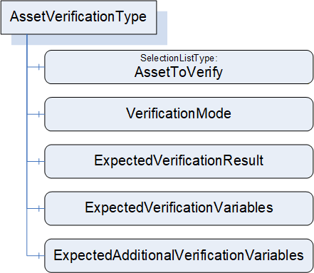
6.15.2 AssetVerificationType definition
The AssetVerificationType is formally defined in Table 101.
| Attribute | Value | ||||
| BrowseName | 4:AssetVerificationType | ||||
| IsAbstract | False | ||||
| References |
Node
Class | BrowseName | DataType | TypeDefinition | Other |
|---|---|---|---|---|---|
| Subtype of the 0:BaseObjectType defined in OPC 10000-5 | |||||
| 0:HasComponent | Variable | 4:AssetToVerify | 4:PortableNodeIdentifier | 0:SelectionListType | M |
| 0:HasComponent | Variable | 4:VerificationMode | 2:AssetVerificationModeEnum | 0:BaseDataVariableType | M |
| 0:HasComponent | Variable | 4:ExpectedVerificationResult | 2:AssetVerificationResultEnum | 0:BaseDataVariableType | M |
| 0:HasComponent | Variable | 4:ExpectedVerificationVariables | 4:PortableNodeIdentifierValuePair[] | 0:BaseDataVariableType | M |
| 0:HasComponent | Variable | 4:ExpectedAdditionalVerificationVariables | 4:PortableNodeIdentifierValuePair[] | 0:BaseDataVariableType | M |
| ConformanceUnits | |||||
|---|---|---|---|---|---|
| UAFX ConnectionManager Base |
AssetToVerify specifies the expected Asset to be verified. If a PortableRelativePath is specified, the path shall be relative to AutomationComponentNode.
VerificationMode is the mode to use for the verification (compatibility and/or identity).
ExpectedVerificationResult is the expected level of compatibility that this Asset shall provide.
ExpectedVerificationVariables hold the variables to be verified for compatibility and/or identity. It is expected that this list contains IdentifierBrowsePath with a PortableRelativePath as Keys using BrowseNames as defined in Table 31.
ExpectedAdditionalVerificationVariables hold the variables to be verified for compatibility and/or identity. If a PortableRelativePath is specified, the path shall be relative to the expected Asset.
6.16 CommunicationModelConfigurationType
6.16.1 Overview
The CommunicationModelConfigurationType ObjectType provides the configuration data specific to the communication model utilised by the Connections.
The CommunicationModelConfigurationType is illustrated in Figure 47.
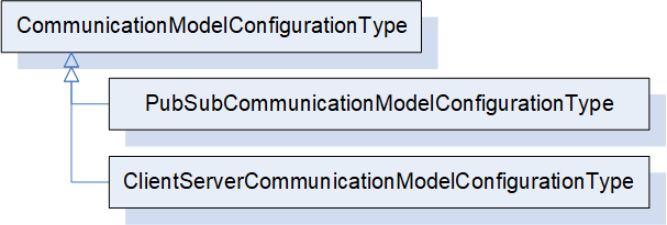
PubSubCommunicationModelConfigurationType provides the configuration data specific to the usage of PubSub as the communication model for the Connections. It is formally defined in 6.16.3.
ClientServerCommunicationModelConfigurationType indicates the usage of Client Server as the communication model for the Connections. It may be defined in a future release.
6.16.2 CommunicationModelConfigurationType definition
This ObjectType is the abstract base type of all communication model-specific configuration data.
The CommunicationModelConfigurationType is formally defined in Table 102.
| Attribute | Value | ||||
| BrowseName | 4:CommunicationModelConfigurationType | ||||
| IsAbstract | True | ||||
| References |
Node
Class | BrowseName | DataType | TypeDefinition | Other |
|---|---|---|---|---|---|
| Subtype of the 0:BaseObjectType defined in OPC 10000-5 | |||||
| 0:HasSubtype | ObjectType | 4:PubSubCommunicationModelConfigurationType | Defined in 6.16.36.17.3 | ||
| ConformanceUnits | |||||
|---|---|---|---|---|---|
| UAFX ConnectionManager Base |
6.16.3 PubSubCommunicationModelConfigurationType
6.16.3.1 Overview
The PubSubCommunicationModelConfigurationType defines the communication model-related configuration information for the usage of PubSub as the communication model (see OPC 10000-14).
The PubSubCommunicationModelConfigurationType is illustrated in Figure 48.
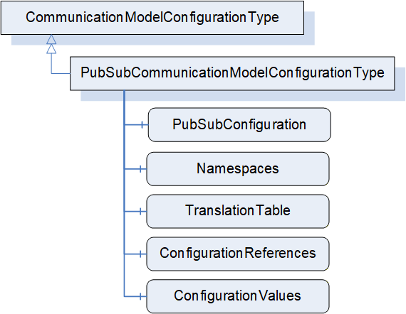
6.16.3.2 PubSubCommunicationModelConfigurationType definition
The PubSubCommunicationModelConfigurationType is formally defined in Table 103.
| Attribute | Value | ||||
| BrowseName | 4:PubSubCommunicationModelConfigurationType | ||||
| IsAbstract | False | ||||
| References |
Node
Class | BrowseName | DataType | TypeDefinition | Other |
|---|---|---|---|---|---|
| Subtype of the 4:CommunicationModelConfigurationType | |||||
| 0:HasComponent | Variable | 4:PubSubConfiguration | 0:PubSubConfiguration2DataType | 0:BaseDataVariableType | M |
| 0:HasComponent | Variable | 4:Namespaces | 0:String[] | 0:BaseDataVariableType | M |
| 0:HasComponent | Variable | 4:TranslationTable | 4:NodeIdTranslationDataType[] | 0:BaseDataVariableType | M |
| 0:HasComponent | Variable | 4:ConfigurationReferences | 0:PubSubConfigurationRefDataType[] | 0:BaseDataVariableType | M |
| 0:HasComponent | Variable | 4:ConfigurationValues | 0:PubSubConfigurationValueDataType[] | 0:BaseDataVariableType | M |
| ConformanceUnits | |||||
|---|---|---|---|---|---|
| UAFX ConnectionManager PubSubCommunicationModelConfiguration |
The PubSubConfiguration modifies the existing PubSub configuration on the addressed Server when establishing Connections. The PubSubConfiguration2DataType is defined in OPC 10000-14.
Namespaces contains namespace URIs for NamespaceIndex used in the PubSubConfiguration. Examples are NodeIds contained in PublishedDataSets. The NamespaceIndex in the PubSubConfiguration will need to be updated to reflect the NamespaceIndexes in the addressed Server.
NodeIds contained in the PubSubConfiguration, which use the special namespace “http://opcfoundation.org/UA/FX/CM/Translation/”, are not valid NodeIds but placeholders which shall be resolved before the ConnectionManager can use the PubSubConfiguration for connection establishment. The resolution consists of 2 steps. The first step is done locally within the ConnectionManager, and it involves the conversion of these NodeIds to PortableNodeIdentifiers according to the TranslationTable. The second step involves the resolution of the PortableNodeIdentifiers to actual NodeIds of the Nodes on the target Server (see 13). If a PortableNodeIdentifier is represented by a PortableRelativePath, the starting node of such a path depends on which PubSubConfiguration element the identifier corresponds to. If the identifier corresponds to a published or subscribed Variable (e.g., PublishedVariable of PublishedVariableDataType or TargetNodeId of FieldTargetDataType), the path shall start at the hosting AutomationComponent.
ConfigurationReferences points to elements within the PubSubConfiguration and indicates whether they are to be added, matched, modified, or removed. The PubSubConfigurationRefDataType is defined in OPC 10000-14.
PubSubConfiguration and ConfigurationReferences are generated by the engineering tool creating the ConnectionConfigurationSet or by the ConnectionManager. The relation of configuration elements in PubSubConfiguration to a ConnectionEndpoint is provided by the CommunicationLinks (see 6.12.2).
For examples of how to establish the configuration information for AutomationComponents, see E.2, and for the SKS, see E.5.
The ConfigurationValues Variable contains the names and identifiers that were assigned by EstablishConnections. They correspond to null names or 0 identifiers in the PubSubConfiguration.
OPC UA FX allows multiple ConnectionManagers to establish Connections to a single AutomationComponent independently of each other. It also allows any Client to establish Connections. An AutomationComponent may even receive PubSub configuration (unrelated to OPC UA FX) via the corresponding Methods exposed in the PubSub configuration model. Coordinating all possible sources of PubSub configuration can become a very difficult task. Since OPC 10000-14 requires certain elements of the PubSub configuration model to be unique (e.g., WriterGroupId and DataSetWriterId), such scenarios may lead to conflicting PubSub configurations (e.g., identical WriterGroupIds configured by two different ConnectionManagers).
Since the Clients passing in such (potentially conflicting) PubSub configurations are unaware of each other, resolving conflicting configuration elements can only be provided by the entity receiving them. In scenarios where PubSub configuration is generated by a single entity (e.g., an engineering tool), this does not apply since the entity generating PubSub configuration could uniquely determine all names and identifiers.
For certain elements in PubSubConfiguration, the entity generating the ConnectionConfigurationSet may set their names (i.e., PubSubConnection, ReaderGroup, WriterGroup, DataSetReader, DataSetWriter) to a specific value or to null. If set to null, a unique name is generated by the addressed AutomationComponent when passing the PubSubConfiguration using the EstablishConnections SetCommunicationConfigurationCmd. If it has a specific value, that value will be used.
For certain elements in PubSubConfiguration, the entity generating the ConnectionConfigurationSet may set their identifiers (i.e., PublisherId, WriterGroupId, WriterId) to a specific value or to null. If set to null, a unique identifier is generated by the addressed AutomationComponent (see OPC 10000-14). Two options exist:
The ConnectionManager could apply identifiers (WriterGroupIds, WriterIds) that it reserved on the AutomationComponent with a previously issued EstablishConnections ReserveCommunicationIdsCmd before passing PubSubConfigurations using EstablishConnections SetCommunicationConfigurationCmd. PubSubConnections need specific handling; for details, see additional information in later paragraphs.
The ConnectionManager could pass the PubSubConfiguration using the EstablishConnections SetCommunicationConfigurationCmd with identifiers set to null, allowing the AutomationComponent to generate and assign the identifiers.
It is recommended that the entity generating the ConnectionConfigurationSet uses null Names and identifiers. Additional details for each identifier are provided below. See Annex E.5 for examples.
For PubSubConnections, specific handling applies: OPC 10000-14 requires a PubSubConnection to have a unique Address across all PubSubConnections. This implies that there is exactly one PubSubConnection with a specific Address, determining the PublisherId to be used for that Address. It is therefore recommended that the entity generating the ConnectionConfigurationSet sets the names and PublisherIds of PubSubConnections to null and that the ConnectionManager uses ElementAdd and ElementMatch with a null name and a null PublisherId for PubSubConnections. This allows the sharing of existing PubSubConnections. If the PubSubConnection matches, the PublisherId of the matching PubSubConnection shall be used; otherwise, a new PubSubConnection is created with the default PublisherId. The ConnectionManager shall adapt the PubSubConfiguration of subscribing AutomationComponents with the returned PublisherIds as required.
It is recommended to use ElementAdd for WriterGroups and ReaderGroups under the assumption that each ConnectionManager maintains groups separate from other ConnectionManagers.
After a ConnectionConfigurationSet is edited (see 6.7.4), the ConnectionManager shall update the PubSubConfiguration (see Annex E.5 for examples).
6.16.4 ClientServerCommunicationModelConfigurationType
The ClientServerCommunicationModelConfigurationType may be defined in a future version of this document.