The ConnectionManager processes ConnectionConfigurationSets to establish connections. This clause contains examples for ConnectionConfigurationSets. A ConnectionConfigurationSet contains a set of logical connections, which the ConnectionManager establishes as a complete set.
A ConnectionConfigurationSet can contain
- a single logical connection between two FunctionalEntities,
- multiple logical connections between FunctionalEntities located on two AutomationComponents,
- or multiple logical connections between FunctionalEntities located on multiple AutomationComponents.
The following examples illustrate the usage of ConnectionConfigurationSets. However, the usage of ConnectionConfigurationSets is not restricted to the examples.
Figure E.1 depicts the configuration elements contained in a ConnectionConfigurationSet and their relation to each other for a single logical connection. The relation between the configuration elements (present on the ConnectionManager) and their resulting runtime elements (present or created on the AutomationComponents being part of the logical connection) is indicated by dashed arrows.
+-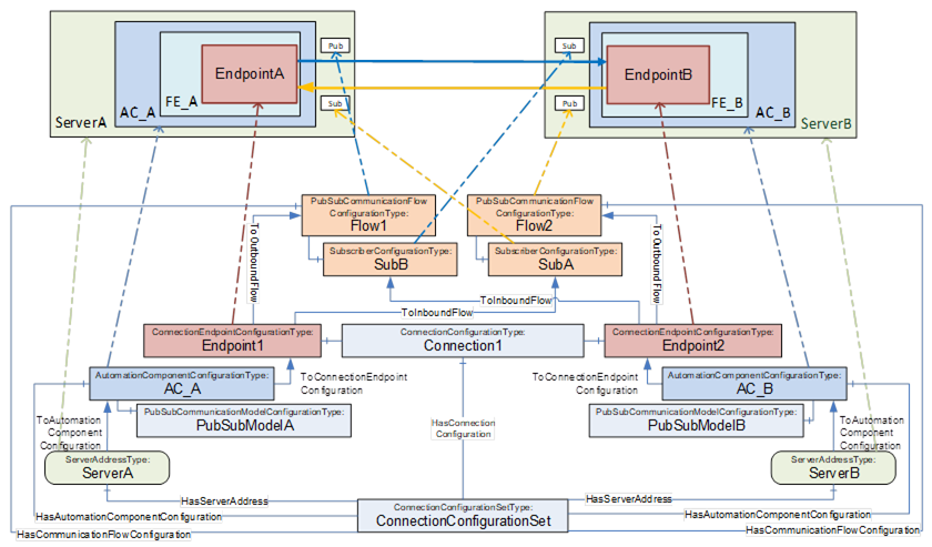
Figure E.1 – ConnectionConfigurationSet overview (single logical connection)
This ConnectionConfigurationSet contains one Connection configuration, Connection1, which contains the configuration for a single logical connection.
Connection1 contains two ConnectionEndpointConfigurations for the two ConnectionEndpoints EndpointA and EndpointB. Each ConnectionEndpointConfiguration contains all parameters required for creating the ConnectionEndpoint, verifying the affected FunctionalEntity, requesting ControlGroups, and application configuration.
The ConnectionConfigurationSet provides two PubSubCommunicationFlowConfiguration Objects, Flow1 and Flow2. They provide communication configuration (e.g., interval, timeout or QoS) and are referenced by the Endpoints with ToOutboundFlow and ToInboundFlow References. While an Object of type SubscriberConfigurationType (SubA, SubB) contains configuration for the Subscriber only, its parent PubSubCommunicationFlowConfigurationType Object contains configuration relevant for both the Publisher and Subscriber. The configuration contained in Flow1 is used for setting up the Publisher on ServerA, and the configuration contained in SubB and Flow1 is for setting up the Subscriber on ServerB. Flow2 and SubA are used for setting up the Publisher and Subscriber in the opposite direction.
EndpointA and EndpointB are each referenced by an AutomationComponentConfiguration, AC_A and AC_B, which hold the FunctionalEntities involved in this logical connection. AC_A and AC_B contain the parameters for verifying Assets. AC_A and AC_B could optionally include the PubSubCommunicationModelConfiguration, PubSubModelA and PubSubModelB.
AC_A and AC_B are each referenced by a ServerAddress, ServerA and ServerB, containing the configuration required for the ConnectionManager to be able to establish a secure Session to ServerA and ServerB.
Multiple logical connections can be configured between two or more AutomationComponents using unicast or multicast communication. Examples for each of the options are illustrated.
Figure E.2 depicts the configuration elements contained in a ConnectionConfigurationSet and their relation to each other for multiple logical connections between two AutomationComponents.
Often, traffic between two AutomationComponents will be optimised to use one NetworkMessage. EndpointA1 and EndpointA2 share PubSubCommunicationFlowConfiguration Flow1 with a ToOutboundFlow Reference and share SubscriberConfiguration SubA with a ToInboundFlow Reference to ensure the same set of parameters for the outbound and inbound NetworkMessage. The same applies to EndpointB1 and EndpointB2.
A variant of this scenario is illustrated in Figure E.3. In this example, one of the connections requires a fast PublishingInterval and Qos for the exchange of real-time data, and the other connection requires a slow PublishingInterval and best-effort for the exchange of status data.
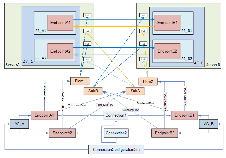
Figure E.2 – Multiple logical connections between two AutomationComponents
NOTE In this and the following figures, ServerAddress, HasCommunicationFlowConfiguration References, and PubSubCommunicationModelConfigurations are omitted for brevity. Refer to Figure E.1 for a complete view.
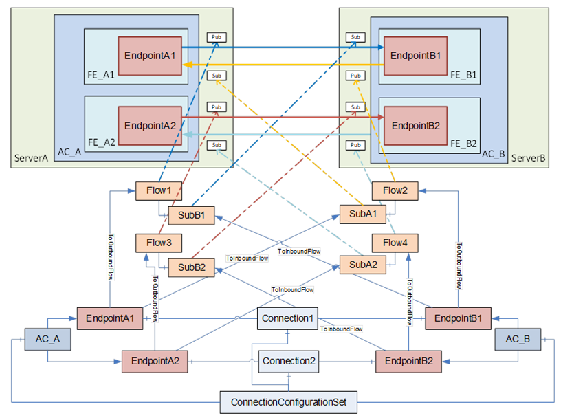
Figure E.3 – Multiple logical connections between two AutomationComponents (variant)
Figure E.4 depicts the configuration elements contained in a ConnectionConfigurationSet and their relation to each other for multiple logical connections among multiple AutomationComponents.
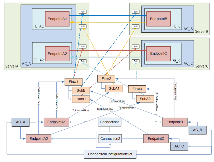
Figure E.4 – Multiple logical connections using multicast
This ConnectionConfigurationSet contains two ConnectionConfigurations, Connection1 and Connection2.
Since outbound traffic from AC_A is using multicast in this scenario, both EndpointA1 and EndpointA2 refer to PubSubCommunicationFlowConfiguration Flow1 with a ToOutboundFlow Reference. Flow1 contains two SubscriberConfigurations, SubB and SubC. This allows, for example, EndpointB and EndpointC to have different settings for the MessageReceiveTimeout. EndpointB and EndpointC refer to their specific Subscriber configuration with ToInboundFlow. If EndpointB and EndpointC do not require different SubscriberConfigurations, both endpoints could also refer to a single instance of SubscriberConfigurationType.
The unicast traffic in the opposite direction can also be modelled in various ways. The example shown in Figure E.4 allows different configuration settings for the unicast traffic with the PubSubCommunicationFlowConfiguration Flow2 and Flow3.
A variant is shown in Figure E.5, which shares the same set of parameters for the unicast Publishers and Subscribers.
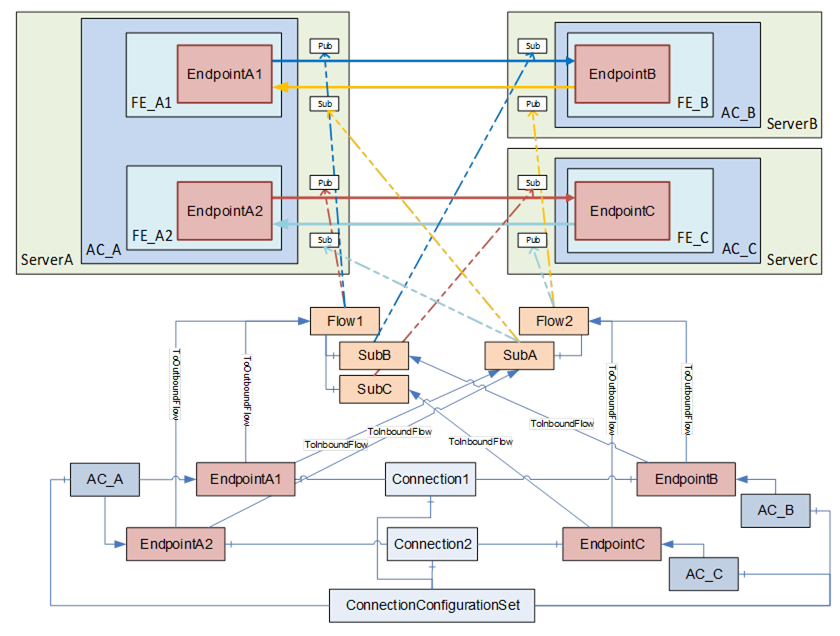
Figure E.5 – Multiple logical connections using multicast (variant)
The ConnectionManager uses the information in the ConnectionConfigurationSet to establish all contained Connections. The configuration information required as input to call EstablishConnections on a particular AutomationComponent can be retrieved by following the References starting at each of the AutomationComponents listed in the ConnectionConfigurationSet.
The ConnectionManager iterates through the AutomationComponentConfigurations. The ConnectionManager establishes a secure Session based on the information contained in the ServerAddress (see 13.3.2) for each AutomationComponent. The ConnectionManager must resolve all PortableNodeIdentifiers contained in the configuration information (see 13.3.3).
NOTE The interaction of the ConnectionManager with AutomationComponents to establish Client Server-based Connections will be provided in a future version of this document.
If a PubSubCommunicationModelConfiguration was generated by the engineering tool generating the ConnectionConfigurationSet, the ConnectionManager must resolve the NodeIds contained in it (see 6.16.3.2). The ConnectionManager must ensure that the PubSubCommunicationFlowConfigurations and SubscriberConfigurations are reflected in the PubSubCommunicationModelConfiguration.
If the PubSubCommunicationModelConfiguration was not supplied by the engineering tool, the ConnectionManager must create one based on the information contained in the PubSubCommunicationFlowConfigurations.
The PubSubConfiguration contained in the PubSubCommunicationModelConfiguration could contain information:
- which is targeted for the AutomationComponent (PublishedDataSets, Connections, SubscribedDataSets, ConfigurationProperties and defaultSecurityKeyServices), illustrated in Figure E.6 as red boxes with straight lines;
- which is targeted for the SKS (SecurityGroups and PubSubKeyPushTargets), illustrated in Figure E.6 as green boxes with dashed lines;
- and information which is ignored, illustrated in Figure E.6 as grey boxes with dashed double dotted lines (see CloseAndUpdate in OPC 10000-14).
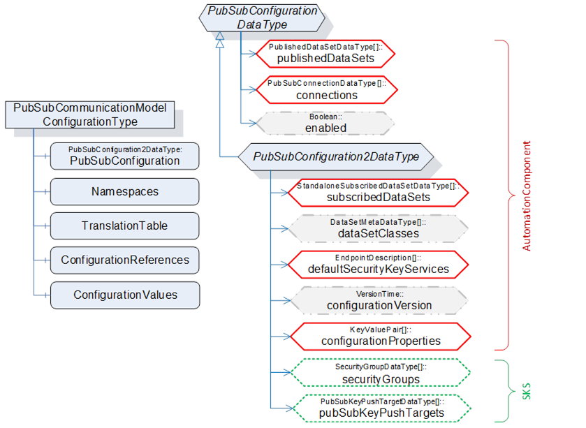
Figure E.6 – PubSubConfiguration illustration
The ConnectionManager establishes all Connections by calling EstablishConnections on each AutomationComponent (see 6.7.5.3). This includes the communication model information targeted for the AutomationComponent (i.e., SecurityGroups and PubSubKeyPushTargets are omitted). If using PubSub, a specific sequence of calls could be required (see E.2.2).
If Connections require security (authorisation or encryption), the ConnectionManager also configures the SKS (see E.5). It is recommended to hold the SKS configuration information (i.e., SecurityGroups and PubSubKeyPushTargets) in the ConnectionConfigurationSet (see 6.8.2). Alternatively, the PubSubCommunicationModelConfiguration of the AutomationComponent could be used.
A ConnectionManager typically stores (in a vendor-specific manner) all resolved NodeIds.
For PubSub as a communication model, OPC 10000-14 requires certain configuration values (e.g., PublisherId, WriterGroupId, and DataSetWriterId) to match the Publisher and its corresponding Subscribers. However, unique IDs could be generated by the addressed AutomationComponent and are not known by the ConnectionManager beforehand.
OPC 10000-14 provides two ways of generating unique IDs by the AutomationComponent, either by providing a null ID when configuring PubSub or by reserving IDs.
Assuming a simple example, where a ConnectionManager processes a ConnectionConfigurationSet containing logical connections between two AutomationComponents, the sequence illustrated in Figure E.7 could be used.
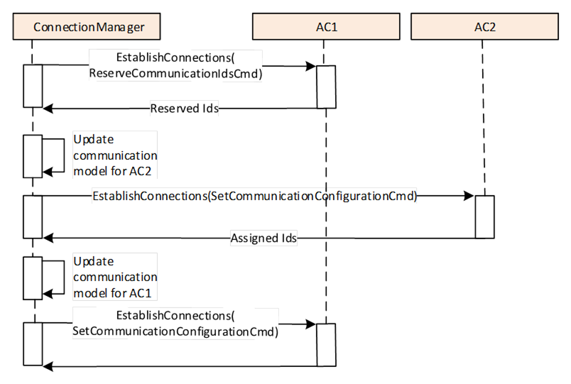
Figure E.7 – Sequence for establishing connections (two AutomationComponents)
The ConnectionManager executes the following steps for establishing the Connections:
- The ConnectionManager calls EstablishConnections on AC1 using the ReserveCommunicationIdsCmd to reserve WriterGroupIds and DataSetWriterIds for the publishing side (i.e., WriterGroups and DataSetWriters for AC1) and to retrieve the default PublisherId. This Call will typically contain the VerifyAssetCmd and the VerifyFunctionalEntityCmd if required; all further commands for AC1 are issued in step (3).
- The ConnectionManager updates the communication configuration for AC2 regarding the subscribing side (DataSetReaders) using the IDs reserved in step (1). The ConnectionManager will set the publishing side of the communication configuration for AC2 to null IDs. The ConnectionManager calls EstablishConnections on AC2 using the SetCommunicationConfigurationCmd to add the updated communication configuration. AC2 assigns IDs to the publishing side of the communication configuration and returns the information. This Call will typically contain all other required commands.
- The ConnectionManager updates the communication configuration for AC1 regarding the publishing side using the IDs reserved in step (1) and the subscribing side using the IDs returned from step (2). The ConnectionManager calls EstablishConnections on AC1 using the SetCommunicationConfigurationCmd to add the complete communication configuration. This Call will typically contain all further required commands.
Multiple logical connections across multiple AutomationComponents could require more steps. Assume that a ConnectionManager must establish a ConnectionConfigurationSet containing logical connections between multiple AutomationComponents.
Figure E.8 illustrates an example of such a ConnectionConfigurationSet. For this scenario, the ConnectionManager could set up the logical connections as follows:
- The ConnectionManager calls EstablishConnections on AC1, AC2, and AC3 using the ReserveCommunicationIdsCmd to reserve WriterGroupIds and DataSetWriterIds for the publishing side (i.e., WriterGroups and DataSetWriters for AC1, AC2 and AC3) and to retrieve the default PublisherId.
- The ConnectionManager updates the communication configuration for AC1, AC2, and AC3 regarding the publishing and subscribing side (DataSetReaders) using the IDs reserved in step (1). The ConnectionManager then calls EstablishConnections on AC1, AC2, and AC3 using the SetCommunicationConfigurationCmd to add the complete communication configuration.
The ConnectionManager could use the sequence illustrated in Figure E.8.
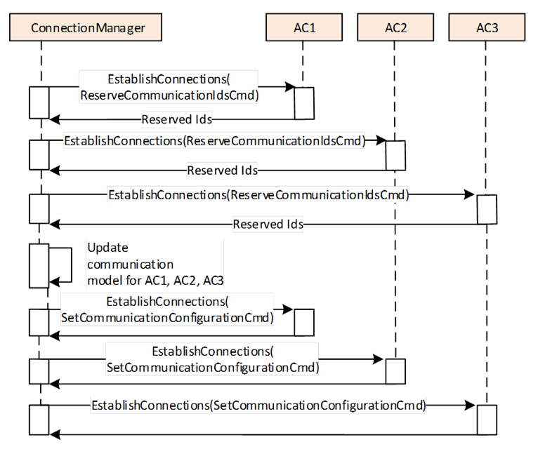
Figure E.8 – Sequence for establishing connections (multiple AutomationComponents)
To set up this scenario, six Calls are needed in total (2 Calls per AutomationComponent). The Calls to different AutomationComponents can be issued in parallel.
If all logical connections are related to one AutomationComponent in our sample, this would be AC1. The sequence could be optimised as follows:
- The ConnectionManager calls EstablishConnections on AC1 using the ReserveCommunicationIdsCmd to reserve WriterGroupIds and DataSetWriterIds for the publishing side (i.e., WriterGroups and DataSetWriters for AC1) and to retrieve the default PublisherId.
- The ConnectionManager updates the communication configuration for AC2 and AC3 regarding the subscribing side (DataSetReaders) using the IDs reserved in step (1). The ConnectionManager will set the publishing side of the communication configuration for AC2 and AC3 to null IDs. The ConnectionManager calls EstablishConnections on AC1 and AC2 using the SetCommunicationConfigurationCmd to add the updated communication configuration. While adding the communication configuration, AC2 and AC3 assign IDs to the publishing side of the communication configuration and returns that information.
- The ConnectionManager updates the communication configuration for AC1 regarding the publishing side using the IDs reserved in step (1) and the IDs returned from step (2). The ConnectionManager calls EstablishConnections on AC1 using the SetCommunicationConfigurationCmd to add the complete communication configuration.
This optimised sequence is illustrated in Figure E.9
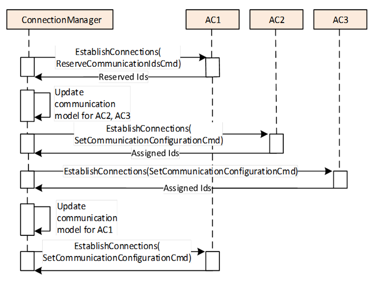
Figure E.9 – Optimised Sequence for establishing connections (multiple AutomationComponents)
The ConnectionManager could also use a variant of the sequences above, for example, using SetCommunicationConfigurationCmd, with the publishing side of the communication configuration having null IDs instead of using the ReserveCommunicationIdsCmd. In this case, the subscribing side of the communication configuration will be added in a separate step.
The concepts for enable, disable, and remove are described in normative text (see 6.2.4 and 6.2.5), and since caching of NodeIds is vendor-specific, no example is provided.
This clause describes the configuration settings for the connection types defined in Clause 5.5.1 using PubSub as a communication model. For simplicity, all samples describe a single logical connection contained in the ConnectionConfigurationSet. Note, however, that as shown in E.1.3, a ConnectionConfigurationSet can contain multiple Connections, which could have different connection types.
The examples provide illustrations of how PubSub communication can be configured. The configuration contains various settings that have an influence on the communication model, including Address, PublishingInterval, QoS, MessageReceiveTimeout, ReceiveQos and SecurityMode (see 6.13.3 for additional details). Some of these settings can be complex to apply, such as the Address. Depending on the type of connection, this Address might contain a destination address, a receiving address, or a multicast address.
To set up the PubSubConfiguration for the bidirectional connection (illustrated in Figure E.1), information from multiple configuration elements is used, as illustrated in Figure E.10. For a simpler overview, configuration data not related to the communication model and Endpoint2 are omitted.
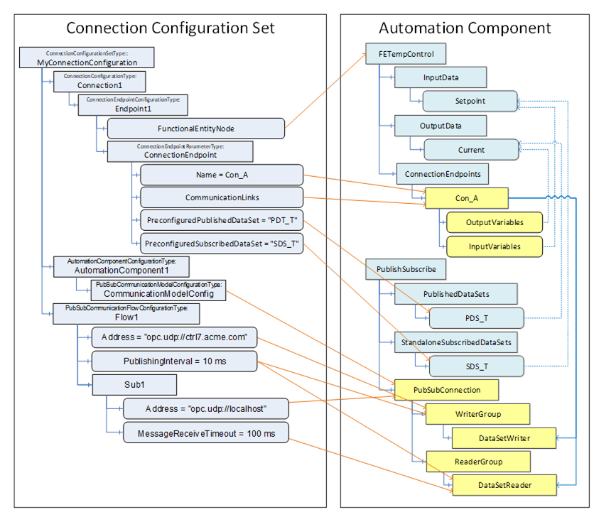
Figure E.10 – Configuring PubSub
CommunicationModelConfig contains the PubSub configuration elements to be applied to the AutomationComponent. The ConnectionManager uses the configuration information in Flow1 and Sub1 to update the communication model. CommunicationLinks indicate which DataSetReader and DataSetWriter contained in the communication model are relevant for this ConnectionEndpoint. This information is also used to set up the ToDataSetReader and ToDataSetWriter References on Con_A.
The Connection configuration for a bidirectional connection contains the following configuration information (see Figure E.11):
- EndpointA, indicating InputVariables and OutputVariables,
- EndpointB, indicating InputVariables and OutputVariables,
- Flow1 and SubB describing the configuration for the information flow from EndpointA to EndpointB,
- Flow2 and SubA for the information flow from EndpointB to EndpointA.
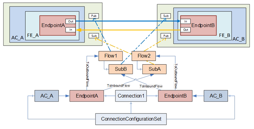
Figure E.11 – Bidirectional connection illustration
The Connection configuration for a unidirectional connection with heartbeat contains the following configuration information (see Figure E.12):
- EndpointA, indicating OutputVariables,
- EndpointB, indicating InputVariables,
- Flow1 and SubB describing the configuration for the information flow from EndpointA to EndpointB,
- Flow2 and SubA for the heartbeat from EndpointB to EndpointA.
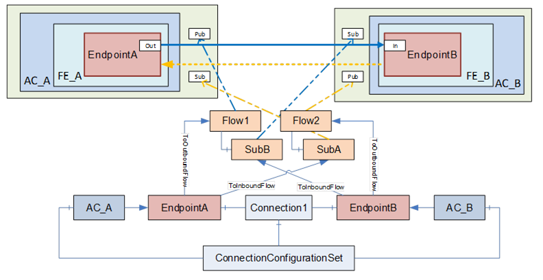
Figure E.12 – Unidirectional connection with heartbeat illustration
The Connection configuration for a unidirectional connection contains the following configuration information (see Figure E.13):
- EndpointA, indicating OutputVariables,
- EndpointB, indicating InputVariables,
- Flow1 and SubB describing the configuration for the information flow from EndpointA to EndpointB.
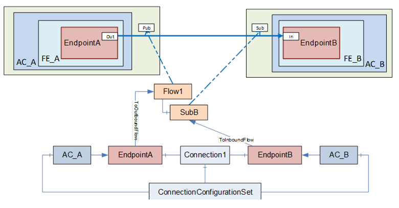
Figure E.13 – Unidirectional connection illustration
The Connection configuration for an autonomous publisher contains the following configuration information (see Figure E.14):
- EndpointA, indicating OutputVariables;
- Flow1, describing the configuration for the information flow from EndpointA to one or more unknown Subscribers.
For an autonomous publisher, no SubscriberConfiguration is required (see 6.13.3.2).
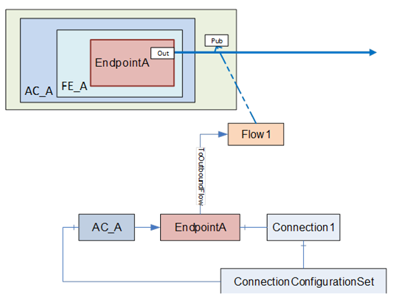
Figure E.14 – Autonomous publisher illustration
The Connection configuration for an autonomous subscriber contains the following configuration information (see Figure E.15):
- EndpointA, indicating InputVariables,
- Flow1 and SubA describing the configuration for the information flow from an unknown Publisher to EndpointA.
For an autonomous subscriber, no ToOutboundFlow Reference is required. Configuration, which applies only to the Publisher of the information flow, can be omitted, i.e., Address and TransmitQos (see E.4.1).
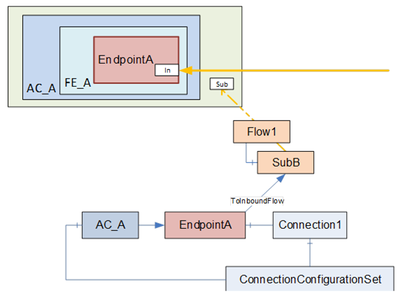
Figure E.15 – Autonomous subscriber illustration
This subclause provides an overview of PubSub communication options and the use of DataSets. For a complete description of PubSub communication, PubSub communication options, DataSets and DataSetMetaData, please see OPC 10000-14.
PubSub communication has multiple options that are defined by Profiles. To see what is defined in UAFX for a controller or device, see the UAFX-defined Profiles in the Profile database. When setting up communication between controllers, between a device and a controller, or even between devices, the engineering tool must ensure that the PubSub Profile to be used for the communication is available on the communicating devices. To ensure interoperability, the UAFX controller Profile require a specific PubSub Profile. Vendors are free to add additional PubSub Profiles.
At this point, UADP is required in UAFX Profiles, and thus, this discussion will focus on this communication protocol. Within a Profile, there are options related to the communication configuration. The engineering tools and/or ConnectionManager can make various selections. This can include optimisations which group multiple DataSetMessages into a single Network Message (see Figure E.16).
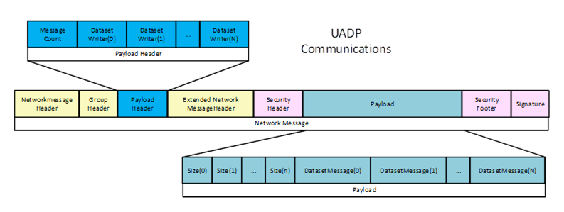
Figure E.16 – UADP network message overview
Many of the options are self-described in the UADP PubSub communication protocol, allowing a Subscriber to handle a larger range of published messages. The UADP communication includes header information that describes the overall DataSet. It can include information like a timestamp and/or status information (see Figure E.17).
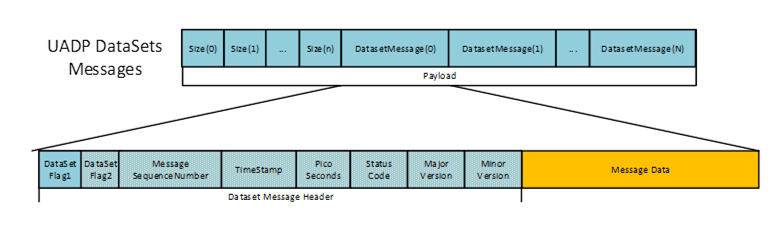
Figure E.17 – DataSetMessage header
The DataSetMessage can use the periodic fixed mapping, depending on the communication options selected. It is a fixed structure where all items defined in the DataSet have a value that is returned in every message. The message only contains the values, so the Subscriber has to be aware of the order/mapping of Variables in the DataSet (see Figure E.18). The encoding of the value is also configurable. The period fixed profile requires the encoding as a raw value. Other profiles support a variant encoding (which allows for a status to be sent in the case of a bad status) or a DataValue (value, status, and timestamps) encoding.
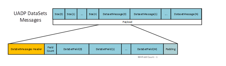
Figure E.18 – Fixed DataSetMessage
Other PubSub Profiles can include a dynamic layout. In this case, the DataSetMessage can also be a delta frame, which is very similar to Client Server communication, and only changed values are sent. In this type of DataSetMessage, an index and the value are packaged into the message. The index is only an index into the array of Variables defined in the DataSet (see Figure E.19).
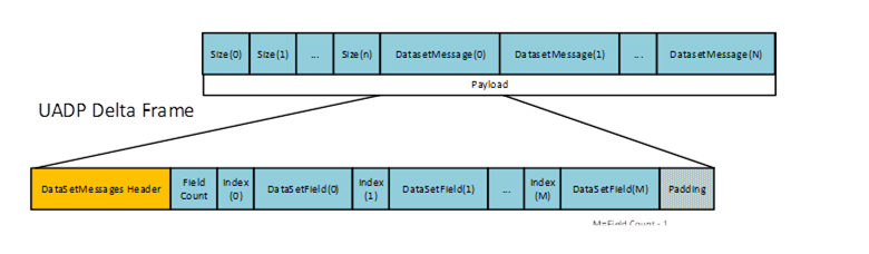
Figure E.19 – Delta frame DataSetMessage
The DataSetMessage can also be an Event. Events are much like fixed DataSetMessages, except that they are always a structure that is encoded as a Variant (see Figure E.20).
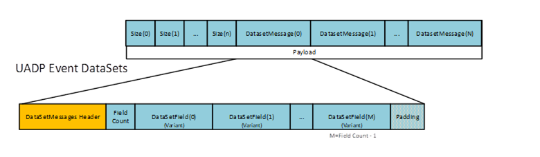
Figure E.20 – Event DataSet data
In this version of this document, Events are not used.
The configuration of a DataSet is defined as an array of structures, where the structure lists the details of the item that is to be published, and the array provides the order in which they will be in the DataSet. These DataSets could be preconfigured or could be created at run time. Figure E.21 illustrates what is defined as part of a DataSet (both Publisher and Subscriber).
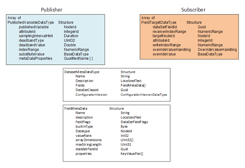
Figure E.21 – Dataset definition information
Preconfigured DataSets can be provided in UAFX as part of a FunctionalEntity or as part of an AutomationComponent.
For this version of the document, it is recommended to provide preconfigured DataSets as part of a FunctionalEntity. Use cases for DataSets as part of an AutomationComponent could be added in a later version of this document.
When establishing communication, the DataSet and the Publisher's DataSetMetaData define what is on the wire. This includes which Nodes are used for the Values, their DataTypes (on the wire and native), the size (if an array or string) and the possible pre-processing of the Values (filtering, error handling, etc.).
The DataSet definition on the Subscriber describes the mapping of fields in the DataSet to Variables in the Server. It includes error handling and allows for restricting the data field to a specific index in the field (fields that were arrays on the wire). The (Standalone-) SubscribedDataSet can select a subset of the transmitted fields, i.e., it can skip any values that it is not interested in.
In a ConnectionConfigurationSet, a specific Connection can use a preconfigured DataSet or dynamically create a DataSet for the Publisher or Subscriber. Regardless of whether the DataSet is preconfigured or dynamically configured, the important aspect for the engineering tool and the ConnectionManager is that the appropriate published Variable is mapped to the appropriate subscribed Variable. This also includes checking that the DataType of the Variables is correct (and matches) and that the engineering units or other metadata associated with the Variable also match (see 5.5.6.2.5).
The verification of metadata and DataSet can be minimised if the ConnectionEndpointParameter contains ExpectedPublishedDataSetVersion and/or ExpectedSubscribedDataSetVersion. These Variables can be used to confirm that the current configuration matches what was defined in the engineering tool.
Three possible combinations of DataSets exist for an information flow on a Connection between two FunctionalEntities to be configured:
- Preconfigured DataSets exist on both endpoints.
- A preconfigured DataSet exists on just one of the endpoints.
- Preconfigured DataSets do not exist on either endpoint.
For scenario (a), the engineering tool configuring the information flow uses the preconfigured DataSets.
NOTE A unidirectional Connection has one information flow. A bidirectional Connection consists of two information flows (see 5.5.1).
For scenario (b), the engineering tool configuring the information flow creates a customised DataSet with DataSetMetaData matching the preconfigured DataSet for the desired variables. The engineering tool should provide (as in scenario (a) the name of the preconfigured DataSet for one ConnectionEndpoint, but leave the name empty on the other ConnectionEndpoint.
For scenario (c), the engineering tool configuring the information flow creates customised DataSets with matching DataSetMetaData for both ConnectionEndpoints.
An engineering tool, or the ConnectionManager, could generate the PubSubConfiguration.
If the engineering tool generates the PubSubConfiguration, it will store customised DataSets within the PubSubConfiguration, e.g. PublishedDataSets in publishedDataSets and SubscribedDataSets as part of the DataSetReader. Preconfigured DataSets are used by setting the dataSetName in the DataSetWriter or DataSetReader.
If the ConnectionManager is intended to generate the PubSubConfiguration, the engineering tool would add the names of preconfigured DataSets to be used in the ConnectionEndpointConfigurationParameter (e.g., PreconfiguredPublishedDataSetName or PreconfiguredSubscribedDataSetName). Customised DataSets can be stored in the PublishedDataSetData or SubscribedDataSetData (see F.1.5) or within the vendor-specific download format.
A ConnectionConfigurationSet might contain multiple Connections that all need to communicate as a set. In this case, the ConnectionManager and/or the engineering tool can also optimise communication by grouping Variables for multiple Connections into a single DataSet or into a single network message. For example, if the ConnectionConfigurationSet has three Connections between two AutomationComponents (different FunctionalEntities), the PubSub configuration might be a single DataSet with all the required Variables. Alternatively, it might be three DataSets in a single network message. If more AutomationComponents are in the set, it might even be a multicast network message that multiple AutomationComponents could be subscribing to. Please refer to Clause 5.5.6.2 for further information.
The usage of SecurityGroups is defined by OPC 10000-14 as follows:
- The SKS is responsible for generating keys for its configured SecurityGroups. The SKS can expose the SecurityGroups in its Information Model.
- A Publisher uses the current key to sign or sign and encrypt NetworkMessages, and Subscriber(s) to authenticate or authenticate and decrypt NetworkMessages. The past key, current key and a requested number of future keys are distributed from the SKS to the Publisher and the Subscriber(s) using the push or pull model. How past, current and future keys are stored and organised on the Publisher and Subscriber(s) is vendor-specific.
In the push model, the set of keys is pushed by the SKS to the AutomationComponents using SetSecurityKeys. In the pull model, the set of keys is pulled by the AutomationComponents from the SKS using GetSecurityKeys.
The SecurityGroupId links the key generation side (i.e., the SKS) and the key usage side (i.e., Publisher, Subscriber). If an AutomationComponent calls GetSecurityKeys on the SKS or an SKS calls SetSecurityKeys on the AutomationComponent with a specific SecurityGroupId, all WriterGroups and DataSetReaders utilising the SecurityGroupId on the AutomationComponent will get the new set of keys.
PubSubKeyPushTargets are used on the SKS to manage the distribution of the keys for the push model. They have no equivalent on the key usage side. The SKS can expose the PubSubKeyPushTargets in its Information Model.
The SKS responsible for generating the security keys related to a ConnectionConfigurationSet is indicated in the ConnectionConfigurationSet by the SecurityKeyServer configuration. In addition, the SecurityKeyServer indicates whether to use the push or pull model for the distribution of the security keys.
Every UAFX implementation compliant with the “http://opcfoundation.org/UA-Profile/UAFX-Controller-Profile” supports the SKS push model. An AutomationComponent indicates support for the pull model by the Facets it includes in its ServerProfileArray (“http://opcfoundation.org/UA-Profile/Publisher/MessageSecurity” for a Publisher and “http://opcfoundation.org/UA-Profile/Subscriber/MessageSecurity” for a Subscriber). The ServerProfileArray can be retrieved online or from the Descriptor.
ConnectionManager and SKS could be located on the same Server. In this case, the ConnectionManager could use vendor-specific means to configure the SKS. If the ConnectionManager and SKS are located on different Servers, the SKS exposes its configuration model. A ConnectionManager could wish to optimise its communication with the external SKS. These examples illustrate this communication.
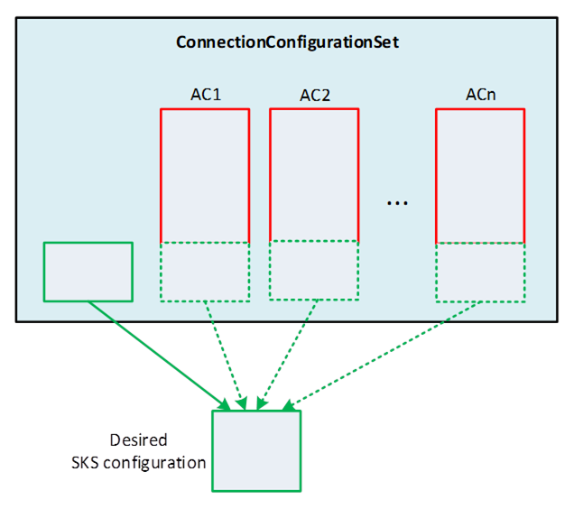
Figure E.22 – Building the desired configuration for the SKS
As illustrated in Figure E.22, the ConnectionManager constructs the desired configuration for the SKS from the set of SecurityGroups and PubSubKeyPushTargets in the ConnectionConfigurationSet Object and PubSubCommunicationModelConfigurations of all AutomationComponentConfigurations in the ConnectionConfigurationSet (see 6.16.3 and Figure E.6). It is recommended that only the ConnectionConfigurationSet Object is used for holding the desired SKS configuration.
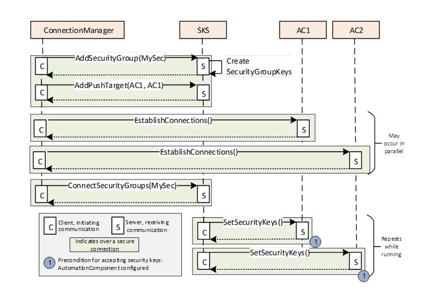
Figure E.23 – Updating the SKS to configure a push model
Figure E.23 illustrates the configuration of the SKS for the push model.
The ConnectionManager applies the desired configuration on the SKS:
- SecurityGroups are added to the SKS using AddSecurityGroup,
- PubSubKeyPushTargets are added to the SKS using AddPushTarget and ConnectSecurityGroups.
The SKS will not return an error if the SecurityGroup or the PubSubKeyPushTarget (with the same parameters) is added multiple times.
After the SKS configuration is finished, the SKS will start to periodically push the keys to the AutomationComponents registered with the push targets. A push target will accept keys only if they are from an SKS that is trusted and the SecurityGroupId is known. SecurityGroupIds (for a Publisher in the WriterGroup and for a Subscriber in the ReaderGroup/DataSetReader) are configured by the ConnectionManager on the AutomationComponent as part of the EstablishConnections Call. If a push target rejects SetSecurityKeys, the SKS will continue to retry at RetryInterval. If a push target accepts SetSecurityKeys, the SKS will repeat pushing keys at a period of half KeyLifetime (see OPC 10000-14).
For a push model configuration, it is recommended that the ConnectionManager establish the Connections on the AutomationComponents before updating the SKS. It is recommended to perform as much configuration as possible in parallel, which could mean that the SKS configuration completes before all of the Subscribers and Publishers are configured (each configuration is processed in a separate thread).
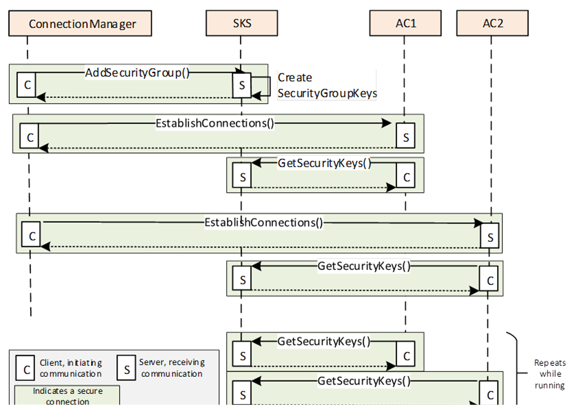
Figure E.24 – Updating the SKS to configure a pull model
Figure E.24 illustrates the configuration of the SKS for the pull model.
The ConnectionManager applies the desired configuration on the SKS:
- SecurityGroups are added to the SKS using AddSecurityGroup.
SecurityKeyServer and SecurityGroupIds (for a Publisher in the WriterGroup and for a Subscriber in the ReaderGroup/DataSetReader) are configured by the ConnectionManager on the AutomationComponent as part of the EstablishConnections Call. After the AutomationComponent configuration is finished, the Publisher/Subscriber periodically accesses the SKS and pulls keys. The Publisher/Subscriber would have to have Client capabilities. The SKS will return keys only if it trusts the Client making the connection, and the SecurityGroupId is known. The pull can be triggered on the Subscriber by the reception of a NetworkMessage using a new key from the Publisher. The Subscriber keeps a certain number of future keys, and when a new one is used by the Publisher, it is already cached and available.
For a pull model configuration, it is recommended that the ConnectionManager establish the Connections on the AutomationComponents after updating the SKS. If the SKS rejects GetSecurityKeys (e.g., SecurityGroups have not yet been added to the SKS), the next GetSecurityKeys is repeated by the AutomationComponent using vendor-specific retry logic.
It is important to understand that end-to-end communication will not occur until all parties (Publisher, Subscriber, and SKS) have been configured by the ConnectionManager and current keys have been distributed to Publishers and Subscribers. For the push model, the SKS continues to retry pushing keys using SetSecurityKeys at the RetryInterval if an AutomationComponent is not yet configured. For the pull model, the AutomationComponent continues to retry pulling keys using GetSecurityKeys using vendor-specific retry logic if the SKS is not yet configured. Retry intervals can affect how fast communication starts for a Connection. Typically, a retry interval should be short enough not to delay communication but not so short that it overloads network traffic or the Server. See OPC 10000-14 for additional details on SecurityKeyServices.
If using PubSub as a communication model, the ConnectionConfigurationSet contains a PubSubConfiguration Variable for each AutomationComponent’s CommunicationModelConfig that has a DataType that is a large structure. This structure is passed to the EstablishConnections Method to provide the required information to the AutomationComponent to configure PubSub communication on that AutomationComponent. An OPC UA Client could adjust some information that is inside this data structure (see 5.5.2). To facilitate this possible adjustment, some aspects of the large structure are exposed as Variables in the ConnectionConfigurationSet.
Figure E.25 illustrates the relation between elements in the ConnectionConfigurationSet and the PubSubConfiguration. Note that for clarity, parts of the ConnectionConfigurationSet are omitted. For an overview of all elements in the ConnectionConfigurationSet, please refer to 6.8.
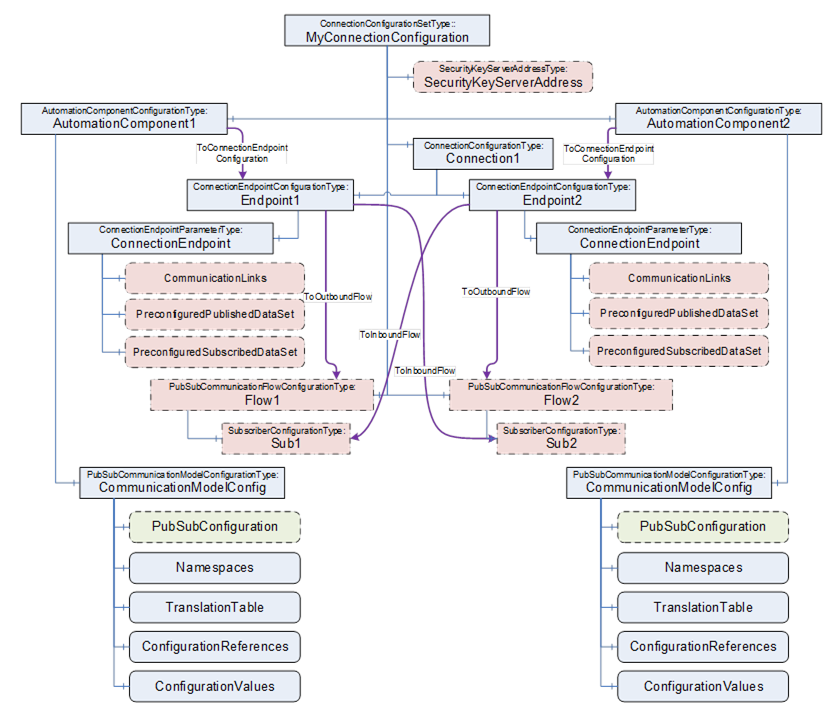
Figure E.25 – ConnectionConfigurationSet and PubSubConfiguration
Each AutomationComponentConfiguration listed in the ConnectionConfigurationSet has its individual PubSubCommunicationModelConfiguration. The PubSubCommunicationModelConfiguration holds the PubSubConfiguration (highlighted in green with a dashed line).
The following elements within the ConnectionConfigurationSet are related to the PubSubConfiguration (highlighted in red with dashed-dotted lines):
- ConnectionEndpointParameter Variables CommunicationLinks, PreconfiguredPublishedDataSet, and PreconfiguredSubscribedDataSet are related to DataSetReader and DataSetWriter in the PubSubConfiguration;
- PubSubCommunicationFlowConfiguration Object including its SubscriberConfiguration child Objects and SecurityKeyServerAddress Object, contain Variables related to PubSubConnections, ReaderGroups and WriterGroups in the PubSubConfiguration.
All of the related Variables are of SelectionListType, which allows limiting the choice that can be made (see 6.8.1). After a ConnectionConfigurationSet is edited (see 6.7.4), the ConnectionManager reflects the changes into the PubSubConfiguration.
The PubSubConfiguration could be generated by an engineering tool or by the ConnectionManager.
Clause E.6 indicates PubSubConfiguration settings, which are based on using UDP-UADP as the transport Profile and UADP-Periodic-Fixed as the header layout Profile. Details for other transport or header layout Profiles could be added in a later version of this document.
As defined in OPC 10000-14, a WriterGroup defines the Publisher of a NetworkMessage. It is recommended that the PubSubConfiguration contains a WriterGroup for each instance of PubSubCommunicationFlowConfigurationType. For the example illustrated in Figure E.5, a WriterGroup in AC_A is generated based on the parameters in Flow1, and a WriterGroup is generated for each AC_B and AC_C based on the parameters in Flow2.
Figure E.26 illustrates the relation between the PubSubCommunicationFlowConfiguration and the PubSubConnection and WriterGroup within the PubSubConfiguration. If any changes are made to the PubSubCommunicationFlowConfiguration, the related PubSubConnection information, as illustrated in Figure E.26, will be updated.
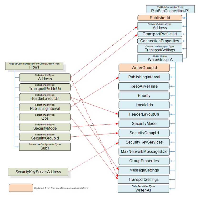
Figure E.26 – ConnectionConfigurationSet and WriterGroup
It is recommended to update WriterGroupId and PublisherId after issuing the ReserveCommunicationIdsCmd; see E.2 for details.
Depending on the transport profile and on the type of Address (unicast or multicast), the Address will be in the PubSubConnection or in the WriterGroup’s TransportSettings; see OPC 10000-14 for details. As an example, if UDP-UADP is used as the transport profile, a unicast address is set in the WriterGroup, but a multicast address is set in the PubSubConnection.
TransportProfileUri is used to set up the information in the PubSubConnection, whereas HeaderLayoutUri, PublishingInterval, Qos, SecurityMode and SecurityGroupId are used to set up the information in the WriterGroup.
The PubSubConnection elements ConnectionProperties and TransportSettings are transport-specific. For the TransportProfileUri “http://opcfoundation.org/UA-Profile/Transport/pubsub-udp-uadp” (UDP-UADP), both are set to null.
The WriterGroup elements GroupProperties and TransportSettings are transport-specific. For UDP-UADP, GroupProperties is set to null. For UDP-UADP, the elements MessageDelay, MessageRepeatCount, Address, QosCategory, and DatagramQos are defined in TransportSettings. The value of MessageDelay and MessageRepeatCount depends on the header layout. For HeaderLayoutUri “http://opcfoundation.org/UA/PubSub-Layouts/UADP-Periodic-Fixed” (UADP-Periodic-Fixed), both are set to 0. QosCategory and DatagramQos are derived from Qos.
The WriterGroup element MessageSettings is transport-specific. For UDP-UADP, the GroupVersion is defined by the generator of the ConnectionConfigurationSet. To ensure a consistent definition of the GroupVersion, it is recommended that the WriterGroup is configured completely within one ConnectionConfigurationSet. NetworkMessageContentMask and DataSetOrdering are derived from the HeaderLayoutUri. PublishingOffset and SamplingOffset can be set to a negative value, meaning not used. They could be used when additional Quality of Services are specified.
SecurityKeyServerAddress is set in the WriterGroup only if a pull model is to be configured (for additional details, see 9.3.2).
For MaxNetworkMessageSize, follow the recommendations in OPC 10000-14. For UADP-PeriodicFixed, KeepAliveTime should be set to PublishingInterval. LocaleIds can be set to a value different from null if the translation of Strings will be done by the Publisher. Priority can be used to set the relative priority of the WriterGroup for processing it.
As defined in OPC 10000-14, DataSetReaders in a ReaderGroup can extract their DataSetMessages from different NetworkMessages. However, it is recommended that the PubSubConfiguration generated for an AutomationComponent contains a ReaderGroup for each PubSubCommunicationFlowConfiguration. By this, common parameters (e.g., SecurityGroupId, SecurityKeyServices, TransportSettings, or MessageSettings) are configured on the ReaderGroup and do not need to be repeated in each DataSetReader.
For the example illustrated in Figure E.5, a ReaderGroup in AC_A is generated based on the parameters in SubA, a ReaderGroup is generated for each AC_B based on the parameters in SubB, and a ReaderGroup is generated in AC_C based on the parameters in SubC.
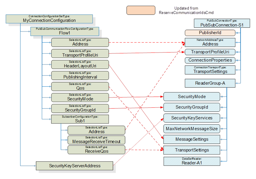
Figure E.27 – ConnectionConfigurationSet and ReaderGroup
Figure E.27 illustrates the relation between the SubscriberConfiguration and the PubSubConnection and ReaderGroup within the PubSubConfiguration.
It is recommended to update PublisherId after issuing the ReserveCommunicationIdsCmd; see E.2 for details.
For a Subscriber, the Address will be in the PubSubConnection. See 6.13.3.3 on how to set the Address.
TransportProfileUri is used to set up the information in the PubSubConnection, whereas HeaderLayoutUri, PublishingInterval, Qos, SecurityMode and SecurityGroupId are used to set up the information in the ReaderGroup.
The PubSubConnection elements ConnectionProperties and TransportSettings are transport-specific. For the UDP-UADP, both are set to null.
SecurityKeyServerAddress is set in the ReaderGroup only if a pull model is to be configured (for additional details, see 9.3.2).
For MaxNetworkMessageSize, follow the recommendations in OPC 10000-14.
As illustrated in Figure E.28, the configuration of the DataSetWriter can be derived from the ConnectionEndpointParameter and the PubSubCommunicationFlow.
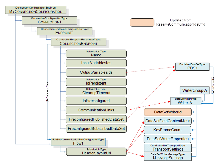
Figure E.28 – ConnectionConfigurationSet and DataSetWriter
The ToDataSetWriter Reference can be derived from either the PreconfiguredPublishedDataSet or from a custom PublishedDataSet within the PubSubConfiguration. The PublishedDataSet contains the OutputVariableIds specified in the ConnectionEndpointParameter.
The DataSetWriter element MessageSettings is transport-specific. For UDP-UADP, the DataSetMessageContentMask, ConfiguredSize, NetworkMessageNumber, and DataSetOffset are derived from the HeaderLayoutUri. For UADP-Periodic-Fixed ConfiguredSize, NetworkMessageNumber and DataSetOffset of the DataSetMessage are determined by the generator of the PubSubConfiguration.
For UADP-Periodic-Fixed, the KeyFrameCount is set to 1.
For UDP_UADP, no DataSetWriterProperties or TransportSettings are defined.
As illustrated in Figure E.29, the configuration of the DataSetReader can be derived from the ConnectionEndpointParameter, the SubscriberConfiguration and its parent Object.
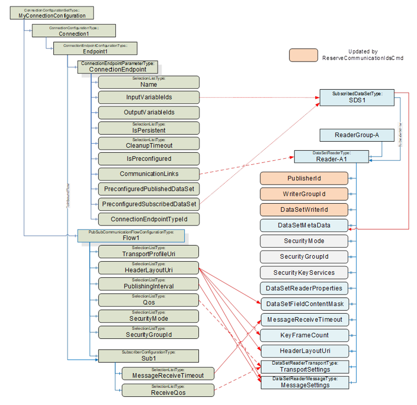
Figure E.29 – ConnectionConfigurationSet and DataSetReader
It is recommended to update PublisherId, WriterGroupId and DataSetWriterId after issuing the ReserveCommunicationIdsCmd; see E.2 for details. The values are set to correspond to the Publisher of the DataSetMessage.
The ToDataSetReader Reference can be derived from either the PreconfiguredSubscribedDataSet or from a custom SubscribedDataSet within the PubSubConfiguration. The SubscribedDataSet contains the InputVariableIds specified in the ConnectionEndpointParameter.
The DataSetReader element MessageSettings is transport-specific. For UDP-UADP, NetworkMessageNumber, DataSetOffset, NetworkMessageContentMask, and DataSetMessageContentMask are derived from the HeaderLayoutUri. For UADP-Periodic-Fixed, the NetworkMessageNumber and DataSetOffset of the DataSetMessage are determined by the generator of the PubSubConfiguration. ReceiveOffset and ProcessingOffset can be set to a negative value, indicating that they are not used. They will be used when additional Quality of Services are specified. GroupVersion and PublishingInterval are set corresponding to the Publisher of the DataSetMessage. DataSetClassId can be set to NULL.
The DataSetReader element TransportSettings is transport-specific. For UDP-UADP, the Address is set to NULL. QosCategory and DatagramQos are derived from ReceiveQos and Qos; see 6.13.3.3 for details.
For UDP_UADP, no DataSetReaderProperties are defined.
The ConnectionConfigurationSet can contain a PubSubConfiguration, which has a datatype of PubSubConfiguration2DataType. The PubSubConfiguration2DataType is a complex structure that can include DataSets (published or subscribed) that would include fields that are of NodeId DataType. NodeIds contain a NamespaceIndex. The NamespaceIndex is an index into a NamespaceArray that contains the URI that describes the owner of the Node. On a Server, this NamespaceArray is in the Server Object and is used to resolve all nodes on the Server. But in this case, the PublishedDataSet or SubscribedDataSet describes Variables that are on the Publisher or Subscriber Server, which is very likely to be a different Server. Depending on how the ConnectionConfigurationSet and PubSubConfiguration were generated, the Namespaces could not exist on the ConnectionManager Server.
This document describes how these NodeIds are to be resolved to the correct NamespaceIndex on the target Server before the structure is transmitted as part of an EstablishConnections (see 6.16.3.2). No issues exist in using the structure to set up a Connection, but if the configuration of the ConnectionManager Server is saved as a UANodeSet XML File or if the ConnectionConfigurationsSet is generated in an engineering tool and loaded into the ConnectionManager Server, problems could arise.
The general rules for processing the UANodeSet XML file are described in OPC 10000-6 Annex F.14. This clause provides the following instructions related to NodeIds:
“Variants can contain NodeIds, ExpandedNodeIds and QualifiedNames that must be modified, so the NamespaceIndexes and ServerIndexes reference the NamespaceUri and ServerUri tables in the UANodeSet.”
When generating a UANodeSet XML file, the NamespaceArray is included at the top of the UANodeset XML file. The NamespaceIndex could be updated to match the list of Namespaces listed at the top of the generated file. But in this case, not all Namespace entries might be defined in the ConnectionManager Server. So, exporting a UANodeset XML from the Server could result in an error (if the index in a Node does not exist in the Server’s NamespaceArray), or it could result in an incorrect Namespace being referenced. The simplest solution is to ensure that the ConnectionManager Server include all Namespaces in its NamespaceArray, even if the only Node using that Namespace is in the complex data structure.
When an engineering tool generates a ConnectionConfigurationSet, if it includes DataSets, then it will need to ensure that any NodeId it generates for its ConnectionManager’s Server does not have a translation issue. Multiple options exist:
- This could be done by ensuring that the ConnectionManager Server configuration includes all Namespaces used for all NodeIds, even if the NodeIds are not on the ConnectionManager’s Server.
- The ConnectionManager’s Server could understand the ConnectionConfigurationSet PubSubConfiguration and bypass standard processing for the PubSubConfiguration (i.e., not map).
- The engineering tool does not provide DataSets that include Variables, and the ConnectionManager generates the PubSubConfiguration.
The actual manner in which this is handled is vendor-specific, but the developer should be aware of these related issues.