This clause provides examples of functionality that a FunctionalEntity might expose. This includes Inputs, Outputs, ControlGroups and the resulting Connections. It will also describe the use of pre-configured DataSets and dynamically created DataSets.
In later clauses, these examples are linked to the Asset examples to provide a more complete picture.
The following types of References provided with this document and OPC 10000-23 are used for modelling FunctionalEntities:
- HasSubFunctionalEntity indicates that a FunctionalEntity has a nested FunctionalEntity.
- IsHostedBy indicates that a FunctionalEntity needs the referenced Asset to provide its functionality.
- IsExecutingOn relates a FunctionalEntity to the execution environment it is currently executing on (e.g., hardware component, task or thread).
- RepresentsSameEntityAs (symmetric) relates two entities which represent the same entity in the real world. This Reference can be used, for example, to relate a FunctionalEntity with its counterpart in the event of redundant logic. Another example might be a sensor that is dual-ported and wired to two different input signals. These two FunctionalEntities could be related with RepresentsSameEntityAs.
- RepresentsSameFunctionalityAs (symmetric) relates two entities representing the same functionality. This Reference can be used, for example, to relate a FunctionalEntity with its counterpart in a companion specification.
Figure D.17 provides an example FunctionalEntity model that could be applied to the single-board computer from the Asset example (MyRaspberryPi). The model shows a subtype of FunctionalEntityType that represents an execution engine that can run generic function blocks. The ExecutionEngineType includes the capability of loading libraries of function blocks, where each function block would be a FunctionalEntity. The model includes a Method that is used to load function block libraries and a Method to load a program that is executed by the ExecutionEngine. ExecutionEngineType will be used to illustrate various aspects of the FunctionalEntity model in the following clauses.
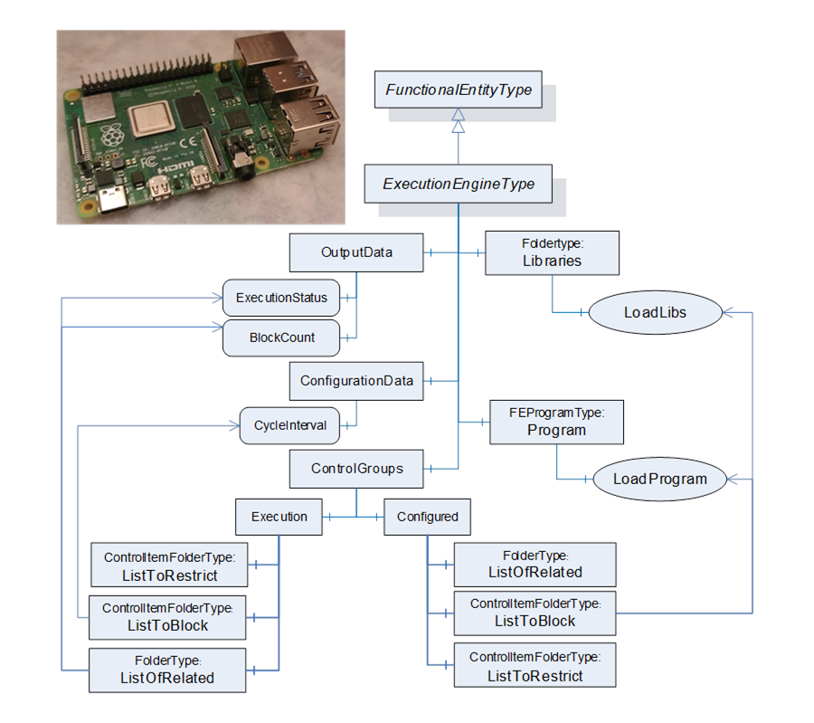
Figure D.17 – FunctionalEntity for MyRaspberryPi example
Figure D.18 provides an example of an instance of the ExecutionEngineType. It is empty in that no libraries or programs have been loaded. The model does show the AuthorUri for the ExecutionEngine (Http://Opcfoundation.org), an AuthorAssignedIdentifier (FLCEx01) and an AuthorAssignedVersion (1.0.0.0). The ApplicationIdentifier is set for the empty ExecutionEngine (ExecEngine01 with a program code of 26). The execution engine also has a default setting for BlockCount, 0 – it is empty. CycleInterval in milliseconds is 100. The status also indicates that nothing is loaded.
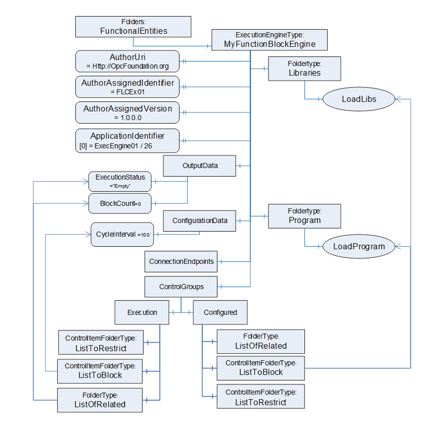
Figure D.18 – FunctionalEntity base instance example
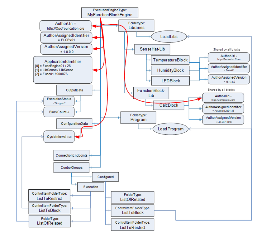
Figure D.19 illustrates an ExecutionEngine in which libraries have been loaded as well as a program. There are two libraries loaded. One that provides the functionality that comes with the SenseHat (note: not all functionality is illustrated) and another that provides calculation functions. These libraries can be thought of as a list of types that can be instantiated in programs. A program is also loaded, where the program is a sub-FunctionalEntity (MyApplicationProgram), and each execution block is represented by a separate FunctionalEntity (Temperature, Humidity, Calculation, and LED-Block).
Some key points in this example are that the ApplicationIdentifier has been updated for each application that was loaded since each was provided by a different vendor. The Sub FunctionalEntities all have their own AuthorUri and other properties, but they are not illustrated for simplicity. Also, each FunctionBlock has a list of inputs, outputs and configuration data that is also not illustrated. This illustration will be used in later clauses to illustrate other concepts.
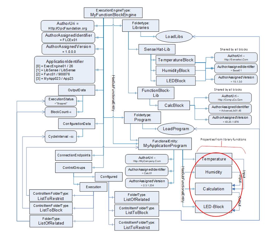
Figure D.19 – Example FunctionalEntities for RaspberryPi
InputData and OutputData can be modelled in various ways. The following clauses show examples of their usage. Figure D.20 illustrates the subtype of FunctionalEntityType that is used in the example. All items listed are mandatory in this subtype, but not all of these items will be shown in the examples to simplify the example figures. The AcmeAnalogueInputModuleType illustrates a hardware module that collects data from external input devices, where this information is made available to the controller. This AcmeAnalogueInputModuleType is external to the FunctionalEntity model; think of it as an existing Information Model. The FunctionalEntity then publishes this data to another controller, HMI, or even other devices as needed.
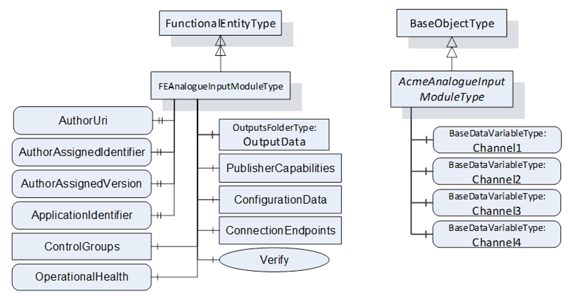
Figure D.20 – Example FunctionalEntity Type
The following examples illustrate how InputData and OutputData can be joined with DataSets. Consider, for example, an analogue input module with four channels plugged into one of the slots of the rack illustrated in D.2.3. The FunctionalEntity related to this Asset will provide OutputData only. To keep the following examples simple, ConfigurationData (e.g., measurement range and unit) is not shown. The dashed lines in the figures in this clause indicate “poor man’s references” instead of an actual Reference. The line will indicate if the poor man’s reference is using a NodeId or a Name.
The first variant, as illustrated in Figure D.21, assumes that the module can only exchange data using a preconfigured DataSet containing all four channels. In this case, a possible Information Model would organise the Variables in OutputData (the top-level folder). The preconfigured PublishedDataSet PDS_AI4 defines the fixed layout for the data exchange (indicated in PublisherCapabilities as one of the PreconfiguredPublishedDataSets). PreconfiguredDataSetOnly set to True indicates that the data contained in this folder can only be exchanged using the preconfigured PublishedDataSet.
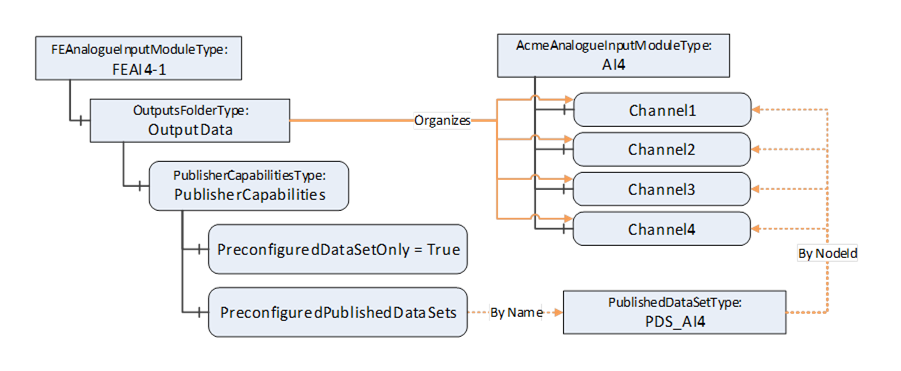
Figure D.21 – Sample for analogue input module – pre-configured DataSet only
This has the consequence that a ConnectionEndpoint established on that FunctionalEntity can only use the preconfigured PublishedDataSet for communication, as illustrated in Figure D.22. Conn_A and the PubSub Objects, including DSW_A (referencing the preconfigured PDS_AI4), are in this example created during EstablishConnections. For simplicity, PubSubConnection and WriterGroup are not shown.
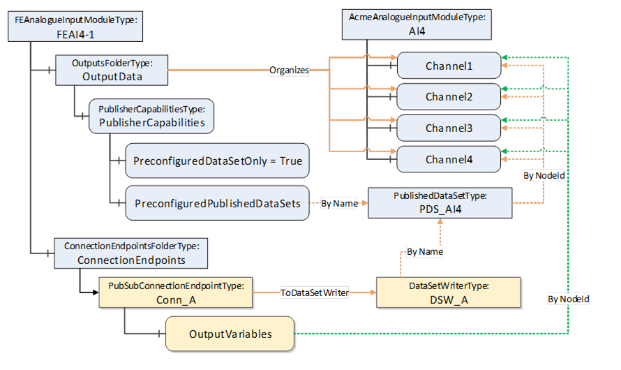
Figure D.22 – Fixed layout used by ConnectionEndpoint
The second variant assumes that the module can exchange data using a preconfigured DataSet containing all four channels, but also allows data to be exchanged using a customised DataSet (e.g., Channel2 and Channel3 to one controller and Channel1 to another controller).
In this case, a possible Information Model looks like the one illustrated in Figure D.23. However, PreconfiguredDataSetOnly set to False indicates that the data can be exchanged using the preconfigured PublishedDataSet, but in addition using a customised DataSet. A customised PublishedDataSet will be created during the establishment of a connection.
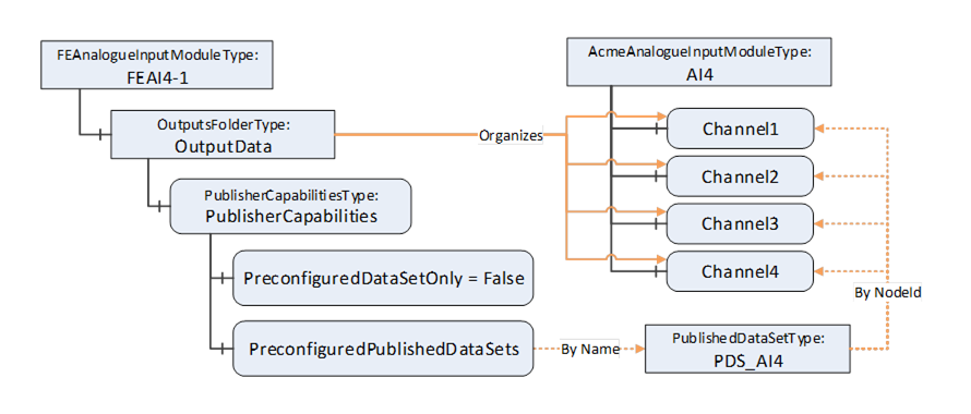
Figure D.23 – Sample for analogue input module – preconfigured and customised DataSet
ConnectionEndpoints established on that FunctionalEntity can use a preconfigured or customised DataSet as illustrated in Figure D.24. Conn_A, Conn_B, DSW_A, DSW_B and PDS_B are created in this example during EstablishConnections. ControllerA, connected through Conn_A, will receive all channels using the preconfigured PublishedDataSet PDS_AI4. ControllerB, connected through Conn_B, will receive Channel2 and Channel3 using the customised PublishedDataSet PDS_B.
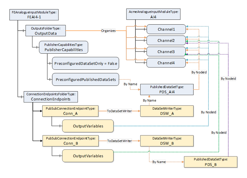
Figure D.24 – Preconfigured and customised DataSet used by ConnectionEndpoints
A third variant assumes that the module supports data exchange with customised DataSets only.
In this case, a possible Information Model looks like the one illustrated in Figure D.25. However, the absence of PreconfiguredPublishedDataSets indicates that only customised DataSets are supported.
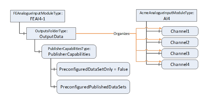
Figure D.25 – Sample for analogue input module – customised DataSets
Subfolders within the OutputData can be used, for example, to group data. Suppose that our sample module is an 8-channel input where a channel can be Int16 or Float. A possible Information Model is illustrated in Figure D.26.
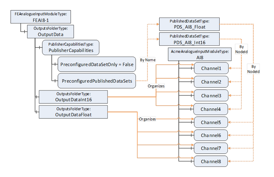
Figure D.26 – Sample for analogue input module – using groups
Again, as stated in the variants before, the module can choose to support preconfigured DataSets (e.g., one for all Int16 channels and one for all Float channels) and/or allow customised DataSets, depending on the setting of PreconfiguredDataSetOnly. A Connection can, for example, select Channel1 and Channel6. Figure D.27 illustrates this sample.
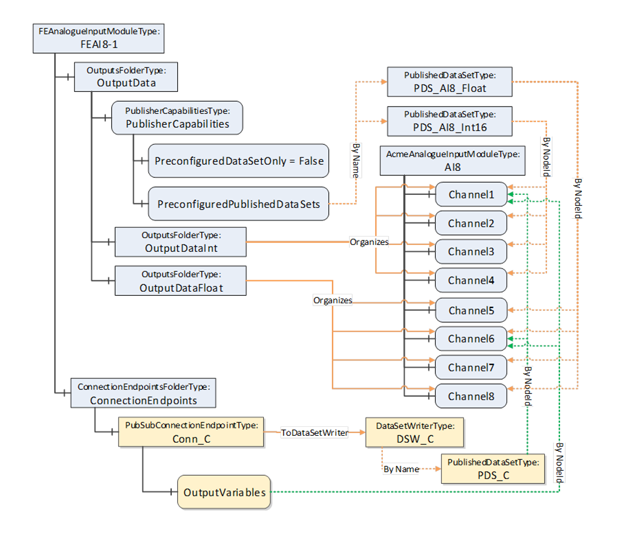
Figure D.27 – ConnectionEndpoint using grouped data
ControlGroups can be used for many purposes. They can illustrate related functionality or be used to establish control. Establishing control of a ControlGroup can be done by calling the Method EstablishControl or by using the EstablishControlCmd with the EstablishConnections Method. The following clauses provide examples of their usage.
Figure D.28 shows the FunctionalEntity for a simple temperature monitor based on the Raspberry Pi Sense HAT (see Figure D.5). The FunctionalEntity provides the output Variable Temperature, indicating the current temperature. It also includes a Variable EngineeringUnit (e.g., °C, °F, °K, …). This configuration variable allows the selection of the engineering unit for the Temperature.
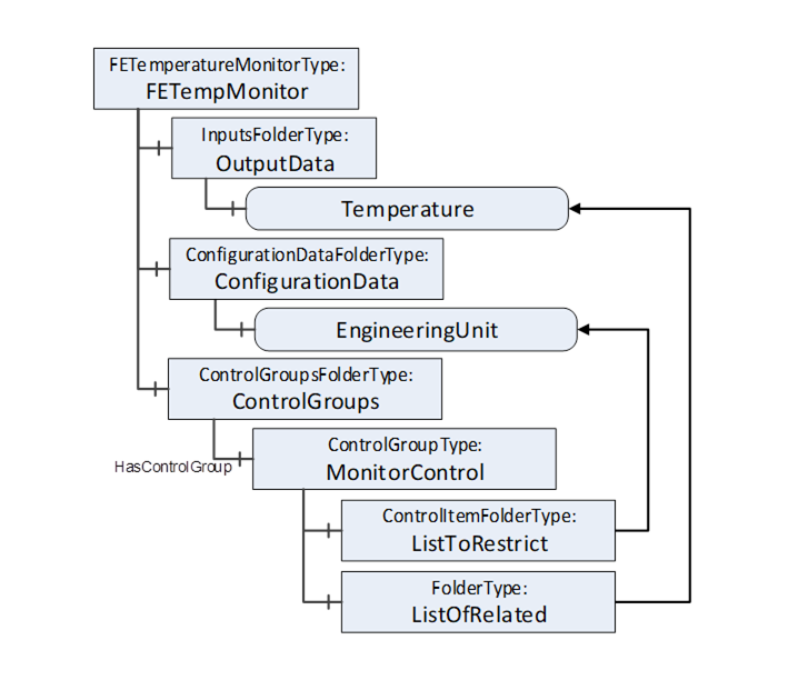
Figure D.28 – Sample FunctionalEntity for a simple temperature monitor
While using the Temperature, the EngineeringUnit for the Temperature should not change. To achieve this behaviour, the ControlGroup MonitorControl is provided. The EngineeringUnit is contained in the ListToRestrict to ensure that changes are restricted to the owner of the ControlGroup. Temperature is contained in the ListOfRelated to indicate that Temperature is part of the ControlGroup.
Assume that the Raspberry Pi (see D.2.2) is used for an automated guided vehicle (AGV) using the Sense HAT and some motors attached through the connectors. Figure D.29 illustrates a sample FunctionalEntity representing this simplified AGV.
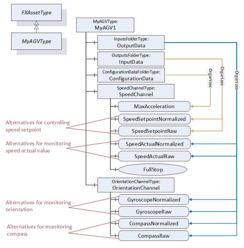
Figure D.29 – Sample FunctionalEntity for a simplified AGV
The Information Model offers two alternatives using a normalised value or raw data for controlling SpeedSetpoint and monitoring SpeedActual, Orientation, and Compass. Since both alternatives should not be used at the same time, two ControlGroups, ControlNormalized and ControlRaw, are added to the functional model (see Figure D.30).
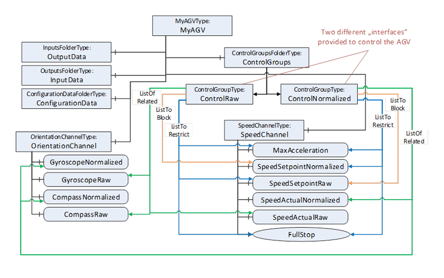
Figure D.30 – ControlGroups added to the functional model
Each of the ControlGroups represents an interface provided by the FunctionalEntity to control and monitor the AGV using normalised or raw data. The interface is represented by the ListToRestrict and ListOfRelated References. By this, the InputData, OutputData, ConfigurationData, and all provided Methods belonging to the interface can be easily determined. The ListToBlock prevents the setting of specific data, for example, SpeedSetpointNormalized, when controlling the AGV with raw data. The ListToRestrict prevents usage of the Method and setting of MaxAcceleration and SpeedSetpoint from anyone except the owner when controlling the AGV.
Since ControlNormalized and ControlRaw share Variables in their ListToRestrict, usage of them at the same time is only possible with the same owner.
ControlGroups can be used with Connections.
This example is an extension of the simple ControlGroup. Assume that the EngineeringUnit of Temperature (see Figure D.28) should not change during the lifetime of a Connection. A Connection configuration to achieve this behaviour would establish the control of MonitorControl using the EstablishControlCmd, set the EngineeringUnit with the desired unit (e.g., °F) using the SetConfigurationDataCmd, and reassign control to the ConnectionEndpoint using the ReassignControlCmd. Then, as long as the Connection is established, the EngineeringUnits are locked and cannot be changed.
ControlGroups can be used to expose functionality that is required to be used as a group. This example describes a pair of controllers that are part of a cascade control application (see Figure D.31). For a cascade control application, the PID controller is required to get feedback from the other controller as well as provide a setpoint to the other controller. This requires bidirectional communication.
In this example, Controller B comes with preconfigured DataSets, one for the Publisher and one for the Subscriber.
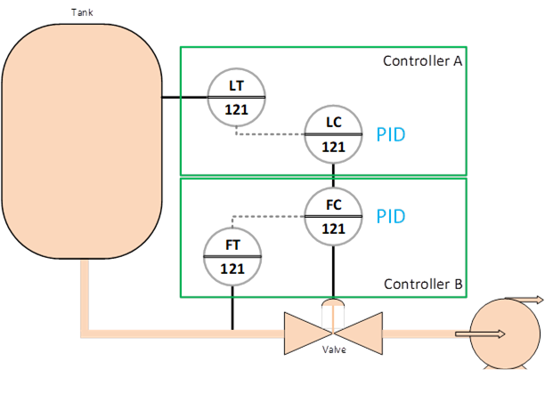
Figure D.31 – ControlGroup cascade Controller example
ControlGroup can be created to indicate that if using the PID in cascade mode, then the ControlGroup shall be used.
The communication between Controller A and Controller B could be set up by the ConnectionManager in Controller A, which would see the ControlGroup and would utilise the preconfigured Datasets that are described in the ControlGroup.
A Client is able to verify whether a FunctionalEntity meets the expectations of system engineering. This example demonstrates how to use verification.
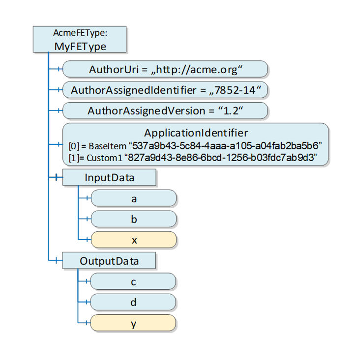
Figure D.32 – Sample for a FunctionalEntity
Figure D.32 illustrates a simple FunctionalEntity. The author defining the AcmeFEType provides mandatory input and output Variables (a, b, c, and d) and optional Variables x and y.
The author-defined type of a FunctionalEntity is uniquely identified by AuthorUri, AuthorAssignedIdentifier, and AuthorAssignedVersion. Therefore, a Client using the Verify Method can pass the following ExpectedVerificationVariables:
- PortableNodeIdentifier=“AuthorUri”, Value =“http://acme.org”
- PortableNodeIdentifier=“AuthorAssignedIdentifier”, Value =“7852-14”
- PortableNodeIdentifier=“AuthorAssignedVersion”, Value =“1.2”
Since the author decided to provide optional Variables, an instance of this type can or cannot provide x or y. To verify whether Variable x exists, a Client can pass the following ExpectedVerificationVariable:
- PortableNodeIdentifier=“x”, Value =null
The ApplicationIdentifier allows the identification of a specific instance of a FunctionalEntity and (if provided) any customisation by using a name (for user representation) and a unique ID (for verification). A sample for customisation is a drive or a process automation device that was configured by a specific engineering tool. A Client can pass the following ExpectedVerificationVariable:
- PortableNodeIdentifier=“ApplicationIdentifier”,[0] Value =“537a9b43-5c84-4aaa-a105-a04fab2ba5b6” [1] Value=“827a9d43-8e86-6bcd-1256-b03fdc7ab9d3”.
Figure D.33 illustrates other items that might be validated.
Relative paths can also be used for verifying the FunctionalEntity. For example, a Client can verify whether CalcBlock is provided by the correct AuthorUri or that a configuration variable is set to a correct value, as illustrated in Figure D.33.