
1 Scope
This document specifies a Companion Specification for organic coating technology - material supply systems.
A material supply system in this context can be any existing or future material supply system. The implicit and explicit information model specified by the material supply system Companion Specification will be defined as a UA companion specification using OPC UA constructs for the purpose of exchanging material supply system information with OPC UA applications. It defines the required data structures, parameters, methods, state machines etc. for the communication among material supply systems, between material supply systems and supporting systems and from material supply systems into higher level manufacturing systems (e.g. Manufacturing Execution System, MES), for information and diagnostic purposes and to set parameters regarding the material supply system operation.
2 Normative references
The following documents are referred to in the text in such a way that some or all of their content constitutes requirements of this document. For dated references, only the edition cited applies. For undated references, the latest edition of the referenced document (including any amendments and errata) applies
OPC 10000-1, OPC Unified Architecture - Part 1: Overview and Concepts
http://www.opcfoundation.org/documents/10000-1/
OPC 10000-2, OPC Unified Architecture - Part 2: Security Model
http://www.opcfoundation.org/documents/10000-2/
OPC 10000-3, OPC Unified Architecture - Part 3: Address Space Model
http://www.opcfoundation.org/documents/10000-3/
OPC 10000-4, OPC Unified Architecture - Part 4: Services
http://www.opcfoundation.org/documents/10000-4/
OPC 10000-5, OPC Unified Architecture - Part 5: Information Model
http://www.opcfoundation.org/documents/10000-5/
OPC 10000-6, OPC Unified Architecture - Part 6: Mappings
http://www.opcfoundation.org/documents/10000-6/
OPC 10000-7, OPC Unified Architecture - Part 7: Profiles
http://www.opcfoundation.org/documents/10000-7/
OPC 10000-8, OPC Unified Architecture - Part 8: Data Access
http://www.opcfoundation.org/documents/10000-8/
OPC 10000-100, OPC Unified Architecture - Part 100: Devices
http://www.opcfoundation.org/documents/10000-100/
OPC 10000-200, OPC Unified Architecture - Part 200: Industrial Automation
http://www.opcfoundation.org/documents/10000-200/
OPC 40001-1, OPC UA for Machinery - Part 1: Basic Building Blocks
http://www.opcfoundation.org/documents/40001-1/
OPC 30081, OPC UA for Process Automation Devices - PA-DIM
http://www.opcfoundation.org/documents/30081/
OPC 40001-2, OPC UA for Machinery - Part 2: Process Values
http://www.opcfoundation.org/documents/40001-2/
OPC 40700, OPC UA for Surface Technology - General Types
http://www.opcfoundation.org/documents/40700/
3 Terms, definitions and conventions
3.1 Overview
It is assumed that basic concepts of OPC UA information modelling are understood in this specification. This specification will use these concepts to describe the OPC UA for Surface Technology General Types Information Model. For the purposes of this document, the terms and definitions given in OPC 10000-1, OPC 10000-3, OPC 10000-4, OPC 10000-5, OPC 10000-7, OPC 10000-100, OPC 10000-200, OPC 40001-1 to 3, OPC 30081 and OPC 10031-4 as well as the following apply.
3.2 Abbreviated terms
| AC | Alarm and Condition |
| DCS | Distributed Control Systems |
| ERP | Enterprise Resource Planning |
| HMI | Human Machine Interface |
| HTTP | Hypertext Transfer Protocol |
| IP | Internet Protocol |
| MES | Manufacturing Execution System |
| PLC | Programable Logical Controller |
| PMS | Production Management System |
| TCP | Transmission Control Protocol |
| UML | Unified Modelling Language |
| URI | Uniform Resource Identifier |
| XML | Extensible Markup Language |
| OCT | Organic Coating Technology |
| ST | Surface Technology |
| MMS | Material Supply Systems |
| ST-OCT | Surface Technology - Organic Coating Technology |
| OCT-MSS | Organic Coating Technology - Material Supply Systems |
3.3 Conventions used in this document
3.3.1 Conventions for Node descriptions
3.3.1.1 Node definitions
Node definitions are specified using tables (see Table 2).
Attributes are defined by providing the Attribute name and a value, or a description of the value.
References are defined by providing the ReferenceType name, the BrowseName of the TargetNode and its NodeClass.
If the TargetNode is a component of the Node being defined in the table the Attributes of the composed Node are defined in the same row of the table.
The DataType is only specified for Variables; "[<number>]" indicates a single-dimensional array, for multi-dimensional arrays the expression is repeated for each dimension (e.g. [2][3] for a two-dimensional array). For all arrays the ArrayDimensions is set as identified by <number> values. If no <number> is set, the corresponding dimension is set to 0, indicating an unknown size. If no number is provided at all the ArrayDimensions can be omitted. If no brackets are provided, it identifies a scalar DataType and the ValueRank is set to the corresponding value (see OPC 10000-3). In addition, ArrayDimensions is set to null or is omitted. If it can be Any or ScalarOrOneDimension, the value is put into "{<value>}", so either "{Any}" or "{ScalarOrOneDimension}" and the ValueRank is set to the corresponding value (see OPC 10000-3) and the ArrayDimensions is set to null or is omitted. Examples are given in Table 1.
| Notation | DataType | ValueRank | ArrayDimensions | Description |
| 0:Int32 | 0:Int32 | -1 | omitted or null | A scalar Int32. |
| 0:Int32[] | 0:Int32 | 1 | omitted or {0} | Single-dimensional array of Int32 with an unknown size. |
| 0:Int32[][] | 0:Int32 | 2 | omitted or {0,0} | Two-dimensional array of Int32 with unknown sizes for both dimensions. |
| 0:Int32[3][] | 0:Int32 | 2 | {3,0} | Two-dimensional array of Int32 with a size of 3 for the first dimension and an unknown size for the second dimension. |
| 0:Int32[5][3] | 0:Int32 | 2 | {5,3} | Two-dimensional array of Int32 with a size of 5 for the first dimension and a size of 3 for the second dimension. |
| 0:Int32{Any} | 0:Int32 | -2 | omitted or null | An Int32 where it is unknown if it is scalar or array with any number of dimensions. |
| 0:Int32{ScalarOrOneDimension} | 0:Int32 | -3 | omitted or null | An Int32 where it is either a single-dimensional array or a scalar. |
The TypeDefinition is specified for Objects and Variables.
The TypeDefinition column specifies a symbolic name for a NodeId, i.e. the specified Node points with a HasTypeDefinition Reference to the corresponding Node.
The ModellingRule of the referenced component is provided by specifying the symbolic name of the rule in the ModellingRule column. In the AddressSpace, the Node shall use a HasModellingRule Reference to point to the corresponding ModellingRule Object.
If the NodeId of a DataType is provided, the symbolic name of the Node representing the DataType shall be used.
Note that if a symbolic name of a different namespace is used, it is prefixed by the NamespaceIndex (see 3.3.2.2).
Nodes of all other NodeClasses cannot be defined in the same table; therefore only the used ReferenceType, their NodeClass and their BrowseName are specified. A reference to another part of this document points to their definition. Table 2 illustrates the table. If no components are provided, the DataType, TypeDefinition and ModellingRule columns may be omitted and only a Comment column is introduced to point to the Node definition.
Each Type Node or well-known Instance Node defined shall have one or more ConformanceUnits defined in 8.1 that require the Node to be in the AddressSpace.
The relations between Nodes and ConformanceUnits are defined at the end of the tables defining Nodes, one row per ConformanceUnit. The ConformanceUnits are reflected in the Category element for the Node definition in the UANodeSet (see OPC 10000-6).
The list of ConformanceUnits in the UANodeSet allows Servers to optimize resource consumption by using a list of supported ConformanceUnits to select a subset of the Nodes in an Information Model.
When a Node is selected in this way, all dependencies implied by the References are also selected.
Dependencies exist if the Node is the source of HasTypeDefinition, HasInterface, HasAddIn or any HierarchicalReference. Dependencies also exist if the Node is the target of a HasSubtype Reference. For Variables and VariableTypes, the value of the DataType Attribute is a dependency. For DataType Nodes, any DataTypes referenced in the DataTypeDefinition Attribute are also dependencies.
For additional details see OPC 10000-5.
| Attribute | Value | ||||
| Attribute name | Attribute value. If it is an optional Attribute that is not set "--" will be used. | ||||
| References | NodeClass | BrowseName | DataType | TypeDefinition | Other |
|---|---|---|---|---|---|
| ReferenceType name | NodeClass of the target Node. | BrowseName of the target Node. | DataType of the referenced Node, only applicable for Variables. | TypeDefinition of the referenced Node, only applicable for Variables and Objects. | Additional characteristics of the TargetNode such as the ModellingRule or AccessLevel. |
| NOTE Notes referencing footnotes of the table content. | |||||
| Conformance Units | |||||
|---|---|---|---|---|---|
| Name of ConformanceUnit, one row per ConformanceUnit |
Components of Nodes can be complex that is containing components by themselves. The TypeDefinition, NodeClass and DataType can be derived from the type definitions, and the symbolic name can be created as defined in 3.3.3.1. Therefore, those containing components are not explicitly specified; they are implicitly specified by the type definitions.
The Other column defines additional characteristics of the Node. Examples of characteristics that can appear in this column are show in Table 3.
| Name | Short Name | Description |
| 0:Mandatory | M | The Node has the Mandatory ModellingRule. |
| 0:Optional | O | The Node has the Optional ModellingRule. |
| 0:MandatoryPlaceholder | MP | The Node has the MandatoryPlaceholder ModellingRule. |
| 0:OptionalPlaceholder | OP | The Node has the OptionalPlaceholder ModellingRule. |
| ReadOnly | RO | The Node AccessLevel has the CurrentRead bit set but not the CurrentWrite bit. |
| ReadWrite | RW | The Node AccessLevel has the CurrentRead and CurrentWrite bits set. |
| WriteOnly | WO | The Node AccessLevel has the CurrentWrite bit set but not the CurrentRead bit. |
If multiple characteristics are defined they are separated by commas. The name or the short name may be used.
3.3.1.2 Additional References
To provide information about additional References, the format as shown in Table 4 is used.
| SourceBrowsePath | Reference Type | Is Forward | TargetBrowsePath |
| SourceBrowsePath is always relative to the TypeDefinition. Multiple elements are defined as separate rows of a nested table. | ReferenceType name | True = forward Reference | TargetBrowsePath points to another Node, which can be a well-known instance or a TypeDefinition. You can use BrowsePaths here as well, which is either relative to the TypeDefinition or absolute. If absolute, the first entry needs to refer to a type or well-known instance, uniquely identified within a namespace by the BrowseName. |
References can be to any other Node.
3.3.1.3 Additional sub-components
To provide information about sub-components, the format as shown in Table 5 is used.
| BrowsePath | Reference | NodeClass | BrowseName | DataType | TypeDefinition | Others |
| BrowsePath is always relative to the TypeDefinition. Multiple elements are defined as separate rows of a nested table | NOTE Same as for Table 2 | |||||
3.3.1.4 Additional Attribute values
The type definition table provides columns to specify the values for required Node Attributes for InstanceDeclarations. To provide information about additional Attributes, the format as shown in Table 6 is used.
| BrowsePath | <Attribute name> Attribute |
| BrowsePath is always relative to the TypeDefinition. Multiple elements are defined as separate rows of a nested table | The values of attributes are converted to text by adapting the reversible JSON encoding rules defined in OPC 10000-6. If the JSON encoding of a value is a JSON string or a JSON number then that value is entered in the value field. Double quotes are not included. If the DataType includes a NamespaceIndex (QualifiedNames, NodeIds or ExpandedNodeIds) then the notation used for BrowseNames is used. If the value is an Enumeration the name of the enumeration value is entered. If the value is a Structure then a sequence of name and value pairs is entered. Each pair is followed by a newline. The name is followed by a colon. The names are the names of the fields in the DataTypeDefinition. If the value is an array of non-structures then a sequence of values is entered where each value is followed by a newline. If the value is an array of Structures or a Structure with fields that are arrays or with nested Structures then the complete JSON array or JSON object is entered. |
There can be multiple columns to define more than one Attribute.
3.3.2 NodeIds and BrowseNames
3.3.2.1 NodeIds
The NodeIds of all Nodes described in this standard are only symbolic names. Annex A defines the actual NodeIds.
The symbolic name of each Node defined in this document is its BrowseName, or, when it is part of another Node, the BrowseName of the other Node, a ".", and the BrowseName of itself. In this case "part of" means that the whole has a HasProperty or HasComponent Reference to its part. Since all Nodes not being part of another Node have a unique name in this document, the symbolic name is unique.
The NamespaceUri for all NodeIds defined in this document is defined in Annex A. The NamespaceIndex for this NamespaceUri is vendor-specific and depends on the position of the NamespaceUri in the server namespace table.
Note that this document not only defines concrete Nodes, but also requires that some Nodes shall be generated, for example one for each Session running on the Server. The NodeIds of those Nodes are Server-specific, including the namespace. But the NamespaceIndex of those Nodes cannot be the NamespaceIndex used for the Nodes defined in this document, because they are not defined by this document but generated by the Server.
3.3.2.2 BrowseNames
The text part of the BrowseNames for all Nodes defined in this document is specified in the tables defining the Nodes. The NamespaceUri for all BrowseNames defined in this document is defined in 9.2.
For InstanceDeclarations of NodeClass Object and Variable that are placeholders (OptionalPlaceholder and MandatoryPlaceholder ModellingRule), the BrowseName and the DisplayName are enclosed in angle brackets (<>) as recommended in OPC 10000-3.
If the BrowseName is not defined by this document, a namespace index prefix is added to the BrowseName (e.g., prefix '0' leading to '0:EngineeringUnits' or prefix '2' leading to '2:DeviceRevision'). This is typically necessary if a Property of another specification is overwritten or used in the OPC UA types defined in this document. Table 53 provides a list of namespaces and their indexes as used in this document.
3.3.3 Common Attributes
3.3.3.1 General
The Attributes of Nodes, their DataTypes and descriptions are defined in OPC 10000-3. Attributes not marked as optional are mandatory and shall be provided by a Server. The following tables define if the Attribute value is defined by this specification or if it is server-specific.
For all Nodes specified in this specification, the Attributes named in Table 7 shall be set as specified in the table.
| Attribute | Value |
| DisplayName | The DisplayName is a LocalizedText. Each server shall provide the DisplayName identical to the BrowseName of the Node for the LocaleId "en". Whether the server provides translated names for other LocaleIds is server-specific. |
| Description | Optionally a server-specific description is provided. |
| NodeClass | Shall reflect the NodeClass of the Node. |
| NodeId | The NodeId is described by BrowseNames as defined in 3.3.2.1. |
| WriteMask | Optionally the WriteMask Attribute can be provided. If the WriteMask Attribute is provided, it shall set all non-server-specific Attributes to not writable. For example, the Description Attribute may be set to writable since a Server may provide a server-specific description for the Node. The NodeId shall not be writable, because it is defined for each Node in this specification. |
| UserWriteMask | Optionally the UserWriteMask Attribute can be provided. The same rules as for the WriteMask Attribute apply. |
| RolePermissions | Optionally server-specific role permissions can be provided. |
| UserRolePermissions | Optionally the role permissions of the current Session can be provided. The value is server-specifc and depend on the RolePermissions Attribute (if provided) and the current Session. |
| AccessRestrictions | Optionally server-specific access restrictions can be provided. |
3.3.3.2 Objects
For all Objects specified in this specification, the Attributes named in Table 8 shall be set as specified in the table. The definitions for the Attributes can be found in OPC 10000-3.
| Attribute | Value |
| EventNotifier | Whether the Node can be used to subscribe to Events or not is server-specific. |
3.3.3.3 Variables
For all Variables specified in this specification, the Attributes named in Table 9 shall be set as specified in the table. The definitions for the Attributes can be found in OPC 10000-3.
| Attribute | Value |
| MinimumSamplingInterval | Optionally, a server-specific minimum sampling interval is provided. |
| AccessLevel | The access level for Variables used for type definitions is server-specific, for all other Variables defined in this specification, the access level shall allow reading; other settings are server-specific. |
| UserAccessLevel | The value for the UserAccessLevel Attribute is server-specific. It is assumed that all Variables can be accessed by at least one user. |
| Value | For Variables used as InstanceDeclarations, the value is server-specific; otherwise it shall represent the value described in the text. |
| ArrayDimensions | If the ValueRank does not identify an array of a specific dimension (i.e. ValueRank <= 0) the ArrayDimensions can either be set to null or the Attribute is missing. This behaviour is server-specific. If the ValueRank specifies an array of a specific dimension (i.e. ValueRank > 0) then the ArrayDimensions Attribute shall be specified in the table defining the Variable. |
| Historizing | The value for the Historizing Attribute is server-specific. |
| AccessLevelEx | If the AccessLevelEx Attribute is provided, it shall have the bits 8, 9, and 10 set to 0, meaning that read and write operations on an individual Variable are atomic, and arrays can be partly written. |
3.3.3.4 VariableTypes
For all VariableTypes specified in this specification, the Attributes named in Table 10 shall be set as specified in the table. The definitions for the Attributes can be found in OPC 10000-3.
| Attributes | Value |
| Value | Optionally a server-specific default value can be provided. |
| ArrayDimensions | If the ValueRank does not identify an array of a specific dimension (i.e. ValueRank <= 0) the ArrayDimensions can either be set to null or the Attribute is missing. This behaviour is server-specific. If the ValueRank specifies an array of a specific dimension (i.e. ValueRank > 0) then the ArrayDimensions Attribute shall be specified in the table defining the VariableType. |
3.3.3.5 Methods
For all Methods specified in this specification, the Attributes named in Table 11 shall be set as specified in the table. The definitions for the Attributes can be found in OPC 10000-3.
| Attributes | Value |
| Executable | All Methods defined in this specification shall be executable (Executable Attribute set to "True"), unless it is defined differently in the Method definition. |
| UserExecutable | The value of the UserExecutable Attribute is server-specific. It is assumed that all Methods can be executed by at least one user. |
3.3.4 Structures
OPC 10000-3 differentiates between different kinds of Structures. The following conventions explain, how these Structures shall be defined.
The first kind are Structures without optional fields where none of the fields allows subtype (except fields with abstract DataTypes). Its definition is in Table 12.
| Name | Type | Description |
| <someStructure> | structure | Subtype of <someParentStructure> defined in … |
SP1 | 0:Byte[] | Setpoint 1 |
SP2 | 0:Byte[] | Setpoint 2 |
The second kind are Structures with optional fields where none of the fields allows subtypes (except fields with abstract DataTypes). Its definition is in Table 13.
Structures with fields that are optional have an "Optional" column. Fields that are optional have True set, otherwise False.
| Name | Type | Description | Optional |
| <someStructure> | structure | Subtype of <someParentStructure> defined in … | |
SP1 | 0:Byte[] | Setpoint 1 | False |
SP2 | 0:Byte[] | Setpoint 2 | True |
The third kind are Structures without optional fields where one or more of the fields allow subtypes. Its definition is in Table 14.
Structures with fields that allow subtypes have an "Allow Subtypes" column. Fields that allow subtypes have True set, otherwise False. Fields with abstract DataTypes can always be subtyped.
| Name | Type | Description | Allow SubTypes |
| <someStructure> | structure | Subtype of <someParentStructure> defined in … | |
SP1 | 0:Byte[] | Setpoint 1 | False |
Allow Subtypes | 0:ByteString | Some Bytestring | True |
4 General information to ST - OCT - Material Supply Systems and OPC UA
4.1 Introduction to OCT and Material Supply Systems
Organic coating technology is used to apply organic coating material (e.g. liquid paint, coating powder, glue) to a surface. Organic coating technology is widely used in the producing industries. Organic coating technology can, depending on the process to be performed, consist of a variety of different types of machines (e.g. cleaning and pretreatment machinery, material supply systems, dosing systems, application systems, spray booths, dip coating, dryers). The information model covers materials supply systems and their specific machine components.
A material supply system is a comprehensive technical system for preparation (mixing, pressurizing, heating/cooling, etc.), transport, circulation, supply, dosing and provision of the liquid, powder or hybrid organic coating material to the application system. Machinery parts are the material supply unit for material preparation, circulation and supply and the dosing unit. The machinery supplies material to automated and manual application processes.
4.2 Introduction to OPC Unified Architecture
4.2.1 What is OPC UA?
OPC UA is an open and royalty free set of standards designed as a universal communication protocol. While there are numerous communication solutions available, OPC UA has key advantages:
A state of art security model (see OPC 10000-2).
A fault tolerant communication protocol.
An information modelling framework that allows application developers to represent their data in a way that makes sense to them.
OPC UA has a broad scope which delivers for economies of scale for application developers. This means that a larger number of high-quality applications at a reasonable cost are available. When combined with semantic models such as Material Supply Systems, OPC UA makes it easier for end users to access data via generic commercial applications.
The OPC UA model is scalable from small devices to ERP systems. OPC UA Servers process information locally and then provide that data in a consistent format to any application requesting data - ERP, MES, PMS, Maintenance Systems, HMI, Smartphone or a standard Browser, for examples. For a more complete overview see OPC 10000-1.
4.2.2 Basics of OPC UA
As an open standard, OPC UA is based on standard internet technologies, like TCP/IP, HTTP, Web Sockets.
As an extensible standard, OPC UA provides a set of Services (see OPC 10000-4) and a basic information model framework. This framework provides an easy manner for creating and exposing vendor defined information in a standard way. More importantly all OPC UA Clients are expected to be able to discover and use vendor-defined information. This means OPC UA users can benefit from the economies of scale that come with generic visualization and historian applications. This specification is an example of an OPC UA Information Model designed to meet the needs of developers and users.
OPC UA Clients can be any consumer of data from another device on the network to browser based thin clients and ERP systems. The full scope of OPC UA applications is shown in Figure 1.
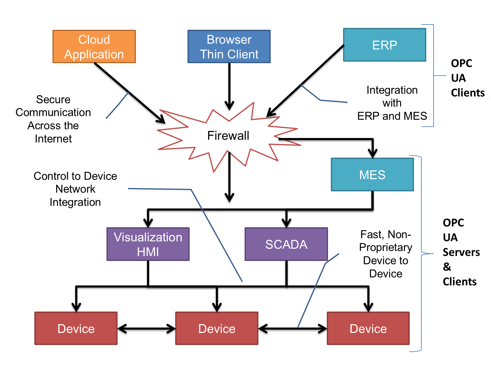
OPC UA provides a robust and reliable communication infrastructure having mechanisms for handling lost messages, failover, heartbeat, etc. With its binary encoded data, it offers a high-performing data exchange solution. Security is built into OPC UA as security requirements become more and more important especially since environments are connected to the office network or the internet and attackers are starting to focus on automation systems.
4.2.3 Information modelling in OPC UA
4.2.3.1 Concepts
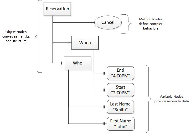
OPC UA provides a framework that can be used to represent complex information as Objects in an AddressSpace which can be accessed with standard services. These Objects consist of Nodes connected by References. Different classes of Nodes convey different semantics. For example, a Variable Node represents a value that can be read or written. The Variable Node has an associated DataType that can define the actual value, such as a string, float, structure etc. It can also describe the Variable value as a variant. A Method Node represents a function that can be called. Every Node has a number of Attributes including a unique identifier called a NodeId and non-localized name called as BrowseName. An Object representing a 'Reservation' is shown in Figure 2.
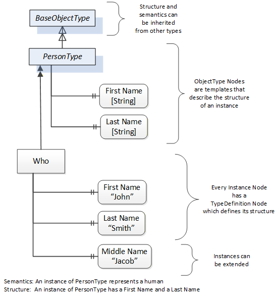
Object and Variable Nodes represent instances and they always reference a TypeDefinition (ObjectType or VariableType) Node which describes their semantics and structure. Figure 3 illustrates the relationship between an instance and its TypeDefinition.
The type Nodes are templates that define all of the children that can be present in an instance of the type. In the example in Figure 3 the PersonType ObjectType defines two children: First Name and Last Name. All instances of PersonType are expected to have the same children with the same BrowseNames. Within a type the BrowseNames uniquely identify the children. This means Client applications can be designed to search for children based on the BrowseNames from the type instead of NodeIds. This eliminates the need for manual reconfiguration of systems if a Client uses types that multiple Servers implement.
OPC UA also supports the concept of sub-typing. This allows a modeller to take an existing type and extend it. There are rules regarding sub-typing defined in OPC 10000-3, but in general they allow the extension of a given type or the restriction of a DataType. For example, the modeller may decide that the existing ObjectType in some cases needs an additional Variable. The modeller can create a subtype of the ObjectType and add the Variable. A Client that is expecting the parent type can treat the new type as if it was of the parent type. Regarding DataTypes, subtypes can only restrict. If a Variable is defined to have a numeric value, a sub type could restrict it to a float.
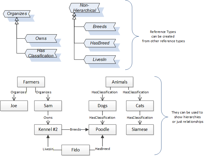
References allow Nodes to be connected in ways that describe their relationships. All References have a ReferenceType that specifies the semantics of the relationship. References can be hierarchical or non-hierarchical. Hierarchical references are used to create the structure of Objects and Variables. Non-hierarchical are used to create arbitrary associations. Applications can define their own ReferenceType by creating subtypes of an existing ReferenceType. Subtypes inherit the semantics of the parent but may add additional restrictions. Figure 4 depicts several References, connecting different Objects.
The figures above use a notation that was developed for the OPC UA specification. The notation is summarized in Figure 5. UML representations can also be used; however, the OPC UA notation is less ambiguous because there is a direct mapping from the elements in the figures to Nodes in the AddressSpace of an OPC UA Server.
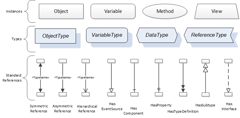
A complete description of the different types of Nodes and References can be found in OPC 10000-3 and the base structure is described in OPC 10000-5.
OPC UA specification defines a very wide range of functionality in its basic information model. It is not required that all Clients or Servers support all functionality in the OPC UA specifications. OPC UA includes the concept of Profiles, which segment the functionality into testable certifiable units. This allows the definition of functional subsets (that are expected to be implemented) within a companion specification. The Profiles do not restrict functionality, but generate requirements for a minimum set of functionality (see OPC 10000-7)
4.2.3.2 Namespaces
OPC UA allows information from many different sources to be combined into a single coherent AddressSpace. Namespaces are used to make this possible by eliminating naming and id conflicts between information from different sources. Each namespace in OPC UA has a globally unique string called a NamespaceUri which identifies a naming authority and a locally unique integer called a NamespaceIndex, which is an index into the Server's table of NamespaceUris. The NamespaceIndex is unique only within the context of a Session between an OPC UA Client and an OPC UA Server- the NamespaceIndex can change between Sessions and still identify the same item even though the NamespaceUri's location in the table has changed. The Services defined for OPC UA use the NamespaceIndex to specify the Namespace for qualified values.
There are two types of structured values in OPC UA that are qualified with NamespaceIndexes: NodeIds and QualifiedNames. NodeIds are locally unique (and sometimes globally unique) identifiers for Nodes. The same globally unique NodeId can be used as the identifier in a node in many Servers - the node's instance data may vary but its semantic meaning is the same regardless of the Server it appears in. This means Clients can have built-in knowledge of of what the data means in these Nodes. OPC UA Information Models generally define globally unique NodeIds for the TypeDefinitions defined by the Information Model.
QualifiedNames are non-localized names qualified with a Namespace. They are used for the BrowseNames of Nodes and allow the same names to be used by different information models without conflict. TypeDefinitions are not allowed to have children with duplicate BrowseNames; however, instances do not have that restriction.
4.2.3.3 Companion Specifications
An OPC UA companion specification for an industry specific vertical market describes an Information Model by defining ObjectTypes, VariableTypes, DataTypes and ReferenceTypes that represent the concepts used in the vertical market, and potentially also well-defined Objects as entry points into the AddressSpace.
5 Use cases
5.1 Quality assurance/traceability
The user wants to be able to create a good and comprehensive representation of process parameters using standardized modelling of process values. This should enable the monitoring and traceability of production processes.
5.2 Illustration of the physical plant network
If several plants are in a line, the information model should make it possible to visualize the points of contact between the different plant sections using references.
5.3 Preventive Maintenance
The standardized modelling of different counters should make it possible to provide data to fulfil the use case of preventive maintenance.
5.4 Harmonizing with existing standards
If available, the customer wants to be able to fall back on cross-industry preparatory work and comply with existing standards. The OPC UA for Machinery standard should be mentioned here in particular. If possible and sensible, different building blocks from OPC UA for Machinery should be implemented in the information model of the material supply system.
6 ST - OCT - Material Supply Systems Information Model overview
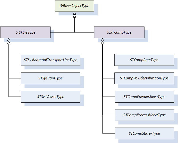
The OPC UA Companion Specification for Organic Coating - Material Supply Systems covers different parts of a material supply system. It builds on the OPC UA for Surface Technology - General Types, which defines the basic structure of machines and components in a surface treatment plant. The following figure shows which ObjectTypes have been defined in the present standard.
7 OPC UA ObjectTypes
7.1 STSysMaterialTransportLineType ObjectType Definition
The STSysMaterialTransportLineType provides relevant ObjectTypes and VariableTypes for controlling and monitoring a material transport line of a material supply system and is formally defined in Table 15.
| Attribute | Value | ||||
| BrowseName | STSysMaterialTransportLineType | ||||
| IsAbstract | False | ||||
| References | Node Class | BrowseName | DataType | TypeDefinition | Other |
|---|---|---|---|---|---|
| Subtype of the 5:STSysType defined in OPC 40700 | |||||
| 0:HasComponent | Object | 4:Monitoring | 4:MonitoringType | O | |
| 0:HasComponent | Object | 4:MachineryBuildingBlocks | 0:FolderType | M | |
| 0:HasComponent | Object | 5:Description | 0:FolderType | O | |
| Conformance Units | |||||
|---|---|---|---|---|---|
| MSS STSysMaterialTransportLineType Basic | |||||
| MSS STSysMaterialTransportLineType Monitoring | |||||
| MSS STSysMaterialTransportLineType Description |
Monitoring represents a collection of ObjectTypes and VariableTypes, representing the current state of the process that are assigned to the component.
MachineryBuildingBlocks represents a folder that directly references all those building blocks of the OPC UA for Machinery (OPC 40001-1, OPC 40001-3) which are implemented as an add-in.
Description represents a collection of ObjectTypes and VariableTypes that describe the material transport line. This may be information that is not an identifier for the system and that is static in character but must be stored on the server for some use cases. One example is the mesh size of a sieve, which does not vary but can be queried by cooperating systems.
The components of the STSysMaterialTransportLineType have additional references which are defined in Table 16.
| SourceBrowsePath | Reference Type | Is Forward | TargetBrowsePath | |||||
| 0:HasComponent | True |
|
The components of the STSysMaterialTransportLineType have additional subcomponents which are defined in Table 17.
| Source Path | Reference | NodeClass | BrowseName | DataType | TypeDefinition | Others | ||
| 0:HasComponent | Variable | RemainingDurationOfUse | 0:Double | 2:LifetimeVariableType | O | ||
| 0:HasComponent | Variable | FillState | 0:UInt16 | 0:MultiStateValueDiscreteType | O | ||
| 0:HasComponent | Object | AverageFlowVelocity | 6:ProcessValueType | O | |||
| 4:MachineryBuildingBlocks | 0:HasComponent | Object | LifetimeCounters | 4:MachineryLifetimeCounterType | O | |||
| 5:Description | 0:HasProperty | Variable | ContactMaterial | 0:String | 0:PropertyType | O | ||
| 5:Description | 0:HasComponent | Variable | FlowResistanceCoefficient | 0:Double | 0:AnalogUnitType | O | ||
| 5:Description | 0:HasComponent | Variable | PressureLossCoefficient | 0:Double | 0:AnalogUnitType | O | ||
| 5:Description | 0:HasComponent | Variable | CompressiveStrength | 0:Double | 0:AnalogUnitType | O | ||
| 5:Description | 0:HasComponent | Variable | Length | 0:Double | 0:AnalogUnitType | O | ||
| 5:Description | 0:HasComponent | Variable | CrossSection | 0:Double | 0:AnalogUnitType | O |
RemainingDurationOfUse represents the predicted remaining time that the material transport line will be in use/occupied in the current process.
FillState represents the occupancy of the material transport line. For the FillState an entry of Table 18 shall be used if appropriate. Since the Variable's TypeDefinition is a MultiStateValueDiscreteType, additional entries can be added if none of the suggested entries are suitable.
AverageFlowVelocity represents the calculated flow velocity of the material in the material transport line.
LifetimeCounters is used as defined in OPC 40001-1. In the information model for material supply systems, all counters shall be implemented according to the MachineryLifetimeCounterType of the OPC 40001-1 and shall be integrated with the HasComponent reference under this Object. This Object shall also be referenced as AddIn in the MachineryBuildingBlocks Folder.
ContactMaterial represents the type of material of the transport line which is in contact with the material transported in the material transport line.
FlowResistanceCoefficient represents the flow resistance between the ContactMaterial and the material transported in the material transport line.
PressureLossCoefficient represents the pressure loss coefficient in the material transport line.
CompressiveStrength represents the compressive strength/pressure resistance of the material transport line.
Length represents the transport length of the material transport line.
CrossSection represents the cross sectional flow area of the material transport line.
The component Variables of the STSysMaterialTransportLineType have additional Attributes defined in Table 18.
| BrowsePath | Value Attribute | Description Attribute | |||||
|
|
7.2 STSysRamType ObjectType Definition
The STSysRamType provides relevant ObjectTypes and VariableTypes for controlling and monitoring an overall ram system. It can contain several components as rams or vessels.
The STSysRamType is formally defined in Table 19.
| Attribute | Value | ||||
| BrowseName | STSysRamType | ||||
| IsAbstract | False | ||||
| References | Node Class | BrowseName | DataType | TypeDefinition | Other |
|---|---|---|---|---|---|
| Subtype of the 5:STSysType defined in OPC 40700 | |||||
| 0:HasAddIn | Object | 4:Components | 4:MachineComponentsType | O | |
| Conformance Units | |||||
|---|---|---|---|---|---|
| MSS STSysRamType Basic | |||||
| MSS STSysRamType Components |
Components represent a collection of ObjectTypes that are representing components of the ram.
The Components of the STSysRamType have additional subcomponents which are defined in Table 20.
| Source Path | Reference | NodeClass | BrowseName | DataType | TypeDefinition | Others |
| 4:Components | 0:HasComponent | Object | <Stirrer> | STCompStirrerType | OP | |
| 4:Components | 0:HasComponent | Object | <Heater> | STCompHeaterType | OP | |
| 4:Components | 0:HasComponent | Object | <Ram> | STCompRamType | MP | |
| 4:Components | 0:HasComponent | Object | <Vessel> | STSysVesselType | OP |
Stirrer describes a stirrer/agitator of a material supply system, its setpoints and the current readings.
Heater describes the material temperature control, the setpoints and the current readings of the heating component temperature.
Ram describes a single ram inside of the ram system, its setpoints and the current readings.
7.3 STCompRamType ObjectType Definition
The STCompRamType provides relevant ObjectTypes and VariableTypes for controlling and monitoring a ram unit. It is formally defined in Table 21.
| Attribute | Value | ||||
| BrowseName | STCompRamType | ||||
| IsAbstract | False | ||||
| References | Node Class | BrowseName | DataType | TypeDefinition | Other |
|---|---|---|---|---|---|
| Subtype of the 5:STCompType defined in OPC 40700 | |||||
| 0:HasComponent | Object | 4:Monitoring | 4:MonitoringType | O | |
| 0:HasComponent | Object | 4:MachineryBuildingBlocks | 0:FolderType | M | |
| 0:HasComponent | Object | 5:Description | 0:FolderType | O | |
| Conformance Units | |||||
|---|---|---|---|---|---|
| MSS STCompRamType Basic | |||||
| MSS STCompRamType Monitoring | |||||
| MSS STCompRamType Description |
Monitoring represents a collection of ObjectTypes and VariableTypes, representing the current state of the process that are assigned to the component.
MachineryBuildingBlocks represents a folder that directly references all those building blocks of the OPC UA for Machinery (OPC 40001-1, OPC 40001-3) which are implemented as an add-in.
Description represents a collection of ObjectTypes and VariableTypes that describe the ram. This may be information that is not an identifier for the system and that is static in character but must be stored on the server for some use cases. One example is the mesh size of a sieve, which does not vary but can be queried by cooperating systems.
The components of the STCompRamType have additional references which are defined in Table 22.
| SourceBrowsePath | Reference Type | Is Forward | TargetBrowsePath | |||||
| 0:HasComponent | True |
| |||||
| 0:HasComponent | True |
|
The components of the STCompRamType have additional subcomponents which are defined in Table 23.
| Source Path | Reference | NodeClass | BrowseName | DataType | TypeDefinition | Others | ||
| 0:HasComponent | Variable | DrumPresent | 0:Boolean | 0:TwoStateDiscreteType | O | ||
| 0:HasComponent | Variable | DiscreteFillingLevel | 0:UInt16 | 0:MultiStateValueDiscreteType | O | ||
| 0:HasComponent | Variable | CirculationActive | 0:Boolean | 0:TwoStateDiscreteType | O | ||
| 0:HasComponent | Variable | RamUnitReady | 0:Boolean | 0:TwoStateDiscreteType | O | ||
| 0:HasComponent | Variable | RemainingCycles | 0:UInt16 | 2:LifetimeVariableType | O | ||
| 0:HasComponent | Variable | RemainingMaterialTime | 0:Double | 2:LifetimeVariableType | O | ||
| 0:HasComponent | Object | MeasuredFillingLevel | 6:ProcessValueType | O | |||
| 0:HasComponent | Object | DownwardPressureRam | 6:ProcessValueType | O | |||
| 0:HasComponent | Object | InputCurrentRam | 6:ProcessValueType | O | |||
| 0:HasComponent | Object | InputPressureRam | 6:ProcessValueType | O | |||
| 0:HasComponent | Object | MaterialTemperature | 6:ProcessValueType | O | |||
| 4:MachineryBuildingBlocks | 0:HasAddIn | Object | LifetimeCounters | 4:MachineryLifetimeCounterType | O | |||
| 5:Description | Variable | TypeOfRam | 0:UInt16 | 0:MultiStateValueDiscreteType | O | |||
| 5:Description | Variable | DrumVolumeClass | 0:UInt16 | 0:MultiStateValueDiscreteType | O | |||
| 5:Description | Variable | DrumInnerDiameter | 0:Double | 0:AnalogUnitType | O |
DrumPresent indicates if a drum is present on the ram unit. True is representing the state "present" while False represents "not present".
DiscreteFillingLevel gives a rough indication of the filling level of the drum on the ram unit intended for human operators and process control systems. Possible entries can be found in Table 24.
CirculationActive indicates whether the material is being circulated in the ram unit. True is representing the state "active" while False represents "not active".
RamUnitReady indicates that the unit is ready for operation. True is representing the state "ready" while False represents "not ready".
RemainingCycles indicates the remaining process cycles that can be operated from the currently mounted barrel in the ram.
RemainingMaterialTime indicates the remaining time that can be operated from the currently mounted barrel in the ram.
MeasuredFillingLevel gives an indication of the numeric filling level of the drum on the ram unit intended for process control systems.
DownwardPressureRam is the pressure exerted by the ram onto the material in the barrel. It is the calculated value which can be made available for pneumatic, electric and hydraulically driven rams.
InputCurrentRam is the amount of current delivered to an electrically driven ram.
InputPressureRam is the pressure supplied to a pneumatic or hydraulic piston of the ram where the area ratio of the drive piston to the drum diameter will result in a proportional pressure compared to the DownwardPressureRam.
MaterialTemperature is the temperature of the material inside of the barrel. The temperature should ideally be measured at the intake point of the follow plate.
LifetimeCounters represents a folder that directly references all those Variables of the type definition LifetimeVariableTypes integrated in the STCompRamType.
TypeOfRam describes the type of the ram. Possible entries can be found in Table 24.
DrumVolumeClass describes the barrel class the ram and its follow plate are intended for. Possible entries can be found in Table 24.
DrumInnerDiameter describes the inner diameter of the drum the ram unit was originally specified for.
The component Variables of the STCompRamType have additional Attributes defined Table 24.
| BrowsePath | Value Attribute | Description Attribute | ||||
| [ {"Value": 0, "DisplayName": "empty", "Description": ""}, {"Value": 1, "DisplayName": "almost empty", "Description": ""}, {"Value": 2, "DisplayName": "full", "Description": ""}, ] | |||||
| [ {"Value": 0, "DisplayName": "SinglePostRam", "Description": ""}, {"Value": 1, "DisplayName": "DualPostRam", "Description": ""}, ] | |||||
| [ {"Value": 0, "DisplayName": "20 liters", "Description": ""}, {"Value": 1, "DisplayName": "200 liters", "Description": ""}, {"Value": 2, "DisplayName": "208 liters", "Description": ""}, {"Value": 3, "DisplayName": "210 liters", "Description": ""}, {"Value": 4, "DisplayName": "216.5 liters", "Description": ""}, ] |
7.4 STCompPowderVibrationType ObjectType Definition
The STCompPowderVibrationType provides relevant ObjectTypes and VariableTypes for controlling and monitoring a powder vibration unit of a material supply system and is formally defined in Table 25.
| Attribute | Value | ||||
| BrowseName | STCompPowderVibrationType | ||||
| IsAbstract | False | ||||
| References | Node Class | BrowseName | DataType | TypeDefinition | Other |
|---|---|---|---|---|---|
| Subtype of the 5:STCompType defined in OPC 40700 | |||||
| 0:HasComponent | Object | 4:Monitoring | 4:MonitoringType | O | |
| Conformance Units | |||||
|---|---|---|---|---|---|
| MSS STCompPowderVibrationType Basic | |||||
| MSS STCompPowderVibrationType Monitoring |
Monitoring represents a collection of ObjectTypes and VariableTypes, representing the current state of the process that are assigned to the component.
The components of the STCompPowderVibrationType have additional subcomponents which are defined in Table 26.
| Source Path | Reference | NodeClass | BrowseName | DataType | TypeDefinition | Others | ||
| 0:HasComponent | Variable | VesselVibration | 0:Boolean | 0:TwoStateDiscreteType | O |
VesselVibration represents the state (on/off) of the powder vibration unit. True is representing the state "VibrationOn" while False represents "VibrationOff".
7.5 STCompPowderSieveType ObjectType Definition
The STCompPowderSieveType provides relevant ObjectTypes and VariableTypes for controlling and monitoring a powder sieve of a material supply system and is formally defined in Table 27.
| Attribute | Value | ||||
| BrowseName | STCompPowderSieveType | ||||
| IsAbstract | False | ||||
| References | Node Class | BrowseName | DataType | TypeDefinition | Other |
|---|---|---|---|---|---|
| Subtype of the 5:STCompType defined in OPC 40700 | |||||
| 0:HasComponent | Object | 5:Description | 0:FolderType | O | |
| Conformance Units | |||||
|---|---|---|---|---|---|
| MSS STCompPowderSieveType Basic | |||||
| MSS STCompPowderSieveType Description |
Description represents a collection of ObjectTypes and VariableTypes that describe the powder sieve. This may be information that is not an identifier for the system or that is static in character but must be stored on the server for some use cases. One example is the mesh size of a sieve, which does not vary but can be queried by cooperating systems.
The components of the STCompPowderSieveType have additional subcomponents which are defined in Table 28.
| Source Path | Reference | NodeClass | BrowseName | DataType | TypeDefinition | Others |
| 5:Description | 0:HasComponent | Variable | PowderSieveMeshSize | 0:Double | 0:AnalogUnitType | O |
PowderSieveMeshSize represents the mesh size of the powder sieve.
7.6 STCompProcessValveType ObjectType Definition
The STCompProcessValveType provides relevant variables and parameters for controlling and monitoring a valve of a material supply system and is formally defined in Table 29.
| Attribute | Value | ||||
| BrowseName | STCompProcessValveType | ||||
| IsAbstract | False | ||||
| References | Node Class | BrowseName | DataType | TypeDefinition | Other |
|---|---|---|---|---|---|
| Subtype of the 5:STCompType defined in OPC 40700 | |||||
| 0:HasComponent | Object | 4:Monitoring | 4:MonitoringType | O | |
| 0:HasComponent | Object | 4:MachineryBuildingBlocks | 0:FolderType | M | |
| 0:HasComponent | Object | 5:Description | 0:FolderType | O | |
| Conformance Units | |||||
|---|---|---|---|---|---|
| MSS STCompProcessValveType Basic | |||||
| MSS STCompProcessValveType Monitoring | |||||
| MSS STCompProcessValveType Description |
Monitoring represents a collection of ObjectTypes and VariableTypes, representing the current state of the process that are assigned to the component.
MachineryBuildingBlocks represents a folder that directly references all those building blocks of the OPC UA for Machinery (OPC 40001-1, OPC 40001-3) which are implemented as an add-in.
Description represents a collection of ObjectTypes and VariableTypes that describe the valve. This may be information that is not an identifier for the system and that is static in character but must be stored on the server for some use cases. One example is the mesh size of a sieve, which does not vary but can be queried by cooperating systems.
The components of the STCompProcessValveType have additional references which are defined in Table 30.
| SourceBrowsePath | Reference Type | Is Forward | TargetBrowsePath | |||||
| 0:HasProperty | True |
| |||||
| 0:HasComponent | True |
|
The components of the STCompProcessValveType have additional subcomponents which are defined in Table 31.
| Source Path | Reference | NodeClass | BrowseName | DataType | TypeDefinition | Others | ||
| 0:HasComponent | Object | OpeningDegree | 6:ProcessValueType | O | |||
| 0:HasProperty | Variable | 2:OperationCycleCounter | 0:UInteger | 0:PropertyType | O | ||
| 0:HasProperty | Variable | OpenTime | 0:Duration | 0:PropertyType | O | ||
| 0:HasProperty | Variable | CloseTime | 0:Duration | 0:PropertyType | O | ||
| 0:HasComponent | Object | DutyCycle | 6:ProcessValueType | O | |||
| 0:HasComponent | Object | SwitchingFrequency | 6:ProcessValueType | O | |||
| 0:HasComponent | Variable | RemainingCycles | 0:Number | 2:LifetimeVariableType | O | ||
| 4:MachineryBuildingBlocks | 0:HasAddIn | Object | LifetimeCounters | 4:MachineryLifetimeCounterType | O | |||
| 4:MachineryBuildingBlocks | 0:HasAddIn | Object | OperationCounters | 4:MachineryOperationCounterType | O | |||
| 5:Description | 0:HasComponent | Variable | FlowCrossSection | 0:Double | 0:AnalogUnitType | O | ||
| 5:Description | 0:HasComponent | Variable | Travel | 0:Double | 0:AnalogUnitType | O | ||
| 5:Description | 0:HasProperty | Variable | LifetimeCycles | 0:UInt16 | 0:PropertyType | O | ||
| 5:Description | 0:HasProperty | Variable | MinimumPulseOpenTime | 0:Duration | 0:PropertyType | O | ||
| 5:Description | 0:HasProperty | Variable | MinimumPulseCloseTime | 0:Duration | 0:PropertyType | O | ||
| 5:Description | 0:HasProperty | Variable | OpeningTime | 0:Duration | 0:PropertyType | O | ||
| 5:Description | 0:HasProperty | Variable | ClosingTime | 0:Duration | 0:PropertyType | O | ||
| 5:Description | 0:HasComponent | Variable | MaterialPressureMax | 0:Double | 0:AnalogUnitType | O | ||
| 5:Description | 0:HasComponent | Variable | FlowVolumeMax | 0:Double | 0:AnalogUnitType | O | ||
| 5:Description | 0:HasComponent | Variable | TypeOfActuationEnergy | 0:UInt16 | 0:MultiStateValueDiscreteType | O |
OpeningDegree represents the opening degree of the valve.
OperationCycleCounter represents the number of switching cycles of the valve since reset.
OpenTime represents the duration of "Open" status since last opening of the valve.
CloseTime represents the duration of "Close" status since last closing of the valve.
DutyCycle represents the value of the duty cycle of the valve.
SwitchingFrequency represents the frequency value of the valve.
RemainingCycles represents the current remaining cycles the valve can operate before reaching the expected LifetimeCycles.
LifetimeCounters represents a folder that directly references all those Variables of the type definition LifetimeVariableTypes integrated in the STCompProcessValveType.
FlowCrossSection represents the smallest flow cross-section of the valve.
Travel represents the translatory path of the switching element of the valve. As the engineering unit can be chosen by the user, linear valves and ball valves can be mapped by this Variable.
LifetimeCycles represents the expected lifetime of the valve in number of switching cycles.
MinimumPulseOpenTime represents the shortest possible duration of the "Open" state of the valve.
MinimumPulseCloseTime represents the shortest possible duration of the "Close" state of the valve.
OpeningTime represents the duration of the state change from "Closed" to "Open" for the valve.
ClosingTime represents the duration of the state change from "Open" to "Closed" for the valve.
MaterialPressureMax represents the maximum permissible material pressure of the valve.
FlowVolumeMax represents the maximum possible flow volume with water of the valve.
TypeOfActuationEnergy represents the type of energy used for controlling the valve (e.g. pneumatic, electric).
The component Variables of the STCompProcessValveType have additional Attributes defined in Table 32.
| BrowsePath | Value Attribute | Description Attribute | |||
| [ {"Value": 0, "DisplayName": "pneumatic", "Description": ""}, {"Value": 1, "DisplayName": "electric", "Description": ""}, {"Value": 2, "DisplayName": "hydraulic", "Description": ""}, ] |
7.7 STSysVesselType ObjectType Definition
The STSysVesselType provides relevant variables and parameters for controlling and monitoring a vessel of a material supply system. As the Components Object of the STSysVesselType is optional, a simple vessel without any additional components can also be represented by this ObjectType.
The STSysVesselType is formally defined in Table 33.
| Attribute | Value | ||||
| BrowseName | STSysVesselType | ||||
| IsAbstract | False | ||||
| References | Node Class | BrowseName | DataType | TypeDefinition | Other |
|---|---|---|---|---|---|
| Subtype of the 5:STSysType defined in OPC 40700 | |||||
| 0:HasComponent | Object | 4:Monitoring | 4:MonitoringType | O | |
| 0:HasAddIn | Object | 4:Components | 4:MachineComponentsType | O | |
| 0:HasComponent | Object | 5:Description | 0:FolderType | O | |
| Conformance Units | |||||
|---|---|---|---|---|---|
| MSS STSysVesselType Basic | |||||
| MSS STSysVesselType Monitoring | |||||
| MSS STSysVesselType Components | |||||
| MSS STSysVesselType Description |
Monitoring represents a collection of ObjectTypes and VariableTypes, representing the current state of the process that are assigned to the component.
Components represents a collection of ObjectTypes that are representing components of the vessel.
Description represents a collection of ObjectTypes and VariableTypes that describe the vessel. This may be information that is not an identifier for the system and that is static in character but must be stored on the server for some use cases. One example is the mesh size of a sieve, which does not vary but can be queried by cooperating systems.
The components of the STSysVesselType have additional subcomponents which are defined in Table 34.
| Source Path | Reference | NodeClass | BrowseName | DataType | TypeDefinition | Others | ||
| 4:Components | 0:HasComponent | Object | <Stirrer> | STCompStirrerType | OP | |||
| 4:Components | 0:HasComponent | Object | <Heater> | STCompHeaterType | OP | |||
| 4:Components | 0:HasComponent | Object | <Valve> | STCompProcessValveType | OP | |||
| 0:HasComponent | Object | FillVolume | 6:ProcessValueType | O | |||
| 0:HasComponent | Object | RelativePressure | 6:ProcessValueType | O | |||
| 0:HasComponent | Object | Temperature | 6:ProcessValueType | O | |||
| 5:Description | 0:HasComponent | Variable | VesselVolume | 0:Double | 0:AnalogUnitType | O |
Stirrer describes a stirrer/agitator of a material supply system, its setpoints and the current readings.
Heater describes the material temperature control, the setpoints and the current readings.
Valve describes a valve, its setpoints and the current readings.
FillVolume represents the quantity, either by volume or by weight, of coating material in the vessel.
RelativePressure represents the measured pressure of the vessel as difference compared to atmospheric pressure. It can also include the upper and lower design pressure of the vessel.
Temperature represents the measured temperature of the material in the vessel. Ideally the measurement point is close to the point of outflow. It can also include the upper and lower design temperature of the vessel.
VesselVolume represents the usable volume of the vessel.
7.8 STCompStirrerType ObjectType Definition
The STCompStirrerType provides relevant variables and parameters for controlling and monitoring a stirrer/agitator of a material supply system and is formally defined in Table 35.
| Attribute | Value | ||||
| BrowseName | STCompStirrerType | ||||
| IsAbstract | False | ||||
| References | Node Class | BrowseName | DataType | TypeDefinition | Other |
|---|---|---|---|---|---|
| Subtype of the 5:STCompType defined in OPC 40700 | |||||
| 0:HasComponent | Object | 4:Monitoring | 4:MonitoringType | O | |
| Conformance Units | |||||
|---|---|---|---|---|---|
| MSS STCompStirrerType Basic | |||||
| MSS STCompStirrerType Monitoring |
Monitoring represents a collection of ObjectTypes and VariableTypes, representing the current state of the process that are assigned to the component.
The components of the STCompStirrerType have additional subcomponents which are defined in Table 36.
| Source Path | Reference | NodeClass | BrowseName | DataType | TypeDefinition | Others | ||
| 0:HasComponent | Object | StirrerSpeed | 6:ProcessValueType | O | |||
| 0:HasComponent | Object | StirrerTorque | 6:ProcessValueType | O |
StirrerSpeed represents the rotational speed (e.g. rpm) of the stirrer/agitator. Values greater than 0 represent clockwise rotation.
StirrerTorque represents the current torque of the stirrer.
7.9 STCompHeaterType ObjectType Definition
The STCompHeaterType provides relevant variables and parameters for controlling and monitoring the heater of vessel and inline heating modules.
The STCompHeaterType is formally defined in Table 37.
| Attribute | Value | ||||
| BrowseName | STCompHeaterType | ||||
| IsAbstract | False | ||||
| References | Node Class | BrowseName | DataType | TypeDefinition | Other |
|---|---|---|---|---|---|
| Subtype of the 5:STCompType defined in OPC 40700 | |||||
| 0:HasComponent | Object | 4:Monitoring | 4:MonitoringType | O | |
| 0:HasComponent | Object | 5:Description | 0:FolderType | O | |
| Conformance Units | |||||
|---|---|---|---|---|---|
| MSS STCompHeaterType Basic | |||||
| MSS STCompHeaterType Monitoring | |||||
| MSS STCompHeaterType Description |
Monitoring represents a collection of ObjectTypes and VariableTypes, representing the current state of the process that are assigned to the component.
Description represents a collection of ObjectTypes and VariableTypes that describe the heater. This may be information that is not an identifier for the system and that is static in character but must be stored on the server for some use cases. One example is the mesh size of a sieve, which does not vary but can be queried by cooperating systems.
The components of the STCompHeaterType have additional subcomponents which are defined in Table 38.
| Source Path | Reference | NodeClass | BrowseName | DataType | TypeDefinition | Others | ||
| 0:HasComponent | Variable | TypeOfHeating | 0:UInt16 | 0:MultiStateValueDiscreteType | O | ||
| 0:HasComponent | Object | Temperature | 6:ProcessValueType | M | |||
| 0:HasComponent | Object | StandbyTemperature | 6:ProcessValueType | O | |||
| 0:HasComponent | Object | HeatingPower | 6:ProcessValueType | O | |||
| 0:HasProperty | Variable | HeatingPowerRelative | 0:Number | 0:PropertyType | O | ||
| 0:HasComponent | Object | HeatUpTime | 6:ProcessValueType | O | |||
| 0:HasComponent | Object | HeatThroughTime | 6:ProcessValueType | O | |||
| 0:HasComponent | Object | StandbyTimeout | 6:ProcessValueType | O | |||
| 5:Description | 0:HasComponent | Variable | TypeOfDevice | 0:UInt16 | 0:MultiStateValueDiscreteType | M |
TypeOfHeating is describing how the material is heated.
Temperature represents the temperature currently measured and or set.
StandbyTemperature represents the temperature maintained in a standby mode of the heating system.
HeatingPower represents the heating output of the heating system.
HeatingPowerRelative represents the percentage of the maximum heating power currently supplied.
HeatUpTime represents the time that the heating part needs to heat up to the set temperature.
HeatThroughTime represents the time that the heating part needs to heat through completely. The HeatThroughTime starts when first reaching the temperature set in Temperature.
StandbyTimeout represents the time after which the temperature control unit switches to standby mode due to the inactivity of the system.
TypeOfDevice represents the physical design of the heater used.
The component Variables of the STCompHeaterType have additional Attributes defined in Table 39.
| BrowsePath | Value Attribute | Description Attribute | ||||
| [ {"Value": 0, "DisplayName": "indirect fluid", "Description": ""}, {"Value": 1, "DisplayName": "electrical", "Description": ""}, ] | |||||
| [ {"Value": 0, "DisplayName": "drum floor heater", "Description": ""}, {"Value": 1, "DisplayName": "heating band", "Description": ""}, {"Value": 2, "DisplayName": "heated follow plate", "Description": ""}, ] |
8 Profiles and Conformance Units
8.1 Conformance Units
This chapter defines the corresponding Conformance Units for the OPC UA Information Model for ST - OCT - Material Supply Systems.
| Category | Title | Description |
| Server | MSS STSysMaterialTransportLineType Basic | There is at least one instance of STSysMaterialTransportLineType on the Server. The instance has all mandatory Nodes. |
| Server | MSS STSysMaterialTransportLineType Monitoring | There is at least one instance of STSysMaterialTransportLineType on the Server. The instance has all mandatory Nodes and the optional Node Monitoring including at least one of the optional Nodes underneath. |
| Server | MSS STSysMaterialTransportLineType Description | There is at least one instance of STSysMaterialTransportLineType on the Server. The instance has all mandatory Nodes and the optional Node Description including at least one of the optional Nodes underneath. |
| Server | MSS STSysRamType Basic | There is at least one instance of STSysRamType on the Server. The instance has all mandatory Nodes. |
| Server | MSS STSysRamType Components | There is at least one instance of STSysRamType on the Server. The instance has all mandatory Nodes and the optional Node Components including at least one of the optional Nodes underneath. |
| Server | MSS STCompRamType Basic | There is at least one instance of STCompRamType on the Server. The instance has all mandatory Nodes. |
| Server | MSS STCompRamType Monitoring | There is at least one instance of STCompRamType on the Server. The instance has all mandatory Nodes and the optional Node Monitoring including at least one of the optional Nodes underneath. |
| Server | MSS STCompRamType Description | There is at least one instance of STCompRamType on the Server. The instance has all mandatory Nodes and the optional Node Description including at least one of the optional Nodes underneath. |
| Server | MSS STCompPowderVibrationType Basic | There is at least one instance of STCompPowderVibrationType on the Server. The instance has all mandatory Nodes. |
| Server | MSS STCompPowderVibrationType Monitoring | There is at least one instance of STCompPowderVibrationType on the Server. The instance has all mandatory Nodes and the optional Node Monitoring including at least one of the optional Nodes underneath. |
| Server | MSS STCompPowderSieveType Basic | There is at least one instance of STCompPowderSieveType on the Server. The instance has all mandatory Nodes. |
| Server | MSS STCompPowderSieveType Description | There is at least one instance of STCompPowderSieveType on the Server. The instance has all mandatory Nodes and the optional Node Description including at least one of the optional Nodes underneath. |
| Server | MSS STCompProcessValveType Basic | There is at least one instance of STCompProcessValveType on the Server. The instance has all mandatory Nodes. |
| Server | MSS STCompProcessValveType Monitoring | There is at least one instance of STCompProcessValveType on the Server. The instance has all mandatory Nodes and the optional Node Monitoring including at least one of the optional Nodes underneath. |
| Server | MSS STCompProcessValveType Description | There is at least one instance of STCompProcessValveType on the Server. The instance has all mandatory Nodes and the optional Node Description including at least one of the optional Nodes underneath. |
| Server | MSS STSysVesselType Basic | There is at least one instance of STSysVesselType on the Server. The instance has all mandatory Nodes. |
| Server | MSS STSysVesselType Monitoring | There is at least one instance of STSysVesselType on the Server. The instance has all mandatory Nodes and the optional Node Monitoring including at least one of the optional Nodes underneath. |
| Server | MSS STSysVesselType Components | There is at least one instance of STSysVesselType on the Server. The instance has all mandatory Nodes and the optional Node Components including at least one of the optional Nodes underneath. |
| Server | MSS STSysVesselType Description | There is at least one instance of STSysVesselType on the Server. The instance has all mandatory Nodes and the optional Node Description including at least one of the optional Nodes underneath. |
| Server | MSS STCompStirrerType Basic | There is at least one instance of STCompStirrerType on the Server. The instance has all mandatory Nodes. |
| Server | MSS STCompStirrerType Monitoring | There is at least one instance of STCompStirrerType on the Server. The instance has all mandatory Nodes and the optional Node Monitoring including at least one of the optional Nodes underneath. |
| Server | MSS STCompHeaterType Basic | There is at least one instance of STCompHeaterType on the Server. The instance has all mandatory Nodes. |
| Server | MSS STCompHeaterType Monitoring | There is at least one instance of STCompHeaterType on the Server. The instance has all mandatory Nodes and the optional Node Monitoring including at least one of the optional Nodes underneath. |
| Server | MSS STCompHeaterType Description | There is at least one instance of STCompHeaterType on the Server. The instance has all mandatory Nodes and the optional Node Description including at least one of the optional Nodes underneath. |
8.2 Profiles
8.2.1 Profile list
Table 41 lists all Profiles defined in this document and defines their URIs.
8.2.2 Server Facets
8.2.2.1 Overview
The following sections specify the Facets available for Servers that implement the Organic Coating Technology - Material Supply Systems companion specification. Each section defines and describes a Facet or Profile.
8.2.2.2 MSS Basic Server Facet
This Facet defines support for base ST - OCT - Material Supply Systems functionality. At least three of the optional Conformance Units must be implemented.
| Group | Conformance Unit / Profile Title | Mandatory / Optional |
| SurfaceTechnology/OCT-MSS | MSS STSysMaterialTransportLineType Basic | M |
| SurfaceTechnology/OCT-MSS | MSS STSysRamType Basic | O |
| SurfaceTechnology/OCT-MSS | MSS STCompRamType Basic | O |
| SurfaceTechnology/OCT-MSS | MSS STCompPowderVibrationType Basic | O |
| SurfaceTechnology/OCT-MSS | MSS STCompPowderSieveType Basic | O |
| SurfaceTechnology/OCT-MSS | MSS STCompProcessValveType Basic | O |
| SurfaceTechnology/OCT-MSS | MSS STSysVesselType Basic | O |
| SurfaceTechnology/OCT-MSS | MSS STCompStirrerType Basic | O |
8.2.2.3 MSS Advanced Server Facet
This Facet defines support for advanced ST - OCT - Material Supply Systems functionality. At least six of the optional Conformance Units must be implemented.
| Group | Conformance Unit / Profile Title | Mandatory / Optional |
| SurfaceTechnology/OCT-MSS | MSS STSysMaterialTransportLineType Basic | M |
| SurfaceTechnology/OCT-MSS | MSS STSysRamType Basic | O |
| SurfaceTechnology/OCT-MSS | MSS STCompRamType Basic | O |
| SurfaceTechnology/OCT-MSS | MSS STCompPowderVibrationType Basic | O |
| SurfaceTechnology/OCT-MSS | MSS STCompPowderSieveType Basic | O |
| SurfaceTechnology/OCT-MSS | MSS STCompProcessValveType Basic | O |
| SurfaceTechnology/OCT-MSS | MSS STSysVesselType Basic | O |
| SurfaceTechnology/OCT-MSS | MSS STCompStirrerType Basic | O |
8.2.2.4 MSS Advanced Monitoring Server Facet
This Facet defines support for advanced ST - OCT - Material Supply Systems functionality. At least four of the optional Conformance Units must be implemented.
| Group | Conformance Unit / Profile Title | Mandatory / Optional |
| SurfaceTechnology/OCT-MSS | MSS STSysMaterialTransportLineType Monitoring | M |
| SurfaceTechnology/OCT-MSS | MSS STCompRamType Monitoring | O |
| SurfaceTechnology/OCT-MSS | MSS STCompPowderVibrationType Monitoring | O |
| SurfaceTechnology/OCT-MSS | MSS STCompProcessValveType Monitoring | O |
| SurfaceTechnology/OCT-MSS | MSS STSysVesselType Monitoring | O |
| SurfaceTechnology/OCT-MSS | MSS STCompStirrerType Monitoring | O |
8.2.2.5 MSS Advanced STSysMaterialTransportLine Facet
This Facet defines support for advanced functionality of the implemented StSysMaterialTransportLineType instances. All listed Conformance Units must be implemented.
| Group | Conformance Unit / Profile Title | Mandatory / Optional |
| SurfaceTechnology/OCT-MSS | MSS STSysMaterialTransportLineType Basic | M |
| SurfaceTechnology/OCT-MSS | MSS STSysMaterialTransportLineType Monitoring | M |
| SurfaceTechnology/OCT-MSS | MSS STSysMaterialTransportLineType Description | M |
8.2.2.6 MSS Advanced STSysRam Facet
This Facet defines support for advanced functionality of the implemented STSysRamType instances. All listed Conformance Units must be implemented.
| Group | Conformance Unit / Profile Title | Mandatory / Optional |
| SurfaceTechnology/OCT-MSS | MSS STSysRamType Basic | M |
| SurfaceTechnology/OCT-MSS | MSS STSysRamType Components | M |
8.2.2.7 MSS Advanced STCompRam Facet
This Facet defines support for advanced functionality of the implemented STCompRamType instances. All listed Conformance Units must be implemented.
| Group | Conformance Unit / Profile Title | Mandatory / Optional |
| SurfaceTechnology/OCT-MSS | MSS STCompRamType Basic | M |
| SurfaceTechnology/OCT-MSS | MSS STCompRamType Monitoring | M |
| SurfaceTechnology/OCT-MSS | MSS STCompRamType Description | M |
8.2.2.8 MSS Advanced STCompPowderSieve Facet
This Facet defines support for advanced functionality of the implemented STCompPowderSieveType instances. All listed Conformance Units must be implemented.
| Group | Conformance Unit / Profile Title | Mandatory / Optional |
| SurfaceTechnology/OCT-MSS | MSS STCompPowderSieveType Basic | M |
| SurfaceTechnology/OCT-MSS | MSS STCompPowderSieveType Description | M |
8.2.2.9 MSS Advanced STCompProcessValve Facet
This Facet defines support for advanced functionality of the implemented STCompProcessValveType instances. All listed Conformance Units must be implemented.
| Group | Conformance Unit / Profile Title | Mandatory / Optional |
| SurfaceTechnology/OCT-MSS | MSS STCompProcessValveType Basic | M |
| SurfaceTechnology/OCT-MSS | MSS STCompProcessValveType Monitoring | M |
| SurfaceTechnology/OCT-MSS | MSS STCompProcessValveType Description | M |
8.2.2.10 MSS Advanced STSysVessel Facet
This Facet defines support for advanced functionality of the implemented STSysVesselType instances. All listed Conformance Units must be implemented.
| Group | Conformance Unit / Profile Title | Mandatory / Optional |
| SurfaceTechnology/OCT-MSS | MSS STSysVesselType Basic | M |
| SurfaceTechnology/OCT-MSS | MSS STSysVesselType Monitoring | M |
| SurfaceTechnology/OCT-MSS | MSS STSysVesselType Components | M |
| SurfaceTechnology/OCT-MSS | MSS STSysVesselType Description | M |
8.2.3 Client Facets
This specification does not define any Client Facets.
9 Namespaces
9.1 Namespace Metadata
Table 51 defines the namespace metadata for this document. The Object is used to provide version information for the namespace and an indication about static Nodes. Static Nodes are identical for all Attributes in all Servers, including the Value Attribute. See OPC 10000-5 for more details.
The information is provided as Object of type NamespaceMetadataType. This Object is a component of the Namespaces Object that is part of the Server Object. The NamespaceMetadataType ObjectType and its Properties are defined in OPC 10000-5.
The version information is also provided as part of the ModelTableEntry in the UANodeSet XML file. The UANodeSet XML schema is defined in OPC 10000-6.
| Attribute | Value | ||
| BrowseName | http://opcfoundation.org/UA/SurfaceTechnology/OCT-MSS/ | ||
| Property | DataType | Value | |
|---|---|---|---|
| NamespaceUri | String | http://opcfoundation.org/UA/SurfaceTechnology/OCT-MSS/ | |
| NamespaceVersion | String | 1.0.0 | |
| NamespacePublicationDate | DateTime | 2026-08-01 | |
| IsNamespaceSubset | Boolean | False | |
| StaticNodeIdTypes | IdType [] | 0 | |
| StaticNumericNodeIdRange | NumericRange [] | ||
| StaticStringNodeIdPattern | String | ||
9.2 Handling of OPC UA Namespaces
Namespaces are used by OPC UA to create unique identifiers across different naming authorities. The Attributes NodeId and BrowseName are identifiers. A Node in the UA AddressSpace is unambiguously identified using a NodeId. Unlike NodeIds, the BrowseName cannot be used to unambiguously identify a Node. Different Nodes may have the same BrowseName. They are used to build a browse path between two Nodes or to define a standard Property.
Servers may often choose to use the same namespace for the NodeId and the BrowseName. However, if they want to provide a standard Property, its BrowseName shall have the namespace of the standards body although the namespace of the NodeId reflects something else, for example the EngineeringUnits Property. All NodeIds of Nodes not defined in this document shall not use the standard namespaces.
Table 52 provides a list of mandatory and optional namespaces used in an OPC UA for Organic Coating Technology - Material Supply System OPC UA Server.
| NamespaceURI | Description |
| http://opcfoundation.org/UA/ | Namespace for NodeIds and BrowseNames defined in the OPC UA specification. This namespace shall have namespace index 0. |
| Local Server URI | Namespace for nodes defined in the local server. This namespace shall have namespace index 1. |
| http://opcfoundation.org/UA/DI/ | Namespace for NodeIds and BrowseNames defined in OPC 10000-100. The namespace index is Server specific. |
| http://opcfoundation.org/UA/IA/ | Namespace for NodeIds and BrowseNames defined in OPC 10000-200. The namespace index is Server specific. |
| http://opcfoundation.org/UA/Machinery/ | Namespace for NodeIds and BrowseNames defined in OPC 40001-1. The namespace index is Server specific. |
| http://opcfoundation.org/UA/ISA95-JOBCONTROL_V2/ | Namespace for NodeIds and BrowseNames defined in OPC 10031-4. The namespace index is Server specific. |
| Namespace for NodeIds and BrowseNames defined in OPC 40001-3. The namespace index is Server specific. | |
| http://opcfoundation.org/UA/SurfaceTechnology/GeneralTypes/ | Namespace for NodeIds and BrowseNames defined in OPC 40700. The namespace index is Server specific. |
| http://opcfoundation.org/UA/Dictionary/IRDI | Namespace for NodeIds of IRDI objects using HasDictionaryEntry. The namespace index is server specific. |
| http://opcfoundation.org/UA/PADIM/ | Namespace for NodeIds and BrowseNames defined in OPC UA for Process Automation Devices 30081. The namespace index is Server specific. |
| http://opcfoundation.org/UA/Machinery/ProcessValues/ | Namespace for NodeIds and BrowseNames defined in OPC UA for Machinery 40001-2. The namespace index is Server specific. |
| http://opcfoundation.org/UA/SurfaceTechnology/OCT-MSS/ | Namespace for NodeIds and BrowseNames defined in this document. The namespace index is Server specific. |
| Vendor specific types | A Server may provide vendor-specific types like types derived from ObjectTypes defined in this document in a vendor-specific namespace. |
| Vendor specific instances | A Server provides vendor-specific instances of the standard types or vendor-specific instances of vendor-specific types in a vendor-specific namespace. It is recommended to separate vendor specific types and vendor specific instances into two or more namespaces. |
Table 53 provides a list of namespaces and their indices used for BrowseNames in this document. The default namespace of this document is not listed since all BrowseNames without prefix use this default namespace.
| NamespaceURI | Namespace Index | Example |
| http://opcfoundation.org/UA/ | 0 | 0:EngineeringUnits |
| http://opcfoundation.org/UA/DI/ | 2 | 2:DeviceRevision |
| http://opcfoundation.org/UA/IA/ | 3 | 3:BasicStacklightType |
| http://opcfoundation.org/UA/Machinery/ | 4 | 4:MachineIdentificationType |
| http://opcfoundation.org/UA/SurfaceTechnology/GeneralTypes/ | 5 | 5:STSysType |
| http://opcfoundation.org/UA/Machinery/ProcessValues/ | 6 | 6:ProcessValueType |
Annex A OPC UA for ST - OCT - Material Supply Systems Namespace and mappings (Normative)
A.1 NodeSet and supplementary files for OPC UA for ST - OCT - Material Supply Systems Information Model
The OPC UA for ST - OCT - Material Supply Systems Information Model is identified by the following URI:
http://opcfoundation.org/UA/SurfaceTechnology/OCT-MSS/
Documentation for the NamespaceUri can be found here.
The NodeSet associated with this version of specification can be found here:
The NodeSet associated with the latest version of the specification can be found here:
Supplementary files for the OPC UA for ST - OCT - Material Supply Systems Information Model can be found here:
The files associated with the latest version of the specification can be found here:
A.2 Capability Identifier
The capability identifier for this document shall be:
SurfaceTechnology/OCT-MSS___________
Agreement of Use
COPYRIGHT RESTRICTIONS
This document is provided "as is" by the OPC Foundation and VDMA.
Right of use for this specification is restricted to this specification and does not grant rights of use for referred documents.
Right of use for this specification will be granted without cost.
This document may be distributed through computer systems, printed or copied as long as the content remains unchanged and the document is not modified.
OPC Foundation and VDMA do not guarantee usability for any purpose and shall not be made liable for any case using the content of this document.
The user of the document agrees to indemnify OPC Foundation and VDMA and their officers, directors and agents harmless from all demands, claims, actions, losses, damages (including damages from personal injuries), costs and expenses (including attorneys' fees) which are in any way related to activities associated with its use of content from this specification.
The document shall not be used in conjunction with company advertising, shall not be sold or licensed to any party.
The intellectual property and copyright is solely owned by the OPC Foundation and VDMA.
PATENTS
The attention of adopters is directed to the possibility that compliance with or adoption of OPC or VDMA specifications may require use of an invention covered by patent rights. OPC Foundation or VDMA shall not be responsible for identifying patents for which a license may be required by any OPC or VDMA specification, or for conducting legal inquiries into the legal validity or scope of those patents that are brought to its attention. OPC or VDMA specifications are prospective and advisory only. Prospective users are responsible for protecting themselves against liability for infringement of patents.
WARRANTY AND LIABILITY DISCLAIMERS
WHILE THIS PUBLICATION IS BELIEVED TO BE ACCURATE, IT IS PROVIDED "AS IS" AND MAY CONTAIN ERRORS OR MISPRINTS. THE OPC FOUDATION NOR VDMA MAKES NO WARRANTY OF ANY KIND, EXPRESSED OR IMPLIED, WITH REGARD TO THIS PUBLICATION, INCLUDING BUT NOT LIMITED TO ANY WARRANTY OF TITLE OR OWNERSHIP, IMPLIED WARRANTY OF MERCHANTABILITY OR WARRANTY OF FITNESS FOR A PARTICULAR PURPOSE OR USE. IN NO EVENT SHALL THE OPC FOUNDATION NOR VDMA BE LIABLE FOR ERRORS CONTAINED HEREIN OR FOR DIRECT, INDIRECT, INCIDENTAL, SPECIAL, CONSEQUENTIAL, RELIANCE OR COVER DAMAGES, INCLUDING LOSS OF PROFITS, REVENUE, DATA OR USE, INCURRED BY ANY USER OR ANY THIRD PARTY IN CONNECTION WITH THE FURNISHING, PERFORMANCE, OR USE OF THIS MATERIAL, EVEN IF ADVISED OF THE POSSIBILITY OF SUCH DAMAGES.
The entire risk as to the quality and performance of software developed using this specification is borne by you.
RESTRICTED RIGHTS LEGEND
This Specification is provided with Restricted Rights. Use, duplication or disclosure by the U.S. government is subject to restrictions as set forth in (a) this Agreement pursuant to DFARs 227.7202-3(a); (b) subparagraph (c)(1)(i) of the Rights in Technical Data and Computer Software clause at DFARs 252.227-7013; or (c) the Commercial Computer Software Restricted Rights clause at FAR 52.227-19 subdivision (c)(1) and (2), as applicable. Contractor / manufacturer are the OPC Foundation, 16101 N. 82nd Street, Suite 3B, Scottsdale, AZ, 85260-1830.
COMPLIANCE
The combination of VDMA and OPC Foundation shall at all times be the sole entities that may authorize developers, suppliers and sellers of hardware and software to use certification marks, trademarks or other special designations to indicate compliance with these materials as specified within this document. Products developed using this specification may claim compliance or conformance with this specification if and only if the software satisfactorily meets the certification requirements set by VDMA or the OPC Foundation. Products that do not meet these requirements may claim only that the product was based on this specification and must not claim compliance or conformance with this specification.
TRADEMARKS
Most computer and software brand names have trademarks or registered trademarks. The individual trademarks have not been listed here.
GENERAL PROVISIONS
Should any provision of this Agreement be held to be void, invalid, unenforceable or illegal by a court, the validity and enforceability of the other provisions shall not be affected thereby.
This Agreement shall be governed by and construed under the laws of Germany.
This Agreement embodies the entire understanding between the parties with respect to, and supersedes any prior understanding or agreement (oral or written) relating to, this specification.
ISSUE REPORTING
If an error or problem is found in this specification, the UaNodeSet, or any associated supplementary files, it should be reported as an issue.
The reporting process can be found here: https://opcfoundation.org/resources/issue-tracking/
The Link to the issue tracking project for this document is here:
https://mantis.opcfoundation.org/set_project.php?project_id=248&make_default=no