Multiple logical connections may be configured between two or more AutomationComponents using unicast or multicast communication. Examples for each of the options are illustrated.
Figure E.2 depicts the configuration elements contained in a ConnectionConfigurationSet and their relation to each other for multiple logical connections between two AutomationComponents.
Often, traffic between two AutomationComponents will be optimized to use one NetworkMessage. EndpointA1 and EndpointA2 share PubSubCommunicationFlowConfiguration Flow1 with a ToOutboundFlow Reference and share SubscriberConfiguration SubA with a ToInboundFlow Reference to ensure the same set of parameters for the outbound and inbound NetworkMessage. The same applies to EndpointB1 and EndpointB2.
A variant of this scenario is illustrated in Figure E.3. In this example, one of the connections requires a fast PublishingInterval and Qos for the exchange of real-time data, and the other connection requires a slow PublishingInterval and best-effort for the exchange of status data.
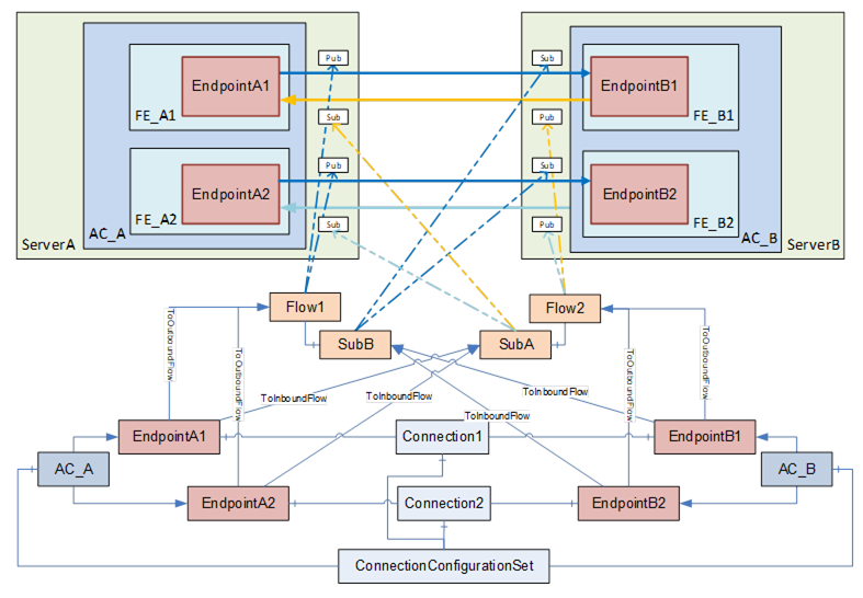
Figure E.2 – Multiple logical connections between two AutomationComponents
NOTE In this and the following figures, ServerAddress, HasCommunicationFlowConfiguration References, and PubSubCommunicationModelConfigurations are omitted for brevity. Refer to Figure E.1 for a complete view.
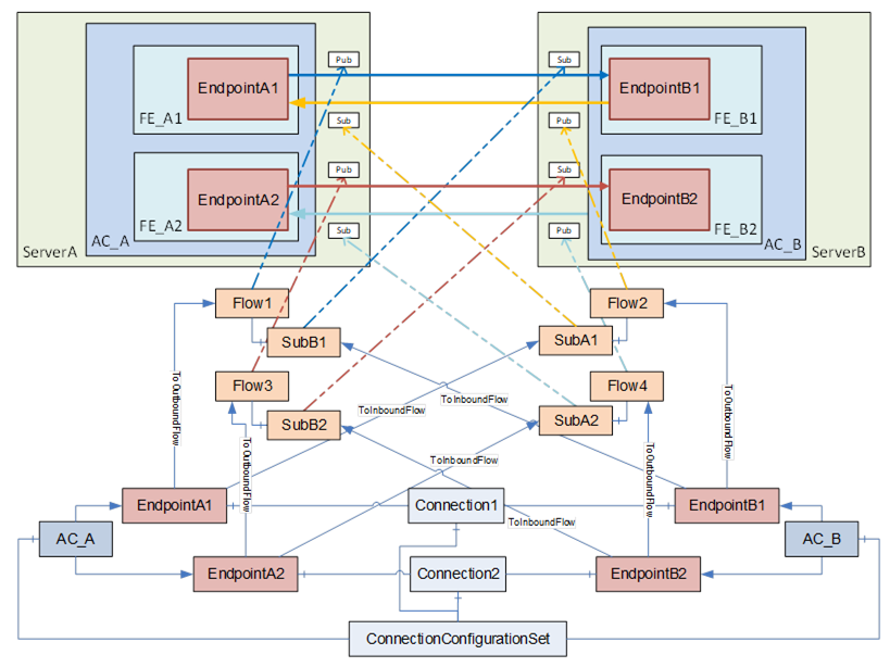
Figure E.3 – Multiple logical connections between two AutomationComponents (variant)
Figure E.4 depicts the configuration elements contained in a ConnectionConfigurationSet and their relation to each other for multiple logical connections among multiple AutomationComponents.
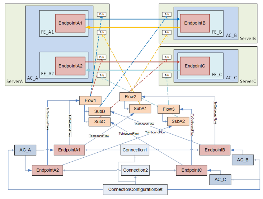
Figure E.4 – Multiple logical connections using multicast
This ConnectionConfigurationSet contains two ConnectionConfigurations, Connection1 and Connection2.
Since outbound traffic from AC_A is using multicast in this scenario, both EndpointA1 and EndpointA2 refer to PubSubCommunicationFlowConfiguration Flow1 with a ToOutboundFlow Reference. Flow1 contains two SubscriberConfigurations, SubB and SubC. This allows, for example, EndpointB and EndpointC to have different settings for the MessageReceiveTimeout. EndpointB and EndpointC refer to their specific Subscriber configuration with ToInboundFlow. If EndpointB and EndpointC do not require different SubscriberConfigurations, both endpoints could also refer to a single instance of SubscriberConfigurationType.
The unicast traffic in the opposite direction can also be modelled in various ways. The example shown in Figure E.4 allows different configuration settings for the unicast traffic with the PubSubCommunicationFlowConfiguration Flow2 and Flow3.
A variant is shown in Figure E.5, which shares the same set of parameters for the unicast Publishers and Subscribers.
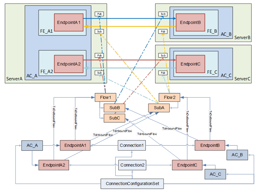
Figure E.5 – Multiple logical connections using multicast (variant)