The ConnectionManager processes ConnectionConfigurationSets to establish connections. This clause contains examples for ConnectionConfigurationSets. A ConnectionConfigurationSet contains a set of logical connections, which the ConnectionManager establishes as a complete set.
A ConnectionConfigurationSet can contain
- a single logical connection between two FunctionalEntities,
- multiple logical connections between FunctionalEntities located on two AutomationComponents,
- or multiple logical connections between FunctionalEntities located on multiple AutomationComponents.
The following examples illustrate the usage of ConnectionConfigurationSets. However, the usage of ConnectionConfigurationSets is not restricted to the examples.
Figure E.1 depicts the configuration elements contained in a ConnectionConfigurationSet and their relation to each other for a single logical connection. The relation between the configuration elements (present on the ConnectionManager) and their resulting runtime elements (present or created on the AutomationComponents being part of the logical connection) is indicated by dashed arrows.
+-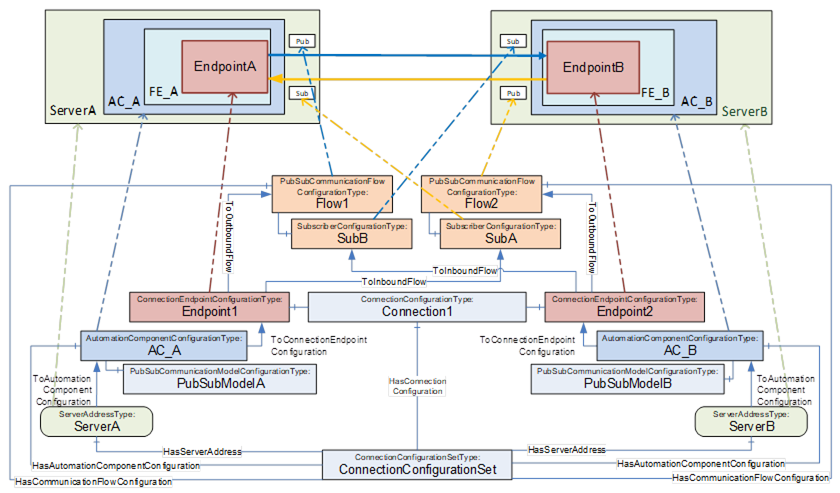
Figure E.1 – ConnectionConfigurationSet overview (single logical connection)
This ConnectionConfigurationSet contains one Connection configuration, Connection1, which contains the configuration for a single logical connection.
Connection1 contains two ConnectionEndpointConfigurations for the two ConnectionEndpoints EndpointA and EndpointB. Each ConnectionEndpointConfiguration contains all parameters required for creating the ConnectionEndpoint, verifying the affected FunctionalEntity, requesting ControlGroups, and application configuration.
The ConnectionConfigurationSet provides two PubSubCommunicationFlowConfiguration Objects, Flow1 and Flow2. They provide communication configuration (e.g., interval, timeout or QoS) and are referenced by the Endpoints with ToOutboundFlow and ToInboundFlow References. While an Object of type SubscriberConfigurationType (SubA, SubB) contains configuration for the Subscriber only, its parent PubSubCommunicationFlowConfigurationType Object contains configuration relevant for both the Publisher and Subscriber. The configuration contained in Flow1 is used for setting up the Publisher on ServerA, and the configuration contained in SubB and Flow1 is for setting up the Subscriber on ServerB. Flow2 and SubA are used for setting up the Publisher and Subscriber in the opposite direction.
EndpointA and EndpointB are each referenced by an AutomationComponentConfiguration, AC_A and AC_B, which hold the FunctionalEntities involved in this logical connection. AC_A and AC_B contain the parameters for verifying Assets. AC_A and AC_B could optionally include the PubSubCommunicationModelConfiguration, PubSubModelA and PubSubModelB.
AC_A and AC_B are each referenced by a ServerAddress, ServerA and ServerB, containing the configuration required for the ConnectionManager to be able to establish a secure Session to ServerA and ServerB.
Multiple logical connections can be configured between two or more AutomationComponents using unicast or multicast communication. Examples for each of the options are illustrated.
Figure E.2 depicts the configuration elements contained in a ConnectionConfigurationSet and their relation to each other for multiple logical connections between two AutomationComponents.
Often, traffic between two AutomationComponents will be optimised to use one NetworkMessage. EndpointA1 and EndpointA2 share PubSubCommunicationFlowConfiguration Flow1 with a ToOutboundFlow Reference and share SubscriberConfiguration SubA with a ToInboundFlow Reference to ensure the same set of parameters for the outbound and inbound NetworkMessage. The same applies to EndpointB1 and EndpointB2.
A variant of this scenario is illustrated in Figure E.3. In this example, one of the connections requires a fast PublishingInterval and Qos for the exchange of real-time data, and the other connection requires a slow PublishingInterval and best-effort for the exchange of status data.
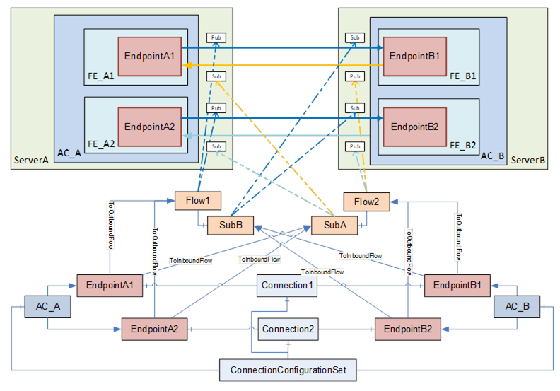
Figure E.2 – Multiple logical connections between two AutomationComponents
NOTE In this and the following figures, ServerAddress, HasCommunicationFlowConfiguration References, and PubSubCommunicationModelConfigurations are omitted for brevity. Refer to Figure E.1 for a complete view.
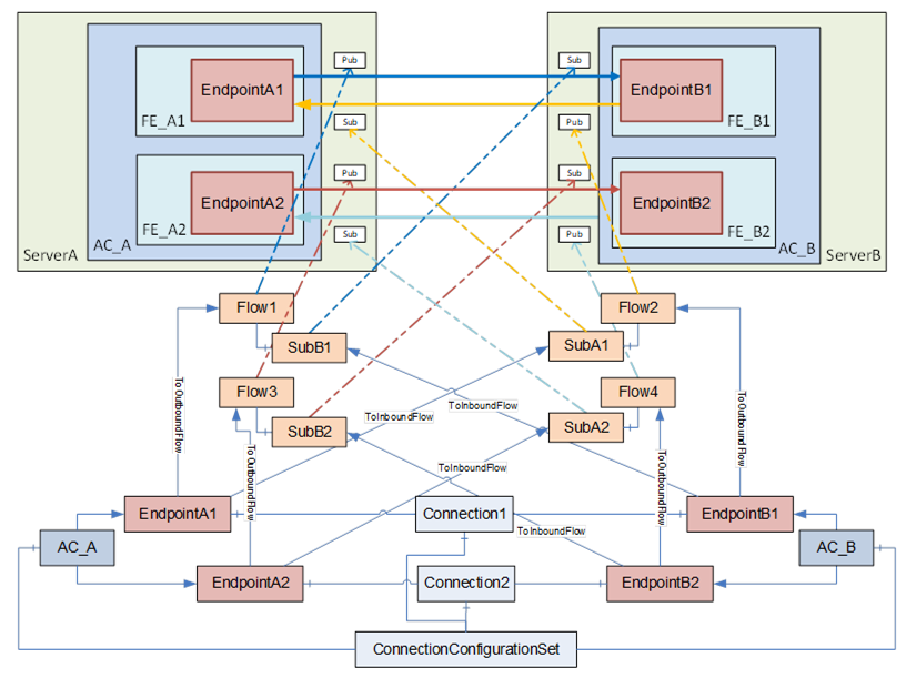
Figure E.3 – Multiple logical connections between two AutomationComponents (variant)
Figure E.4 depicts the configuration elements contained in a ConnectionConfigurationSet and their relation to each other for multiple logical connections among multiple AutomationComponents.
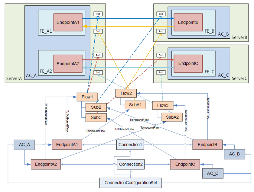
Figure E.4 – Multiple logical connections using multicast
This ConnectionConfigurationSet contains two ConnectionConfigurations, Connection1 and Connection2.
Since outbound traffic from AC_A is using multicast in this scenario, both EndpointA1 and EndpointA2 refer to PubSubCommunicationFlowConfiguration Flow1 with a ToOutboundFlow Reference. Flow1 contains two SubscriberConfigurations, SubB and SubC. This allows, for example, EndpointB and EndpointC to have different settings for the MessageReceiveTimeout. EndpointB and EndpointC refer to their specific Subscriber configuration with ToInboundFlow. If EndpointB and EndpointC do not require different SubscriberConfigurations, both endpoints could also refer to a single instance of SubscriberConfigurationType.
The unicast traffic in the opposite direction can also be modelled in various ways. The example shown in Figure E.4 allows different configuration settings for the unicast traffic with the PubSubCommunicationFlowConfiguration Flow2 and Flow3.
A variant is shown in Figure E.5, which shares the same set of parameters for the unicast Publishers and Subscribers.
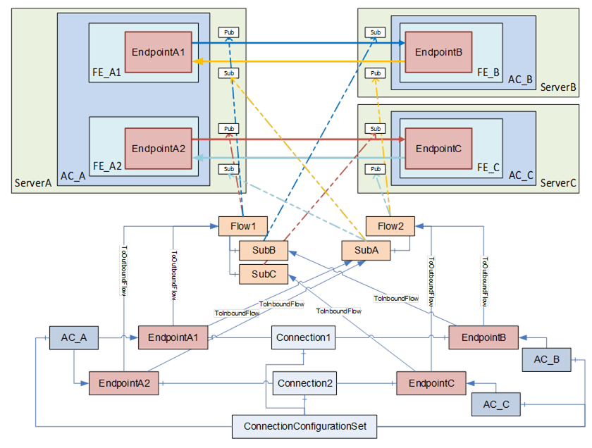
Figure E.5 – Multiple logical connections using multicast (variant)