
8 ObjectTypes for Vision System State Handling
8.1 State Machine overview
8.1.1 Introduction
All state machine types defined in this specification are mandatory unless explicitly stated otherwise. However, some states may be implemented as transient (do-nothing) states depending on the characteristics of the vision system.
To improve clarity and re-usability, this specification makes use of hierarchical state machines. This means that states of a state machine may have underlying SubStateMachines. The instantiation of a SubStateMachine for a particular state of the main state machine may be specified as optional.
8.1.2 Hierarchical state machines
8.1.2.1 Entering a SubStateMachine
OPC 10000-5, Annex B.4.9 defines several ways of entering a SubStateMachine:
If the SubStateMachine has an initial state (i.e., a state of type InitialStateType) this state is entered whenever the parent state is entered.
We make use of this principle for the VisionStepModelStateMachine defined in Section 8.4.
A SubStateMachine can also be entered by a direct transition from the parent state machine into one of its states, bypassing the initial state. In this case, the parent state machine goes automatically into the parent state of the SubStateMachine.
We make use of this principle for operation mode state machines like the VisionAutomaticModeStateMachine defined in Section 8.3.
If a SubStateMachine has no initial state and the parent state is entered directly, the state of the SubStateMachine is server-specific.
We make use of this principle for the error handling described in Section 8.2.2.4.
8.1.2.2 Leaving a SubStateMachine
The SubStateMachine types used here do not have transitions into specific states of the parent state machine so that they are not bound to a specific state machine, but can be used within states of any state machine. Therefore, the SubStateMachines are not left explicitly. Instead, the parent state machine may leave the parent state of the SubStateMachine in which case the SubStateMachine ceases to be active and will enter a Bad_StateNotActive state. In that case, the system actually transitions from a state of the SubStateMachine into an unrelated state of the main state machine, but this transition will not be explicitly shown or specified on the level of the SubStateMachine.
We make use of that principle especially for the error handling described in Section 8.2.2.4.
At present, this specification describes one such mode, the “Automatic” mode. All pertaining states are contained in a SubStateMachine of type VisionAutomaticModeStateMachine defined in Section VisionAutomaticModeStateMachineType. The reason for this naming is that this state machine is derived – but not restricted to – the typical application of a vision system in automatic operation on a production line.State machine type hierarchy
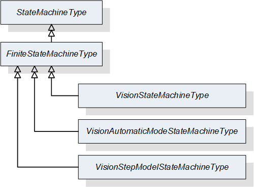
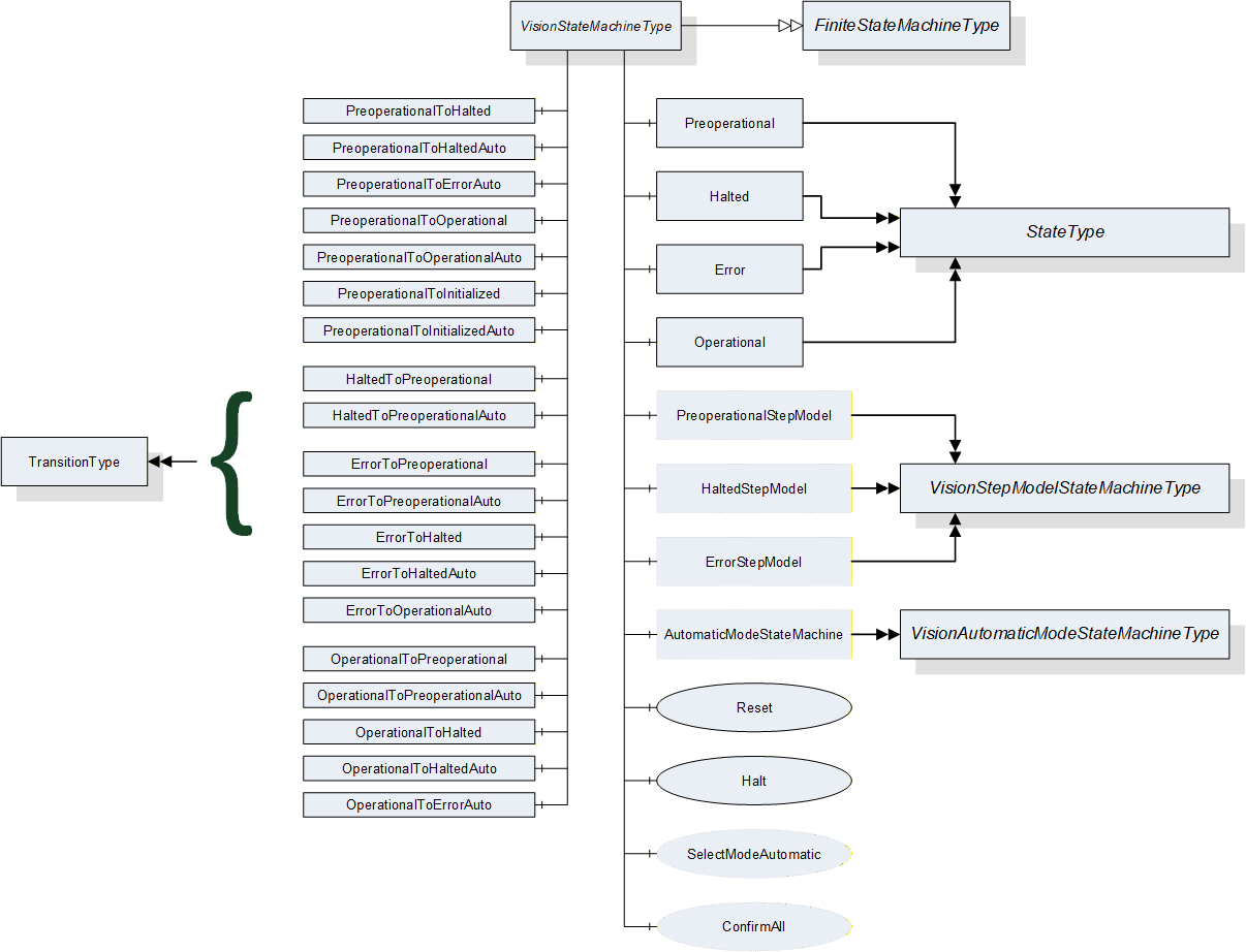
The following diagram shows the hierarchy of mandatory state machine types in this specification. All state machine types are derived from the FiniteStateMachineType, implying that all their states and transitions are pre-defined and cannot be changed or added to by sub-typing so that a client can detect all states and transitions and rely on these and only these states and transitions to exist on sub-types of the state machine type
8.1.3 Automatic and triggered transitions and events
In the state machines specified here, most transitions can be caused by method calls and all transitions can be caused by internal decisions of the vision system. We call these “automatic” transitions.
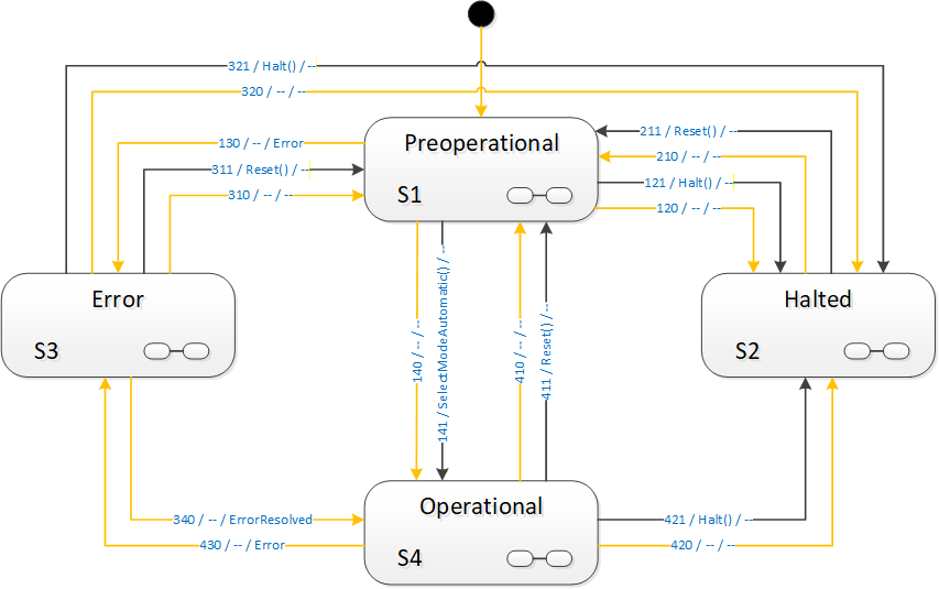
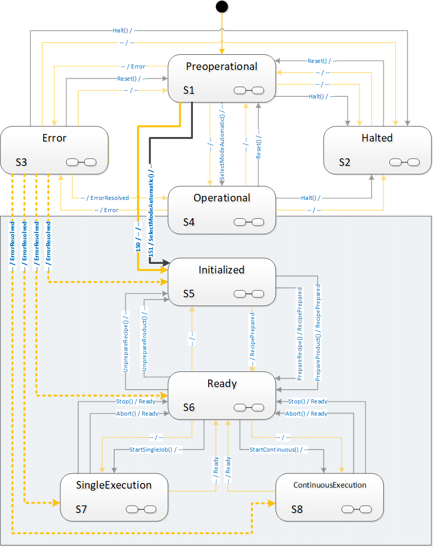
In the state diagrams describing the state machines in the following sections, all transitions are shown individually. Transitions caused by methods are shown in black with the method name as the UML transition trigger. “Automatic” transitions are shown in orange without a trigger.
Upon entry into a new state, a StateChanged Event will be triggered indicating the transition.
Some transitions may trigger extra events. These events are shown in the state diagrams on the transition as a UML effect, preceded by a “/”.
Some transitions may depend on conditions. Where they are semantically important, they have been put into the state diagrams as UML guards in “[]”.
8.1.4 Preventing transitions
The server can prevent transitions from being carried out, e.g. due to the internal state of the vision system. A typical example would be to prevent leaving the parent state of a VisionStepModelStateMachine in order to avoid interrupting synchronization with an external system.
As automatic transitions are always done for internal reasons, the server will obviously simply not execute the transition in this case.
For method-triggered transitions, the server should set the Executable flag of the method in question to False to signal to clients that this method should currently not be called. If the method is called anyway, regardless of the Executable flag, the method shall fail with an appropriate error code.
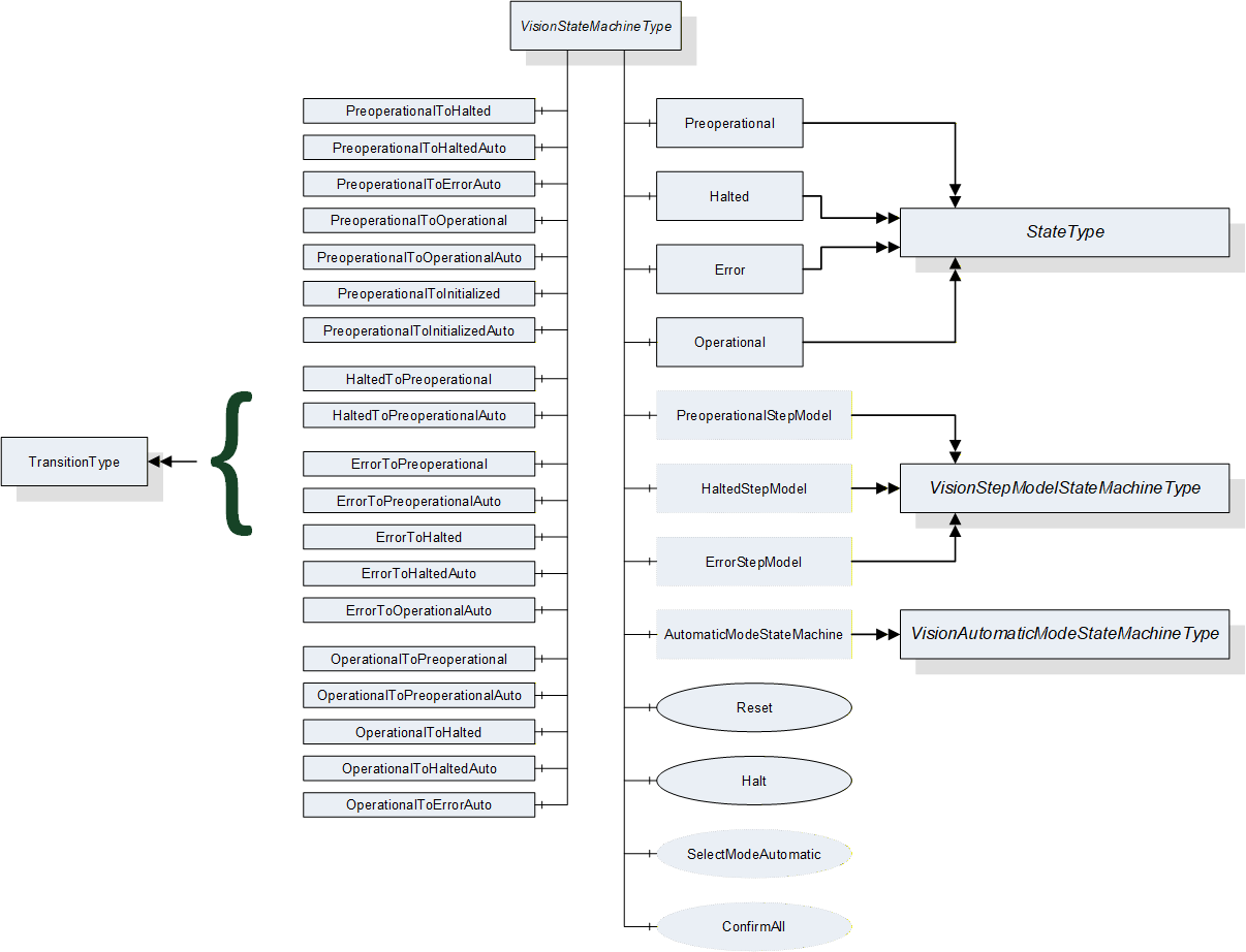
8.2 VisionStateMachineType
8.2.1 Introduction
This ObjectType is a subtype of FiniteStateMachineType and represents the top-level behavior of the vision system. It is formally defined in Table 81.
The Operational state has a mandatory SubStateMachine for the “Automatic” mode of operation and may have additional SubStateMachines for other modes of operation.
The other state may have optional SubStateMachines of the VisionStepModelStateMachineType.
For clarity, transitions into states of SubStateMachines are not shown in the diagram.
8.2.2 Operation of the VisionStateMachineType
8.2.2.1 Basic operation
After power-up the system goes into a Preoperational state. It is assumed that the vision system loads a configuration which is present on the system and marked as active. From there, it can be put into Operational state either automatically, due to internal initialization processes or by a SelectMode method call. The VisionStateMachineType provides one mandatory method, SelectModeAutomatic for transition into the “Automatic” mode SubStateMachine described in Section 8.3. Subtypes of VisionStateMachineType may offer additional SubStateMachines and thus additional SelectMode method calls.
The system stays in Operational mode, doing its job, until it is either resetted, halted or an error occurs which suspends normal operation until resolved.
8.2.2.2 Resetting the system
At any time, it may be necessary or desired to revert the vision system into its initial state after power-up, i.e., state Preoperational.
The vision system may decide this due to internal conditions, or by calling the Reset method on the VisionStateMachine in the OPC UA server.
The Reset method shall always be executable. If for some reason the vision system is not capable of carrying out this transition, the behavior is undefined. The underlying assumption is that, if the vision system cannot perform a reset, it cannot be assumed that it is capable of carrying out any other controlled transition, including a transition into the Error state.
Application Note:
There are basically two reasons for a reset in the state model of this specification.
Either the vision system is idle – reflected by, e.g. the Ready or Initialized state – and the intent of calling the Reset method is to return to Preoperational state in order to call a different SelectMode method to change the mode of operation. In that case, carrying out the transition should not be a problem.
The other situation is as an emergency measure because the vision system does no longer operate correctly. In that case, the method may fail with an internal error code like Bad_UnexpectedError or Bad_InvalidState, but since the vision system is in an incorrect internal state, it is uncertain that it can reach any other state, like Error.
The client can assume that Preoperational or Error states should be reached within a reasonable – application-specific – time-frame. If that is not the case, the client can conclude that intervention is necessary and issue an appropriate message and operator call.
8.2.2.3 Halting the system
A vision system will frequently make use of a number of resources, like camera drivers, files, databases etc. which will need to be properly closed before shutting down that system.
In Halted state, the system shall have put all resources into a state where it is safe to power down the system. However, not all operation is stopped, because the system can be brought out of Halted state by a call to the Reset method, transitioning to the Preoperational state.
The vision system may decide to enter Halted state due to internal conditions or by calling the Halt method on the OPC UA server.
The Halt method shall always be executable. If for some reason the system is not capable of carrying out the transition, the VisionStateMachine shall transition into the Error state.
8.2.2.4 Error handling
In every state of the VisionStateMachine or any of its SubStateMachines, an error may occur.
The system may also decide to enter state Error by means of an automatic operation if it cannot – or should not – continue its normal operation in the presence of an error. Note that the presence of an error condition does not necessarily cause the system to enter the Error state, it may be capable to continue normal operation in the presence of a signaled error condition. However, it the system does enter the Error state, it is mandatory that it indicates this by activating an error condition.
An error shall be signaled by an appropriate error condition. An arbitrary number of error conditions can be active at any time.
Error conditions are exposed as subtypes of the ConditionType defined in OPC 10000-9 and may have Acknowledge and Confirm methods and the appropriate state handling. It is expected that the calling of these methods has an effect upon the underlying system and/or that the underlying vision system monitors the state of the conditions and uses these in its internal decision making process whether to stay in the Error state or in which state to transition next.
It is assumed that the Acknowledge method will typically be called by a client automatically, indicated that the message has at least been received. The Confirm method will typically be caused by a human interaction, confirming that the cause of the error is remedied.
For convenience, the VisionStateMachine may offer the ConfirmAll method which shall confirm all conditions currently active. The effect on the internal decision making shall be the same as when the methods would have been called individually from the outside.
Thus, in Error state, the system decides either on its own or based on external input, like an acknowledgement or confirmation of the error, and other (non OPC UA) input signals, which state to transition to next.
Upon entering the Error state, an event of type ErrorEventType is triggered, upon leaving to some other state, an ErrorResolved event is triggered, if the error is actually resolved, in addition to the mandatory StateChanged events. Thus, a control system may listen only to the Error and ErrorResolved events monitoring the vision system.
The Error state can be left in the following ways:
By a call to the Halt or Reset method, transitioning to states Halted and Preoperational respectively. The condition(s) causing the Error state do not necessarily have to be resolved for this transition. Only if they are resolved, an ErrorResolvedEvent shall be triggered.
By an internal decision of the system to transition into the Halted or Preoperational states. As these states do not constitute normal productive operation of the system, the condition(s) causing the Error state do not necessarily have to be resolved for this transition. Only if they are resolved, an ErrorResolved event shall be triggered. Subsequent action, e.g. a call to ActivateConfiguration in these states may lead to the error being resolved and the system being capable of resuming normal productive operation.
By an internal decision of the system to transition into the Operational state. As this state constitutes normal productive operation, this transition is only allowed if the condition(s) leading to the Error state are actually resolved. Therefore, an ErrorResolved event shall be triggered in this case.
In the last case, the automatic transition into the Operational state due to the resolving of the error condition(s), the system will actually go into one of the states of the SubStateMachines of the Operational state, using the 3rd method for entering a SubStateMachine described in Section 8.1.2.1 by a server-specific decision about the state.
Thus, the vision system can decide, based on its internal conditions, in which actual state it will continue operation. It may decide that it can immediately continue a job interrupted by the error and return to the SingleExecution or ContinuousExecution states; it may decide that it can immediately take on the next job and return to the Ready state; it may decide that it needs a re-initialization of a recipe and return to the Initialized state. It may even decide that it can resume a synchronization with an external system and return to any state within a VisionStepModelStateMachine inside one of these states.
8.2.3 VisionStateMachineType Overview
8.2.4 Modes of operation
One underlying idea of this specification is that a vision system may have different modes of operation with very different sets of states, methods and transitions.
Due to the high degree of individuality of vision system requirements and solutions, it does not appear possible to standardize each and every mode of operation of such systems. Therefore, vision systems according to this specification are free to implement additional state machines for such use cases.
However, this specification considers some states as universal for machine vision systems according to this specification and thus outside of these modes of operation, namely states related to powering up and shutting down the system and to error handling.
The system will in any case need to power up and enter some state automatically without outside intervention. From this state, a selection – either by method call or automatically based on internal and external circumstances – of the actual mode of operation can be made.
Conversely, the same holds for shutting down the system. Independent from the mode of operation, the system will need a way to enter a state from which it can safely be powered down.
And finally it will be of great advantage to all clients if the handling of errors is identical in all modes of operation.
Therefore, these states are mandatory in this specification as well as one state encompassing the actual operation of the system. Modes of operation shall be specified as SubStateMachines to this operational state.
8.2.5 VisionStateMachineType Definition
VisionStateMachineType is formally defined in Table 81.
| Attribute | Value | ||||
| Includes all attributes specified for the FiniteStateMachineType | |||||
| BrowseName | VisionStateMachineType | ||||
| IsAbstract | False | ||||
| References |
Node
Class | BrowseName | DataType | TypeDefinition | ModellingRule |
|---|---|---|---|---|---|
| Subtype of the FiniteStateMachineType defined in OPC 10000-5 Annex B.4.5 | |||||
| HasComponent | Object | Preoperational | -- | StateType | |
| HasComponent | Object | Halted | -- | StateType | |
| HasComponent | Object | Error | -- | StateType | |
| HasComponent | Object | Operational | -- | StateType | |
| HasComponent | Object | PreoperationalToHalted | -- | TransitionType | |
| HasComponent | Object | PreoperationalToHaltedAuto | -- | TransitionType | |
| HasComponent | Object | PreoperationalToErrorAuto | -- | TransitionType | |
| HasComponent | Object | PreoperationalToOperational | -- | TransitionType | |
| HasComponent | Object | PreoperationalToOperationalAuto | -- | TransitionType | |
| HasComponent | Object | PreoperationalToInitialized | -- | TransitionType | |
| HasComponent | Object | PreoperationalToInitializedAuto | -- | TransitionType | |
| HasComponent | Object | HaltedToPreoperational | -- | TransitionType | |
| HasComponent | Object | HaltedToPreoperationalAuto | -- | TransitionType | |
| HasComponent | Object | ErrorToPreoperational | -- | TransitionType | |
| HasComponent | Object | ErrorToPreoperationalAuto | -- | TransitionType | |
| HasComponent | Object | ErrorToHalted | -- | TransitionType | |
| HasComponent | Object | ErrorToHaltedAuto | -- | TransitionType | |
| HasComponent | Object | ErrorToOperationalAuto | -- | TransitionType | |
| HasComponent | Object | OperationalToPreoperational | -- | TransitionType | |
| HasComponent | Object | OperationalToPreoperationalAuto | -- | TransitionType | |
| HasComponent | Object | OperationalToHalted | -- | TransitionType | |
| HasComponent | Object | OperationalToHaltedAuto | -- | TransitionType | |
| HasComponent | Object | OperationalToErrorAuto | -- | TransitionType | |
| HasComponent | Method | Reset | -- | -- | Mandatory |
| HasComponent | Method | Halt | -- | -- | Mandatory |
| HasComponent | Method | SelectModeAutomatic | -- | -- | Optional |
| HasComponent | Method | ConfirmAll | -- | -- | Optional |
| HasComponent | Object | PreoperationalStepModel | -- | VisionStepModelStateMachineType | Optional |
| HasComponent | Object | HaltedStepModel | -- | VisionStepModelStateMachineType | Optional |
| HasComponent | Object | ErrorStepModel | -- | VisionStepModelStateMachineType | Optional |
| HasComponent | Object | AutomaticModeStateMachine | -- | VisionAutomaticModeStateMachineType | Optional |
8.2.6 VisionStateMachineType States
8.2.6.1 Introduction
Table 82 specifies the VisionStateMachine’s state Objects. These state Objects are instances of the StateType defined in OPC 10000-5 – Annex B. Each state is assigned a unique StateNumber value. Subtypes of the VisionStateMachineType can add References from any state to a subordinate or nested StateMachine Object to extend the FiniteStateMachine. See Table 83 for a brief description of the states.
| BrowseName | References | Target BrowseName | Value | Target TypeDefinition | Notes |
| Preoperational | HasProperty | StateNumber | 1 | PropertyType | -- |
| FromTransition | HaltedToPreoperational | TransitionType | -- | ||
| FromTransition | HaltedToPreoperationalAuto | TransitionType | -- | ||
| FromTransition | ErrorToPreoperationalAuto | TransitionType | -- | ||
| FromTransition | ErrorToPreoperational | TransitionType | -- | ||
| FromTransition | OperationalToPreoperational | TransitionType | -- | ||
| FromTransition | OperationalToPreoperationalAuto | TransitionType | -- | ||
| ToTransition | PreoperationalToHalted | TransitionType | -- | ||
| ToTransition | PreoperationalToHaltedAuto | TransitionType | -- | ||
| ToTransition | PreoperationalToErrorAuto | TransitionType | -- | ||
| ToTransition | PreoperationalToOperational | TransitionType | -- | ||
| ToTransition | PreoperationalToOperationalAuto | TransitionType | -- | ||
| ToTransition | PreoperationalToInitialized | TransitionType | -- | ||
| ToTransition | PreoperationalToInitializedAuto | TransitionType | -- | ||
| HasSubStateMachine | PreoperationalStepModel | VisionStepModelState MachineType | -- | ||
| Halted | HasProperty | StateNumber | 2 | PropertyType | -- |
| FromTransition | PreoperationalToHalted | TransitionType | -- | ||
| FromTransition | PreoperationalToHaltedAuto | TransitionType | -- | ||
| FromTransition | ErrorToHalted | TransitionType | -- | ||
| FromTransition | ErrorToHaltedAuto | TransitionType | -- | ||
| FromTransition | OperationalToHalted | TransitionType | -- | ||
| FromTransition | OperationalToHaltedAuto | TransitionType | -- | ||
| ToTransition | HaltedToPreoperational | TransitionType | -- | ||
| ToTransition | HaltedToPreoperationalAuto | TransitionType | -- | ||
| HasSubStateMachine | HaltedStepModel | VisionStepModelState MachineType | -- | ||
| Error | HasProperty | StateNumber | 3 | PropertyType | -- |
| FromTransition | PreoperationalToErrorAuto | TransitionType | -- | ||
| FromTransition | OperationalToErrorAuto | TransitionType | -- | ||
| ToTransition | ErrorToPreoperational | TransitionType | -- | ||
| ToTransition | ErrorToPreoperationalAuto | TransitionType | -- | ||
| ToTransition | ErrorToHalted | TransitionType | -- | ||
| ToTransition | ErrorToHaltedAuto | TransitionType | -- | ||
| ToTransition | ErrorToOperationalAuto | TransitionType | -- | ||
| HasSubStateMachine | ErrorStepModel | VisionStepModelState MachineType | -- | ||
| Operational | HasProperty | StateNumber | 4 | PropertyType | -- |
| FromTransition | PreoperationalToOperational | TransitionType | -- | ||
| FromTransition | PreoperationalToOperationalAuto | TransitionType | -- | ||
| FromTransition | ErrorToOperationalAuto | TransitionType | -- | ||
| ToTransition | OperationalToPreoperational | TransitionType | -- | ||
| ToTransition | OperationalToPreoperationalAuto | TransitionType | -- | ||
| ToTransition | OperationalToHalted | TransitionType | -- | ||
| ToTransition | OperationalToHaltedAuto | TransitionType | -- | ||
| ToTransition | OperationalToErrorAuto | TransitionType | -- | ||
| HasSubStateMachine | AutomaticModeStateMachine | VisionAutomaticModeState MachineType | -- |
The brief state descriptions in Table 83 will be detailed in the following subsections.
| StateName | Description |
| Preoperational | This is the initial state of the system after power-up and the state after a Reset method call. From here the system has to be brought into Operational state by selecting a mode of operation. Alternatively it can be halted. |
| Halted | This state is intended as the final state in the operation of the system. All resources shall be in a state allowing for safe power-down. However, the system can be put back into operation by a Reset method call, going through the Preoperational state. |
| Error | This state intended for the indication and resolution of errors preventing normal operation of the system. |
| Operational | This is the state for normal operation of the system. It is always a composite state with the SubStateMachine modelling the current mode of operation. This specification describes only a single mode of operation, the “Automatic” mode, described in 8.3. Vendors can add other modes of operation by sub-typing VisionStateMachineType and adding other SubStateMachines for these modes of operation. See Section 8.3.9 for implementation remarks. |
8.2.6.2 Preoperational State
In this state, the system is characterized by the following properties:
System is powered on, this is the initial state after power on
No recipes are loaded
No mode of operation is selected
No error is detected
This state shall be entered automatically upon startup.
If an error is detected, the system shall transit to the Error state.
This state can be entered from any state, either by an automatic transition or caused by calling the Reset method.
From this state, all other states on this level can be reached, either by an automatic transition or by calling the Halt method for the Halted state or the SelectModeAutomatic method for sub-state Initialized of the Automatic mode SubStateMachine of state Operational. (see 8.3 for the description of the Automatic mode SubStateMachine and see 8.3.9 for implementation remarks on state machines derived from VisionStateMachineType for other modes of operation) or other SelectMode methods for other, vendor-specific, sub state machines of the Operational state.
This state can be a composite state with an optional VisionStepModelStateMachineType SubStateMachine.
8.2.6.3 Halted State
In this state, the system is characterized by the following properties:
The system has stopped all operations
The system can safely be powered down (e.g. all files are closed; all resources are released, …)
The OPC UA server shall still be running to allow for a transition to state Preoperational.
This state can be reached from any other state either by an automatic transition or by calling the Halt method. Calling the Halt method in this state will not have an effect.
From this state, only Preoperational state can be reached, either by an automatic transition or by calling the Reset method.
This state can be a composite state with an optional VisionStepModelStateMachineType SubStateMachine.
8.2.6.4 Error State
In this state, the system is characterized by the following properties:
An error has occurred which disrupts normal operation.
The system issues messages (in the form of Conditions) informing clients about the error; it awaits acknowledgement of these messages, i.e., the information that some client has received the message, and optionally confirmation, i.e., the information that some corrective action has been taken, typically by human intervention.
The system tries to resolve the error by internal means taking into account the (mandatory) acknowledgement and (optional) confirmation of the messages issued.
This state can be entered from any other state by an automatic transition due to an error detected by the system.
This state can be left by an automatic transition based on the result of the error resolution into any other state, or into Preoperational state by a Reset method call or into Halted state by a Halt method call, provided the requirements on Acknowledgement and Confirmation have been fulfilled. For details on signaling error conditions and on error resolution behavior see Section 11.4.6.
This state can be a composite state with an optional VisionStepModelStateMachineType SubStateMachine.
8.2.6.5 Operational State
State Operational is a composite state with a mandatory VisionAutomaticModeStateMachineType SubStateMachine.
In this state, the system is characterized by the following properties:
The system has been initialized so far that the normal operation intended for the given mode of operation can be carried out as well as various system management functions.
The system has not detected an error preventing it from carrying out this operation (by transitioning into state Error).
The system is in any of the states of the VisionAutomaticModeStateMachineType, carrying out its normal operation, or in a state of another state machine added by the vendor as an additional SubStateMachine of state Operational.
8.2.7 VisionStateMachineType Transitions
Transitions are instances of Objects of the TransitionType defined in OPC 10000-5 – Annex B which also includes the definitions of the ToState, FromState, HasCause, and HasEffect References used. Table 84 specifies the Transitions defined for the VisionStateMachineType. Each Transition is assigned a unique TransitionNumber.
| BrowseName | References | Target BrowseName | Value | Target TypeDefinition | Notes |
| PreoperationalToHalted | HasProperty | TransitionNumber | 121 | PropertyType | -- |
| FromState | Preoperational | StateType | -- | ||
| ToState | Halted | StateType | -- | ||
| HasCause | Halt | Method | -- | ||
| HasEffect | StateChangedEventType | -- | |||
| PreoperationalToHaltedAuto | HasProperty | TransitionNumber | 120 | PropertyType | -- |
| FromState | Preoperational | StateType | -- | ||
| ToState | Halted | StateType | -- | ||
| HasEffect | StateChangedEventType | -- | |||
| PreoperationalToErrorAuto | HasProperty | TransitionNumber | 130 | PropertyType | -- |
| FromState | Preoperational | StateType | -- | ||
| ToState | Error | StateType | -- | ||
| HasEffect | StateChangedEventType | -- | |||
| HasEffect | ErrorEventType | -- | |||
| PreoperationalToOperational | HasProperty | TransitionNumber | 141 | PropertyType | -- |
| FromState | Preoperational | StateType | -- | ||
| ToState | Operational | StateType | -- | ||
| HasCause | SelectModeAutomatic | Method | -- | ||
| HasEffect | StateChangedEventType | -- | |||
| PreoperationalToOperationalAuto | HasProperty | TransitionNumber | 140 | PropertyType | -- |
| FromState | Preoperational | StateType | -- | ||
| ToState | Operational | StateType | -- | ||
| HasEffect | StateChangedEventType | -- | |||
| PreoperationalToInitialized | HasProperty | TransitionNumber | 151 | PropertyType | -- |
| FromState | Preoperational | StateType | -- | ||
| ToState | AutomaticModeStateMachine.Initialized | StateType | -- | ||
| HasCause | SelectModeAutomatic | Method | -- | ||
| HasEffect | StateChangedEventType | -- | |||
| PreoperationalToInitializedAuto | HasProperty | TransitionNumber | 150 | PropertyType | -- |
| FromState | Preoperational | StateType | -- | ||
| ToState | AutomaticModeStateMachine.Initialized | StateType | -- | ||
| HasEffect | StateChangedEventType | -- | |||
| HaltedToPreoperational | HasProperty | TransitionNumber | 211 | PropertyType | -- |
| FromState | Halted | StateType | -- | ||
| ToState | Preoperational | StateType | -- | ||
| HasCause | Reset | Method | -- | ||
| HasEffect | StateChangedEventType | -- | |||
| HaltedToPreoperationalAuto | HasProperty | TransitionNumber | 210 | PropertyType | -- |
| FromState | Halted | StateType | -- | ||
| ToState | Preoperational | StateType | -- | ||
| HasEffect | StateChangedEventType | -- | |||
| ErrorToPreoperational | HasProperty | TransitionNumber | 311 | PropertyType | -- |
| FromState | Error | StateType | -- | ||
| ToState | Preoperational | StateType | -- | ||
| HasCause | Reset | Method | -- | ||
| HasEffect | StateChangedEventType | -- | |||
| ErrorToPreoperationalAuto | HasProperty | TransitionNumber | 310 | PropertyType | -- |
| FromState | Error | StateType | -- | ||
| ToState | Preoperational | StateType | -- | ||
| HasEffect | StateChangedEventType | ||||
| ErrorToHalted | HasProperty | TransitionNumber | 321 | PropertyType | -- |
| FromState | Error | StateType | -- | ||
| ToState | Halted | StateType | -- | ||
| HasCause | Halt | Method | -- | ||
| HasEffect | StateChangedEventType | -- | |||
| ErrorToHaltedAuto | HasProperty | TransitionNumber | 320 | PropertyType | -- |
| FromState | Error | StateType | -- | ||
| ToState | Halted | StateType | -- | ||
| HasEffect | StateChangedEventType | -- | |||
| ErrorToOperationalAuto | HasProperty | TransitionNumber | 340 | PropertyType | -- |
| FromState | Error | StateType | -- | ||
| ToState | Operational | StateType | -- | ||
| HasEffect | StateChangedEventType | -- | |||
| HasEffect | ErrorResolvedEventType | -- | |||
| OperationalToPreoperational | HasProperty | TransitionNumber | 411 | PropertyType | -- |
| FromState | Operational | StateType | -- | ||
| ToState | Preoperational | StateType | -- | ||
| HasCause | Reset | Method | -- | ||
| HasEffect | StateChangedEventType | -- | |||
| OperationalToPreoperationalAuto | HasProperty | TransitionNumber | 410 | PropertyType | -- |
| FromState | Operational | StateType | -- | ||
| ToState | Preoperational | StateType | -- | ||
| HasEffect | StateChangedEventType | -- | |||
| OperationalToHalted | HasProperty | TransitionNumber | 421 | PropertyType | -- |
| FromState | Operational | StateType | -- | ||
| ToState | Halted | StateType | -- | ||
| HasCause | Halt | Method | -- | ||
| HasEffect | StateChangedEventType | -- | |||
| OperationalToHaltedAuto | HasProperty | TransitionNumber | 420 | PropertyType | -- |
| FromState | Operational | StateType | -- | ||
| ToState | Halted | StateType | -- | ||
| HasEffect | StateChangedEventType | -- | |||
| OperationalToErrorAuto | HasProperty | TransitionNumber | 430 | PropertyType | -- |
| FromState | Operational | StateType | -- | ||
| ToState | Error | StateType | -- | ||
| HasEffect | StateChangedEventType | -- |
8.2.8 VisionStateMachineType Methods
8.2.8.1 Halt method
This method commands the system to go into the Halted state from where it is safe to power down the system without damage to system resources (like files, data bases, etc.); what the system does during this transition and how long it takes, is application-defined and may depend on the parameter given to the Halt method (e.g. to distinguish between a fast shutdown due to power-loss or a more gentle shutdown completing ongoing evaluations).
Signature
Halt ([in] Int32 cause[in] String causeDescription[out] Int32 error);
| Argument | Description |
| cause | Implementation-specific number denoting the reason for the Halt method call. |
| causeDescription | Text for said reason, e.g. for logging purposes. May be empty. |
| error | 0 – OK Values > 0 are reserved for errors defined by this and future standards. Values < 0 shall be used for application-specific errors. |
| Attribute | Value | ||||
| BrowseName | Halt | ||||
| References | NodeClass | BrowseName | DataType | TypeDefinition | ModellingRule |
|---|---|---|---|---|---|
| HasProperty | Variable | InputArguments | Argument[] | PropertyType | Mandatory |
| HasProperty | Variable | OutputArguments | Argument[] | PropertyType | Mandatory |
The cause argument given to the method can only be interpreted by the underlying vision system It can be used, for example, for logging purposes. It is expected that a value of 0 will be considered an “unspecified reason”.
8.2.8.2 Reset method
This method commands the system to return to the Preoperational state where it has not parameterization for carrying out jobs (single or continuous), e.g. to reset the state of recipes; what the system does during this transition and how long it takes, is application-defined and may depend on the parameter given to the Reset method (e.g. to distinguish between a fast emergency reset due to an error or safety condition or a more gentle reset completing ongoing evaluations).
Signature
Reset ([in] Int32 cause[in] String causeDescription[out] Int32 error);
| Argument | Description |
| cause | Implementation-specific number denoting the reason for the Reset method call. |
| causeDescription | Text for said reason, e.g. for logging purposes. . May be empty. |
| error | 0 – OK Values > 0 are reserved for errors defined by this and future standards. Values < 0 shall be used for application-specific errors. |
| Attribute | Value | ||||
| BrowseName | Reset | ||||
| References | NodeClass | BrowseName | DataType | TypeDefinition | ModellingRule |
|---|---|---|---|---|---|
| HasProperty | Variable | InputArguments | Argument[] | PropertyType | Mandatory |
| HasProperty | Variable | OutputArguments | Argument[] | PropertyType | Mandatory |
The Cause argument given to the method can only be interpreted by the underlying vision system It can be used, for example, for logging purposes. It is expected that a value of 0 will be considered an “unspecified reason”.
8.2.8.3 SelectModeAutomatic method
This method commands the system to enter the mandatory AutomaticModeStateMachine attached to Operational state, or, more precisely, the Initialized state of that SubStateMachine.
Signature
SelectModeAutomatic ([out] Int32 error);
| Argument | Description |
| error | 0 – OK Values > 0 are reserved for errors defined by this and future standards. Values < 0 shall be used for application-specific errors. |
| Attribute | Value | ||||
| BrowseName | SelectModeAutomatic | ||||
| References | NodeClass | BrowseName | DataType | TypeDefinition | ModellingRule |
|---|---|---|---|---|---|
| HasProperty | Variable | OutputArguments | Argument[] | PropertyType | Mandatory |
8.2.8.4 ConfirmAll method
With this method, a client can confirm all currently active conditions of the server derived from VisionConditionType. In analogy to the Confirm method of the AcknowledgeableConditionType it expects a LocalizedText as a comment, not, however an EventId as this would not make sense for multiple events.
Signature
ConfirmAll ([in] LocalizedText comment);
| Argument | Description |
| Comment | A localized text to be applied to the conditions. |
| Attribute | Value | ||||
| BrowseName | ConfirmAll | ||||
| References | NodeClass | BrowseName | DataType | TypeDefinition | ModellingRule |
|---|---|---|---|---|---|
| HasProperty | Variable | InputArguments | Argument[] | PropertyType | Mandatory |
8.2.9 VisionStateMachineType EventTypes
8.2.9.1 StateChangedEventType
StateChangedEventType is an EventType subtype of TransitionEventType, defined in OPC 10000-5. This event shall be triggered by the server whenever the system enters a new state.It is formally defined in Table 93. The event transports the NodeId of the state entered as well as the transition which is leading into that state.
| Attribute | Value | ||||
| BrowseName | StateChangedEventType | ||||
| IsAbstract | False | ||||
| References | NodeClass | BrowseName | DataType | TypeDefinition | ModellingRule |
|---|---|---|---|---|---|
| Subtype of the TransitionEventType defined in OPC 10000-5 | |||||
Refer to the TransitionEventType in OPC 10000-5 for the behavior and the transported information.
8.2.9.2 ErrorEventType
ErrorEventType is an EventType subtype of TransitionEventType, defined in OPC 10000-5. This event must be triggered when the vision system decides that the current conditions require it to suspend normal operation and enter state Error. Additional detail about the circumstances leading to the Error state shall be indicated by active ConditionType events. For more detail see Section 11.
It is formally defined in Table 94.
| Attribute | Value | ||||
| BrowseName | ErrorEventType | ||||
| IsAbstract | False | ||||
| References | NodeClass | BrowseName | DataType | TypeDefinition | ModellingRule |
|---|---|---|---|---|---|
| Subtype of the TransitionEventType defined in OPC 10000-5 | |||||
8.2.9.3 ErrorResolvedEventType
ErrorResolvedEventType is an EventType subtype of TransitionEventType, defined in OPC 10000-5. This event must be triggered when the vision system decides that the current conditions do not require state Error to be maintained and initiates the transition into whatever state it deemed appropriate under the circumstances.
It is formally defined in Table 95.
| Attribute | Value | ||||
| BrowseName | ErrorResolvedEventType | ||||
| IsAbstract | False | ||||
| References | NodeClass | BrowseName | DataType | TypeDefinition | ModellingRule |
|---|---|---|---|---|---|
| Subtype of the TransitionEventType defined in OPC 10000-5 | |||||
8.3 VisionAutomaticModeStateMachineType
8.3.1 Introduction
VisionAutomaticModeStateMachineType is an ObjectType subtype of FiniteStateMachineType and represents the behavior of a vision system in automatic operation.
The conceptual idea is that of a vision system installed on a production line for inline inspection or process control. This is taken in a very broad sense to cover other situations easily, like sample test stations where a human operator starts the inspection jobs or robot-mounted systems for position guidance. Thus, the state machine reflects the goal of specifying a system to be easily integrated into automated production and inspection systems.
The Operational state of the VisionStateMachineType has a mandatory SubStateMachine of the VisionAutomaticModeStateMachineType, indicating that this mode of operation shall always be present in a vision system conforming to this specification.
This SubStateMachine is typically entered by a transition from state Preoperational to its internal state Initialized, either an automatic transition or caused by the SelectModeAutomatic method
It can also be entered by automatic transitions from state Error to any of its internal states. These transitions exist to allow the vision system to try after resolving an error to resume operation with the “highest possible state”. That means, when the error occurs in SingleExecution state, the vision system will try to resume and finish this operation. Failing that, it will try to return to Ready state for the next Start method; failing that, it will return to state Initialized to be made Ready again. Note however, that the method of resolving an error and resuming operation after the Error state is defined by the vision system, not this specification.
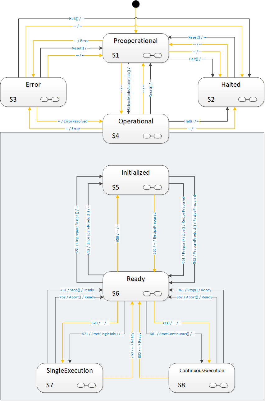
In the following state diagram, method-triggered transitions are again black with the method written as UML trigger; automatic transitions are orange with a possible event as UML effect introduced with a “/”.
To clarify the entire context, the other main states are also shown in Figure 24. For clarity, transitions from the top-level VisionStateMachine into states of the VisionAutomaticModeStateMachine are not shown in the diagram.
Interactions between external systems and the global “AutomaticMode” state machine are limited to few transitions in the model which we will see in detail in the description of methods and transitions. The most prominent points are obviously the Start-methods, typically used by a client to start operation of a vision system.
However, there is frequently a need to synchronize operations between the vision systems and external systems where the vision system remains conceptually in one of the states of the “AutomaticMode” state machine. The most obvious example is that of taking images of a part from various positions, either by moving the part relative to a camera system, handling it with a robot arm, or by moving the camera relative to the part, again possibly by a robot manipulator. This entire interaction would conceptually take place within SingleExecution state or ContinuousExecution state.
To enable all states in the “AutomaticMode” state machine to carry out such interactions, each is marked as a complex state by the  symbol, and has an optional SubStateMachine of the VisionStepModelStateMachineType.
8.3.2 Operation of the “AutomaticMode” state machine.
8.3.2.1 Introduction
The AutomaticMode state machine is entered from state Preoperational of the VisionStateMachineType either by an automatic operation or by the SelectModeAutomatic method.
A call to SelectModeAutomatic causes transition to state Initialized. Alternatively, the system can automatically transition into Initialized.
It is expected that within the states Initialized and Ready, the system can carry out management operations, with recipes and configurations. In order to carry out automatic evaluations, at least one recipe needs to be prepared in the system.
Recipe management is very system- and application-specific and correspondingly hard to generalize. Therefore, systems may exhibit different state transition behavior caused by recipe management methods, according to their capabilities. This is described in detail in Annex B.1 and the definition of the RecipeManagementType in chapter 7.5.
At some point, the system will be in Ready state. The simplest way will typically be a single call to AddRecipe and to PrepareRecipe to load and prepare a single recipe.
It is expected that in state Ready the system can at any time start an evaluation operation. This operation is denoted as a “job”. The “AutomaticMode” state machine defines two distinct methods of carrying out evaluation, namely “single job” operation and “continuous” operation.
Typical examples for SingleJob operation are the inspection of individual work pieces. Typical examples for Continuous operation are web inspection, package sorting, etc. The main differences between these two types of jobs are:
With a SingleJob, the client starting the job can reasonably expect it to end after an application-specific, but finite time; a Continuous job will typically not end on its own, so the notion of a timeout is meaningless.
Within a SingleJob, typically an AcquisitionDone event will be triggered at some point, informing the environment that all required data has been acquired so that the inspection part can leave the field of view of the camera, either by moving the part or the camera.
The image processing operation is accordingly started by one of two start methods, StartSingleJob or StartContinuous.
In single job as well as in continuous operation, the system can produce an arbitrary number of results, all of them partial with the exception of the last one. Whenever a partial or final result is available, the system shall trigger a ResultReady event with a result ID.
The result can then be retrieved by one of the GetResult method calls or directly from the ResultContent Component of the ResultReady event if it is included in the event Typically, the result will be available through a GetResult method call even if included with the ResultReady event, however the client cannot make assumptions about the result management of the vision system. This has to be treated in an application-specific way.
8.3.2.2 Single job operation
A call to the StartSingleJob method will cause a transition into state SingleExecution, where the system will typically acquire data and, once it has finished acquiring data, will fire an AcquisitionDone event. Note that there is no temporal relationship between the system returning to the Ready state and the completion of image acquisition or processing for the job triggered by a Start method. The system can already have left state SingleExecution to Ready, it can even accept another Start method call and carry out the next job, before the AcquisitionDone event for the previous job occurs, if the system is capable of handling several image acquisitions and/or image evaluations simultaneously.
From the point of view of the OPC UA client, the state machine is always carrying out one job only. However, there may be evaluation process of several jobs running in parallel on the system and may trigger AcquisitionDone events as well as ResultReady events.
Whenever the system is ready for the next StartSingleJob method, it will transition into the Ready state again.
8.3.2.3 Continuous operation
A call to the StartContinuous method will cause a transition into state ContinuousExecution, where the system will continuously acquire and process data.
This state models the behavior of systems like textile inspection systeme, package sorting machines, monitoring and surveillance systems, which do not expect start commands for individual work pieces but constantly acquire and process data.
The system may go back to the Ready state, automatically due to internal conditions, or by calling the Abort or Stop methods.
8.3.2.4 General remarks on Stop and Abort methods
The Stop and Abort methods offer two different means of finishing operation in the “Executing” states, with the intention that the system transitions to the Ready state.
Both can be considered intended interruptions of a running system, in contrast to an error or the complete stopping of operations by Reset and Halt methods.
The difference between the two methods is:
In response to an Abort method call, the system is expected to end running operation and transition to the Ready state as fast as possible, without regard to acquired or computed data.
In response to a Stop method call, the system is expected to end running operation and transition to the Ready state as soon as possible while retaining as much result data as possible. It is expected that results will become available for all images acquired before the Stop method was called.
These methods shall always be executable. If for some reason the vision system is not capable of carrying out this transition, the method shall fail with an appropriate status code, typically Bad_InternalError, and the state machine shall transition into the Error state.
For example, depending on the camera / sensor used, it may not be possible to interrupt the acquisition process arbitrarily from the outside.
8.3.2.5 Entering the “AutomaticMode” state machine
As described in Section 8.1.2.1 the VisionAutomaticMode SubStateMachine of the Operational state can be entered in two different ways:
From the Preoperational state of the parent state machine through an automatic transition or a transition triggered by the SelectModeAutomatic method into the Initialized state of the VisionAutomaticModeStateMachine . In these cases, the parent state machine transitions into the parent state Operational implicitly.
From the Error state of the parent state machine through an automatic transition into the Operational state of the parent state machine. In this case the server will decide based on the conditions in the vision system in which state of the VisionAutomaticModeStateMachine the system ends up.
Figure 25 shows these ways; for clarity, all other transitions have been left out. The transitions from the Preoperational state are shown as solid lines as they are actually modelled in the type definition. The transitions from the Error state are shown in dashed lines as they are not explicitly modelled but only “virtual” transitions decided by the server internally.
8.3.3 VisionAutomaticModeStateMachineType Overview
8.3.4 VisionAutomaticModeStateMachineType Definition
VisionAutomaticModeStateMachineType is formally defined in Table 96.
| Attribute | Value | ||||
| Includes all attributes specified for the FiniteStateMachineType | |||||
| BrowseName | VisionAutomaticModeStateMachineType | ||||
| IsAbstract | False | ||||
| References | NodeClass | BrowseName |
Data
Type | TypeDefinition | ModellingRule |
|---|---|---|---|---|---|
| Subtype of the FiniteStateMachineType defined in OPC 10000-5 Annex B.4.5 | |||||
| HasComponent | Object | Initialized | -- | StateType | |
| HasComponent | Object | Ready | -- | StateType | |
| HasComponent | Object | SingleExecution | -- | StateType | |
| HasComponent | Object | ContinuousExecution | -- | StateType | |
| HasComponent | Object | InitializedToReadyRecipe | -- | TransitionType | |
| HasComponent | Object | InitializedToReadyProduct | -- | TransitionType | |
| HasComponent | Object | InitializedToReadyAuto | -- | TransitionType | |
| HasComponent | Object | ReadyToInitializedRecipe | -- | TransitionType | |
| HasComponent | Object | ReadyToInitializedProduct | -- | TransitionType | |
| HasComponent | Object | ReadyToInitializedAuto | -- | TransitionType | |
| HasComponent | Object | ReadyToSingleExecution | -- | TransitionType | |
| HasComponent | Object | ReadyToSingleExecutionAuto | -- | TransitionType | |
| HasComponent | Object | ReadyToContinuousExecution | -- | TransitionType | |
| HasComponent | Object | ReadyToContinuousExecutionAuto | -- | TransitionType | |
| HasComponent | Object | SingleExecutionToReadyStop | -- | TransitionType | |
| HasComponent | Object | SingleExecutionToReadyAbort | -- | TransitionType | |
| HasComponent | Object | SingleExecutionToReadyAuto | -- | TransitionType | |
| HasComponent | Object | ContinuousExecutionToReadyStop | -- | TransitionType | |
| HasComponent | Object | ContinuousExecutionToReadyAbort | -- | TransitionType | |
| HasComponent | Object | ContinuousExecutionToReadyAuto | -- | TransitionType | |
| HasComponent | Method | Stop | -- | Mandatory | |
| HasComponent | Method | Abort | -- | Mandatory | |
| HasComponent | Method | StartSingleJob | -- | Mandatory | |
| HasComponent | Method | StartContinuous | -- | Mandatory | |
| HasComponent | Method | SimulationMode | -- | Optional | |
| HasComponent | Object | InitializedStepModel | -- | VisionStepModelStateMachineType | Optional |
| HasComponent | Object | ReadyStepModel | -- | VisionStepModelStateMachineType | Optional |
| HasComponent | Object | SingleExecutionStepModel | -- | VisionStepModelStateMachineType | Optional |
| HasComponent | Object | ContinuousExecutionStepModel | -- | VisionStepModelStateMachineType | Optional |
8.3.5 VisionAutomaticModeStateMachineType States
8.3.5.1 Introduction
Table 97 specifies the VisionAutomaticStateMachine’s state Objects. These state Objects are instances of the StateType defined in OPC 10000-5 – Annex B. Each state is assigned a unique StateNumber value.
See Table 98 for a brief description of the states. The states will be detailed in the following subsections.
Browse Name | References | Target BrowseName | Value | Target Type Definition | Notes |
| Initialized | HasProperty | StateNumber | 5 | PropertyType | -- |
| FromTransition | ReadyToInitializedRecipe | TransitionType | -- | ||
| FromTransition | ReadyToInitializedProduct | TransitionType | -- | ||
| FromTransition | ReadyToInitialzedAuto | TransitionType | -- | ||
| ToTransition | InitializedToReadyRecipe | TransitionType | -- | ||
| ToTransition | InitializedToReadyProduct | TransitionType | -- | ||
| ToTransition | InitializedToReadyAuto | TransitionType | -- | ||
| HasSubstate Machine | InitializedStepModel | VisionStepModel StateMachineType | -- | ||
| Ready | HasProperty | StateNumber | 6 | PropertyType | -- |
| FromTransition | InitializedToReadyRecipe | TransitionType | -- | ||
| FromTransition | InitializedToReadyProduct | TransitionType | -- | ||
| FromTransition | InitlializedToReadyAuto | TransitionType | -- | ||
| FromTransition | SingleExecutionToReadyStop | TransitionType | -- | ||
| FromTransition | SingleExecutionToReadyAbort | TransitionType | -- | ||
| FromTransition | SingleExecutionToReadyAuto | TransitionType | -- | ||
| FromTransition | ContinuousExecutionToReadyStop | TransitionType | -- | ||
| FromTransition | ContinousExecutionToReadyAbort | TransitionType | -- | ||
| FromTransition | ContinousExecutionToReadyAuto | TransitionType | -- | ||
| ToTransition | ReadyToInitializedRecipe | TransitionType | -- | ||
| ToTransition | ReadyToInitializedProduct | TransitionType | -- | ||
| ToTransition | ReadyToInitializedAuto | TransitionType | -- | ||
| ToTransition | ReadyToSingleExecution | TransitionType | -- | ||
| ToTransition | ReadyToSingleExecutionAuto | TransitionType | -- | ||
| ToTransition | ReadyToContinuousExecution | TransitionType | -- | ||
| ToTransition | ReadyToContinuousExecutionAuto | TransitionType | -- | ||
| HasSubstate Machine | ReadyStepModel | VisionStepModel StateMachineType | -- | ||
| Single Execution | HasProperty | StateNumber | 7 | PropertyType | -- |
| FromTransition | ReadyToSingleExecution | TransitionType | -- | ||
| FromTransition | ReadyToSingleExecutionAuto | TransitionType | -- | ||
| ToTransition | SingleExecutionToReadyStop | TransitionType | -- | ||
| ToTransition | SingleExecutionToReadyAbort | TransitionType | -- | ||
| ToTransition | SingleExecutionToReadyAuto | TransitionType | -- | ||
| HasSubstate Machine | SingleExecutionStepModel | VisionStepModel StateMachineType | -- | ||
| Continuous Execution | HasProperty | StateNumber | 8 | PropertyType | -- |
| FromTransition | ReadyToContinuousExecution | TransitionType | -- | ||
| FromTransition | ReadyToContinuousExecutionAuto | TransitionType | -- | ||
| ToTransition | ContinuousExecutionToReadyStop | TransitionType | -- | ||
| ToTransition | ContinousExecutionToReadyAbort | TransitionType | -- | ||
| ToTransition | ContinousExecutionToReadyAuto | TransitionType | -- | ||
| HasSubstate Machine | ContinuousExecutionStepModel | VisionStepModel StateMachineType | -- |
| StateName | Description |
| Initialized | This state indicated that the vision system is sufficiently initialized so that management operations like configuration and recipe management can be carried out through the server, if the optional management objects exist. |
| Ready | This state indicates that the vision system is capable of being started to carry out jobs, e.g. through Start methods called on the server. |
| SingleExecution | This state indicates that the vision system will acquire the data required for carrying out a single inspection or measuring job and will finish whatever operations are necessary to return to the Ready state to accept the next job. |
| ContinuousExecution | This state indicates that the vision system continually acquires and processes data, until it is stopped by internal or external reasons, e.g. calling the Stop or Abort methods on the server. |
8.3.5.2 Initialized State
In this state, the system is characterized by the following properties:
The system is able to perform management and operations.
Configurations can be managed by methods detailed in Section 7.2.
Recipes can be managed by methods detailed in Sections 7.5, 7.6, 7.7.
One or more recipes can be prepared by the PrepareRecipe method such that these are ready to be used in processing operations.
Results can be pulled from the internal result-store by the methods detailed in Section 7.10.
The system can be put into simulation mode (see Section 8.3.7.5).
This state will be the first state entered in the VisionAutomaticModeStateMachine when the superior VisionStateMachine enters the Operational state either by an automatic transition from Preoperational or by a SelectModeAutomatic method call.
If an error is dectected which suspends normal operation, the system will change to the Error state in the VisionStateMachine.
This state can be left in the following ways:
Into Ready state by a PrepareRecipe method call.
Into Preoperational state of the VisionStateMachine by a Reset method call.
Into Halted state of the VisionStateMachine by a Halt method call.
Into Error state of the VisionStateMachine by an internal error.
All method-triggered transitions can also occur automatically upon an internal decision of the system.
This state can be a composite state with an optional VisionStepModelStateMachineType SubStateMachine.
8.3.5.3 Ready State
In this state, the system is characterized by the following properties:
The vision system has prepared one or more recipes such that they can be used for processing immediately upon a StartSingleJob or StartContinuous method call (unless it is a system without any recipe management).
The vision system is ready to accept either a StartSingleJob or a StartContinuous method to begin image processing operation.
Recipes can be added and retrieved by methods detailed in Sections 7.5, 7.6, 7.7.
Which recipes are ready for use can be changed by calling the PrepareRecipe method depending on the recipe handling capabilities of the system.
Results can be pulled from the internal result-store by the methods detailed in Section 7.5.
The vision system can be put into simulation mode (see Section 8.3.7.5).
Depending on the recipe handling capabilities of the vision system, calling an AddRecipe or PrepareRecipe method in this state may cause the system to fall back into Initialized state, temporarily preventing it from accepting Start methods.
If an error is dectected which suspends normal operation, the system will transition to Error state in the VisionStateMachine.
This state can be left in the following ways:
Into the SingleExecution state by a StartSingleJob method call.
Into the ContinuousExecution state by a StartContinuous method call.
Into the Initialized state by an UnprepareRecipe method call.
Into the Preoperational state of the VisionStateMachine by a Reset method call.
Into the Halted state of the VisionStateMachine by a Halt method call.
Into the Error state of the VisionStateMachine by an internal error.
All method-triggered transitions can also occur automatically upon an internal decision of the system.
This state can be a composite state with an optional VisionStepModelStateMachineType SubStateMachine.
8.3.5.4 SingleExecution State
In this state, the system is characterized by the following properties:
The vision system has received a command to begin the execution of an individual job (measuring, inspection, identifying, …), e.g. by a call to the StartSingleJob method on the server.
The vision system collects sensor data (i.e. acquiring single or multiple images, possibly awaiting triggers, often in hardware).
If data acquisition is a “multi-stage-process” (interaction with other devices) this may be modelled with a VisionStepModelType SubStateMachine (all states allow for this, but this is the most typical application, therefore we emphasize it here).
The vision system may indicate to the client by an AcquisitionDone event that acquisition has been finished, e.g. as a signal that the part can be removed from the camera’s field of view, either by moving the part or he camera.
The vision system carries out the processing of the acquired data at least so far that the internal resources are available to transition into state Ready to accept the next start command.
Results can be pulled from the internal result-store by the methods detailed in Section 7.5 (depending on the capabilities of the system).
Note that the above description illustrates a typical behavior. The vision system is, however, in no way obliged to perform any particular operation – like image acquisition or processing – in this state. It can do completely different things or nothing at all before returning to Ready state. The point is rather that the difference between SingleExecution state and Ready state lies in the availability of the required resources for starting a job.
If an error is detected which suspends normal operation, the system will change to state Error in the VisionStateMachine.
This state can be left in the following ways:
into the Ready state by an automatic transition when the required resources are available. The system shall trigger a Ready event in this case. Note that this is in no way related to the vision system completing an image acquisition or evaluation and/or producing a result.
Into the Ready state by the methods Stop and Abort, see Section 8.3.2.4 for details.
Into the Preoperational state of the VisionStateMachine by a Reset method call.
Into the Halted state of the VisionStateMachine by a Halt method call.
Into the Error state of the VisionStateMachine by an internal error.
All method-triggered transitions can also occur automatically upon an internal decision of the system.
This state can be a composite state with an optional VisionStepModelStateMachineType SubStateMachine.
8.3.5.5 ContinuousExecution State
In this state, the system is characterized by the following properties:
The vision system has received a StartContinuous command to begin the execution of a continuous job
The vision system collects sensor data (i.e. acquiring single or multiple images, possibly awaiting triggers, often in hardware) and processes this in a continuously ongoing fashion.
Results can be pulled from the internal result-store by the methods detailed in Section 7.5 (depending on the capabilities of the system).
Note that the above description illustrates a typical behavior. The vision system is, however, in no way obliged to perform any particular operation – like image acquisition or processing – in this state. It can do completely different things or nothing at all before returning to Ready state. The point is rather that the difference between ContinuousExecution state and Ready state lies in the availability of the required resources for starting a job.
If an error is detected which suspends normal operation, the system will change to the Error state in the VisionStateMachine.
This state can be left in the following ways:
Into the Ready state by Stop and Abort method calls, see Section 8.3.2.4 for details.
Into the Preoperational state of the VisionStateMachineType by a Reset method call.
Into the Halted state of the VisionStateMachineType by a Halt method call.
Into the Error state of the VisionStateMachineType by an internal error.
All method-triggered transitions can also occur automatically upon an internal decision of the system.
This state can be a composite state with an optional VisionStepModelStateMachineType SubStateMachine.
8.3.6 VisionAutomaticModeStateMachineType Transitions
Transitions are instances of Objects of the TransitionType defined in OPC 10000-5 – Annex B which also includes the definitions of the ToState, FromState, HasCause, and HasEffect References used. Table 99 specifies the Transitions defined for the VisionStateMachineType. Each Transition is assigned a unique TransitionNumber.
| BrowseName | References | Target BrowseName | Value | Target TypeDefinition | Notes |
| InitializedToReadyRecipe | HasProperty | TransitionNumber | 561 | PropertyType | -- |
| FromState | Initialized | StateType | -- | ||
| ToState | Ready | StateType | -- | ||
| HasCause | PrepareRecipe | Method | -- | ||
| HasEffect | StateChangedEventType | -- | |||
| HasEffect | RecipePreparedEventType | -- | |||
| InitializedToReadyProduct | HasProperty | TransitionNumber | 562 | PropertyType | -- |
| FromState | Initialized | StateType | -- | ||
| ToState | Ready | StateType | -- | ||
| HasCause | PrepareProduct | Method | -- | ||
| HasEffect | StateChangedEventType | -- | |||
| HasEffect | RecipePreparedEventType | -- | |||
| InitializedToReadyAuto | HasProperty | TransitionNumber | 560 | PropertyType | -- |
| FromState | Initialized | StateType | -- | ||
| ToState | Ready | StateType | -- | ||
| HasEffect | StateChangedEventType | -- | |||
| ReadyToInitializedRecipe | HasProperty | TransitionNumber | 651 | PropertyType | -- |
| FromState | Ready | StateType | -- | ||
| ToState | Initialized | StateType | -- | ||
| HasCause | UnprepareRecipe | Method | -- | ||
| HasEffect | StateChangedEventType | -- | |||
| ReadyToInitializedProduct | HasProperty | TransitionNumber | 652 | PropertyType | -- |
| FromState | Ready | StateType | -- | ||
| ToState | Initialized | StateType | -- | ||
| HasCause | UnprepareProduct | Method | -- | ||
| HasEffect | StateChangedEventType | -- | |||
| ReadyToInitializedAuto | HasProperty | TransitionNumber | 650 | PropertyType | -- |
| FromState | Ready | StateType | -- | ||
| ToState | Initialized | StateType | -- | ||
| HasEffect | StateChangedEventType | -- | |||
| ReadyToSingleExecution | HasProperty | TransitionNumber | 671 | PropertyType | -- |
| FromState | Ready | StateType | -- | ||
| ToState | SingleExecution | StateType | -- | ||
| HasCause | StartSingleJob | Method | -- | ||
| HasEffect | StateChangedEventType | -- | |||
| HasEffect | JobStartedEventType | -- | |||
| ReadyToSingleExecutionAuto | HasProperty | TransitionNumber | 670 | PropertyType | -- |
| FromState | Ready | StateType | -- | ||
| ToState | SingleExecution | StateType | -- | ||
| HasEffect | StateChangedEventType | -- | |||
| HasEffect | JobStartedEventType | -- | |||
| ReadyToContinuousExecution | HasProperty | TransitionNumber | 681 | PropertyType | -- |
| FromState | Ready | StateType | -- | ||
| ToState | ContinuousExecution | StateType | -- | ||
| HasCause | StartContinuous | Method | -- | ||
| HasEffect | StateChangedEventType | -- | |||
| HasEffect | JobStartedEventType | -- | |||
| ReadyToContinuousExecutionAuto | HasProperty | TransitionNumber | 680 | PropertyType | -- |
| FromState | Ready | StateType | -- | ||
| ToState | ContinuousExecution | StateType | -- | ||
| HasEffect | StateChangedEventType | -- | |||
| HasEffect | JobStartedEventType | -- | |||
| SingleExecutionToReadyAuto | HasProperty | TransitionNumber | 760 | PropertyType | -- |
| FromState | SingleExecution | StateType | -- | ||
| ToState | Ready | StateType | -- | ||
| HasEffect | StateChangedEventType | -- | |||
| HasEffect | ReadyEventType | -- | |||
| SingleExecutionToReadyStop | HasProperty | TransitionNumber | 761 | PropertyType | |
| FromState | SingleExecution | StateType | -- | ||
| ToState | Ready | StateType | -- | ||
| HasCause | Stop | Method | -- | ||
| HasEffect | StateChangedEventType | -- | |||
| HasEffect | ReadyEventType | -- | |||
| SingleExecutionToReadyAbort | HasProperty | TransitionNumber | 762 | PropertyType | -- |
| FromState | SingleExecution | StateType | -- | ||
| ToState | Ready | StateType | -- | ||
| HasCause | Abort | Method | -- | ||
| HasEffect | StateChangedEventType | -- | |||
| HasEffect | ReadyEventType | -- | |||
| ContinuousExecutionToReadyAuto | HasProperty | TransitionNumber | 860 | PropertyType | -- |
| FromState | ContinuousExecution | StateType | -- | ||
| ToState | Ready | StateType | -- | ||
| HasEffect | StateChangedEventType | -- | |||
| HasEffect | ReadyEventType | -- | |||
| ContinuousExecutionToReadyStop | HasProperty | TransitionNumber | 861 | PropertyType | -- |
| FromState | ContinuousExecution | StateType | -- | ||
| ToState | Ready | StateType | -- | ||
| HasCause | Stop | Method | -- | ||
| HasEffect | StateChangedEventType | -- | |||
| HasEffect | ReadyEventType | -- | |||
| ContinuousExecutionToReadyAbort | HasProperty | TransitionNumber | 862 | PropertyType | -- |
| FromState | ContinuousExecution | StateType | -- | ||
| ToState | Ready | StateType | -- | ||
| HasCause | Abort | Method | -- | ||
| HasEffect | StateChangedEventType | -- | |||
| HasEffect | ReadyEventType | -- |
8.3.7 VisionAutomaticModeStateMachineType Methods
8.3.7.1 StartSingleJob method
Calling this method on the server is used to start a single execution type job in the vision system which will be reflected by transition from the Ready state to the SingleExecution state.
Signature
StartSingleJob ([in] MeasIdDataType measId,[in] PartIdDataType partId,[in] RecipeIdExternalDataType recipeId[in] ProductIdDataType productId[in] BaseDataType[] parameters[out] JobIdDataType jobId[out] Int32 error);| Argument | Description |
| measId | Identifies the measuring or inspection run from the point of view of the client. May be empty. |
| partId | Identifies the part to be measured or inspected from the point of view of the client. The partId may be identical on different measIDs, e.g. for repeat measurements in capability tests. May be empty. |
| recipeId | If not empty, it must be the ExternalId of a prepared recipe which is to be used by this job. |
| productId | It not empty, it must be the ProductId of a product for which a recipe has been prepared which is to be used by this job. |
| parameters | List of parameters for this particular execution of the recipe; number and type of the parameters are recipe-specific, so the client may need to re-browse the method signature after a change in recipe preparation. |
| jobId | A system-wide unique identification of the job. This argument must be returned. |
| error | 0 – OK Values > 0 are reserved for errors defined by this and future standards. Values < 0 shall be used for application-specific errors. |
| Attribute | Value | ||||
| BrowseName | StartSingleJob | ||||
| References | NodeClass | BrowseName | DataType | TypeDefinition | ModellingRule |
|---|---|---|---|---|---|
| HasProperty | Variable | InputArguments | Argument[] | PropertyType | Mandatory |
| HasProperty | Variable | OutputArguments | Argument[] | PropertyType | Mandatory |
It is expected that clients work either recipe-based or product-based, i.e. that a client gives either the RecipeId argument or the ProductId argument. Recipe and product management being the province of the vision system, it is implementation defined how the vision system reacts to none or both be given
Typical possibilities are that a system without recipe management or with only a single prepared recipe can use this recipe to execute a job and accept both parameters to be empty, whereas a system with multiple prepared recipes would probably consider it an error if both are empty and decide based on internal rules which takes precedence if both are given.
Results are to be marked with as many of the identification values as possible to allow for unique identification and flexible filtering, i.e., it is expected that the server uses all meta data elements provided by the client and supported by the server profile to mark the results, filter the results, and fill the ResultReady event.
The jobId is mandatory to be returned and to be included in results.
Restarting with the same measId can lead to identical or different jobIds, depending on the application. It is therefore not reliably possible to use multiple calls with the same measId to query for jobIds.
The parameters argument is intended for filling free parameters of a recipe with concrete values for the given job. Its structure is therefore dependent on the recipe used. The server will have to instantiate this method with an application-specific parameter structure before entering the Ready state. The server may re-instantiate this method with a different parameter structure after preparing a different recipe. In the case of several recipes being in prepared state at the same time, this structure is expected to be the superset of parameters required by the prepared recipes. The client will have to browse for the actual argument structure of the method at least once before calling a Start method (in the case of a system without recipe management) and application-specific potentially after each call to PrepareRecipe.
8.3.7.2 StartContinuous method
Calling this method on the server is used to start a continuous execution type job in the vision system which will be reflected by transition from the Ready state to the ContinuousExecution state. It has the same signature and semantics as method StartSingleJob described in Section 8.3.7.1.
| Attribute | Value | ||||
| BrowseName | StartContinuous | ||||
| References | NodeClass | BrowseName | DataType | TypeDefinition | ModellingRule |
|---|---|---|---|---|---|
| HasProperty | Variable | InputArguments | Argument[] | PropertyType | Mandatory |
| HasProperty | Variable | OutputArguments | Argument[] | PropertyType | Mandatory |
8.3.7.3 Abort method
In response to an Abort call on the server, the vision system is expected to end running operation and transition to the Ready state as fast as possible, without regard to acquired or computed data.
See the general remarks on Stop and Abort methods in Section 8.3.2.4 for further information on the behavior.
Signature
Abort ([in] Int32 cause[in] String causeDescription[out] Int32 error);| Argument | Description |
| cause | Implementation-specific number denoting the reason for the Abort command. |
| causeDescription | Text for said reason, e.g. for logging purposes. May be empty. |
| error | 0 – OK Values > 0 are reserved for errors defined by this and future standards. Values < 0 shall be used for application-specific errors. |
| Attribute | Value | ||||
| BrowseName | Abort | ||||
| References | NodeClass | BrowseName | DataType | TypeDefinition | ModellingRule |
|---|---|---|---|---|---|
| HasProperty | Variable | InputArguments | Argument[] | PropertyType | Mandatory |
| HasProperty | Variable | OutputArguments | Argument[] | PropertyType | Mandatory |
The cause argument given to the method can only be interpreted by the underlying vision system It can be used, for example, for logging purposes. It is expected that a value of 0 will be considered an “unspecified reason”.
8.3.7.4 Stop method
In response to a Stop method call on the server, the vision system is expected to end running operation and transition to state Ready as soon as possible while retaining as much result data as possible.
See the general remarks on Stop and Abort in 8.3.2.4 for further information on the behavior.
Signature
Stop ([in] Int32 cause[in] String causeDescription[out] Int32 error);
| Argument | Description |
| cause | Implementation-specific number denoting the reason for the Stop command. |
| causeDescription | Text for said reason, e.g. for logging purposes. May be empty. |
| error | 0 – OK Values > 0 are reserved for errors defined by this and future standards. Values < 0 shall be used for application-specific errors. |
| Attribute | Value | ||||
| BrowseName | Stop | ||||
| References | NodeClass | BrowseName | DataType | TypeDefinition | ModellingRule |
|---|---|---|---|---|---|
| HasProperty | Variable | InputArguments | Argument[] | PropertyType | Mandatory |
| HasProperty | Variable | OutputArguments | Argument[] | PropertyType | Mandatory |
The cause argument given to the method can only be interpreted by the underlying vision system It can be used, for example, for logging purposes. It is expected that a value of 0 will be considered an “unspecified reason”.
8.3.7.5 SimulationMode method
This method puts the system into a system-specific special mode of operation. It is expected that this mode does one or all of the following things:
Simulate hardware (for tests on notebook)
Produce simulated results (for tests within the line)
Simulate parts of a recipe
It is mandatory that each result produced by the system when simulation mode is on must be marked with a simulation flag.
Signature
SimulationMode ([in] Boolean activate[in] Int32 cause[in] String causeDescription[out] Int32 error);
| Argument | Description |
| activate | Switch simulation on (true) or off (false) |
| cause | Implementation specific number which the server can use, e.g. to control the simulation in a specific way |
| causeDescription | String describing the reason for the call, for logging purposes May be empty. |
| error | 0 – OK Values > 0 are reserved for errors defined by this and future standards. Values < 0 shall be used for application-specific errors. |
| Attribute | Value | ||||
| BrowseName | SimulationMode | ||||
| References | NodeClass | BrowseName | DataType | TypeDefinition | ModellingRule |
|---|---|---|---|---|---|
| HasProperty | Variable | InputArguments | Argument[] | PropertyType | Mandatory |
| HasProperty | Variable | OutputArguments | Argument[] | PropertyType | Mandatory |
8.3.8 VisionAutomaticModeStateMachineType Events
8.3.8.1 RecipePreparedEventType
RecipePreparedEventType is an EventType subtype of BaseEventType, defined in OPC 10000-5. This event shall be triggered by the server when the preparation of a recipe is completed on the vision system. Figure 27 defines the structure. It is formally defined in Table 109.
Typically, if the RecipeManagementType object is carried out by the server in a synchronous manner, this event will be triggered before the method returns, but there is no specified temporal relationship between the call to the PrepareRecipe method and the triggering of the event (except for the obvious that the event cannot occur before the call).
The same holds for the PrepareProduct method of the RecipeManagementType object which, in effect, also prepares a recipe.
An important special case, described in Section B.1.2.3, is local editing of an already prepared recipe. Since after local editing has finished, the recipe is a different one than before, effectively a new recipe has been prepared. Therefore, local editing of a prepared recipe shall generate a RecipePrepared event.
The RecipePrepared event transports the identification of the prepared recipe. If the event was caused by a PrepareProduct method call, it also transports the ProductId, otherwise the ProductId shall be empty.
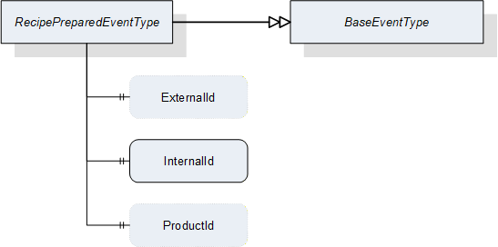
| Attribute | Value | ||||
| BrowseName | RecipePreparedEventType | ||||
| IsAbstract | False | ||||
| References | NodeClass | BrowseName | DataType | TypeDefinition | ModellingRule |
|---|---|---|---|---|---|
| Subtype of the BaseEventType defined in OPC 10000-5 | |||||
| HasProperty | Variable | ExternalId | RecipeIdExternalDataType | PropertyType | Optional |
| HasProperty | Variable | InternalId | RecipeIdInternalDataType | PropertyType | Mandatory |
| HasProperty | Variable | ProductId | ProductIdDataType | PropertyType | Optional |
8.3.8.2 JobStartedEventType
JobStartedEventType is an EventType subtype of BaseEventType, defined in OPC 10000-5. This event is to be triggered by the server when the state machine transitions from the Ready state to the SingleExecution or ContinuousExecution state. Figure 28 defines the structure. It is formally defined in Table 110.
It indicates to the client that the vision system has started the execution of a job, regardless whether the transition occurred due to a call to the StartSingleJob or StartContinuous method or automatically due, e.g. for a fieldbus start signal.
The event transports the jobId created upon the transition from state Ready to state SingleExecution or ContinuousExecution. This enables clients to maintain a time-sequential log of jobs, regardless whether this particular client started the job or whether the job was started by an OPC UA method call at all.
In the case of multiple running state machines in the same server, the client can use the Source property inherited from BaseEventType to identify the state machine instance the event originated from.

| Attribute | Value | ||||
| BrowseName | JobStartedEventType | ||||
| IsAbstract | False | ||||
| References | NodeClass | BrowseName | DataType | TypeDefinition | ModellingRule |
|---|---|---|---|---|---|
| Subtype of the BaseEventType defined in OPC 10000-5 | |||||
| HasProperty | Variable | JobId | JobIdDataType | PropertyType | Mandatory |
8.3.8.3 ReadyEventType
ReadyEventType is an EventType subtype of BaseEventType, defined in OPC 10000-5. This event is to be triggered by the server when the state machine transitions to the Ready state from one of the “Execution” states, i.e. SingleExecution or ContinuousExecution. Figure 29 defines the structure. It is formally defined in Table 111.
It indicates to the client that the vision system has the necessary resources available for executing the next job. The client still has to make sure that the state machine is actually in the Ready state before calling the StartSingleJob or StartContinuous method as the vision system may fall out of the Ready state due to internal reasons or other method calls
The event transports the jobId created upon the transition from state Ready to state SingleExecution or ContinuousExecution. Together with the JobStarted event this enables clients to maintain a time-sequential log of state changes for each job.
In the case of multiple running state machines in the same server, the client can use the Source property inherited from BaseEventType to identify the state machine instance the event originated from.
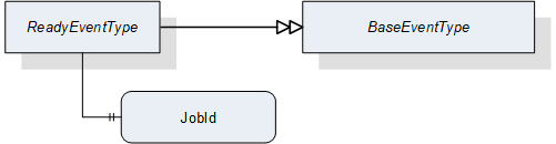
| Attribute | Value | ||||
| BrowseName | ReadyEventType | ||||
| IsAbstract | False | ||||
| References | NodeClass | BrowseName | DataType | TypeDefinition | ModellingRule |
|---|---|---|---|---|---|
| Subtype of the BaseEventType defined in OPC 10000-5 | |||||
| HasProperty | Variable | JobId | JobIdDataType | PropertyType | Mandatory |
8.3.8.4 ResultReadyEventType
ResultReadyEvent is an EventType subtype of BaseEventType, defined in OPC 10000-5. This event is to be triggered by the server when the vision system has a complete or partial result available for the client. Figure 30 defines the structure. It is formally defined in Table 112.
To enable access to a result, several properties of the result, which are generated by the system, are supplied. These properties can be used to query the results in the ResultManagement object. A sufficiently small result can also be provided in the ResultContent component of the event.
The ResultReadyEvent is not shown explicitly in the state machine as it is not connected to a state transition.
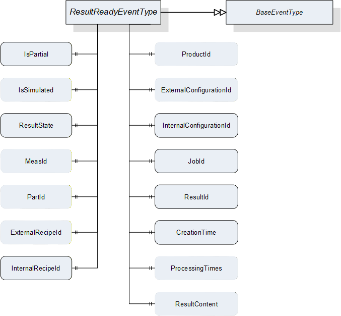
| Attribute | Value | ||||
| BrowseName | ResultReadyEventType | ||||
| IsAbstract | False | ||||
| References | NodeClass | BrowseName | DataType | TypeDefinition | ModellingRule |
|---|---|---|---|---|---|
| Subtype of the BaseEventType defined in OPC 10000-5 | |||||
| HasProperty | Variable | IsPartial | Boolean | PropertyType | Mandatory |
| HasProperty | Variable | IsSimulated | Boolean | PropertyType | Optional |
| HasProperty | Variable | ResultState | ResultStateDataType | PropertyType | Mandatory |
| HasProperty | Variable | MeasId | MeasIdDataType | PropertyType | Optional |
| HasProperty | Variable | PartId | PartIdDataType | PropertyType | Optional |
| HasProperty | Variable | ExternalRecipeId | RecipeIdExternalDataType | PropertyType | Optional |
| HasProperty | Variable | InternalRecipeId | RecipeIdInternalDataType | PropertyType | Mandatory |
| HasProperty | Variable | ProductId | ProductIdDataType | PropertyType | Optional |
| HasProperty | Variable | ExternalConfigurationId | ConfigurationIdDataType | PropertyType | Optional |
| HasProperty | Variable | InternalConfigurationId | ConfigurationIdDataType | PropertyType | Mandatory |
| HasProperty | Variable | JobId | JobIdDataType | PropertyType | Mandatory |
| HasProperty | Variable | ResultId | ResultIdDataType | PropertyType | Mandatory |
| HasProperty | Variable | CreationTime | UtcTime | PropertyType | Mandatory |
| HasProperty | Variable | ProcessingTimes | ProcessingTimesDataType | PropertyType | Optional |
| HasProperty | Variable | ResultContent | BaseDataType[] | PropertyType | Optional |
IsPartial
Indicates whether the result is the partial result of a total result.
IsSimulated
Indicates whether the system was in simulation mode when the job generating this result was created.
ResultState
Indicates at what processing state this result was generated.
MeasId, PartId, ExternalRecipeId, InternalRecipeId, ProductId, ExternalConfigurationId, InternalConfigurationId, JobId, ResultId
If the information is somehow linked to one of the (vision system) objects referenced by these Ids, these properties can transport this reference. In particular:
MeasId: This identifier is given by the client when starting a single or continuous execution and transmitted to the vision system. It is used to identify the respective result data generated for this job. Although the system-wide unique JobId would be sufficient to identify the job which the result belongs to, this makes for easier filtering on the part of the client without keeping track of JobIds.
PartId: A PartId is given by the client when starting the job; although the system-wide unique JobId would be sufficient to identify the job which the result belongs to, this makes for easier filtering on the part of the client without keeping track of JobIds.
ExternalRecipeId:
External Id of the recipe in use which produced the result. The ExternalId is only managed by the environment. This will typically be derived from the arguments of the Start method call which caused the result to be created.
InternalRecipeId:
Internal Id of the recipe in use which produced the result. This Id is system-wide unique and it is assigned by the vision system. This will typically be derived from the arguments of the Start method call which caused the result to be created.
ProductId: Id of the product selected to produce the result. This will typically be derived from the arguments of the Start method call which caused the result to be created.
ExternalConfigurationId: External Id of the configuration in effect in the system when the result was produced.
InternalConfigurationId: Internal Id of the configuration in effect in the system when the result was produced.
JobId:
The Id of the job, created by the transition from state Ready to state SingleExecution or to state ContinuousExecution which produced the result.
ResultId: vision-system-wide unique Id, which is assigned by the system. This Id can be used for fetching exactly this result using the methods detailed in Section 7.10.2.
CreationTime
CreationTime indicates the time when the result was created.
ProcessingTimes
Collection of different processing times that were needed to create the result.
ResultContent
Abstract data type to be subtyped from to hold result data created by the selected recipe.
8.3.8.5 AcquisitionDoneEventType
AcquisitionDoneEventType is an EventType subtype of BaseEventType, defined in OPC 10000-5. This event is to be triggered by the server. when the vision system finishes a data acquisition process for a job. Figure 31 shows the structure of the event. It is formally defined in Table 113.
It is not shown explicitly in the state machine diagram as it is not directly connected to a transition.
It indicates to the client that data acquisition for the specified job has finished. In many machines, this will be a signal that the work piece or camera can be moved. Triggering this event during a single or continuous execution is application-specific and not mandatory.
The event provides the JobId created upon the transition from the Ready state to the SingleExecution or ContinuousExecution state. This enables the client to maintain a time-sequential log of state changes for each job and also to match the event to the corresponding start signal.
In the case of multiple running state machines in the same server, the client can use the Source property inherited from BaseEventType to identify the state machine instance the event originated from.
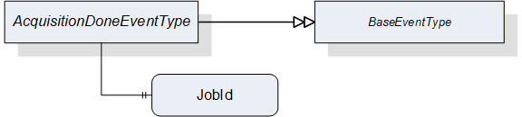
| Attribute | Value | ||||
| BrowseName | AcquisitionDoneEventType | ||||
| IsAbstract | False | ||||
| References | NodeClass | BrowseName | DataType | TypeDefinition | ModellingRule |
|---|---|---|---|---|---|
| Subtype of the BaseEventType defined in OPC 10000-5 | |||||
| HasProperty | Variable | JobId | JobIdDataType | PropertyType | Mandatory |
JobId
The Id of the job for which the event was triggered. The JobId is created by the transition from state Ready to state Acquiring.
8.3.9 Adding an operation mode
If a vendor wants to add a mode of operation, the following steps are required:
Define a SubType of FiniteStateMachineType describing the behavior of this operation mode, designated here as VendorModeStateMachineType. This SubType shall not have an InitialState to allow for selective activation of operation modes.
Define a SubType of VisionStateMachineType which
binds an instance of VendorModeStateMachineType as SubStateMachine to the Operational state of this SubType.
defines a SelectModeVendor method to trigger a transition into a desired starting state of this SubStateMachine.
binds the SelectModeVendor method as additional HasCause to the method-triggered transition from the Preoperational state to the Operational state, i.e., T141 in Table 84 (according to OPC 10000-5 B.4.18, adding causes to a transition is allowed, not however to introduce a new transition, so the existing transition ).
contains direct transitions from the Preoperational state into the desired starting state of the VendorModeStateMachine, typically an automatic one and one triggered by SelectModeVendor (again this is allowed by OPC 10000-5, B.4.18).
Take care that automatic transitions into the Operational state lead into states of the VendorModeStateMachine in a suitable way, especially for transitions from the Error state to facilitate the error handling described in Section 8.2.2.4.
The designation elements ModeStateMachineType and SelectMode shall be used as shown above. The Vendor part of the designations can be freely chosen.
8.4 VisionStepModelStateMachineType
8.4.1 Operation of the VisionStepModelStateMachine
Vision systems frequently require interaction with external systems during image acquisition. For example, it may be required to capture images in several different positions, i.e., moving the part between image capturing operations. In that case, the vision system will signal to the PLC when it has captured an image, so that the part may be safely moved, and the PLC will in turn signal to the vision system when the part is in the next position to capture the next image.
To enable the states of the VisionAutomaticModeStateMachineType to do such interaction, each is a complex state with an optional SubStateMachine of the VisionStepModelStateMachineType.
Figure 32 shows the entire SubStateMachine diagram.
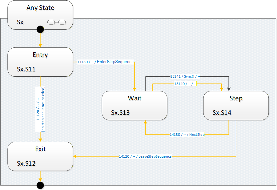
8.4.1.1 Entering the step model SubStateMachine
It is supposed that a SubStateMachine is entered automatically if it is present in the superior state. Since the Entry state is of InitialStateType it will be entered automatically.
Upon entering the SubStateMachine there is a check in the Entry state whether there is a step-sequence to execute. This is application-dependent and may depend on the situation (e.g. on the currently active recipe) and the way of determining this is application-specific.
8.4.1.2 Executing a step sequence
If in the Entry state the system decides that there is a step sequence to be executed, the SubStateMachine informs the client about this by firing an EnterStepSequence event. It then enters the Wait state to wait for a synchronization event.
The synchronization can occur by a Sync method call from an OPC UA client, typically the control system. The synchronization can also occur internally, typically due to communication events on other interfaces, e.g. a digital trigger.
The system then enters the Step state, where it does the actual work required in this state of the step model and decides whether there are any steps left in the step sequence. This is application-specific, as is the original decision to execute a step sequence at all.
The system indicates the need for another step-sequence cycle by firing a NextStep event and re-enters the Wait state. In this manner, an arbitrary and dynamic number of steps can be executed. It is not necessary to predefine the number of steps.
To use the common example of image acquisition: There may be one image acquisition in each Step state, but it is also possible that the step sequence is used only for mechanical synchronization and all acquisition is done in the Exit state.
8.4.1.3 Completing the SubStateMachine
If no step-sequence is to be executed at all, the system will transition into the Exit state directly from the Entry state and perform the actual task of the superior state. After the task is finished, the superior state will transition to whatever is its target state, thus de-activating the SubStateMachine.
When a step sequence is being executed and the system decides in the Step state that there are no more steps to execute in the step sequence, it fires a LeaveStepSequence event, transitions to the Exit state and proceeds as in the case without a step sequence.
How the work of the superior state and of the steps of the sequence is distributed between the states of the step model is application-specific.
8.4.1.4 Leaving the superior state
The superior state of a currently active VisionStepModelStateMachine is some state in the VisionStateMachineType or the VisionAutomaticModeStateMachineType.
Each of these states can be left due to internal causes (like error conditions) or external causes (like the Stop, Abort, Halt, Reset method calls). In that case, the SubStateMachine becomes inactive and will be in state Bad_StateNotActive, as explained in Section 8.1.2.
How and when these transitions take place is at the discretion of the vision system underlying the OPC UA server. In particular, the vision system can disable the Executable flag on each of these methods when the current operation does not allow for, e.g. an Abort command to be carried out.
8.4.2 VisionStepModelStateMachineType Overview
This ObjectType is a subtype of FiniteStateMachineType and it is used to represent interactions of the vision system with external components/systems for synchronization purposes. It is formally defined in Table 114.
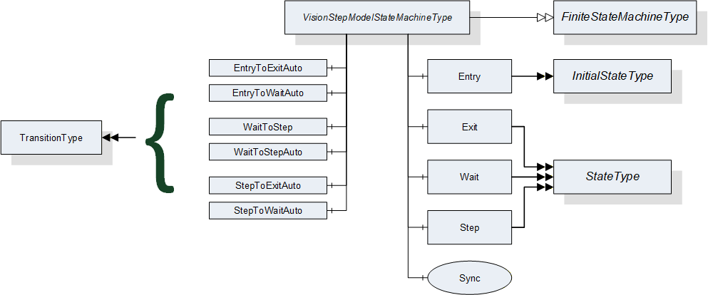
8.4.3 VisionStepModelStateMachineType Definition
VisionStepModelStateMachineType is formally defined in Table 114.
| Attribute | Value | ||||
| Includes all attributes specified for the FiniteStateMachineType | |||||
| BrowseName | VisionStepModelStateMachineType | ||||
| IsAbstract | False | ||||
| References | NodeClass | BrowseName | DataType | TypeDefinition | ModellingRule |
|---|---|---|---|---|---|
| Subtype of the FiniteStateMachineType defined in OPC 10000-5 Annex B.4.5 | |||||
| HasComponent | Object | Entry | -- | InitialStateType | -- |
| HasComponent | Object | Exit | -- | StateType | -- |
| HasComponent | Object | Wait | -- | StateType | -- |
| HasComponent | Object | Step | -- | StateType | -- |
| HasComponent | Object | EntryToExitAuto | -- | TransitionType | -- |
| HasComponent | Object | EntryToWaitAuto | -- | TransitionType | -- |
| HasComponent | Object | WaitToStep | -- | TransitionType | -- |
| HasComponent | Object | WaitToStepAuto | -- | TransitionType | -- |
| HasComponent | Object | StepToExitAuto | -- | TransitionType | -- |
| HasComponent | Object | StepToWaitAuto | -- | TransitionType | -- |
| HasComponent | Method | Sync | -- | -- | Mandatory |
8.4.4 VisionStepModelStateMachineType States
Table 115 lists the states of VisionStepModelStateMachineType. See Table 116 for a brief description of the states. These will be detailed in the following subsections.
| BrowseName | References | Target BrowseName | Value | Target TypeDefinition | Notes |
| Entry | HasProperty | StateNumber | 11 | PropertyType | -- |
| ToTransition | EntryToExitAuto | TransitionType | -- | ||
| ToTransition | EntryToWaitAuto | TransitionType | -- | ||
| Exit | HasProperty | StateNumber | 12 | PropertyType | -- |
| FromTransition | EntryToExitAuto | TransitionType | -- | ||
| FromTransition | StepToExitAuto | TransitionType | -- | ||
| Wait | HasProperty | StateNumber | 13 | PropertyType | -- |
| FromTransition | EntryToWaitAuto | TransitionType | -- | ||
| FromTransition | StepToWaitAuto | TransitionType | -- | ||
| ToTransition | WaitToStep | TransitionType | -- | ||
| ToTransition | WaitToStepAuto | TransitionType | -- | ||
| Step | HasProperty | StateNumber | 14 | PropertyType | -- |
| FromTransition | WaitToStep | TransitionType | -- | ||
| FromTransition | WaitToStepAuto | TransitionType | -- | ||
| ToTransition | StepToExitAuto | TransitionType | -- | ||
| ToTransition | StepToWaitAuto | TransitionType | -- |
| StateName | Description |
| Entry | If a superior state has a step model SubStateMachine, this state will be entered automatically. In this state, the step model SubStateMachine decides whether a step model execution is required or not. This decision may depend on the current recipe or other factors. |
| Exit | In this state, the SubStateMachine signals to the superior state that its work is finished so that the superior state can be completed and transition to its target state. The superior state may also be left at any time due to other reasons regardless of the current state of the step model. |
| Wait | In this state, the system waits for a synchronization event. This may be a call to the Sync method or other internal or external factor, e.g. communication via a different interface. |
| Step | In this state, the system carries out the work for the current step, then decides based on the current situation whether more steps are required, in which case the state machine transitions back into state Wait, or not, in which case the state machine transitions to the Exit state. |
8.4.5 VisionStepModelStateMachineType Transitions
Table 117 lists the transitions of VisionStepModelStateMachineType.
| BrowseName | References | Target BrowseName | Value | Target TypeDefinition | Notes |
| EntryToExitAuto | HasProperty | TransitionNumber | 11120 | PropertyType | -- |
| FromState | Entry | StateType | -- | ||
| ToState | Exit | StateType | -- | ||
| HasEffect | StateChangedEventType | -- | |||
| EntryToWaitAuto | HasProperty | TransitionNumber | 11130 | PropertyType | -- |
| FromState | Entry | StateType | -- | ||
| ToState | Wait | StateType | -- | ||
| HasEffect | EnterStepSequenceEventType | -- | |||
| HasEffect | StateChangedEventType | -- | |||
| WaitToStep | HasProperty | TransitionNumber | 13141 | PropertyType | -- |
| FromState | Wait | StateType | -- | ||
| ToState | Step | StateType | -- | ||
| HasCause | Sync | Method | -- | ||
| HasEffect | StateChangedEventType | -- | |||
| WaitToStepAuto | HasProperty | TransitionNumber | 13140 | PropertyType | -- |
| FromState | Wait | StateType | -- | ||
| ToState | Step | StateType | -- | ||
| HasEffect | StateChangedEventType | -- | |||
| StepToExitAuto | HasProperty | TransitionNumber | 14120 | PropertyType | -- |
| FromState | Step | StateType | -- | ||
| ToState | Exit | StateType | -- | ||
| HasEffect | LeaveStepSequenceEventType | -- | |||
| HasEffect | StateChangedEventType | -- | |||
| StepToWaitAuto | HasProperty | TransitionNumber | 14130 | PropertyType | -- |
| FromState | Step | StateType | -- | ||
| ToState | Wait | StateType | -- | ||
| HasEffect | NextStepEventType | -- | |||
| HasEffect | StateChangedEventType | -- |
8.4.6 VisionStepModelStateMachineType Methods
8.4.6.1 Sync method
This method can be called to cause a transition from the Wait state in the step model to the ExecuteStep state.
Signature
Sync ([in] Int32 cause[in] String causeDescription[out] Int32 error);| Argument | Description |
| cause | Implementation-specific number denoting circumstances of the command |
| causeDescription | Description of the circumstances, e.g. for logging purposes. May be empty. |
| error | 0 – OK Values > 0 are reserved for errors defined by this and future standards. Values < 0 shall be used for application-specific errors. |
| Attribute | Value | ||||
| BrowseName | Sync | ||||
| References | NodeClass | BrowseName | DataType | TypeDefinition | ModellingRule |
|---|---|---|---|---|---|
| HasProperty | Variable | InputArguments | Argument[] | PropertyType | Mandatory |
| HasProperty | Variable | OutputArguments | Argument[] | PropertyType | Mandatory |
The cause argument given to the method can only be interpreted by the underlying vision system It can be used, for example, for ending the step model prematurely.
8.4.7 VisionStepModelStateMachine Events
8.4.7.1 EnterStepSequenceEventType
EnterStepSequenceEventType is an EventType subtype of BaseEventType, defined in OPC 10000-5. This event is to be triggered by the server when in the Entry state the decision is taken that under the current circumstances (superior state, recipe etc.) a step sequence is to be executed and the transition into the first Wait state is initiated. The structure is defined in Figure 34. It is formally defined in Table 120.
Event properties
Steps: number of steps to expect. If the number of steps is not known, this should be -1. Even if this is a positive value, the client should not rely on it because circumstances occurring during execution of the step model may change the number of steps required, for example a call to the Sync method with a particular mode argument.
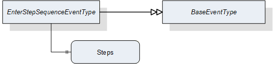
| Attribute | Value | ||||
| BrowseName | EnterStepSequenceEventType | ||||
| IsAbstract | False | ||||
| References | NodeClass | BrowseName | DataType | TypeDefinition | ModellingRule |
|---|---|---|---|---|---|
| Subtype of the BaseEventType defined in OPC 10000-5 | |||||
| HasProperty | Variable | Steps | Int32 | PropertyType | Mandatory |
8.4.7.2 NextStepEventType
NextStepEventType is an EventType subtype of BaseEventType, defined in OPC 10000-5. This event is to be triggered by the server when in the Step state the decision is reached that under the current circumstances (superior state, recipe, number of steps already taken, parameter of Sync method) another step has to be taken and the state machine must translate to the Wait state. It is formally defined in Table 121
Event properties
State NodeId
Running number of the step
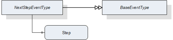
| Attribute | Value | ||||
| BrowseName | NextStepEventType | ||||
| IsAbstract | False | ||||
| References | NodeClass | BrowseName | DataType | TypeDefinition | ModellingRule |
|---|---|---|---|---|---|
| Subtype of the BaseEventType defined in OPC 10000-5 | |||||
| HasProperty | Variable | Step | Int32 | PropertyType | Mandatory |
8.4.7.3 LeaveStepSequenceEventType
LeaveStepSequenceEventType is an EventType subtype of BaseEventType, defined in OPC 10000-5, this event is to be triggered by the server when in the Step state the decision is reached that under the current circumstances (superior state, recipe, number of steps already taken, parameter of Sync method) no further steps have to be taken and the transition into the Exit state is initiated. It is formally defined in Table 122.
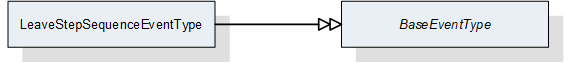
| Attribute | Value | ||||
| BrowseName | LeaveStepSequenceEventType | ||||
| IsAbstract | False | ||||
| References | NodeClass | BrowseName | DataType | TypeDefinition | ModellingRule |
|---|---|---|---|---|---|
| Subtype of the BaseEventType defined in OPC 10000-5 | |||||