Vision systems frequently require interaction with external systems during image acquisition. For example, it may be required to capture images in several different positions, i.e., moving the part between image capturing operations. In that case, the vision system will signal to the PLC when it has captured an image, so that the part may be safely moved, and the PLC will in turn signal to the vision system when the part is in the next position to capture the next image.
To enable the states of the VisionAutomaticModeStateMachineType to do such interaction, each is a complex state with an optional SubStateMachine of the VisionStepModelStateMachineType.
Figure 32 shows the entire SubStateMachine diagram.
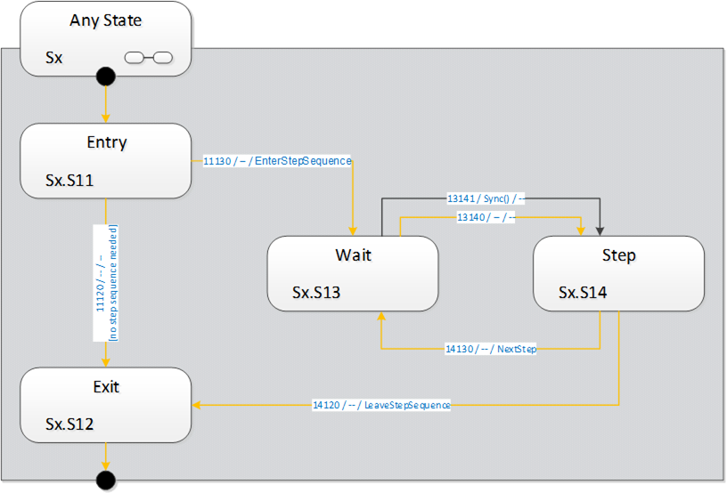
Figure 32 – States and transitions of the VisionStepModelStateMachineType
It is supposed that a SubStateMachine is entered automatically if it is present in the superior state. Since the Entry state is of InitialStateType it will be entered automatically.
Upon entering the SubStateMachine there is a check in the Entry state whether there is a step-sequence to execute. This is application-dependent and may depend on the situation (e.g. on the currently active recipe) and the way of determining this is application-specific.
If in the Entry state the system decides that there is a step sequence to be executed, the SubStateMachine informs the client about this by firing an EnterStepSequence event. It then enters the Wait state to wait for a synchronization event.
The synchronization can occur by a Sync method call from an OPC UA client, typically the control system. The synchronization can also occur internally, typically due to communication events on other interfaces, e.g. a digital trigger.
The system then enters the Step state, where it does the actual work required in this state of the step model and decides whether there are any steps left in the step sequence. This is application-specific, as is the original decision to execute a step sequence at all.
The system indicates the need for another step-sequence cycle by firing a NextStep event and re-enters the Wait state. In this manner, an arbitrary and dynamic number of steps can be executed. It is not necessary to predefine the number of steps.
To use the common example of image acquisition: There may be one image acquisition in each Step state, but it is also possible that the step sequence is used only for mechanical synchronization and all acquisition is done in the Exit state.
If no step-sequence is to be executed at all, the system will transition into the Exit state directly from the Entry state and perform the actual task of the superior state. After the task is finished, the superior state will transition to whatever is its target state, thus de-activating the SubStateMachine.
When a step sequence is being executed and the system decides in the Step state that there are no more steps to execute in the step sequence, it fires a LeaveStepSequence event, transitions to the Exit state and proceeds as in the case without a step sequence.
How the work of the superior state and of the steps of the sequence is distributed between the states of the step model is application-specific.
The superior state of a currently active VisionStepModelStateMachine is some state in the VisionStateMachineType or the VisionAutomaticModeStateMachineType.
Each of these states can be left due to internal causes (like error conditions) or external causes (like the Stop, Abort, Halt, Reset method calls). In that case, the SubStateMachine becomes inactive and will be in state Bad_StateNotActive, as explained in Section 8.1.2.
How and when these transitions take place is at the discretion of the vision system underlying the OPC UA server. In particular, the vision system can disable the Executable flag on each of these methods when the current operation does not allow for, e.g. an Abort command to be carried out.
This ObjectType is a subtype of FiniteStateMachineType and it is used to represent interactions of the vision system with external components/systems for synchronization purposes. It is formally defined in Table 114.
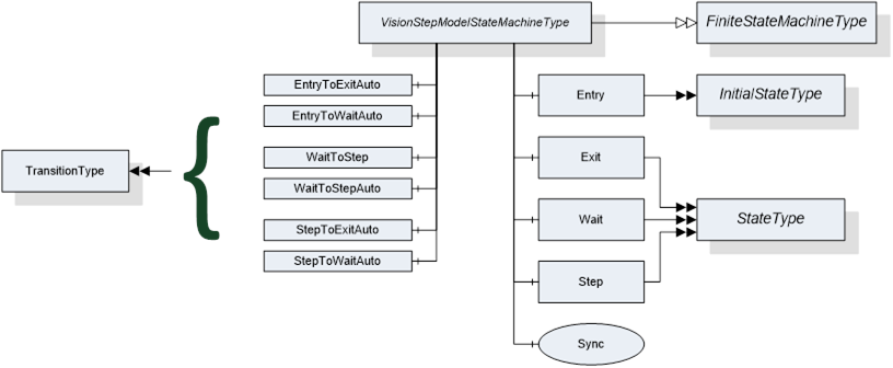
Figure 33 – Overview VisionStepModelStateMachineType
VisionStepModelStateMachineType is formally defined in Table 114.
Table 114 – VisionStepModelStateMachineType definition
|
Attribute |
Value |
||||
|
|
Includes all attributes specified for the FiniteStateMachineType |
||||
|
BrowseName |
VisionStepModelStateMachineType |
||||
|
IsAbstract |
False |
||||
|
References |
NodeClass |
BrowseName |
DataType |
TypeDefinition |
ModellingRule |
|
Subtype of the FiniteStateMachineType defined in OPC 10000-5 Annex B.4.5 |
|||||
|
HasComponent |
Object |
Entry |
-- |
InitialStateType |
-- |
|
HasComponent |
Object |
Exit |
-- |
StateType |
-- |
|
HasComponent |
Object |
Wait |
-- |
StateType |
-- |
|
HasComponent |
Object |
Step |
-- |
StateType |
-- |
|
HasComponent |
Object |
EntryToExitAuto |
-- |
TransitionType |
-- |
|
HasComponent |
Object |
EntryToWaitAuto |
-- |
TransitionType |
-- |
|
HasComponent |
Object |
WaitToStep |
-- |
TransitionType |
-- |
|
HasComponent |
Object |
WaitToStepAuto |
-- |
TransitionType |
-- |
|
HasComponent |
Object |
StepToExitAuto |
-- |
TransitionType |
-- |
|
HasComponent |
Object |
StepToWaitAuto |
-- |
TransitionType |
-- |
|
HasComponent |
Method |
Sync |
-- |
-- |
Mandatory |
Table 115 lists the states of VisionStepModelStateMachineType. See Table 116 for a brief description of the states. These will be detailed in the following subsections.
Table 115 – VisionStepModelStateMachineType states
|
BrowseName |
References |
Target BrowseName |
Value |
Target TypeDefinition |
Notes |
|
Entry |
HasProperty |
StateNumber |
11 |
PropertyType |
-- |
|
|
ToTransition |
EntryToExitAuto |
|
TransitionType |
-- |
|
|
ToTransition |
EntryToWaitAuto |
|
TransitionType |
-- |
|
Exit |
HasProperty |
StateNumber |
12 |
PropertyType |
-- |
|
|
FromTransition |
EntryToExitAuto |
|
TransitionType |
-- |
|
|
FromTransition |
StepToExitAuto |
|
TransitionType |
-- |
|
Wait |
HasProperty |
StateNumber |
13 |
PropertyType |
-- |
|
|
FromTransition |
EntryToWaitAuto |
|
TransitionType |
-- |
|
|
FromTransition |
StepToWaitAuto |
|
TransitionType |
-- |
|
|
ToTransition |
WaitToStep |
|
TransitionType |
-- |
|
|
ToTransition |
WaitToStepAuto |
|
TransitionType |
-- |
|
Step |
HasProperty |
StateNumber |
14 |
PropertyType |
-- |
|
|
FromTransition |
WaitToStep |
|
TransitionType |
-- |
|
|
FromTransition |
WaitToStepAuto |
|
TransitionType |
-- |
|
|
ToTransition |
StepToExitAuto |
|
TransitionType |
-- |
|
|
ToTransition |
StepToWaitAuto |
|
TransitionType |
-- |
Table 116 – VisionStepModelStateMachineType state descriptions
|
StateName |
Description |
|
Entry |
If a superior state has a step model SubStateMachine, this state will be entered automatically. In this state, the step model SubStateMachine decides whether a step model execution is required or not. This decision may depend on the current recipe or other factors. |
|
Exit |
In this state, the SubStateMachine signals to the superior state that its work is finished so that the superior state can be completed and transition to its target state. The superior state may also be left at any time due to other reasons regardless of the current state of the step model. |
|
Wait |
In this state, the system waits for a synchronization event. This may be a call to the Sync method or other internal or external factor, e.g. communication via a different interface. |
|
Step |
In this state, the system carries out the work for the current step, then decides based on the current situation whether more steps are required, in which case the state machine transitions back into state Wait, or not, in which case the state machine transitions to the Exit state. |
Table 117 lists the transitions of VisionStepModelStateMachineType.
Table 117 – VisionStepModelStateMachineType transitions
|
BrowseName |
References |
Target BrowseName |
Value |
Target TypeDefinition |
Notes |
|
EntryToExitAuto |
HasProperty |
TransitionNumber |
11120 |
PropertyType |
-- |
|
|
FromState |
Entry |
|
StateType |
-- |
|
|
ToState |
Exit |
|
StateType |
-- |
|
|
HasEffect |
StateChangedEventType |
|
|
-- |
|
EntryToWaitAuto |
HasProperty |
TransitionNumber |
11130 |
PropertyType |
-- |
|
|
FromState |
Entry |
|
StateType |
-- |
|
|
ToState |
Wait |
|
StateType |
-- |
|
|
HasEffect |
EnterStepSequenceEventType |
|
|
-- |
|
|
HasEffect |
StateChangedEventType |
|
|
-- |
|
WaitToStep |
HasProperty |
TransitionNumber |
13141 |
PropertyType |
-- |
|
|
FromState |
Wait |
|
StateType |
-- |
|
|
ToState |
Step |
|
StateType |
-- |
|
|
HasCause |
Sync |
|
Method |
-- |
|
|
HasEffect |
StateChangedEventType |
|
|
-- |
|
WaitToStepAuto |
HasProperty |
TransitionNumber |
13140 |
PropertyType |
-- |
|
|
FromState |
Wait |
|
StateType |
-- |
|
|
ToState |
Step |
|
StateType |
-- |
|
|
HasEffect |
StateChangedEventType |
|
|
-- |
|
StepToExitAuto |
HasProperty |
TransitionNumber |
14120 |
PropertyType |
-- |
|
|
FromState |
Step |
|
StateType |
-- |
|
|
ToState |
Exit |
|
StateType |
-- |
|
|
HasEffect |
LeaveStepSequenceEventType |
|
|
-- |
|
|
HasEffect |
StateChangedEventType |
|
|
-- |
|
StepToWaitAuto |
HasProperty |
TransitionNumber |
14130 |
PropertyType |
-- |
|
|
FromState |
Step |
|
StateType |
-- |
|
|
ToState |
Wait |
|
StateType |
-- |
|
|
HasEffect |
NextStepEventType |
|
|
-- |
|
|
HasEffect |
StateChangedEventType |
|
|
-- |
This method can be called to cause a transition from the Wait state in the step model to the ExecuteStep state.
Signature
Sync ([in]Int32cause[in]StringcauseDescription[out]Int32error);
Table 118 – Sync Method Arguments
|
Argument |
Description |
|
cause |
Implementation-specific number denoting circumstances of the command |
|
causeDescription |
Description of the circumstances, e.g. for logging purposes. May be empty. |
|
error |
0 – OK Values > 0 are reserved for errors defined by this and future standards. Values < 0 shall be used for application-specific errors. |
Table 119 – Sync Method AddressSpace Definition
|
Attribute |
Value |
||||
|
BrowseName |
Sync |
||||
|
References |
NodeClass |
BrowseName |
DataType |
TypeDefinition |
ModellingRule |
|
HasProperty |
Variable |
InputArguments |
Argument[] |
PropertyType |
Mandatory |
|
HasProperty |
Variable |
OutputArguments |
Argument[] |
PropertyType |
Mandatory |
The cause argument given to the method can only be interpreted by the underlying vision system It can be used, for example, for ending the step model prematurely.
EnterStepSequenceEventType is an EventType subtype of BaseEventType, defined in OPC 10000-5. This event is to be triggered by the server when in the Entry state the decision is taken that under the current circumstances (superior state, recipe etc.) a step sequence is to be executed and the transition into the first Wait state is initiated. The structure is defined in Figure 34. It is formally defined in Table 120.
Event properties
- Steps: number of steps to expect. If the number of steps is not known, this should be -1. Even if this is a positive value, the client should not rely on it because circumstances occurring during execution of the step model may change the number of steps required, for example a call to the Sync method with a particular mode argument.
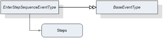
Figure 34 – Overview EnterStepSequenceEvent
Table 120 – EnterStepSequenceEventType definition
|
Attribute |
Value |
||||
|
BrowseName |
EnterStepSequenceEventType |
||||
|
IsAbstract |
False |
||||
|
References |
NodeClass |
BrowseName |
DataType |
TypeDefinition |
ModellingRule |
|
Subtype of the BaseEventType defined in OPC 10000-5 |
|||||
|
HasProperty |
Variable |
Steps |
Int32 |
PropertyType |
Mandatory |
NextStepEventType is an EventType subtype of BaseEventType, defined in OPC 10000-5. This event is to be triggered by the server when in the Step state the decision is reached that under the current circumstances (superior state, recipe, number of steps already taken, parameter of Sync method) another step has to be taken and the state machine must translate to the Wait state. It is formally defined in Table 121
Event properties
- State NodeId
- Running number of the step
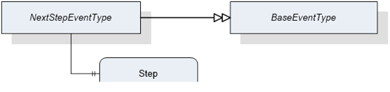
Figure 35 – Overview NextStepEvent
Table 121 – NextStepEventType definition
|
Attribute |
Value |
||||
|
BrowseName |
NextStepEventType |
||||
|
IsAbstract |
False |
||||
|
References |
NodeClass |
BrowseName |
DataType |
TypeDefinition |
ModellingRule |
|
Subtype of the BaseEventType defined in OPC 10000-5 |
|||||
|
HasProperty |
Variable |
Step |
Int32 |
PropertyType |
Mandatory |
LeaveStepSequenceEventType is an EventType subtype of BaseEventType, defined in OPC 10000-5, this event is to be triggered by the server when in the Step state the decision is reached that under the current circumstances (superior state, recipe, number of steps already taken, parameter of Sync method) no further steps have to be taken and the transition into the Exit state is initiated. It is formally defined in Table 122.
Figure 36 – Overview LeaveStepSequenceEventType
Table 122 – LeaveStepSequenceEventType definition
|
Attribute |
Value |
||||
|
BrowseName |
LeaveStepSequenceEventType |
||||
|
IsAbstract |
False |
||||
|
References |
NodeClass |
BrowseName |
DataType |
TypeDefinition |
ModellingRule |
|
Subtype of the BaseEventType defined in OPC 10000-5 |
|||||