Usually it is desirable to expose some information on the inner state of the machine vision framework to the outside world. A state machine only covers information on the current control state of the vision system. If an error occurs it transits to the Error state, but offers no information why this happened. Therefore we need additional communication elements that are capable of transporting error messages, warning messages to avoid the occurrence of an error, or any other kind of information helpful for the client.
The kind of errors that may occur and the additional information to be transported are highly application specific. Therefore it is out of scope for this standard to define such things. Instead we are defining a framework of rules on how to structure application specific messages and how messages should interact with the state machine. The goal for this is to make it possible that even a “generic” client without further knowledge of a specific application is able to get a basic picture of the current state of the vision system.
In general each client is free to decide if it reads information from an OPC UA server. There is no mechanism for a server to enforce that a specific client gets a message. But OPC UA offers different levels of client / user interaction that may be selected for information being published.
The message is published at the interface and no feedback is expected to inform the server if the information has been read by any client.
After it is published on the interface the server waits for one client to acknowledge the reception of the message. Usually such an acknowledgement is automatically generated by a client PLC reading the information.
If a message requiring an acknowledgement has been published it will stay active till an acknowledgement has been received, even if the cause triggering this message has already been cleared.
Application Note:
As a Reset method call tries to bring the system back to an initial state it clears all active messages. If an error state could not be cleared the message will show up again after performing the reset.
After the message is published one of the receiving clients has to acknowledge the reception and afterward has to confirm that the server may clear the information. This mechanism is usually used to call for human assistance. The client PLC acknowledges the reception and shows a message on its HMI. After the operator gives the command to continue the PLC sends the confirmation to inform the server.
If the vision System has its own user console such a user confirmation may be entered there. Therefor it is allowed that the vision system may clear the message even without the confirmation received from a client. But it has to wait for the reception of an acknowledgement before doing so.
As a number of messages may be published at the same time the vision system may optionally offer a ConfirmAll method that sets the confirmation for all active messages.
We are defining five classes of informational elements to be exposed on the interface. The classes are distinguished by their severity regarding the influence on the operation of the vision system.
Each message transports its severity represented as a value between 0 and 1000.
This class of lowest severity carries messages for debugging and diagnostic purposes. It may safely be ignored by clients.
This class may be used for messages that do not require that any client reads them for the normal operation. The vision system is able to safely continue normal operation even if this message is ignored.
A message of this class has a midlevel severity. The server can decide if for a specific message an acknowledgement, or acknowledgement and confirmation may be needed.
If on the vision system side a condition arises that could affect the normal operation of the system a message of this class should be created. An error message requires an acknowledgement from the client side. The server may decide that also a confirmation is needed.
This highest class of severity is used for error messages associated with problems that need human interaction. This kind of errors cannot automatically be solved, an operator has to do something in the physical world before the operation can go on. Acknowledgement and confirmation is mandatory for this class.
Table 128 – Information Elements
|
Information Type |
Severity |
needs Acknowledge |
needs Confirmation |
OPC UA Type |
|
Persistent Error |
801...1000 |
yes |
yes |
VisionPersistentErrorConditionType |
|
Error |
601...800 |
yes |
optional |
VisionErrorConditionType |
|
Warning |
401...600 |
optional |
optional |
VisionWarningConditionType |
|
Information |
201...400 |
no |
no |
VisionInformationEventType |
|
Diagnostic Information |
1…200 |
no |
no |
VisionDiagnosticInfoEventType |
VisionEvents are generated to signal noteworthy events during the operation of the vision system which do not require interaction.
All non-inherited properties are optional and stay optional on the concrete sub-types because these EventTypes will be used under very different operational circumstances in the vision system; it is therefore not possible to specify that, e.g. a jobId shall be mandatory, since an event may be triggered during the preparation of a recipe, when no job is running.
However, the intention is for the server to provide as much information to the client as possible, i.e. fill as many properties as possible.
The EventType for VisionEvents is formally defined in Table 129.
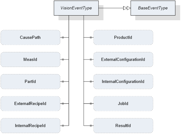
Figure 38 – Overview VisionEventType
Table 129 – VisionEventType Definition
|
Attribute |
Value |
||||
|
BrowseName |
VisionEventType |
||||
|
IsAbstract |
True |
||||
|
References |
NodeClass |
BrowseName |
DataType |
TypeDefinition |
ModellingRule |
|
Subtype of the BaseEventType defined in OPC 10000-5 |
|||||
|
HasSubtype |
ObjectType |
VisionDiagnosticInfoEventType |
Defined in 11.4.2 |
||
|
HasSubtype |
ObjectType |
VisionInformationEventType |
Defined in 11.4.3 |
||
|
|
|
|
|
|
|
|
HasProperty |
Variable |
CausePath |
String |
PropertyType |
Optional |
|
HasProperty |
Variable |
MeasId |
MeasIdDataType |
PropertyType |
Optional |
|
HasProperty |
Variable |
PartId |
PartIdDataType |
PropertyType |
Optional |
|
HasProperty |
Variable |
ExternalRecipeId |
RecipeIdExternalDataType |
PropertyType |
Optional |
|
HasProperty |
Variable |
InternalRecipeId |
RecipeIdInternalDataType |
PropertyType |
Optional |
|
HasProperty |
Variable |
ProductId |
ProductIdDataType |
PropertyType |
Optional |
|
HasProperty |
Variable |
ExternalConfigurationId |
ConfigurationIdDataType |
PropertyType |
Optional |
|
HasProperty |
Variable |
InternalConfigurationId |
ConfigurationIdDataType |
PropertyType |
Optional |
|
HasProperty |
Variable |
JobId |
JobIdDataType |
PropertyType |
Optional |
|
HasProperty |
Variable |
ResultId |
ResultIdDataType |
PropertyType |
Optional |
The following properties are inherited from BaseEventType and shall be used in VisionEventType in the manner described here.
SourceNode
Reference to the source of the Message. This could be a failing method or, in case of an internally triggered message, the state machine object itself.
SourceName
Name of the Message source.
Severity
Severity of the Information within the boundaries defined by Table 128.
Message
A textual description of the error as a string.
The following describes the usage of the properties added by VisionEventType with respect to BaseEventType.
CausePath
Path information string based on the E10 scheme described in 11.6 or an application specific expanded derivation of that.
MeasId, PartId, ExternalRecipeId, InternalRecipeId, ProductId, ExternalConfigurationId, InternalConfigurationId, JobId, ResultId
If the information is somehow linked to one of the (vision system) objects referenced by these Ids, these properties can transport this reference.
VisionDiagnosticInfoEvents are generated to signal events of the lowest severity class as described in Section 11.3.2.
The EventType for VisionDiagnosticInfoEvents is formally defined in Table 130.
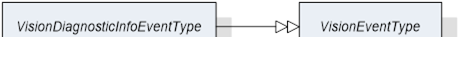
Figure 39 – Overview VisionDiagnosticInfoEventType
Table 130 – VisionDiagnosticInfoEventType
|
Attribute |
Value |
||||
|
BrowseName |
VisionDiagnosticInfoEventType |
||||
|
IsAbstract |
False |
||||
|
References |
NodeClass |
BrowseName |
DataType |
TypeDefinition |
ModellingRule |
|
Subtype of the VisionEventType |
|||||
VisionInformationEvents are generated to signal events of low severity class as described in Section 11.3.3.
The EventType for VisionInformationEvents is formally defined in Table 131.
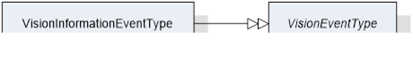
Figure 40 – Overview VisionInformationEventType
Table 131 – VisionInformationEventType
|
Attribute |
Value |
||||
|
BrowseName |
VisionInformationEventType |
||||
|
IsAbstract |
False |
||||
|
References |
NodeClass |
BrowseName |
DataType |
TypeDefinition |
ModellingRule |
|
Subtype of the VisionEventType |
|||||
VisionConditions are generated to signal important events during the operation of the vision system which require interaction, i.e. conditions.
All non-inherited properties are optional and stay optional on the concrete sub-types because these ConditionTypes will be used under very different operational circumstances in the vision system; it is therefore not possible to specify that, e.g. a jobId shall be mandatory, since an error condition may be triggered during the preparation of a recipe, when no job is running.
However, the intention is for the server to provide as much information to the client as possible, i.e. fill as many properties as possible.
The EventType for VisionConditions is formally defined in Table 132.
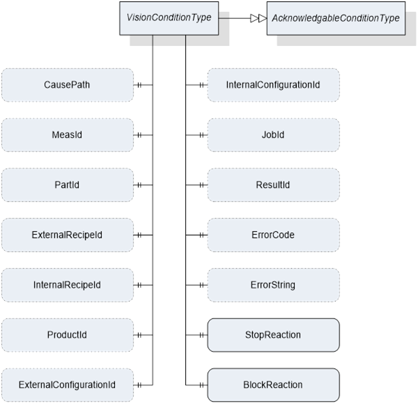
Figure 41 – Overview VisionConditionType
Table 132 – VisionConditionType
|
Attribute |
Value |
|||||
|
BrowseName |
VisionConditionType |
|||||
|
IsAbstract |
True |
|||||
|
References |
NodeClass |
BrowseName |
DataType |
TypeDefinition |
ModellingRule |
|
|
Subtype of the AcknowledgeableConditionType defined in OPC 10000-9 |
||||||
|
HasSubtype |
ObjectType |
VisionWarningConditionType |
Defined in 11.4.5 |
|||
|
HasSubtype |
ObjectType |
VisionErrorConditionType |
Defined in 11.4.6 |
|||
|
HasSubtype |
ObjectType |
VisionPersistentErrorConditionType |
Defined in 11.4.7 |
|||
|
|
|
|
|
|
|
|
|
HasProperty |
Variable |
CausePath |
String |
PropertyType |
Optional |
|
|
HasProperty |
Variable |
MeasId |
MeasIdDataType |
PropertyType |
Optional |
|
|
HasProperty |
Variable |
PartId |
PartIdDataType |
PropertyType |
Optional |
|
|
HasProperty |
Variable |
ExternalRecipeId |
RecipeIdExternalDataType |
PropertyType |
Optional |
|
|
HasProperty |
Variable |
InternalRecipeId |
RecipeIdInternalDataType |
PropertyType |
Optional |
|
|
HasProperty |
Variable |
ProductId |
ProductIdDataType |
PropertyType |
Optional |
|
|
HasProperty |
Variable |
ExternalConfigurationId |
ConfigurationIdDataType |
PropertyType |
Optional |
|
|
HasProperty |
Variable |
InternalConfigurationId |
ConfigurationIdDataType |
PropertyType |
Optional |
|
|
HasProperty |
Variable |
JobId |
JobIdDataType |
PropertyType |
Optional |
|
|
HasProperty |
Variable |
ResultId |
ResultIdDataType |
PropertyType |
Optional |
|
|
HasProperty |
Variable |
ErrorCode |
UInt64 |
PropertyType |
Optional |
|
|
HasProperty |
Variable |
ErrorString |
String |
PropertyType |
Optional |
|
|
HasProperty |
Variable |
StopReaction |
Boolean |
PropertyType |
Mandatory |
|
|
HasProperty |
Variable |
BlockReaction |
Boolean |
PropertyType |
Mandatory |
|
The properties which VisionConditionType has in common with VisionEventType have the same semantics and usage as described in Sections 11.4.1.2 and 11.4.1.3..
The following describes the usage of the properties added by VisionConditionType with respect to AcknowledgeableConditionType.
ErrorString
A system specific string classifying the error / warning.
ErrorCode
A system specific numeric code classifying the error / warning.
StopReaction
If the system did stop normal operation because of this error (state machine did transit to error state) this property shall be set to true.
BlockReaction
If the system did stop normal operation and user interaction is needed because of this error this property shall be set to true.
The VisionWarningConditionType is used to represent conditions in the vision system which the client should be warned about as described in Section 11.3.4.
The server can use the AckedState and ConfirmedState variables of the AcknowledgeableConditionType to control whether the vision system requires acknowledgement and confirmation of the condition as described in OPC 10000-9.
The VisionWarningConditionType is formally defined in Table 133.
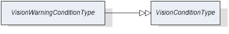
Figure 42 – Overview VisionWarningConditionType
Table 133 – VisionWarningConditionType
|
Attribute |
Value |
||||
|
BrowseName |
VisionWarningConditionType |
||||
|
IsAbstract |
False |
||||
|
References |
NodeClass |
BrowseName |
DataType |
TypeDefinition |
ModellingRule |
|
Subtype of the VisionConditionType |
|||||
The VisionErrorConditionType is used to represent error conditions in the vision system as described in Section 11.3.5.
The server can use the AckedState and ConfirmedState variables of the AcknowledgeableConditionType to control whether the vision system requires acknowledgement and confirmation of the condition as described in OPC 10000-9.
The VisionErrorConditionType is formally defined in Table 134.

Figure 43 – Overview VisionErrorConditionType
Table 134 – VisionErrorConditionType
|
Attribute |
Value |
||||
|
BrowseName |
VisionErrorConditionType |
||||
|
IsAbstract |
False |
||||
|
References |
NodeClass |
BrowseName |
DataType |
TypeDefinition |
ModellingRule |
|
Subtype of the VisionConditionType |
|||||
The VisionPersistentErrorConditionType is used to represent error conditions in the vision system requiring outside interaction as described in Section 11.3.6.
The server can use the AckedState and ConfirmedState variables of the AcknowledgeableConditionType to control whether the vision system requires acknowledgement and confirmation of the condition as described in OPC 10000-9.
The VisionPersistentErrorConditionType is formally defined in Table 135.

Figure 44 – Overview VisionPersistentErrorConditionType
Table 135 – VisionPersistentErrorConditionType
|
Attribute |
Value |
||||
|
BrowseName |
VisionPersistentErrorConditionType |
||||
|
IsAbstract |
False |
||||
|
References |
NodeClass |
BrowseName |
DataType |
TypeDefinition |
ModellingRule |
|
Subtype of the VisionConditionType |
|||||
VisionSafetyEventType is an EventType subtype of BaseEventType, defined in OPC 10000-5. This event is to be triggered by the server when a safety-related incident occurs in the vision system. The structure is defined in Figure 45. It is formally defined in Table 136.
Event properties
- VisionSafetyTrigger: flag indicating the current internal safety state
- VisionSafetyInformation: information about the internal safety state provided by the vision system
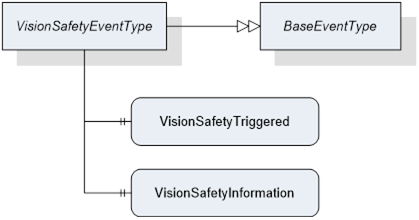
Figure 45 – Overview VisionSafetyEventType
Table 136 – VisionSafetyEventType Definition
|
Attribute |
Value |
||||
|
BrowseName |
VisionSafetyEventType |
||||
|
IsAbstract |
False |
||||
|
References |
NodeClass |
BrowseName |
DataType |
TypeDefinition |
ModellingRule |
|
Subtype of the BaseEventType defined in OPC 10000-5 |
|||||
|
HasProperty |
Variable |
VisionSafetyTriggered |
Boolean |
PropertyType |
Mandatory |
|
HasProperty |
Variable |
VisionSafetyInformation |
String |
PropertyType |
Mandatory |
There is only a loose connection between the generation of messages and the exposed behavior of the vision system on the state machine level. The following mandatory behavior is defined:
As the OPC UA interface only offers a view to the underlying vision system each call of the defined methods may fail. The method may deliver some information on the cause of the fail, but this information is only visible for the client calling the method. If any other clients are interested in this kind of information there is no way for them to get it. Therefore we define that if a method call fails the vision system has to generate a message at least of the warning without acknowledgement type naming the failed method including the calling parameters.
As the definition of the vision system is out of the scope of this document this is also true for the detection of error states within the vision system. As a consequence of this the generation of messages signaling such conditions is not associated to a specific state of the state machine.
As a general rule the transition to the error state of the state machine should only be performed if this is inevitable for the operation. The creation of an error message does not require that the state machine transitions to the Error state. A problem may be detected in a part of the vision system that is not needed for the current task at hand. Only if in this situation a method is called that can’t be performed because of this problem a transition to the Error state should occur.
On the other hand if the state machine does a transition to the Error state it is mandatory that a message of the error type or higher severity describing the cause is generated or already active.
It is up to the vision system to define if an internal error condition can be resolved immediately or if it has to wait for external acknowledgement / confirmation before trying to do so. Even if the system is successful in clearing the condition internally it has to wait for the reception of the acknowledgement of the corresponding message object if this is of an acknowledgeable type, before the message is cleared.
Application Note:
As the reception of an acknowledgement / confirmation can only take place once for each message object on the interface the vision system after reception has to check if the error condition is / can be resolved. If it is unable to resolve the error and interaction of the client / user side is required for resolving, it has to clear the message and create a new one to start a new resolving cycle.
Example:
During normal operation a vision system detects that it cannot accept a new job because the camera lens is dirty. It generates an error message informing the client on this with Ack and Conf required.
The client acknowledges the message and shows a message box on its console asking the operator to clean the lens.
The Operator presses the confirmation button without reading the message.
The client sends the confirmation for the message.
After reception of confirmation the vision System takes a test image and detects that the lens is still dirty. As there is still the need for user interaction the vision system has to decide what to do.
If it does nothing the client still sees the confirmed error message and therefore knows that it was not resolved. But as there are no additional confirmation options for the client the vision system will never get informed that if it may continue.
Therefore the vision system clears the confirmed message and creates a new one to start a new cleaning request with a hopefully better result.
The generation of large amounts of diagnostic messages may have impact on the performance of the vision system. As an OPC UA client can decide on its own if he reads such messages this is only a problem on the server side. It is common practice that the generation of such debugging / diagnostic messages can be suppressed within the vision System software. The server shall expose the information on suppressing of such messages in the following way. An integer variable DiagnosticLevel with a valid range between 1 … 200 is published showing that all diagnostic messages with a severity level lower or equal to this value are suppressed. Optionally this variable may be defined to be client writable to set a desired diagnostic level externally. For values lower than 150 it is not mandatory that the vision System is capable of upholding the performance expected for the application. The initial value of this variable on system start should be 200.
Application Note:
Example of a failing method call
Let’s assume the vision system is in the Ready state with an activated recipe in its memory. A client can call the PrepareRecipe method to load a second recipe but with a wrong recipe name that is not present in the vision system.
The method call will fail with an error message informing the calling client that this is a unknown recipe.
The vision system issues a warning message with a severity of e.g. 503 containing the information that a call of the PrepareRecipe method for that Recipe name failed.
The vision system does not transit to the Error state as there is no need to do so, since normal operation is not compromised at the moment. The vision system is able to accept jobs using the already activated recipe.
If the client now calls the StartSingleJob method with the unknown recipe the vision system could consider this an error and transition to the Error state while issuing a message of the error class. This decision is application specific. It is also valid that it only lets the method call fail and issues a warning message without transition to the Error state.
An external recipe management system could receive such a warning message and push the missing recipe to the vision system using the AddRecipe method.
System state information is often used to benchmark the reliability of a system. Therefore on a time scale it is estimated how long the system was productive, defective or in maintenance. To support this, a system should be able to publish its current state in a way enabling a client to do such estimation.
This standard follows the scheme of 6 basic system states defined by SEMI E10 standard (SEMI E10: Specification for Definition and Measurement of Equipment Reliability, Availability, and Maintainability (RAM) and Utilization). The following diagram shows how the total time of existence of a system is divided into different categories. From the left to the right the model gets more detailed.
|
E10 |
|||||
|
Total Time |
Operations Time |
Uptime |
Manufacturing Time |
Production |
PRD |
Standby |
SBY |
Engineering |
ENG |
Downtime |
Scheduled Downtime |
SDT |
Unscheduled Downtime |
UDT |
Nonscheduled Time |
NST |
If the optional SystemState variable exists on the server, the vision system shall continuously map its internal state to one of the six generic states on the right. This current state shall be published in the SystemState variable in the interface.
The vision system is currently working on a job.
The vision system is ready to accept a command but is currently not executing a job. It could for example be waiting for a Start command or a user input.
The vision system is not working and not ready to accept a command because a user is currently working on the system. This could be for editing a recipe or changing the system configuration.
The vision system is not available for production and this was planned in advance. This could be for cleaning, maintenance or calibration works.
The vision system is not available for production due to failure and repair. This covers all kinds of error states that might occur during operation.
The vision system is not working because no production was scheduled. This also covers things like operator training on the system.
Example:
An application specific extension of the base states:
|
E10 |
vendor / application specific extension |
|
|
PRD |
Acquisition |
ACQ CAM A |
|
|
|
ACQ CAM B |
|
|
Processing |
|
|
SBY |
Waiting for PREPARE |
|
|
|
Waiting for START |
|
|
ENG |
Recipe Editing |
|
|
|
Calibration |
|
|
SDT |
Maintenance |
|
|
|
Cleaning |
Optics A |
|
|
|
Optics B |
|
UDT |
Software Related Error |
|
|
|
Hardware Related Error |
|
|
NST |
Powered Off |
|
|
|
Operator Training |
|
If the system is in state “ACQ CAM A” the current path would be “PRD/Acquisition/ACQ CAM A”
The tree-like E10 scheme may be extended to the right by getting more specific on the current state of action the system is performing. As in the original E10 scheme, at every time the system has to choose exactly one state (rightmost field of a branch) it is currently in. To be compatible to clients understanding only the basic E10 states the system has to give the “/” separated path running along the branch of that tree starting from the base E10 state to the current state.
The same scheme should be used to structure error states. Every error information carries such path information to enable generic clients without deeper application knowledge to get a basic understanding of the possible error cause. The following basic error paths shall be used. As above this model may be expanded to the right as needed.
|
UDT |
Software Related Error |
|
|
|
Hardware Related Error |
Computing Unit |
|
|
|
Sensor Unit |
|
|
|
Controller Unit |
|
|
|
Lighting Unit |
The system can only be in one specific state (leaf of the tree), although errors can occur in more than one leaf simultaneously. In this case the system still has to select exactly one system state to be published.
There are two different approaches possible:
- The system selects the most severe error and publishes its path as the current system state.
- The system truncates the path to the last element common for all active errors.
The system may select one approach fitting to the current application.
Example:
A system is in an Error State and there are currently two errors active. The system uses application specific extended error classes:
- UDT/Hardware Related Error/ Sensor Unit/Camera A/Fan Fail
- UDT/Hardware Related Error/Lighting Unit/LED A/Over Temperature
The system decides that an over temperature is the most severe error and publishes “UDT/Hardware Related Error/Lighting Unit/LED A/Over Temperature“ as its system state.
The system publishes the truncated path “UDT/Hardware Related Error” as its current system state.