
1 Scope
This part of OPC 10000 summarises the OPC Unified Architecture Field Level Communications Initiative field extensions referred to as Field eXchange (UAFX). Reading this document helps understand the basic concepts of UAFX and how the remaining parts of this multi-part document set specify them. Each of the other parts is briefly explained. This part is non-normative.
This release of the UAFX specifications is focused on Controller-to-Controller communication (see 6.1) to exchange process and configuration/parameterisation data (non-safety and safety) using OPC UA PubSub in combination with UAFX Connections and basic diagnostics. A future version of the UAFX specifications is expected to address other communication interactions (see 5.3) and OPC UA Client Server for UAFX data exchange.
2 Reference documents
The following referenced documents are indispensable for the application of this OPC UA part. For dated references, only the edition cited applies. For undated references, the latest edition of the referenced document (including any amendments and errata) applies.
OPC 10000-1, OPC Unified Architecture - Part 1: Overview and Concepts
OPC 10000-1
OPC 10000-2, OPC Unified Architecture - Part 2: Security Model
OPC 10000-2
3 Terms, definitions, and abbreviated terms
3.1 Terms and definitions
For the purposes of this document, the terms and definitions given in OPC 10000-1, OPC 10000-7, OPC 10000-12, OPC 10000-14, OPC 10000-15, OPC 10000-81, and OPC 10000-100 as well as the following, apply.
All used terms are italicised in this document as described in OPC 10000-1.
3.1.1 Asset
Physical or logical elements of an AutomationComponent
3.1.2 AutomationComponent
entity that performs one or more automation functions and is modelled by an AutomationComponentType
3.1.3 Compute
software application collecting data, running on a variety of hardware platforms
3.1.4 Controller
industrial digital computer used in the control of manufacturing or process automation processes
3.1.5 ConnectionManager
entity that interacts with AutomationComponents to establish Connections between FunctionalEntities
3.1.6 Controller-to-Compute
interaction model involving Controllers exchanging data with Computes
3.1.7 Controller-to-Controller
interaction model involving Controllers exchanging data with one another
3.1.8 Controller-to-Device
interaction model involving Controllers exchanging data with devices
3.1.9 Connection
logical communication relationship between FunctionalEntities for exchanging information and coordinating joint operations
3.1.10 Descriptor
multi-document file (zip package) containing information for using and configuring one or more AutomationComponents
3.1.11 Device-to-Compute
interaction model involving devices exchanging data with Computes
3.1.12 Device-to-Device
interaction model involving devices exchanging data with one another
3.1.13 FunctionalEntity
element of an AutomationComponent containing the data and methods needed to configure, control and manage functional behaviour
3.1.14 OfflineEngineering
design phase activity, where, based on data from the vendors of the AutomationComponents, the configuration for AutomationComponents is planned (typically without the hardware available), which gets deployed to the physical Controller, device, or Compute during the commissioning phase at a plant
3.2 Abbreviated terms
| 5G | Fifth Generation broadband cellular network |
| AC | AutomationComponent |
| APL | Advanced Physical Layer |
| C2C | Controller-to-Controller |
| C2D | Controller-to-Device |
| DCS | Distributed Control System |
| DHCP | Dynamic Host Configuration Protocol |
| CM | ConnectionManager |
| DNS | Domain Name Service |
| FE | FunctionalEntity |
| FX | Field eXchange |
| HMI | Human Machine Interface |
| IEC | International Electrotechnical Commission |
| IEEE | Institute of Electrical and Electronics Engineers |
| IIoT | Industrial Internet of Things |
| IPC | Industrial Personal Computer |
| MES | Manufacturing Execution System |
| PAS | Process Automation System |
| PLC | Programmable Logic Controller |
| QoS | Quality of Service |
| SCADA | Supervisory Control And Data Acquisition |
| SPE | Single Pair Ethernet |
| TSN | Time-Sensitive Networking |
| UAFX | OPC UA Field eXchange |
| VLAN | Virtual Local Area Network |
| WLAN | Wireless Local Area Network |
3.3 Conventions used in this document
In this specification, the name of a type without the inclusion of "Type" indicates an instance of the type. For example, the following phrase, "an instance of ConnectionConfigurationSetType," can be replaced with "a ConnectionConfigurationSet". The phrase "instances of ConnectionEndpointType" can be replaced with "ConnectionEndpoints".
4 Structure of the OPC UA FX specification
4.1 OPC UA FX specification parts
The OPC UA FX specification is a multi-part document made up of 5 parts.
Part 80 (OPC 10000-80) - UAFX Overview and Concepts
Part 80 (this part) presents the OPC UA Field eXchange (UAFX) summary.
Part 81 (OPC 10000-81) - UAFX Connecting Devices and Information Model
Part 81 specifies the UAFX Information Model and describes how it can be used to meet the communication requirements of industrial automation.
Part 82 (OPC 10000-82) - UAFX Networking
Part 82 defines the general networking requirements for UAFX.
Part 83 (OPC 10000-83) - UAFX OfflineEngineering
Part 83 specifies the data structures used for sharing information that supports the OfflineEngineering of UAFX systems.
Part 84 (OPC 10000-84) - UAFX Profiles
Part 84 specifies the OPC UA and networking profiles required for OPC UA FX compliance.
4.2 Architecture
Figure 1 shows the UAFX communication stack architecture and how it relates to the layer model of OPC UA.
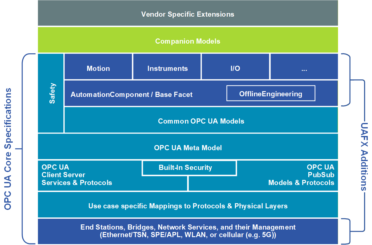
OPC UA FX extends the core OPC UA functionality for field-level communications. The foundation of the UAFX Information Model is the AutomationComponent. The AutomationComponent is an entity representing one or more Assets that may perform automation functions represented by FunctionalEntities. The AutomationComponent can also provide health status. See OPC 10000-81 for more details regarding the AutomationComponent model.
OPC UA FX also adds definitions for network services and component models for End Stations and Bridges. Profiles defining the selection of specific networking services supported by these component models are specified in OPC 10000-84.
UAFX supports the exchange of standard and safety process data simultaneously using the OPC safety communication layer - see OPC 10000-15 for details on the OPC safety communication layer.
Profiles will be developed in the future for Motion, I/O, and many types of process instruments. Specifications, including Information Models, developed for those types of products will build upon the AutomationComponent model.
5 Overview
5.1 Motivation
Today's automation devices use a wide variety of different fieldbus systems and real-time Ethernet protocols to communicate on the control and field level. Although most of these fieldbus systems and real-time Ethernet protocols are standardised by IEC (61158/61784 series), many devices are not interoperable with each other. Many of these protocols support different network infrastructures. However, even if they support the same infrastructure, they cannot coexist in the same network. Also, device information is structured using different syntax and semantics, making data analysis a labour-intensive and time-consuming task vulnerable to error, especially in multi-vendor and multi-protocol environments.
The trend towards Industry 4.0 and IIoT requires concepts for vendor-independent end-to-end interoperability from sensor to cloud, including field-level devices for all relevant industrial automation use cases, including real-time, motion, security, and safety. A standardised communication protocol from sensor to cloud supports the digital transformation across all industries, including process control and discrete manufacturing. End-users and system integrators benefit from easier Controller integration and cross-vendor Controller-to-Controller interoperability. Seamless access to production data and process conditions facilitates less downtime and optimisation of production processes.
This approach requires standardisation on different levels, including semantics and information modelling, application profiles, communication protocols, and data link/physical level connections. An important aspect is the convergence of information technology (IT) and operational technology (OT), allowing a common network infrastructure to be shared by IT and OT traffic while guaranteeing different levels of Quality of Service demanded by diverse IT and OT applications.
5.2 The UAFX Solution
OPC UA FX specifies a standardised Information Model and connection model for AutomationComponents, providing timely data delivery, security, and functional safety. Interactions addressed by UAFX include Controller-to-Controller, Controller-to-Device, Controller-to-Compute, Device-to-Device, and Device-to-Compute. This release of the specification includes Controller-to-Controller interactions. Other interactions will be included in future releases.
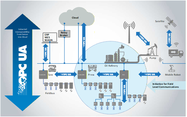
Figure 2 shows the scope of UAFX relative to the overall OPC UA integration patterns. UAFX extends the existing OPC UA communication solution (e.g., OPC 10000-14 and OPC 10000-100) to address industrial automation requirements in the discrete manufacturing and process industries, providing vendor-independent end-to-end interoperability of field-level devices for all relevant industrial automation use cases.
5.3 Interaction Model
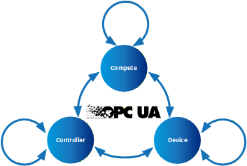
In the interaction model shown in Figure 3, a Controller represents a control automation component typically implemented in a PLC or DCS controller. Today, Devices may be connected to Controllers and can be as simple as an inductive proximity switch or as complex as a Coriolis flowmeter or servo drive. In the future, Devices may communicate directly with Compute application, eliminating the overhead of a Controller acting as an intermediary. Compute's hardware aspect scales from a single-board computer-based data gateway to a blade server in the cloud. Examples of Compute applications include historians, analytics, and complete MESs.
These interactions can be depicted by dividing the participants into different categories: Controller-to-Controller, Controller-to-Device, Controller-to-Compute, Device-to-Device, and Device-to-Compute. The interactions within these categories are similar in many ways, but each category will include interactions unique to its use cases. Controllers and devices may have vastly different functions and roles; however, their functionality is modelled at an abstract level in UAFX as an AutomationComponent (see 6.2). While capabilities specific to Compute-to-Compute are not part of UAFX, these interactions will inherit and benefit from the increased harmonisation delivered at the field level.
5.4 Engineering workflow
5.4.1 General
UAFX defines a mechanism for standardising the exchange of information used for establishing Connections between AutomationComponents (see 6.2) in an OfflineEngineering environment (see 6.4). From initial AutomationComponent development to on-site commissioning, engineers exchange offline data using the Descriptor (see 6.4). See OPC 10000-83 for more details regarding OfflineEngineering and Descriptors.
Assets and FunctionalEntities being used in applications, their available input, output, and configuration data, and communication capabilities are shared between engineers using Descriptors. The Descriptor allows product and system configuration data to be added by different engineers using their engineering tools at each phase of the workflow until the configuration ultimately can be deployed in the field.
5.4.2 Actors
5.4.2.1 Overview
This subclause defines actors interacting with a UAFX system during the system's engineering, which are referenced for workflow phase descriptions in all parts of the UAFX specifications.
5.4.2.2 Controls Engineer
Controls Engineers are responsible for the design of an automation or control system. Their primary responsibility is the programming/configuration of the application code in a PLC, PAC or DCS (etc.), which is necessary to execute algorithms that define the operation of a piece of equipment. In support of this function, they are typically responsible for integrating automation devices into the controller engineering tools and parameterising those devices with all information necessary for their correct functional operation.
There are multiple disciplines within the Controls Engineer category, including safety engineer, PLC programmer and process automation engineer, all of whom fulfil essentially the same function but with differing expertise.
5.4.2.3 Network Engineer
The Network Engineer, a peer to the Controls Engineer, is responsible for designing and configuring the network infrastructure and implementing network technologies. At the machine or skid level, the Network Engineer is often the same individual as the Controls Engineer.
5.4.2.4 Security Administrator
The Security Administrator has no direct stake in production operations or technologies. They are responsible for ensuring that there is no unauthorised access to production operations (whether from an outside hacker, inside bad actor or former employee). They are also charged with ensuring that the propagation of viruses, worms, malware, ransomware, etc., is restricted and that reasonable measures are taken to ensure resilience against these threats. They are responsible for the security of proprietary data entering and leaving facilities.
5.4.2.5 System Commissioner
The System Commissioner or commissioning engineer is responsible for the start-up of a system once it has been installed in a manufacturing/processing plant. In some cases, the System Commissioner may have operated as Controls Engineer earlier in the project lifecycle. For machine/skid builders, the commissioning engineer may never have met the Controls Engineer in person as they may work in different locations, or the machine design may be many years old.
5.4.3 Application engineering
Figure 4 shows an example of an engineering workflow where Controls Engineers A and B jointly create a control application consisting of Controller A and Controller B while separated in time and space and potentially without the physical devices. Using Controller A's engineering tool, Engineer A creates the User Program for Controller A and describes the inputs and outputs to be shared. Engineer A then exports an updated, signed Descriptor with the shared information. Engineer B then imports this Descriptor using Controller B's engineering tool and adds the information needed for Controller A and B Connections. Engineer B may import additional Descriptors describing components used with their Controller or other Controllers to be connected. Engineer B then adds the Connection configuration needed to exchange the data required for the application.
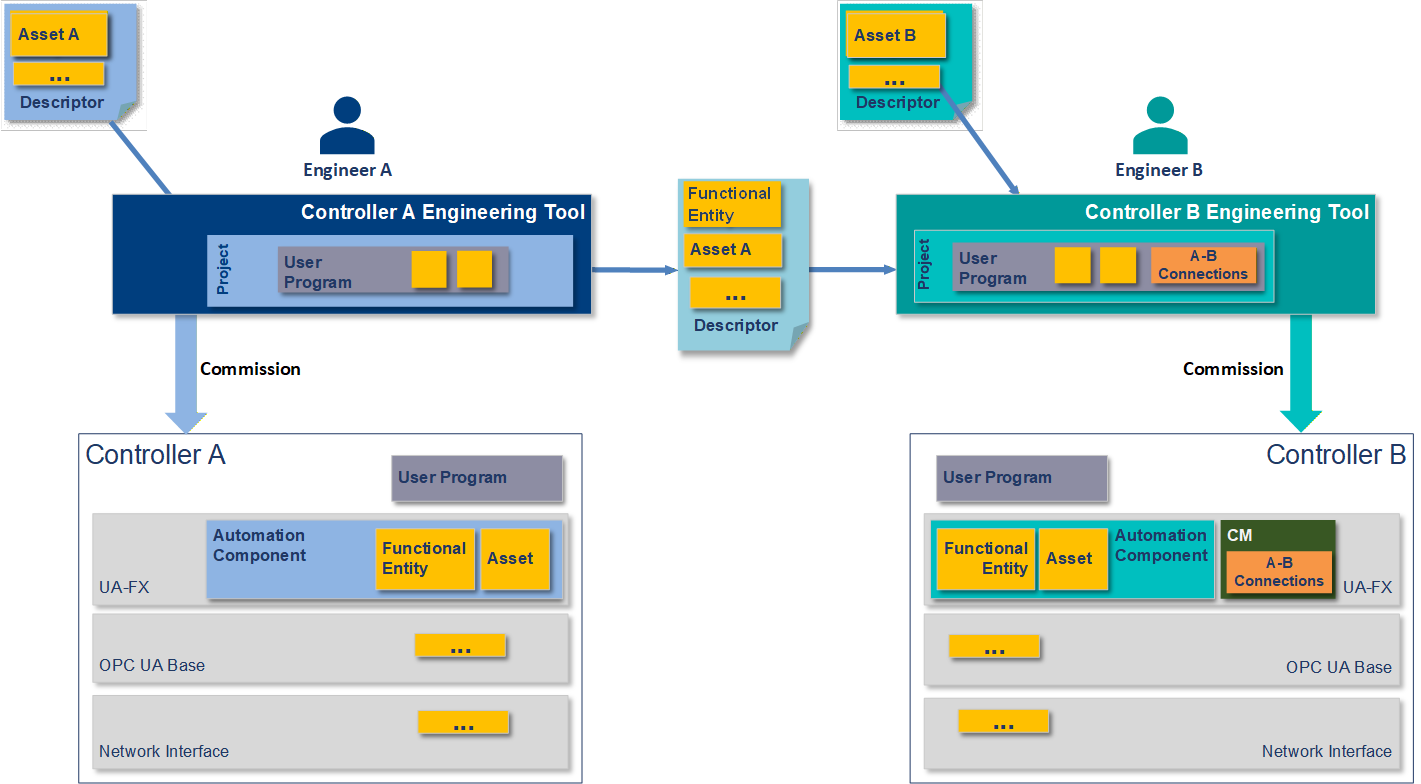
Engineer A and Engineer B deploy their applications to their respective Controllers and deliver them to the site. Initial network address assignment is a precondition for the following steps.
5.4.4 Security configuration
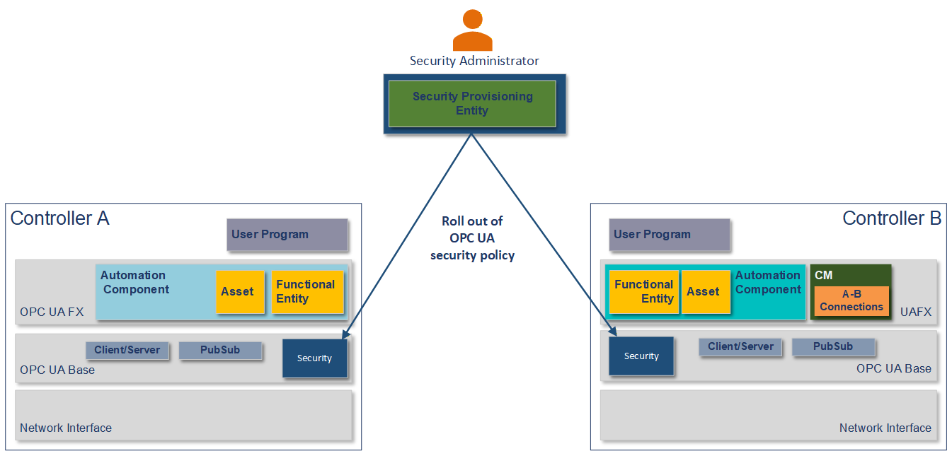
Using a Security Provisioning Entity, the Security Administrator configures the Controllers for OPC UA security and rolls out the security policy required for the site per Controller, as shown in Figure 5. The security policy contains, amongst others, certificates, roles, and user management. For PubSub, this includes the configuration of the SecurityKeyServer (see OPC 10000-14). The Security Administrator might use a GlobalDiscoveryServer (see OPC 10000-12) for security configuration.
5.4.5 Network configuration
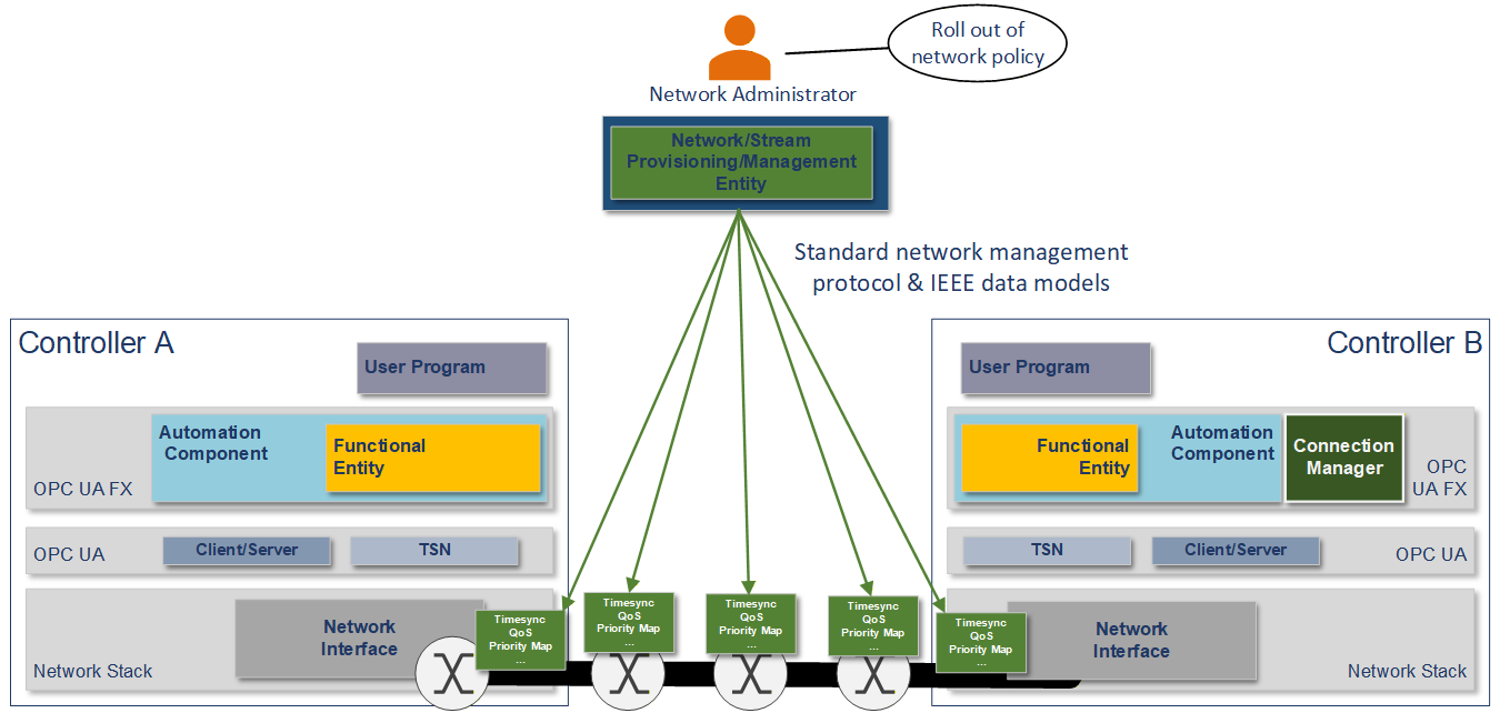
The Network Engineer commissions the Controllers with a hostname, DNS information, and an IP address or address acquisition mechanism such as DHCP. The Network Engineer may apply firmware or software updates if needed.
The Network Engineer then rolls out the network configuration as required for the site using vendor-independent mechanisms and tools, such as a Network Provisioning Entity, as shown in Figure 6. The network configuration contains, amongst others, VLAN usage, the configuration of time synchronisation, and the configuration of QoS (see 6.3).
5.4.6 System integration
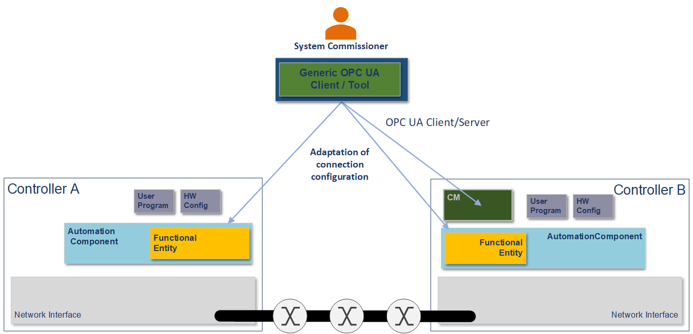
The System Commissioner may adjust the Connection configuration, such as addresses of Connection partners, publishing intervals, and QoS mapping tables using a generic OPC UA client or a tool based on standard OPC UA Client Server services, as shown in Figure 7.
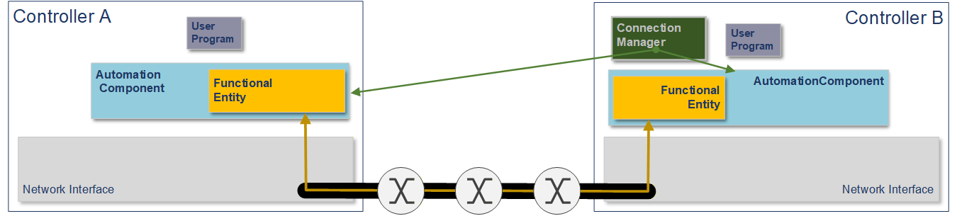
The ConnectionManager uses OPC UA Methods exposed by each AutomationComponent to establish the configured Connections when the system goes operational, as shown in Figure 8. See clause 6.2 for more details on Connections and the ConnectionManager.
See OPC 10000-81 for more details.
6 UAFX Concepts
6.1 Controller-to-Controller communication
Plant owners and system integrators assemble complex systems using best-of-breed solutions from multiple vendors in today's modern plants. Successfully integrating products like PLCs, DCS controllers, or PAS applications from different vendors can require a great deal of effort. Industrial automation has not effectively solved this problem to date. UAFX Controller-to-Controller communication delivers a genuinely multi-vendor interoperable, real-time solution.
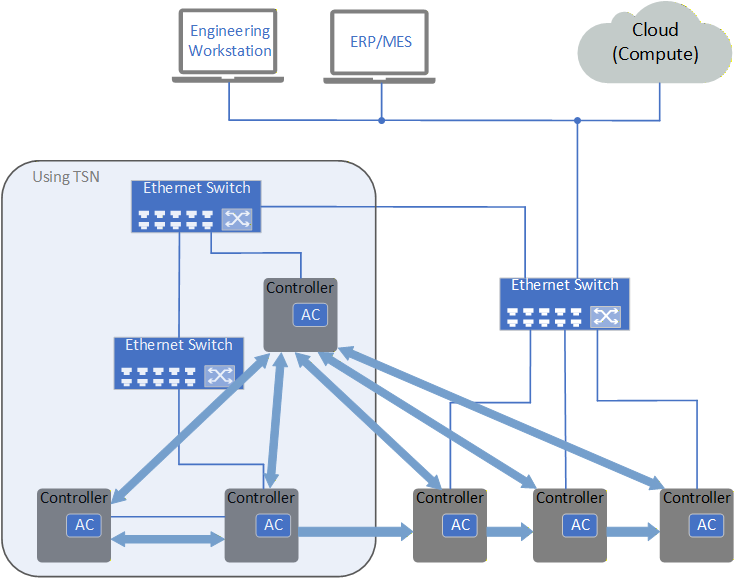
The UAFX specification addresses multi-controller environments, as shown in Figure 9. The Controllers in this illustration may be an IPC with visualisation, a PLC, a DCS controller, or something else. All communication partners are modelled as AutomationComponents defined in OPC 10000-81. An AutomationComponent provides an abstract model that allows vendors to describe the Controller's assets, automation functions, and a standard interface for Connections that provides interoperability for exchanging data. AutomationComponents, Assets, and FunctionalEntities also include identification information, allowing compatibility to be verified for each Connection.
This release of the UAFX specification defines Connections using OPC UA PubSub for data exchange, including the usage of TSN. Connections using OPC UA Client Server for data exchange are planned for future releases of the specification. Exchanged data can be standard process data or SafetyData. Both bidirectional and unidirectional traffic can be used (see OPC 10000-81). TSN can provide guaranteed bounded latency delivery of data within an Ethernet network. For network convergence, UAFX will follow the IEC/IEEE 60802 TSN Profile for Industrial Automation (see 6.3).
When layered over Ethernet-APL, UAFX provides an intrinsically safe communications solution for hazardous zones and divisions. Furthermore, functionally safe communications using PubSub, and eventually Client Server, can be addressed by adding the OPC UA Safety protocol (see OPC 10000-15). Authenticated and encrypted Connections and Client Server messages provide Cyber Security protection using standard OPC UA security mechanisms (see OPC 10000-2).
6.2 UAFX Information Model
OPC 10000-81 defines the base Information Model and communication concepts that UAFX provides to meet the use cases of process and factory automation applications. These communication concepts utilise the communication models defined in OPC UA, such as PubSub or Client Server1. The UAFX Information Model is based on the basic building blocks provided in OPC 10000-5 and utilises Interfaces and ObjectTypes described in OPC 10000-100. This base Information Model can, in turn, be utilised and extended in other specifications (e.g., motion or process instruments). Additionally, the UAFX Information Model may be used together with existing companion specifications, where existing definitions are merged into the UAFX Information Model.
An AutomationComponent is an entity that performs one or more automation functions. All AutomationComponents are composed of Assets and FunctionalEntities. An AutomationComponent also contains information related to communication capabilities and diagnostic information. OPC 10000-81 formally describes AutomationComponent, Asset, and FunctionalEntity.
A Connection is a logical relationship between FunctionalEntities for exchanging information and coordinating joint operations. Data and event information can be exchanged. The first release of the UAFX specifications includes the exchange of data information. Future releases are planned to include the exchange of event information. Connections are mapped to a communication model such as PubSub or Client Server and different QoS classes in the application configuration. OPC 10000-81 formally describes Connections.
The ConnectionManager, described in OPC 10000-81, is the entity responsible for establishing Connections. The ConnectionManager may be part of an AutomationComponent or a separate entity like a central configuration server. There may be multiple ConnectionManagers in the system operating independently of one another.
6.3 Networking and TSN
UAFX defines an agnostic application layer from the underlying transport, allowing for implementations using various types of networks (e.g., Ethernet, SPE/APL, WLAN, or cellular networks, including 5G). However, the operation of UAFX requires the underlying communication layer to fulfil a set of requirements to enable IT/OT network convergence and co-existence with other applications. This release of the specification includes requirements for a network station model, bridge component, remote management, topology discovery, and time synchronisation. See OPC 10000-82 for details.
UAFX builds on the IEC/IEEE 60802 TSN Profile for Industrial Automation, which defines a selection of Quality of Service mechanisms specified by the IEEE 802.1 TSN Task Group for use in converged industrial automation networks. Once released, the requirements included in IEC/IEEE 60802 will be removed from the UAFX specification.
6.4 OfflineEngineering
OfflineEngineering is an essential element for an automation system's development, commissioning, operation, and maintenance phases. By allowing the user to understand the automation system's operation before deploying the system in physical hardware, the user can be assured the system will perform up to the user's expectations once the physical system is in place. Once the system is commissioned, the user can simulate changes and updates (e.g., using a digital twin) before changing the physical system. OfflineEngineering significantly increases efficiency during the commissioning phase when deploying multiple instances of the same system.
The UAFX OfflineEngineering Specification, OPC 10000-83, defines a standardised archive file called a Descriptor for provisioning and sharing the information required for OfflineEngineering. The contents of a Descriptor (see OPC 10000-83) is a structured set of documents describing the functionality, capabilities, and configuration of the AutomationComponents. Descriptors may also contain supporting documentation such as user manuals and drawings.
6.5 Profiles
A Profile is a named aggregation of ConformanceUnits and other Profiles (OPC 10000-7). UAFX Profiles are defined in OPC 10000-84. All OPC UA AutomationComponents will support one or more Profiles and any or all of its optional Facets.
Agreement of Use
COPYRIGHT RESTRICTIONS
Any unauthorised use of this specification may violate copyright laws, trademark laws, and communications regulations and statutes. This document contains information which is protected by copyright. All Rights Reserved. No part of this work covered by copyright herein may be reproduced or used in any form or by any means--graphic, electronic, or mechanical, including photocopying, recording, taping, or information storage and retrieval systems--without permission of the copyright owner.
OPC Foundation members and non-members are prohibited from copying and redistributing this specification. All copies must be obtained on an individual basis, directly from the OPC Foundation website
http://www.opcfoundation.org/
PATENTS
The attention of adopters is directed to the possibility that compliance with or adoption of OPC specifications may require use of an invention covered by patent rights. OPC shall not be responsible for identifying patents for which a license may be required by any OPC specification, or for conducting legal inquiries into the legal validity or scope of those patents that are brought to its attention. OPC specifications are prospective and advisory only. Prospective users are responsible for protecting themselves against liability for infringement of patents.
WARRANTY AND LIABILITY DISCLAIMERS
WHILE THIS PUBLICATION IS BELIEVED TO BE ACCURATE, IT IS PROVIDED "AS IS" AND MAY CONTAIN ERRORS OR MISPRINTS. THE OPC FOUNDATION MAKES NO WARRANTY OF ANY KIND, EXPRESSED OR IMPLIED, WITH REGARD TO THIS PUBLICATION, INCLUDING BUT NOT LIMITED TO ANY WARRANTY OF TITLE OR OWNERSHIP, IMPLIED WARRANTY OF MERCHANTABILITY OR WARRANTY OF FITNESS FOR A PARTICULAR PURPOSE OR USE. IN NO EVENT SHALL THE OPC FOUNDATION BE LIABLE FOR ERRORS CONTAINED HEREIN OR FOR DIRECT, INDIRECT, INCIDENTAL, SPECIAL, CONSEQUENTIAL, RELIANCE OR COVER DAMAGES, INCLUDING LOSS OF PROFITS, REVENUE, DATA OR USE, INCURRED BY ANY USER OR ANY THIRD PARTY IN CONNECTION WITH THE FURNISHING, PERFORMANCE, OR USE OF THIS MATERIAL, EVEN IF ADVISED OF THE POSSIBILITY OF SUCH DAMAGES.
The entire risk as to the quality and performance of software developed using this specification is borne by you.
RESTRICTED RIGHTS LEGEND
This Specification is provided with Restricted Rights. Use, duplication or disclosure by the U.S. government is subject to restrictions as set forth in (a) this Agreement pursuant to DFARs 227.7202-3(a); (b) subparagraph (c)(1)(i) of the Rights in Technical Data and Computer Software clause at DFARs 252.227-7013; or (c) the Commercial Computer Software Restricted Rights clause at FAR 52.227-19 subdivision (c)(1) and (2), as applicable. Contractor / manufacturer are the OPC Foundation, 16101 N. 82nd Street, Suite 3B, Scottsdale, AZ, 85260-1830.
COMPLIANCE
The OPC Foundation shall at all times be the sole entity that may authorise developers, suppliers and sellers of hardware and software to use certification marks, trademarks or other special designations to indicate compliance with these materials. Products developed using this specification may claim compliance or conformance with this specification if and only if the software satisfactorily meets the certification requirements set by the OPC Foundation. Products that do not meet these requirements may claim only that the product was based on this specification and must not claim compliance or conformance with this specification.
Trademarks
Most computer and software brand names have trademarks or registered trademarks. The individual trademarks have not been listed here.
GENERAL PROVISIONS
Should any provision of this Agreement be held to be void, invalid, unenforceable or illegal by a court, the validity and enforceability of the other provisions shall not be affected thereby.
This Agreement shall be governed by and construed under the laws of the State of Minnesota, excluding its choice or law rules.
This Agreement embodies the entire understanding between the parties with respect to, and supersedes any prior understanding or agreement (oral or written) relating to, this specification.
ISSUE REPORTING
The OPC Foundation strives to maintain the highest quality standards for its published specifications; hence they undergo constant review and refinement. Readers are encouraged to report any issues and view any existing errata here: http://www.opcfoundation.org/errata
Revision 1.00.03 Highlights
The following table includes the Mantis issues resolved with this revision.
| Mantis ID | Scope | Summary | Resolution |
| 10120 | Clarification | Figure 5 only shows one Controller. | Added Controller B to Figure 5. |
| 10121 | Clarification | Normative language should be removed. | Updated the verb may to non-normative verbs in several locations. Several other editorial changes were also made. |