
6 Component model and requirements
6.1 General
This clause defines a component model to structure the selection of functional networking features. This component model consists of Bridge Component (see 6.2), End Station Component (see 6.3), IA-station (see 6.4), and UAFX Station (see 6.5).
6.2 Bridge Component definitions
6.2.1 Overview
A Bridge Component interconnects two or more network segments and forwards packets between them. This document supports the Bridge Component features listed in 6.2.2, including link speeds of 10 Mb/s to 10 Gb/s.
6.2.2 Bridge Component feature selection
A Bridge Component may support the following features:
C-VLAN component requirements as defined in IEEE Std 802.1Q‑2022, 5.5.
Strict priority algorithm for transmission selection as defined in IEEE Std 802.1Q‑2022, 8.6.8.1 on each port for each traffic class
Regenerating priority as defined in IEEE Std 802.1Q‑2022, 6.9.4
Frame filtering as defined in IEEE Std 802.1Q‑2022, 5.4.1, Item h)
Per-stream filtering and policing as defined in IEEE Std 802.1Q‑2022, 5.4.1.8
Enhancements for scheduled traffic as defined in IEEE Std 802.1Q‑2022, 5.4.1, Items ac) and ad)
Frame Preemption as defined in:
IEEE Std 802.1Q‑2022, 5.4.1, Item ae)
IEEE Std 802.3‑2018, Clause 99 (Interspersing Express Traffic Support), including support of the Additional Ethernet Capabilities TLV in an LLDPDU per IEEE Std 802.3‑2018, 79.3.7
TE-MSTID as defined in IEEE Std 802.1Qcc‑2018, 5.5.2 Items a) and b).
6.3 End Station Component definitions
6.3.1 Overview
An End Station Component is the source or destination of network traffic.
6.3.2 End Station Component feature selection
An End Station Component may support the following features:
Transmission and reception of C-VLAN tagged frames.
6.4 IA-station definitions
6.4.1 Overview
IA-stations can be a simple End Station Component (see 6.3) acting as the source or destination for industrial data traffic. IA-stations may also include a Bridge Component (see 6.2). More complex IA-stations incorporating several End Station Components and Bridge Components within one device can also be found in industrial automation (e.g., a Controller with multiple modules).
An IA-station can include one or more IA-station functions acting as the source or destination for data traffic. These functions, located in the End Station Components, include industrial automation applications, Remote Management, and other applications or services such as Time Synchronisation or Topology Discovery. IA-station functions can reside in a single or multiple End Station Components within a given IA-station.
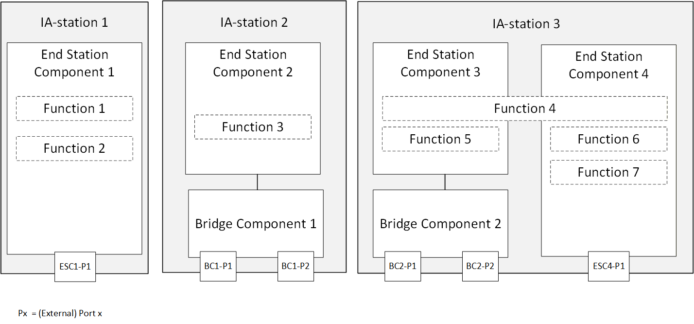
Figure 13 shows three examples of an IA-station. IA-station 1 comprises one End Station Component hosting two IA-station functions. IA-station 2 comprises one End Station Component hosting one IA-station function and one Bridge Component. IA-station 3 comprises a Bridge Component and two End Station Components hosting four IA-station functions. IA-station 3 shows that an IA-station function can span across multiple End Station Components.
6.4.2 IA-station requirements
An IA-station shall:
comprise at least one conformant End Station Component as defined in 6.3,
support topology discovery as defined in clause 7.3.
An IA-station may:
comprise one or more conformant Bridge Components as defined in 6.2,
support remote management as defined in clause 7.2,
support time synchronisation as defined in clause 7.4,
support middleware applications.
6.4.3 Default Priority to Traffic Class Mapping
Ethernet QoS mechanisms are defined to operate on PCP or traffic classes. For the latter, a mapping between the PCP value in the frame and the associated TC is needed. If the PCP to TC mapping has not been explicitly configured, an IA-station shall use the mapping defined in IEEE Std 802.1Q‑2022, Table 8-5.
6.5 UAFX Station definitions
6.5.1 Overview
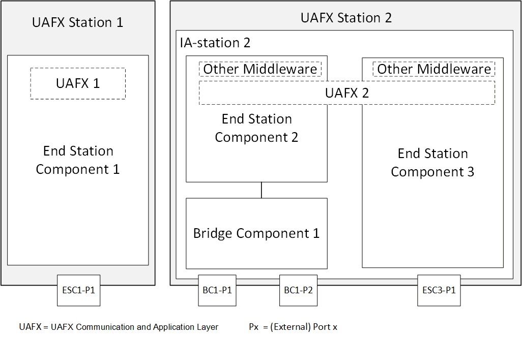
A UAFX Station is an IA-station (see 6.4) supporting the UAFX communication and application layer (see Figure 1). The UAFX communication and application layer is a logical component acting as a source of and/or destination for link layer data traffic. Thus, each UAFX Station incorporates at least one End Station Component where the UAFX communication and application layer can be located. Figure 14 shows that the UAFX communication and application layer can reside in one or multiple End Station Components.
6.5.2 UAFX Station requirements
A UAFX Station shall:
comprise a conformant IA-station,
support middleware modelling of network interfaces and QoS in the UAFX communication and application layer:
priority mapping configuration representation as defined in OPC 10000‑22, including the PriorityMappingTableType, MappingTables Folder, and the UsesPriorityMappingTable ReferenceType (see 6.5.4);
network interface representation as defined in OPC 10000-22, including the IetfBaseNetworkInterfaceType, the IIetfBaseNetworkInterfaceType and IIeeeBaseEthernetPortType Interfaces, and the NetworkInterfaces Folder (see );
C-VLAN configuration representation as defined in OPC 10000‑22, including the IVlanIdType Interface and the HasLowerLayerInterface ReferenceType (see ).
LLDP information representation as defined in OPC 10000‑22, including at least one instance of the LldpInformationType, and if the UAFX Station contains one or more Bridge Components, at least one instance of the RemoteSystemsData Component of the LldpInformationType.
6.5.3 Network interface representation and default configuration
Each physical network interface available to the UAFX Application shall be represented as an instance of IetfBaseNetworkInterfaceType in the NetworkInterfaces Folder defined in OPC 10000‑22. All VLAN interfaces attached to these physical network interfaces shall be represented as defined in OPC 10000‑22. A UAFX Station shall at least provide the default VLAN interface with the BrowseName as defined in Table 2 and a HasLowerLayerInterface reference to the respective physical network for each of these physical network interfaces. If the VlanId value has not been explicitly configured for this default VLAN interface, the VlanId shall assume the value defined in Table 2.
| BrowseName | VlanId (default) |
|---|---|
| <physical-interface>. | 100 |
6.5.4 Default PriorityMappingTable configuration
A UAFX Station shall provide a PriorityMappingTable with at least the default entries for MappingUri/QosCategory and PriorityLabel as defined in Table 3. If PCP and DSCP values have not been explicitly configured (i.e., to accommodate the needs of an existing network), PriorityValue_PCP and PriorityValue_DSCP shall assume the values defined in Table 3.
| MappingUri/QosCategory | PriorityLabel | PriorityValue_PCP (default) | PriorityValue_DSCP (default) |
|---|---|---|---|
| opc.qos.cat://priority | opc.qos.lbl://green | 4 | 46 |
Each physical network interface available to the UAFX Application, represented by an instance of IetfBaseNetworkInterfaceType in the NetworkInterfaces Folder, shall have a reference to an instance of PriorityMappingTableType that is exposed to OPC UA Clients, e.g., for adaptation during the system integration phase (see 5.6.4.4), as defined in OPC 10000‑22. The referenced PriorityMappingTableType instance shall include the AddPriorityMappingEntry and DeletePriorityMappingEntry Methods.