A UAFX Station is an IA-station (see 6.4) supporting the UAFX communication and application layer (see Figure 1). The UAFX communication and application layer is a logical component acting as a source of and/or destination for link layer data traffic. Thus, each UAFX Station incorporates at least one End Station Component where the UAFX communication and application layer can be located. Figure 14 shows that the UAFX communication and application layer can reside in one or multiple End Station Components.
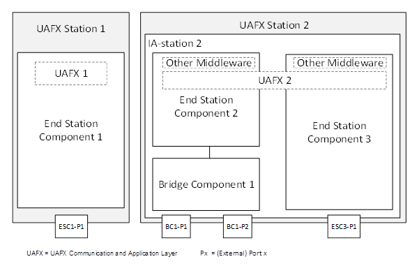
Figure 14 – UAFX Station examples
comprise a conformant IA-station,
support middleware modelling of network interfaces and QoS in the UAFX communication and application layer:
- priority mapping configuration representation as defined in OPC 1000022, including the PriorityMappingTableType, MappingTables Folder, and the UsesPriorityMappingTable ReferenceType (see 6.5.4);
- network interface representation as defined in OPC 10000-22, including the IetfBaseNetworkInterfaceType, the IIetfBaseNetworkInterfaceType and IIeeeBaseEthernetPortType Interfaces, and the NetworkInterfaces Folder (see 6.5.3);
- C-VLAN configuration representation as defined in OPC 1000022, including the IVlanIdType Interface and the HasLowerLayerInterface ReferenceType (see 6.5.3).
Each physical network interface available to the UAFX Application shall be represented as an instance of IetfBaseNetworkInterfaceType in the NetworkInterfaces Folder defined in OPC 1000022. All VLAN interfaces attached to these physical network interfaces shall be represented as defined in OPC 1000022. A UAFX Station shall at least provide the default VLAN interface with the BrowseName as defined in Table 2 and a HasLowerLayerInterface reference to the respective physical network for each of these physical network interfaces. If the VlanId value has not been explicitly configured for this default VLAN interface, the VlanId shall assume the value defined in Table 2.
Table 2 – Default VLAN interface values
|
BrowseName |
VlanId (default) |
|
<physical-interface>. |
100 |
Note: The BrowseName of the default VLAN interface in Table 2 starts with the physical interface that this VLAN interface is associated with and ends with the interface label “uafx-vlan” separated by a dot (“.”). “<physical-interface>” in Table 2 is a placeholder for the BrowseName (e.g., “eth0”) of the associated physical interface. This composition ensures the uniqueness of the default VLAN interface BrowseName in UAFX Stations with multiple network interfaces.
A UAFX Station shall provide a PriorityMappingTable with at least the default entries for MappingUri/QosCate gory and PriorityLabel as defined in Table 3. If PCP and DSCP values have not been explicitly configured (i.e., to accommodate the needs of an existing network), PriorityValue_PCP and PriorityValue_DSCP shall assume the values defined in Table 3.
Table 3 – Default PriorityMappingEntryType values
|
MappingUri/QosCategory |
PriorityLabel |
PriorityValue_PCP(default) |
PriorityValue_DSCP(default) |
|
opc.qos.cat://priority |
opc.qos.lbl://green |
4 |
46 |
Each physical network interface available to the UAFX Application represented by an instance of IetfBaseNetworkInterfaceType in the NetworkInterfaces Folder shall have a reference to an instance of PriorityMappingTableType that is exposed to OPC UA Clients, e.g., for adaptation during the system integration phase (see 5.6.4.4), as defined in OPC 1000022. The referenced PriorityMappingTableType instance shall include the AddPriorityMappingEntry and DeletePriorityMappingEntry Methods.