IA-stations can be a simple End Station Component (see 6.3) acting as the source or destination for industrial data traffic. IA-stations may also include a Bridge Component (see 6.2). More complex IA-stations incorporating several End Station Components and Bridge Components within one device can also be found in industrial automation (e.g., a Controller with multiple modules).
An IA-station can include one or more IA-station functions acting as the source or destination for data traffic. These functions, located in the End Station Components, include industrial automation applications, Remote Management, and other applications or services such as Time Synchronisation or Topology Discovery. IA-station functions can reside in a single or multiple End Station Components within a given IA-station.
Figure 13 shows three examples of an IA-station. IA-station 1 comprises one End Station Component hosting two IA-station functions. IA-station 2 comprises one End Station Component hosting one IA-station function and one Bridge Component. IA-station 3 comprises a Bridge Component and two End Station Components hosting four IA-station functions. IA-station 3 shows that an IA-station function can span across multiple End Station Components.
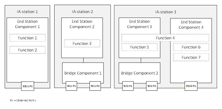
Figure 13 – IA-station examples
An IA-station shall:
comprise at least one conformant End Station Component as defined in 6.3,
support topology discovery as defined in clause 7.3.
An IA-station may:
comprise one or more conformant Bridge Components as defined in 6.2,
support remote management as defined in clause 7.2,
support time synchronisation as defined in clause 7.4,
support middleware applications.
Ethernet QoS mechanisms are defined to operate on PCP or traffic classes. For the latter, a mapping between the PCP value in the frame and the associated TC is needed. If the PCP to TC mapping has not been explicitly configured, an IA-station shall use the mapping defined in IEEE Std 802.1Q2022, Table 8-5.