Clause 6 describes the integration of this document into the OPC UA Information Models in 6.2 and the resulting Service interfaces in 6.3. Diagnostic services are described in 6.4.
Subclause 6.2 describes the identifiers, types and structure of the Objects and Methods that are used to implement the OPC UA mappers defined in this document. This implementation serves three purposes:
- support of the safe exchange of SPDUs at runtime
- online browsing, to identify SafetyConsumers and SafetyProviders, and to check their parameters for diagnostic purposes
- offline engineering: the Information Model of one controller can be exported in a standardized file on its engineering system, be imported in another engineering system, and finally deployed on another controller. This allows for a vendor-independent exchange of the communication interfaces of safety applications, e.g. for establishing connections between devices.
NOTE Neither online browsing nor offline engineering currently supports any features to detect errors. Hence, no guarantees with respect to functional safety are made. This means that online browsing can only be used for diagnostic purposes, and not for exchanging safety-relevant data. It is assumed that errors can occur during the transfer of the Information Model from one engineering system to another in the context of offline engineering. Therefore, the programmer of the safety application is responsible for the verification and validation of the safety application.
Consequently, all type values described in 6.2 are defined as read-only, i.e. they cannot be written by general OPC UA write commands.
[RQ6.1] Each Server shall have a singleton Folder called SafetyACSet with a fixed NodeID in the Namespace of this document. Because all SafetyProviders and SafetyConsumers on this Server contain a hierarchical Reference from this Object to themselves, it can be used to directly access all SafetyProviders and SafetyConsumers. SafetyACSet is intended for safety-related purposes only. It should not reference non-safety-related items.
See Table 3 for the definition of the SafetyACSet.
Table 3 – SafetyACSet definition
|
Attribute |
Value |
||
|
BrowseName |
SafetyACSet |
||
|
References |
NodeClass |
BrowseName |
Comment |
|
OrganizedBy by the Objects Folder defined in OPC 10000-5. |
|||
|
HasTypeDefinition |
ObjectType |
FolderType |
Entry point for all SafetyProviders and SafetyConsumers |
|
Conformance Units |
|||
|
SafetyACSet |
|||
[RQ6.2] In addition, a Server shall comprise one OPC UA Object derived from DataType SafetyProviderType for each SafetyProvider it implements, and one OPC UA Object derived from DataType SafetyConsumerType for each SafetyConsumer it implements. The corresponding Information Models shown in Figure 3 and Figure 4 shall be used.
A description of the graphical notation for the different types of Nodes and References (shown in Figure 3, Figure 4, and Figure 6) can be found in OPC UA 10000-3.
Figure 3 describes the SafetyProvider and the SafetyConsumer.
NOTE 1 This document assumes (atomic) consistent data exchange between OPC mappers of the two endpoints.
[RQ6.3a] For implementations supporting OPC UA Client/Server, the Call Service of the Method Service Set (see OPC UA 10000-4) shall be used. The Method ReadSafetyData has a set of input arguments that make up the RequestSPDU and a set of output arguments that make up the ResponseSPDU. The SafetyConsumer uses the OPC UA Client with the OPC UA Service Call.
[RQ6.3b] For implementations supporting OPC UA PubSub, the OPC UA Object SafetyPDUs with its Properties RequestSPDU and ResponseSPDU shall be used. RequestSPDU is published by the SafetyConsumer and subscribed by the SafetyProvider. ResponseSPDU is published by the SafetyProvider and subscribed by the SafetyConsumer.
NOTE 2 The terms “request” and “response” refer to the behaviour on the layer of this document. Within the PubSub context, both requests and responses are realized by repeatedly publishing and subscribing Messages, see Figure 14.
[RQ6.4] For diagnostic purposes, the SPDUs received and sent shall be accessible by calling the Method ReadSafetyDiagnostics.
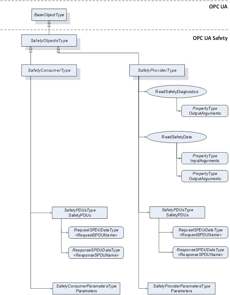
Figure 3 – Server Objects for OPC UA Safety
NOTE 3 For the input/output arguments of the Methods ReadSafetyData and ReadSafetyDiagnostics, see 6.2.2.3 and 6.2.2.4. For the parameters of the SafetyProvider and SafetyConsumer, see Figure 6, Table 12, and Table 13. For RequestSPDU and ResponseSPDU, see Table 7, Table 18, Table 20, and 7.2.1.
Figure 4 shows the instances of Server Objects for this document. The ObjectType for the SafetyProviderType contains Methods having outputs of the abstract DataType Structure. Each instance of a SafetyProvider requires its own copy of the Methods which contain the concrete DataTypes for OutSafetyData and OutNonSafetyData.
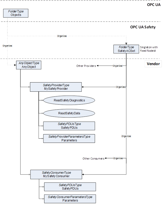
Figure 4 – Instances of Server Objects for this document
[RQ6.5] To reduce the number of variations and to alleviate validation testing, the following restrictions apply to instances of SafetyProviderType and SafetyConsumerType (or instances of DataTypes derived from SafetyProviderType or SafetyConsumerType):
The references shown in Figure 4 originating at SafetyProviderType or SafetyConsumerType and below shall be of ReferenceType HasComponent (and shall not be derived from ReferenceType HasComponent) for Object References or ReferenceType HasProperty (and shall not be derived from ReferenceType HasProperty) for Property References.
As BrowseNames (i.e. name and Namespace) are used to find Methods, the names of Objects and Properties shall be locally unique.
The DataType of both Properties and MethodArguments shall be used as specified, and no derived DataTypes shall be used (exception: OutSafetyData and OutNonSafetyData).
In IEC 62541, the order of Method arguments is relevant.
See Table 4 for the definition of the SafetyObjectsType.
Table 4 – SafetyObjectsType definition
|
Attribute |
Value |
||||
|
BrowseName |
SafetyObjectsType |
||||
|
IsAbstract |
True |
||||
|
References |
Node class |
BrowseName |
DataType |
TypeDefinition |
Modelling rule |
|
Subtype of BaseObjectType |
|||||
|
Conformance units |
|||||
|
SafetySupport |
|||||
See Table 5 for the definition of the SafetyProviderType.
Table 5 – SafetyProviderType definition
|
Attribute |
Value |
||||
|
BrowseName |
SafetyProviderType |
||||
|
IsAbstract |
False |
||||
|
References |
Node class |
BrowseName |
DataType |
TypeDefinition |
Modelling rule |
|
Subtype of SafetyObjectsType |
|||||
|
HasComponent |
Method |
ReadSafetyData |
|
|
Optional |
|
HasComponent |
Method |
ReadSafetyDiagnostics |
|
|
Optional |
|
HasComponent |
Object |
SafetyPDUs |
|
SafetyPDUsType |
Optional |
|
HasComponent |
Object |
Parameters |
|
SafetyProviderParametersType |
Mandatory |
|
Conformance units |
|||||
|
SafetyProviderParameters |
|||||
[RQ6.6] Instances of SafetyProviderType shall use non-abstract DataTypes for the arguments OutSafetyData and OutNonSafetyData.
See Table 6 for the definition of the SafetyConsumerType.
Table 6 – SafetyConsumerType definition
|
Attribute |
Value |
||||
|
BrowseName |
SafetyConsumerType |
||||
|
IsAbstract |
False |
||||
|
References |
Node class |
BrowseName |
DataType |
TypeDefinition |
Modelling rule |
|
Subtype of SafetyObjectsType |
|||||
|
HasComponent |
Object |
SafetyPDUs |
|
SafetyPDUsType |
Optional |
|
HasComponent |
Object |
Parameters |
|
SafetyConsumerParametersType |
Mandatory |
|
Conformance units |
|||||
|
SafetyConsumerParameters |
|||||
This Method is mandatory for the Facet SafetyProviderServerMapper. It is used to read SafetyData from the SafetyProvider. It is in the responsibility of the safety application that this Method is not concurrently called by multiple SafetyConsumers. Otherwise, the SafetyConsumer can receive invalid responses resulting in a safe reaction which can lead to either spurious trips or system unavailability, or both.
See Table 7 for Method ReadSafetyData’s arguments and Table 8 for its AdressSpace definition.
The Method argument OutSafetyData has an application-specific DataType derived from Structure. This DateType (including the DataTypeID) is expected to be the same in both the SafetyProvider and the SafetyConsumer. Otherwise, the SafetyConsumer will not accept the transferred data and switch to fail-safe substitute values instead (see state S16 in Table 34 as well as 7.2.3.2 and 7.2.3.5). The Method argument OutNonSafetyData has an application-specific DataType derived from Structure.
Signature
ReadSafetyData (
[in]UInt32InSafetyConsumerID,
[in]UInt32InMonitoringNumber,
[in]InFlagsTypeInFlags,
[out]StructureOutSafetyData,
[out]OutFlagsTypeOutFlags,
[out]UInt32OutSPDU_ID_1,
[out]UInt32OutSPDU_ID_2,
[out]UInt32OutSPDU_ID_3,
[out]UInt32OutSafetyConsumerID,
[out]UInt32OutMonitoringNumber,
[out]UInt32OutCRC,
[out]StructureOutNonSafetyData)
;
Table 7 – ReadSafetyData Method arguments
|
Argument |
Description |
|
|
InSafetyConsumerID |
“Safety Consumer Identifier”, see SafetyConsumerID in Table 23. |
|
|
InMonitoringNumber |
“MonitoringNumber of the RequestSPDU”, see 7.2.1.3 and MonitoringNumber in Table 23. |
|
|
InFlags |
“Octet with non-safety-related flags from SafetyConsumer”, see 6.2.3.1. |
|
|
OutSafetyData |
“SafetyData”, see 7.2.1.5. |
|
|
OutFlags |
“Octet with safety-related flags from SafetyProvider”, see 6.2.3.2. |
|
|
OutSPDU_ID_1 |
“Safety PDU Identifier Part1”, see 7.2.3.2. |
|
|
OutSPDU_ID_2 |
“Safety PDU Identifier Part2”, see 7.2.3.2. |
|
|
OutSPDU_ID_3 |
“Safety PDU Identifier Part3”, see 7.2.3.2. |
|
|
OutSafetyConsumerID |
“Safety Consumer Identifier”, see SafetyConsumerID in Table 23 and Table 26. |
|
|
OutMonitoringNumber |
MonitoringNumber of the ResponseSPDU, see 7.2.1.9, 7.2.3.1, and Figure 11. |
|
|
OutCRC |
CRC over the ResponseSPDU, see 7.2.3.6. |
|
|
OutNonSafetyData |
“Non-safe data” see 7.2.1.11. |
|
Table 8 – ReadSafetyData Method AddressSpace definition
|
Attribute |
Value |
||||
|
BrowseName |
ReadSafetyData |
||||
|
References |
NodeClass |
BrowseName |
DataType |
TypeDefinition |
ModellingRule |
|
HasProperty |
Variable |
InputArguments |
Argument[] |
PropertyType |
Mandatory |
|
HasProperty |
Variable |
OutputArguments |
Argument[] |
PropertyType |
Mandatory |
|
Conformance units |
|||||
|
ReadSafetyData |
|||||
This Method is mandatory for the Facet SafetyProviderServerMapper and optional for the Facet SafetyProviderPubSubMapper. It is provided for each SafetyProvider serving as a Diagnostic Interface, see 6.4.3.
See Table 9 for the arguments of Method ReadSafetyDiagnostics and Table 10 for its AddressSpace definition.
The Method arguments OutSafetyData and OutNonSafetyData are application-specific types derived from Structure.
Signature
ReadSafetyDiagnostics (
[out]UInt32InSafetyConsumerID,
[out]UInt32InMonitoringNumber,
[out]InFlagsTypeInFlags,
[out]StructureOutSafetyData,
[out]OutFlagsTypeOutFlags,
[out]UInt32OutSPDU_ID_1,
[out]UInt32OutSPDU_ID_2,
[out]UInt32OutSPDU_ID_3,
[out]UInt32OutSafetyConsumerID,
[out]UInt32OutMonitoringNumber,
[out]UInt32OutCRC,
[out]StructureOutNonSafetyData)
;
Table 9 – ReadSafetyDiagnostics Method arguments
|
Argument |
Description |
|
|
InSafetyConsumerID |
see Table 7 |
|
|
InMonitoringNumber |
see Table 7 |
|
|
InFlags |
see Table 7 |
|
|
OutSafetyData |
see Table 7 |
|
|
OutFlags |
see Table 7 |
|
|
OutSPDU_ID_1 |
see Table 7 |
|
|
OutSPDU_ID_2 |
see Table 7 |
|
|
OutSPDU_ID_3 |
see Table 7 |
|
|
OutSafetyConsumerID |
see Table 7 |
|
|
OutMonitoringNumber |
see Table 7 |
|
|
OutCRC |
see Table 7 |
|
|
OutNonSafetyData |
see Table 7 |
|
Table 10 – ReadSafetyDiagnostics Method AddressSpace definition
|
Attribute |
Value |
||||
|
BrowseName |
ReadSafetyDiagnostics |
||||
|
References |
NodeClass |
BrowseName |
DataType |
TypeDefinition |
ModellingRule |
|
HasProperty |
Variable |
OutputArguments |
Argument[] |
PropertyType |
Mandatory |
|
Conformance units |
|||||
|
ReadSafetyDiagnostics |
|||||
This Object is mandatory for the Facet SafetyProviderPubSubMapper and the Facet SafetyConsumerPubSubMapper It is used by the SafetyProvider to subscribe to the RequestSPDU and to publish the ResponseSPDU. The DataType of RequestSPDU is structured in the same way as the input arguments of ReadSafetyData. The DataType of ResponseSPDU is structured in the same way as the output arguments of ReadSafetyData.
See Table 11 for the definition of the SafetyPDUsType.
Both variables in the SafetyPDUsType have a counterpart within the Information Model of the SafetyConsumer. The SafetyConsumer publishes the RequestSPDU and subscribes to the ResponseSPDU.
Table 11 – SafetyPDUsType definition
|
Attribute |
Value |
|||||
|
BrowseName |
SafetyPDUsType |
|||||
|
IsAbstract |
False |
|||||
|
References |
Node class |
BrowseName |
DataType |
TypeDefinition |
Modelling rule |
|
|
Subtype of BaseObjectType |
||||||
|
HasComponent |
Variable |
<RequestSPDU> |
RequestSPDUDataType |
BaseDataVariableType |
Mandatory Placeholder |
|
|
HasComponent |
Variable |
<ResponseSPDU> |
ResponseSPDUDataType |
BaseDataVariableType |
Mandatory Placeholder |
|
|
Conformance units |
||||||
|
SafetyPDUs |
||||||
The Object SafetyPDUs shall contain exactly one Reference to a Variable of DataType RequestSPDUDataType and exactly one Reference to a Variable of a subtype of DataType ResponseSPDUDataType.
For example, Figure 5 shows a distributed safety application with four SafetyAutomationComponents. It is assumed that SafetyAutomationComponent 1 sends a value to the other three SafetyAutomationComponents using three SafetyProviders, each comprising a pair of SPDUs. For each recipient, there is an individual pair of SPDUs.
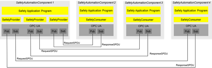
Figure 5 – Safety multicast with three recipients using IEC 62541 PubSub
Figure 6 shows the safety parameters for the SafetyProvider and the SafetyConsumer.
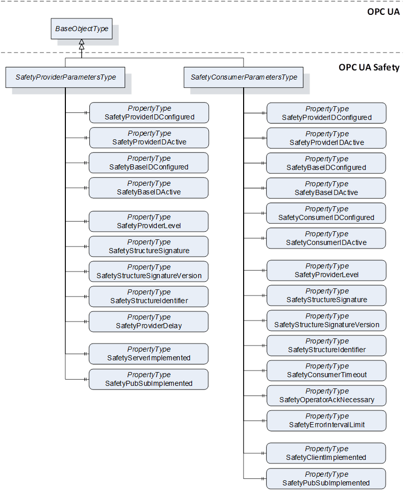
Figure 6 – Safety parameters for the SafetyProvider and the SafetyConsumer
Table 12 shows the definition for the SafetyProviderParametersType. Refer to 6.3.3.3 for more details on the Safety Parameter Interface (SPI) of the SafetyProvider.
Table 12 – SafetyProviderParametersType definition
|
Attribute |
Value |
||||
|
BrowseName |
SafetyProviderParametersType |
||||
|
IsAbstract |
False |
||||
|
References |
Node class |
BrowseName |
DataType |
TypeDefinition |
Modelling rule |
|
Subtype of BaseObjectType |
|||||
|
HasProperty |
Variable |
SafetyProviderIDConfigured |
UInt32 |
PropertyType |
Mandatory |
|
HasProperty |
Variable |
SafetyProviderIDActive |
UInt32 |
PropertyType |
Mandatory |
|
HasProperty |
Variable |
SafetyBaseIDConfigured |
Guid |
PropertyType |
Mandatory |
|
HasProperty |
Variable |
SafetyBaseIDActive |
Guid |
PropertyType |
Mandatory |
|
HasProperty |
Variable |
SafetyProviderLevel |
Byte |
PropertyType |
Mandatory |
|
HasProperty |
Variable |
SafetyStructureSignature |
UInt32 |
PropertyType |
Mandatory |
|
HasProperty |
Variable |
SafetyStructureSignatureVersion |
UInt16 |
PropertyType |
Mandatory |
|
HasProperty |
Variable |
SafetyStructureIdentifier |
String |
PropertyType |
Mandatory |
|
HasProperty |
Variable |
SafetyProviderDelay |
UInt32 |
PropertyType |
Mandatory |
|
HasProperty |
Variable |
SafetyServerImplemented |
Boolean |
PropertyType |
Mandatory |
|
HasProperty |
Variable |
SafetyPubSubImplemented |
Boolean |
PropertyType |
Mandatory |
|
Conformance units |
|||||
|
SafetyProviderParameters |
|||||
The parameters for SafetyProviderID and SafetyBaseID exist in pairs for “Configured” and “Active” states:
- SafetyProviderIDConfigured and SafetyProviderIDActive,
- SafetyBaseIDConfigured and SafetyBaseIDActive.
The “[...]Configured” parameters shall always deliver the values as configured via the SPI. The “[...]Active” parameters shall deliver:
- the corresponding “[...]Configured” values if the system is still offline;
- the values which have been set during runtime via the SAPI parameters (SafetyProviderID, SafetyBaseID);
- the corresponding “[...]Configured” values if the active values have been set to zero via the SAPI parameters (SafetyProviderID, SafetyBaseID).
The Property SafetyBaseIDConfigured is shared for all SafetyProviders with the same SafetyBaseIDConfigured value. If multiple instances of SafetyObjectsType are running on the same Node, it is a viable optimization that a Property SafetyBaseIDConfigured is referenced by either multiple SafetyProviders or SafetyConsumers, or both.
For releases up to Release 2.0 of the document, the value for the SafetyStructureSignatureVersion shall be 0x0001 (see RQ7.21 in 7.2.3.5).
Table 13 shows the definition of the SafetyConsumerParametersType. The Properties SafetyStructureIdentifier and SafetyStructureSignatureVersion are optional, because SafetyStructureSignature is typically calculated in an offline engineering tool. For small devices, it could be beneficial to only upload the SafetyStructureSignature to the device, but not SafetyStructureIdentifier and SafetyStructureSignatureVersion in order to save either bandwidth or memory, or both. Refer to 6.3.4.4 for more details on the Safety Parameter Interface (SPI) of the SafetyConsumer.
Table 13 – SafetyConsumerParametersType definition
|
Attribute |
Value |
||||
|
BrowseName |
SafetyConsumerParametersType |
||||
|
IsAbstract |
False |
||||
|
References |
Node class |
BrowseName |
DataType |
TypeDefinition |
Modelling rule |
|
Subtype of BaseObjectType |
|||||
|
HasProperty |
Variable |
SafetyProviderIDConfigured |
UInt32 |
PropertyType |
Mandatory |
|
HasProperty |
Variable |
SafetyProviderIDActive |
UInt32 |
PropertyType |
Mandatory |
|
HasProperty |
Variable |
SafetyBaseIDConfigured |
Guid |
PropertyType |
Mandatory |
|
HasProperty |
Variable |
SafetyBaseIDActive |
Guid |
PropertyType |
Mandatory |
|
HasProperty |
Variable |
SafetyConsumerIDConfigured |
UInt32 |
PropertyType |
Mandatory |
|
HasProperty |
Variable |
SafetyConsumerIDActive |
UInt32 |
PropertyType |
Mandatory |
|
HasProperty |
Variable |
SafetyProviderLevel |
Byte |
PropertyType |
Mandatory |
|
HasProperty |
Variable |
SafetyStructureSignature |
UInt32 |
PropertyType |
Mandatory |
|
HasProperty |
Variable |
SafetyStructureSignatureVersion |
UInt16 |
PropertyType |
Optional |
|
HasProperty |
Variable |
SafetyStructureIdentifier |
String |
PropertyType |
Optional |
|
HasProperty |
Variable |
SafetyConsumerTimeout |
UInt32 |
PropertyType |
Mandatory |
|
HasProperty |
Variable |
SafetyOperatorAckNecessary |
Boolean |
PropertyType |
Mandatory |
|
HasProperty |
Variable |
SafetyErrorIntervalLimit |
UInt16 |
PropertyType |
Mandatory |
|
HasProperty |
Variable |
SafetyClientImplemented |
Boolean |
PropertyType |
Mandatory |
|
HasProperty |
Variable |
SafetyPubSubImplemented |
Boolean |
PropertyType |
Mandatory |
|
Conformance units |
|||||
|
SafetyConsumerParameters |
|||||
The parameters for SafetyProviderID, SafetyBaseID and SafetyConsumerID exist in pairs for “Configured” and “Active” states: SafetyProviderIDConfigured and SafetyProviderIDActive, SafetyBaseIDConfigured and SafetyBaseIDActive, and SafetyConsumerIDConfigured and SafetyConsumerIDActive.
The “[...]Configured” parameters shall always deliver the values as configured via the SPI. The “[...]Active” parameters shall deliver:
- the corresponding “[...]Configured” values if the system is still offline;
- the values which have been set during runtime via the SAPI parameters (SafetyProviderID, SafetyBaseID, SafetyConsumerID);
- the corresponding “[...]Configured” values if the active values have been set to zero via the SAPI parameters (SafetyProviderID, SafetyBaseID, SafetyConsumerID).
The InFlagsType a subtype of the Byte DataType with the OptionSetValues Property defined. The InFlagsType is formally defined in Table 14.
CommunicationError can be used as a trigger, e.g. for a communication analysis tool. It is not forwarded to the safety application by the SafetyProvider. If CommunicationError is necessary in the safety application, bidirectional communication can be implemented and the value of CommunicationError can be put into the user data.
|
Value |
Bit no. |
Description |
|
CommunicationError |
0 |
0: No error 1: An error was detected in the previous ResponseSPDU. |
|
OperatorAckRequested |
1 |
Used to inform the SafetyProvider that operator acknowledgment is requested. |
|
FSV_Activated |
2 |
Used for conformance test of SafetyConsumer.SAPI.FSV_Activated. |
Bits 3 to 7 are reserved for future use and shall be set to zero by the SafetyConsumer. They shall not be evaluated by the SafetyProvider.
The InFlagsType representation in the AddressSpace is defined in Table 15.
Table 15 – InFlagsType dDefinition
|
Attribute |
Value |
|||||
|
BrowseName |
InFlagsType |
|||||
|
IsAbstract |
False |
|||||
|
References |
NodeClass |
BrowseName |
DataType |
TypeDefinition |
Other |
|
|
0:HasProperty |
Variable |
0:OptionSetValues |
0:LocalizedText [] |
0:PropertyType |
|
|
|
Conformance units |
||||||
|
SafetySupport |
||||||
The OutFlagsType is a subtype of the Byte DataType with the OptionSetValues Property defined. The OutFlagsType is formally defined in Table 16.
Table 16 – OutFlagsType values
|
Value |
Bit no. |
Description |
|
OperatorAckProvider |
0 |
Operator acknowledgment at the provider, hereby forwarded to the SafetyConsumer, see OperatorAckProvider in the SAPI of the SafetyProvider, 6.3.3.2. |
|
ActivateFSV |
1 |
Activation of fail-safe values by the safety application at the SafetyProvider, hereby forwarded to the SafetyConsumer, see ActivateFSV in the SAPI of the SafetyProvider, 6.3.3.2. |
|
TestModeActivated |
2 |
Enabling and disabling of test mode in the SafetyProvider, hereby forwarded to the SafetyConsumer, see EnableTestMode in the SAPI of the SafetyProvider, 6.3.3.2. |
Bits 3 to 7 are reserved for future use and shall be set to zero by the SafetyProvider. They shall not be evaluated by the SafetyConsumer.
The OutFlagsType representation in the AddressSpace is defined in Table 17.
Table 17 – OutFlagsType dDefinition
|
Attribute |
Value |
|||||
|
BrowseName |
OutFlagsType |
|||||
|
IsAbstract |
False |
|||||
|
References |
NodeClass |
BrowseName |
DataType |
TypeDefinition |
Other |
|
|
Subtype of the Byte DataType defined in OPC 10000-3 |
||||||
|
0:HasProperty |
Variable |
0:OptionSetValues |
0:LocalizedText [] |
0:PropertyType |
|
|
|
Conformance units |
||||||
|
SafetySupport |
||||||
Table 18 shows the definition of the RequestSPDUDataType. The Prefix “In” is interpreted from the SafetyProvider’s point of view and is used in a consistent manner to the parameters of the Method ReadSafetyData (see 6.2.2.3).
Table 18 – RequestSPDUDataType structure
|
Name |
Type |
Description |
|
RequestSPDUDataType |
structure |
|
|
InSafetyConsumerID |
UInt32 |
|
|
InMonitoringNumber |
UInt32 |
|
|
InFlags |
InFlagsType |
The representation in the AddressSpace of the RequestSPDUDataType is defined in Table 19.
Table 19 – RequestSPDUDataType definition
|
Attributes |
Value |
||||
|
BrowseName |
RequestSPDUDataType |
||||
|
IsAbstract |
False |
||||
|
References |
NodeClass |
BrowseName |
DataType |
TypeDefinition |
ModellingRule |
|
Subtype of Structure defined in OPC 10000-3. |
|||||
|
Conformance units |
|||||
|
SafetyPDUs |
|||||
Table 20 shows the ResponseSPDUDataType Structure. The Prefix “Out” is interpreted from the SafetyProvider’s point of view and is used in a consistent manner to the parameters of the Method ReadSafetyData (see 6.2.2.3).
Table 20 – ResponseSPDUDataType structure
|
Name |
Type |
Description |
|
ResponseSPDUDataType |
structure |
|
|
OutFlags |
OutFlagsType |
|
|
OutSPDU_ID_1 |
UInt32 |
|
|
OutSPDU_ID_2 |
UInt32 |
|
|
OutSPDU_ID_3 |
UInt32 |
|
|
OutSafetyConsumerID |
UInt32 |
|
|
OutMonitoringNumber |
UInt32 |
|
|
OutCRC |
UInt32 |
[RQ6.7] To define the concrete DataType for the ResponseSPDU (which specifies the concrete DataTypes for SafetyData and NonSafetyData, respectively), proceed as follows: (1) Derive a concrete DataType from the abstract ResponseSPDUDataType. (2) In doing so, add the following fields to the Structure in the given order: (a) First, field OutSafetyData with the concrete Structure DataType for the SafetyData (see 7.2.1.5). (b) Second, field NonSafetyData with the concrete Structure DataType for the NonSafetyData (or a placeholder DataType, see requirement RQ6.8).
[RQ6.8] To avoid possible problems with empty Structures, the dummy Structure NonSafetyDataPlaceholder shall be used as DataType for OutNonSafetyData when no NonSafetyData is used. The DataType Node defining this Structure has a fixed NodeID and contains a single Boolean.
The representation in the AddressSpace of the ResponseSPDUDataType is defined in Table 21.
Table 21 – ResponseSPDUDataType definition
|
Attributes |
Value |
||||
|
BrowseName |
ResponseSPDUDataType |
||||
|
IsAbstract |
True |
||||
|
References |
NodeClass |
BrowseName |
DataType |
TypeDefinition |
ModellingRule |
|
Subtype of Structure defined in OPC 10000-3 |
|||||
|
Conformance units |
|||||
|
SafetyPDUs |
|||||
Table 22 shows the definition of the NonSafetyDataPlaceholderDataType. The receiver shall not evaluate the value of ‘dummy’.
Table 22 – NonSafetyDataPlaceholderDataType structure
|
Name |
Type |
Description |
|
NonSafetyDataPlaceholderDataType |
Structure |
|
|
Dummy |
Boolean |
Dummy Variable to avoid empty structures. |
Future versions may use different identifiers (such as ReadSafetyDataV2 for the Method when using Client/Server communication or RequestSPDUV2DataType and ResponseSPDUV2DataType for the SPDU DataTypes when using PubSub communication), allowing a SafetyProvider to implement multiple versions of this document at the same time. Hence, the same SafetyProvider can be accessed by SafetyConsumers of different versions.
This document supports sending of the Built-in and Simple DataTypes specified in OPC UA (see OPC 10000-3 and OPC 10000-6) within SafetyData. The supported DataTypes are vendor-specific.
[RQ6.9] Only scalar DataTypes shall be used. Arrays are currently not supported by this document.
The supported maximum length of the SafetyData is vendor-specific but still limited to 1 500 octets. Typical values for the maximum length include 1 octet, 16 octets, 64 octets, 256 octets, 1 024 octets, and 1 500 octets.
[RQ6.10] For controller-like devices, the supported DataTypes and the maximum length of the SafetyData shall be listed in the user manual.
[RQ6.11] For the DataType Boolean, the value 0x01 shall be used for ‘true’ and the value 0x00 shall be used for ‘false’.
It is recommended to send multiple Booleans in separate variables. However, in small devices, it can be necessary to combine a set of 8 Booleans in one Variable for performance reasons. In this case, the DataType Byte can be used.
This document uses the OPC UA services for connection establishment, it poses no additional requirement to these services.
This version of the document describes configuration only at engineering time. This means that the parameters defined in the SPI (see 6.3.3.3 and 6.3.4.4) are read-only via the interface described in this document. Changing of parameters is expected to be done in a safety-related way, using the respective tools and interfaces provided by the vendor. Future versions of this document may specify a vendor-independent interface for configuration.
Figure 7 gives an overview of the safety communication layer and its interfaces. It thereby also shows the scope of this document. The main function of the layer services is the state machine which handles the protocol. The state machines interact with the following interfaces:
- The Safety Application Program Interface (SAPI) is accessed by the safety application for exchanging SafetyData during runtime.
- The Safety Parameter Interface (SPI) is accessed during commissioning for setting safety parameters such as IDs or the timeout value in the SafetyConsumer.
- The non-safety related Diagnostic Interface (DI) can be accessed at runtime for troubleshooting the safety communication.
The OPC UA Platform Interface (OPC UA PI) connects the SCL to the non-safe OPC UA stack and is used during runtime.
The interfaces (SAPI, SPI, DI and OPC UA PI) described in 6.3 are abstract and informative. They represent logical data inputs and outputs to this layer that are necessary for the proper operation of the state machine. No normative, concrete mappings are specified. The concrete implementations are vendor-specific and do no necessarily exactly match the abstract interfaces described in this document.
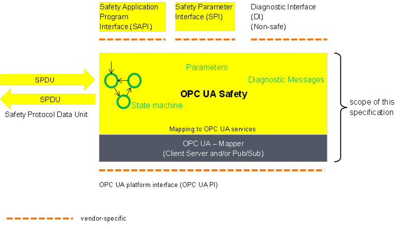
Figure 7 – Safety communication layer overview
The state machines of this document are independent from the actual OPC UA services used for data transmission. This is accomplished by introducing a so-called OPC UA Mapper, serving as an interface between the safety communication layer and the OPC UA stack.
The mapper can either make use of OPC UA Client/Server and remote Method invocation or the publishing of and subscribing to remote Variables as defined in OPC 10000-14. The requirements on the implementation of the mapper are implicitly given in 6.2.
Figure 8 shows an overview of the SafetyProvider interfaces. The SAPI is specified in 6.3.3.2, the SPI is specified in 6.3.3.3.
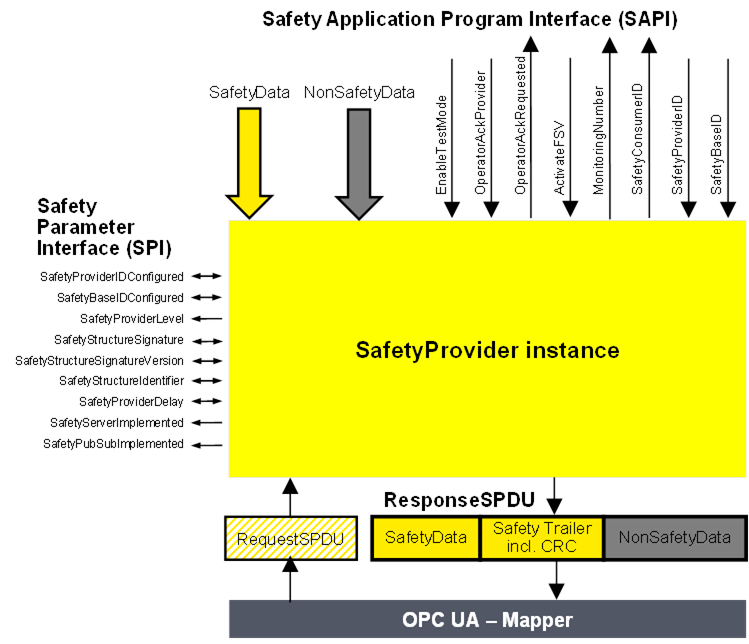
Figure 8 – SafetyProvider interfaces
[RQ6.12] The SAPI of the SafetyProvider represents the safety communication layer services of the SafetyProvider. Table 23 lists all inputs and outputs of the SAPI of the SafetyProvider. Each SafetyProvider shall implement the SAPI as shown in Table 23, however, the details are vendor-specific.
Table 23 – SAPI of the SafetyProvider
|
SAPI Term |
Type |
I/O |
Definition |
|
SafetyData |
Structure |
I |
This input is used to accept the user data which is then transmitted as SafetyData in the SPDU. NOTE Whenever a new MNR is received from a SafetyConsumer, the state machine of the SafetyProvider will read a new value of the SafetyData from its corresponding Safety Application and use it until the next MNR is received. If no valid user data is available at the Safety Application, ActivateFSV can be set to “1” by the Safety Application. |
|
NonSafetyData |
Structure |
I |
Used to consistently transmit NonSafetyData values (e.g. diagnostic information) together with safe data, see 7.2.1.11 |
|
EnableTestMode |
Boolean |
I |
By setting this input to “1” the remote SafetyConsumer is informed (by Bit 2 in ResponseSPDU.Flags, see 6.2.3.2) that the SafetyData are test data, and are not to be used for safety-related decisions. NOTE This document is intended for implementation in safety devices exclusively, see requirement RQ4.1. |
|
OperatorAckProvider |
Boolean |
I |
This input is used to implement an operator acknowledgment on the SafetyProvider side. The value will be forwarded to the SafetyConsumer, where it can be used to trigger a return from fail-safe substitute values (FSV) to actual process values (PV), see B.3.4. |
|
OperatorAckRequested |
Boolean |
O |
Indicates that an operator acknowledge is requested by the SafetyConsumer. This flag is received within the RequestSPDU. |
|
ActivateFSV(Fail-safe substitutevalues) |
Boolean |
I |
By setting this input to “1” the SafetyConsumer is instructed (via Bit 1 in ResponseSPDU.Flags, see 6.2.3.2) to deliver FSV instead of PV to the safety application program. NOTE If the replacement of process values by FSV is to be controllable in a more fine-grained way, this can be realized by using qualifiers within the SafetyData, see 6.3.6. |
|
SafetyConsumerID |
UInt32 |
O |
This output yields the ConsumerID used in the last access to this SafetyProvider by a SafetyConsumer (see 6.2.2.3). Since all safety-related checks are executed by an implementation of this document, the safety application is not required to check this SafetyConsumerID. |
|
MonitoringNumber |
UInt32 |
O |
This output yields the MonitoringNumber (MNR). It is updated whenever a new request comes in from the SafetyConsumer. Since all safety-related checks are executed by an implementation of this document, the safety application is not required to check this MonitoringNumber. |
|
SafetyProviderID |
UInt32 |
I |
For dynamic systems, this input can be set to a non-zero value. In this case, the SafetyProvider uses this value instead of the value from the SPI parameter SafetyProviderIDConfigured. If the value is changed to “0”, the value of parameter SafetyProviderIDConfigured from the SPI will be used (again). See Figure 8, 3.1.2.15, and 9.1.1. For static systems, this input is usually always kept at value “0”. |
|
SafetyBaseID |
Guid |
I |
For dynamic systems, this input can be set to a non-zero value. In this case, the SafetyProvider uses this value instead of the value of the SPI parameter SafetyBaseIDConfigured. If the value is changed to “0”, the value of parameter SafetyBaseIDConfigured from the SPI will be used (again). See Figure 8, 3.1.2.14, and 9.1.1. For static systems, this input is usually always kept at value “0”. |
[RQ6.13a] Each SafetyProvider shall implement the parameters and constants [RQ6.13b] as shown in Table 24. The parameters (R/W in column “Access”) can be set via the SPI, whereas the constants (R in column “Access”) are read-only. The mechanisms for setting the parameters are vendor-specific. The attempt of setting a parameter to a value outside its range, or of the setting of a read-only parameter, shall not become effective, and a diagnostic message should be shown when appropriate. The values of the constants depend on the way the SafetyProvider is implemented. They never change and are therefore not writable via any of the interfaces.
Table 24 – SPI of the SafetyProvider
|
Identifier |
Type |
Range |
Initial value (before configuration) |
Access |
Note |
|
SafetyProviderIDConfigured |
UInt32 |
0x0 to 0xFFFFFFFF |
0x0 |
R/W |
SafetyProviderID of the SafetyProvider that is normally used, see 3.1.2.15 and 9.1.1. For dynamic systems, the safety application program can overwrite this ID by providing a non-zero value at the input SafetyProviderID of the SafetyProvider’s SAPI. This runtime value can be queried using the SafetyProviderIDActive parameter. See 6.2.2.6 for details on configured and active values. NOTE If both the values provided at the SPI and the SAPI are 0x0, this means that the SafetyProvider is not properly configured. SafetyConsumers will never try to communicate with SafetyProviders having a SafetyProviderID of 0x0, see Transitions T13/T27 in Table 35 and the macro <ParametersOK?> in Table 33. |
|
SafetyBaseIDConfigured |
Guid |
Any value which can be represented with sixteen octets |
All sixteenoctets are 0x00 |
R/W |
SafetyBaseID of the SafetyProvider that is normally used, see 3.1.2.14 and 9.1.1. For dynamic systems, the safety application program can overwrite this ID by providing a non-zero value at the input SafetyBaseID of the SafetyProvider’s SAPI. This runtime value can be queried using the SafetyBaseIDActive parameter. See 6.2.2.6 for details on configured and active values. NOTE If both the values provided at the SPI and the SAPI are 0x0, this means that the SafetyProvider is not properly configured. SafetyConsumers will never try to communicate with SafetyProviders having a SafetyBaseID of 0x0, see Transitions T13/T27 in Table 35 and the macro <ParametersOK?> in Table 33. |
|
SafetyProviderLevel |
Byte |
0x01 to 0x04 |
n.a. |
R |
The SIL the SafetyProvider implementation (hardware and software) is capable of, see Figure 9. NOTE 1 It is independent from the generation of the SafetyData at SAPI. NOTE 2 The SafetyProviderLevel is used to distinguish devices of a different SIL. As a result, SPDUs coming from a device with a low SIL will never be accepted when a SafetyConsumer is parameterized to implement a safety function with a high SIL. |
|
SafetyStructureSignature |
UInt32 |
0x0 to 0xFFFFFFFF |
0x0 |
R/W |
Signature of the SafetyData structure, for calculation see 7.2.3.5. NOTE “0” would not be a valid signature and thus indicates a SafetyProvider which is not properly configured. SafetyConsumers will never try to communicate with SafetyProviders having a SafetyStructureSignature of 0x0, see Transitions T13/T27 in Table 35 and the macro <ParametersOK?> in Table 33. |
|
SafetyStructureSignatureVersion |
UInt16 |
0x1 |
0x1 |
R/W |
Version used to calculate SafetyStructureSignature, see 7.2.3.5 |
|
SafetyStructureIdentifier |
String |
all strings |
“” (the empty string) |
R/W |
Identifier describing the DataType of the SafetyData, see 7.2.3.5. |
|
SafetyProviderDelay |
UInt32 |
0x0 to 0xFFFFFFFF |
0x0 |
R/W |
In microseconds (µs). It can be set during the engineering phase of the SafetyProvider or set during online configuration as well. SafetyProviderDelay is the maximum time at the SafetyProvider from receiving the RequestSPDU to start the transmission of ResponseSPDU, see 8.1. The parameter SafetyProviderDelay has no influence on the functional behaviour of the SafetyProvider. Therefore, it is not necessary for this value to be generated in a safety-related way. However, it will be provided in the OPC UA Information Model of a SafetyProvider to inform about its worst-case delay time. The value can be used during commissioning to check whether the timing behaviour of the SafetyProvider is suitable to fulfill the watchdog delay of the corresponding SafetyConsumer. |
|
SafetyServerImplemented |
Boolean |
0x0 or 0x1 |
n.a. |
R |
This read-only parameter indicates whether the SafetyProvider has implemented the Server part of OPC UA Client/Server communication (see 5.4): 1: Server for OPC UA Client/Server communication is implemented. 0: Server for OPC UA Client/Server communication is not implemented. The corresponding Facets are SafetyProviderServer and SafetyProviderServerMapper. |
|
SafetyPubSubImplemented |
Boolean |
0x0 or 0x1 |
n.a. |
R |
This read-only parameter indicates whether the SafetyProvider has implemented the necessary publishers and subscribers for OPC UA PubSub communication (see 5.4): 1: OPC UA PubSub communication is implemented. 0: OPC UA PubSub communication is not implemented. The corresponding Facets are SafetyProviderPubSub and SafetyProviderPubSubMapper. |
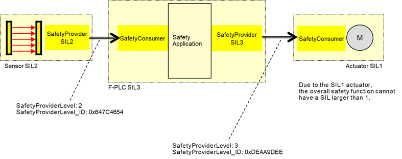
Figure 9 – Example combinations of SIL capabilities
The constant SafetyProviderLevel determines the value that is used for SafetyProviderLevel_ID when calculating the SPDU_ID, see 7.2.3.4.
NOTE SafetyProviderLevel is defined as the SIL the SafetyProvider implementation (hardware and software) is capable of, not to be confused with the SIL of the implemented safety function. For instance, Figure 9 shows a safety function which is implemented using a SIL 2-capable sensor, a SIL 3-capable PLC, and a SIL 1-capable actuator. The overall SIL of the safety function is considered to be SIL 1. Nevertheless, the SafetyProvider implemented on the sensor will use the constant value “2” as SafetyProviderLevel, whereas the SafetyProvider implemented on the PLC will use the constant value “3” as SafetyProviderLevel.
It is necessary for the respective SafetyConsumers (on the PLC and the actuator) to know the SafetyProviderLevel of their SafetyProviders in order to check the SPDU_ID (see 7.2.3.2).
Figure 10 shows an overview of the SafetyConsumer interfaces. The Safety Application Program Interface (SAPI) is specified in 6.3.4.2, the Safety Parameter Interface (SPI) is specified in 6.3.4.4.
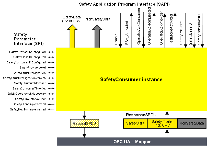
Figure 10 – SafetyConsumer interfaces
The SAPI of the SafetyConsumer represents the safety communication layer services of the SafetyConsumer. Table 25 lists all inputs and outputs of the SAPI of the SafetyConsumer.
[RQ6.14] Each SafetyConsumer shall implement the SAPI as shown in Table 25, however, the details are vendor-specific.
Table 25 – SAPI of the SafetyConsumer
|
SAPI Term |
Type |
I/O |
Definition |
|
SafetyData |
Structure |
O |
This output either delivers the process values received from the SafetyProvider in the SPDU field SafetyData, or FSV. |
|
NonSafetyData |
Structure |
O |
This output delivers the non-safety process values (e.g. diagnostic information) which were sent together with safe data, see 7.2.1.11 |
|
Enable |
Boolean |
I |
By changing this input to “0” the SafetyConsumer will change each and every Variable of the SafetyData to “0”1 and stop sending requests to the SafetyProvider. When changing Enable to “1” the SafetyConsumer will restart safe communication. The variable can be used to delay the start of the safety communication according to this document, after power on until “OPC UA connection ready” is set.The delay time is not monitored while enable is set to “0”. |
|
FSV_Activated |
Boolean |
O |
This output indicates via “1” that on the output SafetyData FSV (all binary “0”) are provided1. NOTE A ResponseSPDU which is checked with an error results in FSV_Activated being set to “1”, see T24 in Table 35. There could be other reasons. |
|
OperatorAckConsumer |
Boolean |
I |
For motivation, see 6.3.4.3. After an indication of OperatorAckRequested this input can be used to signal an operator acknowledgment. By changing this input from “0” to “1” (rising edge) the SafetyConsumer is instructed to switch SafetyData from FSV to PV. OperatorAckConsumer is processed only if this rising edge arrives after OperatorAckRequested was set to “1”, see Figure 19. If a rising edge of OperatorAckConsumer arrives before OperatorAckRequested becomes 1, this rising edge is ignored. |
|
OperatorAckRequested |
Boolean |
O |
This output indicates the request for operator acknowledgment. The bit is set to “1” by the SafetyConsumer, when three conditions are met: 1)Too many communication errors were detected in the past, so the SafetyConsumer decided to switch to fail-safe substitute values. 2)Currently, no communication errors occur, and hence operator acknowledgment is possible. 3)Operator acknowledgment (rising edge at input OperatorAckConsumer) has not yet occurred. The bit is reset to “0” when a rising edge at OperatorAckConsumer is detected. |
|
OperatorAckProvider |
Boolean |
O |
This output indicates that an operator acknowledgment has taken place on the SafetyProvider. If operator acknowledgment at the SafetyProvider should be allowed, this output is connected to OperatorAckConsumer, see B.3.4 and B.3.5. NOTE If the ResponseSPDU is checked with error, this output remains at its last value, see T24 in Table 35. |
|
TestModeActivated |
Boolean |
O |
The safety application program is expected to evaluate this output for determining whether the communication partner is in test mode or not. A value of “1” indicates that the communication partner (source of data) is in test mode, e.g. during commissioning. Data coming from a device in test mode may be used for testing but is not intended to be used to control safety-critical processes. A value of “0” represents the “normal” safety-related mode. The test mode enables the programmer and commissioner to validate the safety application using test data. NOTE If the ResponseSPDU check results in an error and the ErrorIntervalTimer (see 6.3.4.4) is also not expired, TestModeActivated is reset, see state S17_Error in Table 34. |
|
SafetyProviderID |
UInt32 |
I |
For dynamic systems, this input can be set to a non-zero value. In this case, the SafetyConsumer uses this variable instead of the SPI parameter SafetyProviderIDConfigured. This input is only read in the first cycle, or when a rising edge occurs at the input Enable. See also Table 26. If it is changed to “0”, the value of SPI parameter SafetyProviderIDConfigured will be used (again). For static systems, this input is usually always kept at value “0”. |
|
SafetyBaseID |
Guid |
I |
For dynamic systems, this input can be set to a non-zero value. In this case, the SafetyConsumer uses this variable instead of the SPI parameter SafetyBaseIDConfigured. This input is only read in the first cycle, or when a rising edge occurs at the input Enable. See also Table 26. If it is changed to “0”, the SPI parameter SafetyBaseIDConfigured will become activated. For static systems, this input is usually always kept at value “0”. |
|
SafetyConsumerID |
UInt32 |
I |
For dynamic systems, this input can be set to a non-zero value. In this case, the SafetyConsumer uses this variable instead of the SPI parameter SafetyConsumerID. This input is only read in the first cycle, or when a rising edge occurs at the input Enable. See also Table 26. If it is changed to “0”, the SPI parameter SafetyConsumerID will become activated. For static systems, this input is usually always kept at value “0”. |
|
1 If an application requires different FSV than “all binary 0”, it is expected to use appropriate constants and ignore the output of SafetyData whenever FSV_Activated is set. |
|||
The safety argumentation assumes that random errors in the underlying OPC UA stack including its communication links are not too frequent, i.e. that its failure rate is lower than a given threshold, depending on the desired SIL (see 9.3.1).
Whenever the SafetyConsumer detects a faulty message, it checks whether the assumption is still valid, and switches to fail-safe substitute values otherwise. Returning to process values then requires an operator acknowledgment.
Operator Acknowledge is expected to be initiated by a human operator who is responsible to check the installation, see Table 40, row “Operator Acknowledge”. For this reason, the parameter OperatorAckRequested is delivered by the SafetyConsumer to the safety application. See Clause B.2 for details on operator acknowledgment scenarios.
Timeout errors do only require an operator acknowledgment if operator acknowledgment is required by the safety function itself. In this case, SafetyOperatorAckNecessary is set to indicate that operator acknowledgments are required. See 6.3.4.5 for details.
[RQ6.15a] Each SafetyConsumer shall implement the parameters and constants [RQ6.15b] as shown in Table 26. The parameters (R/W in column “Access”) can be set via the SPI, whereas the constants (R in column “Access”) are read-only. The mechanisms for setting these parameters are vendor-specific. The attempt of setting a parameter to a value outside its range, or of the setting of a read-only parameter, shall not become effective, and a diagnostic message should be shown when appropriate. The SPI of the SafetyConsumer represents the parameters of the safety communication layer management of the SafetyConsumer. The values of the constants depend on the way the SafetyConsumer is implemented. They never change and are therefore not writable via any of the interfaces.
Table 26 – SPI of the SafetyConsumer
|
Identifier |
Type |
Valid range |
Initial value (before configuration) |
Access |
Note |
|
SafetyProviderIDConfigured |
UInt32 |
0x0 to 0xFFFFFFFF |
0x0 |
R/W |
The default SafetyProviderID of the SafetyProvider this SafetyConsumer uses to make a connection, see Figure 8 and 3.1.2.15. For dynamic systems, the safety application program can overwrite this ID by providing a non-zero value at the input SafetyProviderID of the SafetyConsumer’s SAPI. This runtime value can be queried using the SafetyProviderIDActive parameter. See 6.2.2.6 for details on configured and active values. |
|
SafetyBaseIDConfigured |
Guid |
Any value which can be represented with sixteen octets. |
All sixteen octets are 0x0 |
R/W |
The default SafetyBaseID of the SafetyProvider this SafetyConsumer uses to make a connection, see 3.1.2.14. For dynamic systems, the safety application program can overwrite this ID by providing a non-zero value at the input SafetyBaseID of the SafetyConsumer’s SAPI. This runtime value can be queried using the SafetyBaseIDActive parameter. See 6.2.2.6 for details on configured and active values. |
|
SafetyConsumerIDConfigured |
UInt32 |
0x0 to 0xFFFFFFFF |
0x0 |
R/W |
SafetyConsumerID of the SafetyConsumer, see 9.1.2. For dynamic systems, the safety application program can overwrite this ID by providing a non-zero value at the input SafetyConsumerID of the SafetyConsumer’s SAPI. This runtime value can be queried using the SafetyConsumerIDActive parameter. See 6.2.2.6 for details on configured and active values. |
|
SafetyProviderLevel |
Byte |
0x01 to 0x04 |
0x04 |
R/W |
SafetyConsumer’s expectation on the SIL the SafetyProvider implementation (hardware and software) is capable of. See 3.1, 7.2.3.4, and Figure 9. |
|
SafetyStructureSignature |
UInt32 |
0x0 to 0xFFFFFFFF |
0x0 |
R/W |
Signature over the SafetyData structure, see 7.2.3.5. |
|
SafetyStructureSignatureVersion |
UInt16 |
0x1 |
0x1 |
R/W |
Version used to calculate SafetyStructureSignature, see 7.2.3.5. For the SafetyConsumer, this parameter is optional. |
|
SafetyStructureIdentifier |
String |
|
“” |
R/W |
Identifier describing the DataType of the SafetyData, see 7.2.3.5. For the SafetyConsumer, this parameter is optional. |
|
SafetyConsumerTimeout |
UInt32 |
0x0 to 0xFFFFFFFF |
0x0 |
R/W |
Watchdog-time in microseconds (µs). Whenever the SafetyConsumer sends a request to a SafetyProvider, its watchdog timer is set to this value. The expiration of this timer prior to receiving an error-free reply by the SafetyProvider indicates an unacceptable delay. See 8.1 |
|
SafetyOperatorAckNecessary |
Boolean |
0x0 or 0x1 |
0x1 |
R/W |
This parameter controls whether an operator acknowledgment (OA) is necessary in case of errors of type “unacceptable delay” or “loss”, or when the SafetyProvider has activated FSV (ActivateFSV). 1: FSV are provided at the output SafetyData of the SAPI until OA. 0: PV are provided at SafetyData of the SAPI as soon as the communication is free of errors. In case of ActivateFSV the values change from FSV to PV as soon as ActivateFSV returns to “0”. NOTE This parameter does not have an influence on the behaviour of the SafetyConsumer following the detection of other types of communication errors, such as data corruption or an error detected by the SPDU_ID. For these types of errors, OA is mandatory, see 6.3.4.3. |
|
SafetyErrorIntervalLimit |
UInt16 |
6, 60, 600 |
600 |
R/W |
Value in minutes. The parameter SafetyErrorIntervalLimit determines the minimal time interval between two consecutive communication errors so that they do not trigger a switch to FSV in the SafetyConsumer, see 6.3.4.3. It affects the availability and either the PFH or PFDavg, or both, of the safety communication link according to this document, see 9.4. |
|
SafetyClientImplemented |
Boolean |
0x0 or 0x1 |
n.a. |
R |
This read-only parameter indicates whether the SafetyConsumer has implemented the client part of OPC UA Client/Server communication (see 5.4): 1: Client for OPC UA Client/Server communication is implemented. 0: Client for OPC UA Client/Server communication is not implemented. The corresponding Facet is SafetyConsumerClient. |
|
SafetyPubSubImplemented |
Boolean |
0x0 or 0x1 |
n.a. |
R |
This read-only parameter indicates whether the SafetyConsumer has implemented the necessary publishers and subscribers for OPC UA PubSub communication (see 5.4): 1: OPC UA PubSub communication is implemented. 0: OPC UA PubSub communication is not implemented. The corresponding Facets are SafetyConsumerPubSub and SafetyConsumerPubSubMapper. |
This parameter determines whether automatic restart (i.e. automatically switching back from fail-safe values to process values) is possible for the safety function or not. It is expected to be set to 1 for safety functions where automatic restart is not allowed and restart always requires human interaction.
If automatic restart of the safety function is safe, the parameter can be set to 0.
This document supports cyclic and acyclic safety communication.
For most safety functions it is necessary to react in a timely manner to external events, such as an emergency stop button being pressed or a light curtain being interrupted. In these applications, cyclic safety communication is established. That means the SafetyConsumer is executed cyclically, and the time between two consecutive executions is safely bounded. The maximum time between two executions of the SafetyConsumer will contribute to the safety function response time (SFRT).
Some safety functions, such as the transfer of safe configuration data at startup, do not have to react on external events. In this case, it is not required to execute the SafetyConsumer cyclically.
Qualifiers allow the SafetyProvider to indicate the correctness of values on a fine-grained level. It is good practice to attach qualifiers to each individual value sent within an SPDU. The qualifiers are part of the SafetyData and hence not within the scope of this document.
[RQ6.16] However, whenever qualifiers are used, the values shown in Table 27 shall be used, i.e. 0x1 for a valid value (“good”), and 0x0 for an invalid value (“bad”).
Table 27 – Example “application variables with qualifier”
|
Value |
Qualifier |
|
valid |
0x1 (= good) |
|
invalid |
0x0 (= bad) |
Checking of the qualifiers is done in the safety application.
Diagnostics according to this document may be implemented in a non-safety-related way. This allows for categorization and localization of safety communication errors.
This document provides two types of diagnostics:
- Diagnostics messages generated by the SafetyConsumer and provided in a vendor-specific way.
- The Method ReadSafetyDiagnostics, defined in the OPC UA Information Model (see 6.2.2.4 and 6.4.3).
[RQ6.17] Every time the macro <Set Diag(SD_IDerrOA, isPermanent)> is executed within the SafetyConsumer, the textual representation shown in Table 28 shall be presented. The details and location of this representation (display, logfile, etc.) are vendor-specific.
Table 28 – Safety layer diagnostic messages
|
Internal identifier (as used in the state-machines) |
General error type(String) |
Extended error type (String) |
Error code(offset)1 |
Classification *)(optional) |
Mandatory |
|
SD_IDerrIgn |
The SafetyConsumer has discarded a message due to an incorrect ID. |
|
0x01 |
A |
Yes |
|
SD_IDerrOA |
The SafetyConsumer has switched to fail-safe substitute values due to an incorrect ID. Operator acknowledgment is required. |
Mismatch of SafetyBaseID.2 |
0x11 |
B, E |
Yes |
|
SD_IDerrOA |
The SafetyConsumer has switched to fail-safe substitute values due to an incorrect ID. Operator acknowledgment is required. |
Mismatch of SafetyProviderID. |
0x12 |
B, E |
Yes |
|
SD_IDerrOA |
The SafetyConsumer has switched to fail-safe substitute values due to an incorrect ID. Operator acknowledgment is required. |
Mismatch of SafetyData structure or identifier.3 |
0x13 |
B, E |
Yes |
|
SD_IDerrOA |
The SafetyConsumer has switched to fail-safe substitute values due to an incorrect ID. Operator acknowledgment is required. |
Mismatch of SafetyProviderLevel.4 |
0x14 |
B, E |
Yes |
|
CRCerrIgn |
The SafetyConsumer has discarded a message due to a CRC error (data corruption). |
|
0x05 |
A |
Yes |
|
CRCerrOA |
The SafetyConsumer has switched to fail-safe substitute values due to a CRC error (data corruption). Operator acknowledgment is required. |
|
0x15 |
B, C |
Yes |
|
CoIDerrIgn |
The SafetyConsumer has discarded a message due to an incorrect ConsumerID. |
|
0x06 |
A |
Yes |
|
CoIDerrOA |
The SafetyConsumer has switched to fail-safe substitute values due to an incorrect SafetyConsumerID. Operator acknowledgment is required. |
|
0x16 |
B |
Yes |
|
MNRerrIgn |
The SafetyConsumer has discarded a message due to an incorrect MonitoringNumber. |
|
0x07 |
A |
Yes |
|
MNRerrOA |
The SafetyConsumer has switched to fail-safe substitute values due to an incorrect monitoring number. Operator acknowledgment is required. |
|
0x17 |
B, C |
Yes |
|
CommErrTO |
The SafetyConsumer has switched to fail-safe substitute values due to timeout. |
|
0x08 |
B |
Yes |
|
ApplErrTO |
The SafetyConsumer has switched to fail-safe substitute values at the request of the safety application. |
|
0x09 |
D |
No |
|
ParametersInvalid |
The SafetyConsumer has been configured with invalid parameters. |
|
0x0A |
B, E |
Yes |
|
FSV_Requested |
The SafetyConsumer has switched to fail-safe substitute values at the request of the SafetyProvider. Operator acknowledgment is required.5 |
|
0x20 |
F |
Yes |
|
1An offset of 0x10 or larger indicates an error requiring operator acknowledgment. 2This text may also be shown when the error in the SPDU_ID is due to an incorrect SafetyBaseID. 3This text may also be shown when the error in the SPDU_ID is due to an incorrect SafetyStructureID. 4This text may also be shown when the error in the SPDU_ID is due to an incorrect SafetyProviderLevel. 5A diagnostic message is generated only if the parameter SPI.SafetyOperatorAckNecessary is true, see transition T22 in Table 35. |
|||||
|
*)The following classification is specified: A)Transient communication error B)Permanent communication error C)Transmission quality seems not to be sufficient D)Application error E)Parameter error F)Error does not affect communication itself. |
|||||
To avoid a flood of diagnostic messages in case of transmission errors, only up to two messages are shown even if multiple communication errors occur in sequence. This is ensured by the behaviour defined in the SafetyConsumer’s state machine.
Optional features (vendor-specific):
- Extend diagnostic data by expected value and received value, e.g.:Mismatch of SafetyProviderID:Expected SafetyProviderID: 0x00000005Received SafetyProviderID: 0x00000007
- Extend diagnostic data if a parameter of the SafetyConsumer is invalid.Example 1:The SafetyConsumer has been configured with invalid parameters.The value 0x00000000 is an invalid SafetyProviderID.
This Method (as part of the OPC UA Mapper) serves as a Diagnostic Interface and exists for each SafetyProvider. For time series observation, this interface can be polled, e.g. by a diagnostic device. For details, refer to the OPC UA Information Model described, see 6.2.2.4.
The Diagnostic Interface Method does not take any input parameters and returns both the input and output parameters of the last call of the Method ReadSafetyData.
Additionally, a 2-octet sequence number is added to the Diagnostic Interface, allowing for a detection of missed calls due to polling. The sequence number counts the number of accesses to ReadSafetyData.
A best practice recommendation is to store all input and output parameters if SComErr_diag is <> 0.