
7 OPC UA ObjectTypes
7.1 Type for Devices, Components and FunctionalUnits
7.1.1 LADSDeviceType ObjectType Definition
The LADSDeviceType provides a base class for Laboratory and Analytical Devices. It is formally defined in Table 15.
| Attribute | Value | ||||
| BrowseName | LADSDeviceType | ||||
| IsAbstract | False | ||||
| References | Node Class | BrowseName | DataType | TypeDefinition | Other |
|---|---|---|---|---|---|
| Subtype of the DeviceType defined in OPC 10000-100 | |||||
| 0:HasAddIn | Object | 4:Components | LADSComponentsType | O | |
| 0:HasComponent | Object | FunctionalUnitSet | FunctionalUnitSetType | M | |
| 0:HasProperty | Variable | 3:HierarchicalLocation | 0:String | 0:PropertyType | O |
| 0:HasAddIn | Object | 2:Identification | 4:MachineIdentificationType | M | |
| 0:HasProperty | Variable | 3:OperationalLocation | 0:String | 0:PropertyType | O |
| 0:HasComponent | Object | DeviceState | LADSDeviceStateMachineType | M | |
| 0:HasComponent | Object | Maintenance | MaintenanceSetType | O | |
| 0:Organizes | Object | 4:MachineryBuildingBlocks | 0:FolderType | O | |
| 0:HasAddIn | Object | 4:MachineryItemState | 4:MachineryItemState_StateMachineType | O | |
| 0:HasAddIn | Object | 4:MachineryOperationMode | LADSOperationModeStateMachineType | O | |
| 0:HasAddIn | Object | 2:OperationCounters | 4:MachineryOperationCounterType | O | |
| 0:HasAddIn | Object | 4:LifetimeCounters | 4:MachineryLifetimeCounterType | O | |
| Conformance Units | |||||
|---|---|---|---|---|---|
| LADS LADSDeviceType | |||||
Components is a generic set of identifiable sub-components of the Device as mandated by OPC 40001-1.
FunctionalUnitSet contains the Functional Units of this Device.
HierarchicalLocation provides the hierarchical location of the LADS Device. The structure within the string may expose several levels. How this is exposed, which delimiters are used, etc. is vendor specific. Examples of such strings are "FactoryA/BuildingC/Floor1" or "Area1-ProcessCell17-Unit4" (see OPC UA OPC 10000-110 for more details).
OperationalLocation provides the operational location of the LADS Device. The structure within the string may expose several levels. How this is exposed, which delimiters are used, etc. is vendor specific. Examples of such strings are "Warehouse1/Sheet3" or "StainlessSteelTote3" (see OPC UA OPC 10000-110 for more details).
Recommendations for both hierarchical and operational locations have been proposed:
For instances where the location definition encompasses multiple levels, these levels should be separated by the delimiter character "/". An instance of a location definition with multiple levels separated by the delimiting character "/" is "US-NY-NYC-Building101/Floor35/Room10.1".
For additional use cases not covered by the aforementioned properties, it is recommended to employ the additional location formats NmeaCoordinateString, LocalCoordinate, and WGS84Coordinate as delineated in the OPC UA for AutoId Devices Release 1.01.1 (2021-07-13) specification.
Identification provides properties to identify a Device.
Recommendations for the Identification:
If the device consists solely of software with no hardware, the SoftwareRevision should be provided, and the HardwareRevision should be omitted.
If the device consists solely of hardware with no software, the HardwareRevision should be provided, and the SoftwareRevision should be omitted.
If the device consists of both hardware and software, the HardwareRevision should be provided. The SoftwareRevision should be provided if there are no device components providing a SoftwareRevision. Otherwise, the SoftwareRevision may be provided to represent the overall revision of all software components.
If a ProductInstanceUri can be created, this property should be part of the Identification.
OperationCounters for monitoring the operation of a LADSDeviceType, including parameters of the OperationCounters interface and lifetime variables (see OPC UA for Devices for more information).
DeviceState StateMachine that controls and represents the Device's current state.
Maintenance is a set containing all maintenance tasks of a Device.
The MachineryBuildingBlocks folder contains all machinery building blocks, especially the MachineryItemState, MachineryOperationMode, OperationCounter and Lifetime Counter.
Refer to Annex B for proposed mappings between the DeviceStateMachine, the FunctionalUnit state machines, the MachineryItemState and the DeviceHealth.
MachineryItemState indicates the current state of the device and is comparable with the LADS Device state machine.
MachineryOperationMode indicates the type of Tasks being performed by the Device.
OperationCounter provides information on how long a MachineryItem has been turned on and how long it performed an activity. It uses the 2:IOperationCounterType interface and the predefined functional group 2:OperationCounters defined in OPC 10000-100.
Lifetime Counter provides information about the past and estimated remaining lifetime of a MachineryItem, or other aspects of a MachineryItem such as a software license. It is based on the 2:LifetimeVariableType defined in OPC 10000-100.
Children of the LADSDeviceType have additional References, which are defined in Table 16.
| SourceBrowsePath | Reference Type | Is Forward | TargetBrowsePath | ||
| 4:MachineryBuildingBlocks | 0:HasAddIn | True |
| ||
| 4:MachineryBuildingBlocks | 0:HasAddIn | True |
| ||
| 4:MachineryBuildingBlocks | 0:HasAddIn | True |
| ||
| 4:MachineryBuildingBlocks | 0:HasAddIn | True |
| ||
| 4:MachineryBuildingBlocks | 0:HasAddIn | True |
| ||
| 4:MachineryBuildingBlocks | 0:HasAddIn | True |
|
7.1.2 LADSDeviceStateMachineType ObjectType Definition
7.1.2.1 Overview
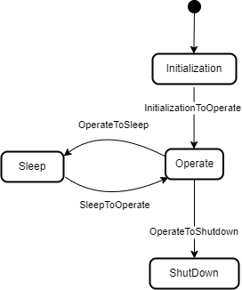
The LADSDeviceStateMachineType state machine represents the Device's current state. It is inspired by the AnalyserDeviceStateMachineType from the Analyzer Devices Specification.
The LADSDeviceStateMachine is depicted in Figure 15
The LADSDeviceStateMachineType is formally defined in Table 17.
| Attribute | Value | ||||
| BrowseName | LADSDeviceStateMachineType | ||||
| IsAbstract | False | ||||
| References | Node Class | BrowseName | DataType | TypeDefinition | Other |
|---|---|---|---|---|---|
| Subtype of the FiniteStateMachineType defined in OPC 10000-5 | |||||
| 0:HasComponent | Method | GotoOperate | O | ||
| 0:HasComponent | Method | GotoShutdown | O | ||
| 0:HasComponent | Method | GotoSleep | O | ||
| 0:HasComponent | Object | Operate | StateType | ||
| 0:HasComponent | Object | OperateToShutdown | TransitionType | ||
| 0:HasComponent | Object | OperateToSleep | TransitionType | ||
| 0:HasComponent | Object | Initialization | InitialStateType | ||
| 0:HasComponent | Object | InitializationToOperate | TransitionType | ||
| 0:HasComponent | Object | Shutdown | StateType | ||
| 0:HasComponent | Object | Sleep | StateType | ||
| 0:HasComponent | Object | SleepToOperate | TransitionType | ||
| Conformance Units | |||||
|---|---|---|---|---|---|
| LADS LADSDeviceStateMachineType | |||||
There are four Device states, as follows:
Initialization: The Device is in its initializing sequence and cannot perform any other Task.
Operate: The Device is in Operating mode. The LADS Client uses this mode for normal operation: configuration, control, and data collection.
Sleep: The Device is still powered on and its OPC UA Server is still running, but it is not ready to perform any Tasks until it transitions to the Operate state. This state can be used to represent a PowerSave state where a Device may shut down some of its Components, such as the GUI. It can also be used to represent a Sleep state, where a Device is running with minimal services but ready to be triggered to transition into the Operate state.
Shutdown: The Device is in its power-down sequence and cannot perform any other Task. Optionally, there are devices that can be powered off via physical means, especially simpler ones. The electronics are turned off immediately; therefore, such devices do not transition into a Shutdown state.
Note: Shutdown is the state in which the LADS Device waits for the completion of the power down sequence. Its sub-states are out of scope of the LADS specification.
Children of the LADSDeviceStateMachineType have additional References, which are defined in Table 18.
| SourceBrowsePath | Reference Type | Is Forward | TargetBrowsePath |
| InitializationToOperate | 0:FromState | True | Initialization |
| 0:ToState | True | Operate | |
| 0:HasEffect | True | TransitionEventType | |
| OperateToSleep | 0:FromState | True | Operate |
| 0:ToState | True | Sleep | |
| 0:HasCause | True | GotoSleep | |
| 0:HasEffect | True | TransitionEventType | |
| SleepToOperate | 0:FromState | True | Sleep |
| 0:ToState | True | Operate | |
| 0:HasCause | True | GotoOperate | |
| 0:HasEffect | True | TransitionEventType | |
| OperateToShutdown | 0:FromState | True | Operate |
| 0:ToState | True | Shutdown | |
| 0:HasCause | True | GotoShutdown | |
| 0:HasEffect | True | TransitionEventType |
The Component Variables of the LADSDeviceStateMachineType have additional Attributes, as defined in Table 19.
| BrowsePath | Value Attribute | ||
| 1 | ||
| 2 | ||
| 3 | ||
| 4 | ||
| 3 | ||
| 4 | ||
| 2 | ||
| 1 |
7.1.2.2 GotoOperate
The GotoOperate Method is used to set the Device into an operating mode. The signature of this Method is specified below. Table 20 specifies its representation in the AddressSpace.
Signature
GotoOperate ()| Attribute | Value | ||||
| BrowseName | GotoOperate | ||||
| References | Node Class | BrowseName | DataType | TypeDefinition | ModellingRule |
|---|
7.1.2.3 GotoShutdown
The GotoShutdown Method is used to shut down the Device. The signature of this Method is specified below. Table 21 specifies its representation in the AddressSpace.
Signature
GotoShutdown ()| Attribute | Value | ||||
| BrowseName | GotoShutdown | ||||
| References | Node Class | BrowseName | DataType | TypeDefinition | ModellingRule |
|---|---|---|---|---|---|
7.1.2.4 GotoSleep
The GotoSleep Method is used to set the Device to Sleep. The signature of this Method is specified below. Table 22 specifies its representation in the AddressSpace.
Signature
GotoSleep ()| Attribute | Value | ||||
| BrowseName | GotoSleep | ||||
| References | Node Class | BrowseName | DataType | TypeDefinition | ModellingRule |
|---|
7.1.3 LADSComponentType ObjectType Definition
Devices may be composed of tangible subcomponents. A Component is represented by the LADSComponentType. A Component itself may also have subcomponents. The LADSComponentType is formally defined in Table 23.
| Attribute | Value | ||||
| BrowseName | LADSComponentType | ||||
| IsAbstract | False | ||||
| References | Node Class | BrowseName | DataType | TypeDefinition | Other |
|---|---|---|---|---|---|
| Subtype of the 2:ComponentType defined in OPC 10000-100 | |||||
| 0:HasAddIn | Object | Components | LADSComponentsType | O | |
| 0:HasAddIn | Object | 2:Identification | M | ||
| 0:HasComponent | Object | Maintenance | MaintenanceSetType | O | |
| 0:HasProperty | Variable | 3:OperationalLocation | 0:String | 0:PropertyType | O |
| 0:HasProperty | Variable | 3:HierarchicalLocation | 0:String | 0:PropertyType | O |
| 0:Organizes | Object | 4:MachineryBuildingBlocks | 0:FolderType | O | |
| 0:HasAddIn | Object | 2:OperationCounters | 4:MachineryOperationCounterType | O | |
| 0:HasAddIn | Object | 4:LifetimeCounters | 4:MachineryLifetimeCounterType | O | |
| 0:HasInterface | ObjectType | 2:IDeviceHealthType | |||
| Applied from 2:IDeviceHealthType | |||||
| 0:HasComponent | Variable | 2:DeviceHealth | 2:DeviceHealthEnumeration | 0:BaseDataVariableType | O |
| 0:HasComponent | Object | 2:DeviceHealthAlarms | 0:FolderType | O | |
| Conformance Units | |||||
|---|---|---|---|---|---|
| LADS LADSComponentType | |||||
Components is a generic set of identifiable subcomponents of the device as mandated by OPC 40001-1.
Identification provides the properties to identify a device.
Recommendations for Identification:
• If the Component consists solely of software with no hardware, the SoftwareRevision should be provided and the HardwareRevision should be omitted.
• If the Component consists solely of hardware with no software, the HardwareRevision should be provided and the SoftwareRevision should be omitted.
• If the Component consists of both hardware and software, the HardwareRevision should be provided. The SoftwareRevision should be provided if there are no subcomponents providing a SoftwareRevision. Otherwise, the SoftwareRevision may be provided to represent the overall revision of all software components.
HierarchicalLocation provides the hierarchical location of the LADS Device. The structure inside the string may expose several levels. How this is exposed, which delimiters are used, etc. is vendor specific. Examples of such strings are "FactoryA/BuildingC/Floor1" or "Area1-ProcessCell17-Unit4" (see OPC 10000-110 for more Details).
OperationalLocation provides the operational location of the LADS Device. The structure within the string may expose several levels. How this is exposed, which delimiters are used, etc. is vendor specific. Examples of such strings are "Warehouse1/Sheet3" or "StainlessSteelTote3" (see OPC 10000-110 for more Details).
Recommendations for both hierarchical and operational locations have been proposed:
For instances where the location definition encompasses multiple levels, these levels should be separated by the delimiter character "/". An instance of a location definition with multiple levels separated by the delimiting character "/" is "US-NY-NYC-Building101/Floor35/Room10.1".
For additional use cases not covered by the aforementioned properties, it is recommended to employ the additional location formats NmeaCoordinateString, LocalCoordinate, and WGS84Coordinate as delineated in the OPC UA for AutoId Devices Release 1.01.1 (2021-07-13) specification.
DeviceHealth indicates the health status of a Device as defined by NAMUR Recommendation NE 107 (see OPC 10000-100 for more Details).
DeviceHealthAlarms groups all instances of Device health-related Alarms.
OperationCounters for monitoring the operation of a LADSDeviceType, including parameters of the OperationCounters interface and lifetime variables (see OPC 10000-100 for more information).
Maintenance is a set containing all maintenance tasks of a Device.
The MachineryBuildingBlocks folder contains all machinery building blocks, especially the OperationCounter, and Lifetime Counter.
OperationCounter provides information on how long a MachineryItem has been turned on and how long it performed an activity. It uses the 2:IOperationCounterType interface and the predefined functional group 2:OperationCounters defined in OPC 10000-100.
Lifetime Counter provides information about the past and estimated remaining lifetime of a MachineryItem, or other aspects of a MachineryItem such as a software license. It is based on the 2:LifetimeVariableType defined in OPC 10000-100.
Children of the LADSComponentsType have additional References, which are defined in Table 24.
| SourceBrowsePath | Reference Type | Is Forward | TargetBrowsePath | ||
| 4:MachineryBuildingBlocks | 0:HasAddIn | True |
| ||
| 4:MachineryBuildingBlocks | 0:HasAddIn | True |
| ||
| 4:MachineryBuildingBlocks | 0:HasAddIn | True |
|
7.1.4 FunctionalUnitType ObjectType Definition
The FunctionalUnitType represents a functional unit of a Laboratory or Analytical Device. It is formally defined in Table 25.
| Attribute | Value | ||||
| BrowseName | FunctionalUnitType | ||||
| IsAbstract | False | ||||
| References | Node Class | BrowseName | DataType | TypeDefinition | Other |
| Subtype of the TopologyElementType defined in OPC 10000-100 | |||||
| 0:HasComponent | Object | ProgramManager | ProgramManagerType | O | |
| 0:HasComponent | Object | FunctionalUnitState | FunctionalUnitStateMachineType | M | |
| 0:HasComponent | Object | SupportedPropertiesSet | SupportedPropertiesSetType | O | |
| 0:HasComponent | Object | FunctionSet | FunctionSetType | O | |
| 0:HasComponent | Object | Operational | 1:FunctionalGroupType | O | |
| 0:HasInterface | ObjectType | 2:ITagNameplateType | |||
| Implements the 2:ITagNameplateType | |||||
| 0:HasProperty | Variable | 2:AssetId | 0:String | 0:PropertyType | O |
| 0:HasProperty | Variable | 2:ComponentName | LocalizedText | 0:PropertyType | O |
| Conformance Units | |||||
| LADS FunctionalUnitType | |||||
AssetId is a user-writeable alphanumeric character sequence that uniquely identifies a FunctionalUnit (see OPC UA 10000-100).
ComponentName is a user-writeable name provided by the integrator or user of the FunctionalUnit.
FunctionSet contains the Functions of the FunctionalUnit.
Program Manager manages the programs and results of the FunctionalUnit.
FunctionalUnitState the StateMachine that is used for this FunctionalUnit.
Operational Functional Group that organizes Properties and Methods for this FunctionalUnit.
SupportedPropertiesSet provides references to variables of sub-ordinate Functions of the FunctionalUnit whose values can be specified as input Arguments when calling the FunctionalUnit.FunctionalUnitState.Start() or ProgramManager.ActiveProgram.StateMachine.Start() Methods.
7.1.5 FunctionalStateMachineType ObjectType Definition
7.1.5.1 Overview
The FunctionalStateMachineType is the top level StateMachine for the LADS ActiveProgram, FunctionalUnit or Function. The basic idea behind this architecture is that the instances of the FunctionalStateMachineType, the ActiveProgramStateMachineType, the FunctionalUnitStateMachineType and the FunctionStateMachineType use the same states, Transitions and Methods, but add their own Start Methods with different Method Signatures to trigger the StoppedToRunning Transition from a Client.
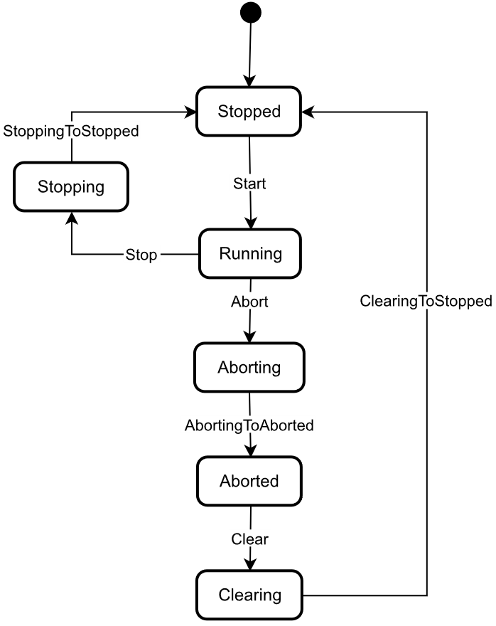
The FunctionalStateMachineType defines the available states in a LADS system.
The FunctionalStateMachineType is formally defined in Table 26. StateTypes and TransitionTypes only exist in the type system, thus they do not have a modelling rule.
The FunctionalStateMachine is depicted in Figure 16.
| Attribute | Value | ||||
| BrowseName | FunctionalStateMachineType | ||||
| IsAbstract | True | ||||
| References | Node Class | BrowseName | DataType | TypeDefinition | Other |
|---|---|---|---|---|---|
| Subtype of the 0:FiniteStateMachineType defined in OPC 10000-5 | |||||
| 0:HasComponent | Variable | 0:AvailableTransitions | 0:NodeId[] | 0:BaseDataVariableType | M |
| 0:HasComponent | Variable | 0:AvailableStates | 0:NodeId[] | 0:BaseDataVariableType | M |
| 0:HasComponent | Method | Abort | O | ||
| 0:HasComponent | Object | Aborted | StateType | ||
| 0:HasComponent | Object | AbortedToClearing | TransitionType | ||
| 0:HasComponent | Object | Aborting | StateType | ||
| 0:HasComponent | Object | AbortingToAborted | TransitionType | ||
| 0:HasComponent | Method | Clear | O | ||
| 0:HasComponent | Object | Clearing | StateType | ||
| 0:HasComponent | Object | ClearingToStopped | TransitionType | ||
| 0:HasComponent | Object | Running | StateType | ||
| 0:HasComponent | Object | RunningStateMachine | RunningStateMachineType | O | |
| 0:HasComponent | Object | RunningToAborting | TransitionType | ||
| 0:HasComponent | Object | RunningToStopping | TransitionType | ||
| 0:HasComponent | Method | Stop | O | ||
| 0:HasComponent | Object | Stopped | InitialStateType | ||
| 0:HasComponent | Object | StoppedToRunning | TransitionType | ||
| 0:HasComponent | Object | Stopping | StateType | ||
| 0:HasComponent | Object | StoppingToStopped | TransitionType | ||
| 0:HasComponent | Variable | 0:CurrentState | 0:LocalizedText | FiniteStateVariableType | M |
| Conformance Units | |||||
|---|---|---|---|---|---|
| LADS FunctionalStateMachineType | |||||
The AvailableTransitions and AvailableStates Nodes are overwritten and made Mandatory in the FunctionalStateMachineType.
Abort is a Method to trigger a change of state to Aborting. This will affect all sub-states in a cleared state.
Aborted maintains unit/device status information relevant to the Abort condition. The unit/device can only exit the Aborted state after an explicit Clear command subsequent to manual intervention to correct and reset the detected unit/device faults.
Aborting represents a state that can be entered at any time in response to the Abort command or in the event of a unit/device fault. The aborting logic will bring the unit/device to a rapid safe stop. Operation of the emergency stop will cause the unit/device to be tripped by its safety system. It will also provide a signal to initiate the Aborting state.
Clear is a Method to trigger a change of state to Cleared.
Clearing is initiated by a state command to clear faults that may have occurred when Aborting that are present in the Aborted state.
Running is the state when the ActiveProgram, Function or FunctionalUnit is currently running/executing.
RunningStateMachine is a RunningStateMachineType that details the Running state.
Stop is a Method to trigger a change of state to Stopped. This will affect all sub-states in a Run state.
Stopped is the initial state for an ActiveProgram, FunctionalUnit or Function. It is an Idle state which means that the Function, FunctionalUnit or ActiveProgram is stopped and ready for activation. It can also be used to represent a non-running state, potentially caused by an error, where the Function, FunctionalUnit or ActiveProgram can invoke the Reset() Function before starting again.
Stopping indicates that the ActiveProgram, FunctionalUnit, or Function is in the process of stopping. This state usually occurs when the program execution is finished or stopped, either because it has ended or has been triggered by the Stop Method.
The Transitions of the FunctionalStateMachineType have additional References which are defined in Table 27. This StateMachine includes the transition from Unholding to Holding, Starting, Unsuspending, Suspended, and Suspending, all of which are extensions to the ISA-TR88.00.02-2015 specification.
| SourceBrowsePath | Reference Type | Is Forward | TargetBrowsePath |
| AbortedToClearing | 0:FromState | True | Aborted |
| 0:ToState | True | Clearing | |
| 0:HasCause | True | Clear | |
| 0:HasEffect | True | TransitionEventType | |
| AbortingToAborted | 0:FromState | True | Aborting |
| 0:ToState | True | Aborted | |
| 0:HasEffect | True | TransitionEventType | |
| ClearingToStopped | 0:FromState | True | Clearing |
| 0:ToState | True | Stopped | |
| 0:HasEffect | True | TransitionEventType | |
| RunningToAborting | 0:FromState | True | Running |
| 0:ToState | True | Aborting | |
| 0:HasCause | True | Abort | |
| 0:HasEffect | True | TransitionEventType | |
| RunningToStopping | 0:FromState | True | Running |
| 0:ToState | True | Stopping | |
| 0:HasCause | True | Stop | |
| 0:HasEffect | True | TransitionEventType | |
| StoppedToRunning | 0:FromState | True | Stopped |
| 0:ToState | True | Running | |
| 0:HasEffect | True | TransitionEventType | |
| StoppingToStopped | 0:FromState | True | Stopping |
| 0:ToState | True | Stopped | |
| 0:HasEffect | True | TransitionEventType | |
| Running | 0:HasSubStateMachine | True | RunningStateMachine |
The Component Variables of the FunctionalStateMachineType have additional Attributes, as defined in Table 28.
| BrowsePath | Value Attribute | ||
| 1 | ||
| 2 | ||
| 3 | ||
| 5 | ||
| 4 | ||
| 6 | ||
| 1 | ||
| 2 | ||
| 4 | ||
| 5 | ||
| 6 | ||
| 7 | ||
| 8 |
7.1.5.2 Abort
The Abort Method switches the state machine to the Aborting state. The current process will be aborted. The signature of this Method is specified below. Table 29 specifies its representation in the AddressSpace.
Signature
Abort ()| Attribute | Value | ||||
| BrowseName | Abort | ||||
| References | Node Class | BrowseName | DataType | TypeDefinition | ModellingRule |
|---|---|---|---|---|---|
7.1.5.3 Clear
The Clear Method allows an OPC UA Client to change the state of this state machine to the Cleared state. The signature of this Method is specified below. Table 30 specifies its representation in the AddressSpace.
Signature
Clear ()| Attribute | Value | ||||
| BrowseName | Clear | ||||
| References | Node Class | BrowseName | DataType | TypeDefinition | ModellingRule |
|---|---|---|---|---|---|
7.1.5.4 Stop
The Stop Method allows an OPC UA Client to change the state of this state machine to the Stopping state. The signature of this Method is specified below. Table 31 specifies the Arguments and AddressSpace representation.
Signature
Stop ()| Attribute | Value | ||||
| BrowseName | Stop | ||||
| References | Node Class | BrowseName | DataType | TypeDefinition | ModellingRule |
|---|---|---|---|---|---|
7.1.6 RunningStateMachineType ObjectType Definition
7.1.6.1 Overview
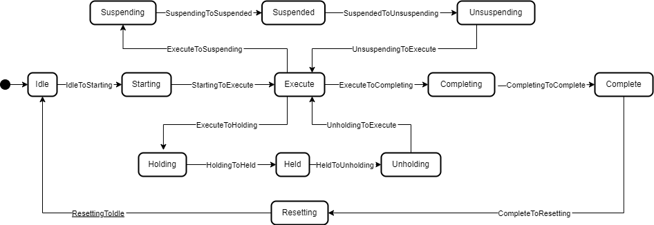
The RunningStateMachineType is a sub-state machine of the FunctionalStateMachine and includes detailed substates. It is formally defined in Table 32.
The Running StateMachine is depicted in Figure 17.
| Attribute | Value | ||||
| BrowseName | RunningStateMachineType | ||||
| IsAbstract | False | ||||
| References | Node Class | BrowseName | DataType | TypeDefinition | Other |
|---|---|---|---|---|---|
| Subtype of the FiniteStateMachineType defined in OPC 10000-5 | |||||
| 0:HasComponent | Object | Complete | StateType | ||
| 0:HasComponent | Object | CompleteToResetting | TransitionType | ||
| 0:HasComponent | Object | Completing | StateType | ||
| 0:HasComponent | Object | CompletingToComplete | TransitionType | ||
| 0:HasComponent | Object | Execute | StateType | ||
| 0:HasComponent | Object | ExecuteToCompleting | TransitionType | ||
| 0:HasComponent | Object | ExecuteToHolding | TransitionType | ||
| 0:HasComponent | Object | ExecuteToSuspending | TransitionType | ||
| 0:HasComponent | Object | Held | StateType | ||
| 0:HasComponent | Object | HeldToUnholding | TransitionType | ||
| 0:HasComponent | Method | Hold | O | ||
| 0:HasComponent | Object | Holding | StateType | ||
| 0:HasComponent | Object | HoldingToHeld | TransitionType | ||
| 0:HasComponent | Object | Idle | StateType | ||
| 0:HasComponent | Object | IdleToStarting | TransitionType | ||
| 0:HasComponent | Method | Reset | O | ||
| 0:HasComponent | Object | Resetting | StateType | ||
| 0:HasComponent | Object | ResettingToIdle | TransitionType | ||
| 0:HasComponent | Object | Starting | StateType | ||
| 0:HasComponent | Object | StartingToExecute | TransitionType | ||
| 0:HasComponent | Object | StartingToHolding | TransitionType | ||
| 0:HasComponent | Method | Suspend | O | ||
| 0:HasComponent | Object | Suspended | StateType | ||
| 0:HasComponent | Object | SuspendedToHolding | TransitionType | ||
| 0:HasComponent | Object | SuspendedToUnsuspending | TransitionType | ||
| 0:HasComponent | Object | Suspending | StateType | ||
| 0:HasComponent | Object | SuspendingToHolding | TransitionType | ||
| 0:HasComponent | Object | SuspendingToSuspended | TransitionType | ||
| 0:HasComponent | Method | ToComplete | O | ||
| 0:HasComponent | Method | Unhold | O | ||
| 0:HasComponent | Object | Unholding | StateType | ||
| 0:HasComponent | Object | UnholdingToExecute | TransitionType | ||
| 0:HasComponent | Object | UnholdingToHolding | TransitionType | ||
| 0:HasComponent | Method | Unsuspend | O | ||
| 0:HasComponent | Object | Unsuspending | StateType | ||
| 0:HasComponent | Object | UnsuspendingToExecute | TransitionType | ||
| 0:HasComponent | Object | UnsuspendingToHolding | TransitionType | ||
| Conformance Units | |||||
|---|---|---|---|---|---|
| LADS RunningStateMachineType | |||||
Complete: Complete indicates that the process associated with the active protocol has come to its defined end. The unit/device will wait in this state until a Reset command is issued (in which case it will transition to Resetting), or until the unit/device is Stopped or Aborted.
Completing: Once the process associated with the current mode has reached a defined threshold (e.g., the required number of samples for the current job have been analysed or the cultivation/fermentation process has reached is final stage in terms of cell count, product yield, cell viability, etc.), the unit/device transitions from Execute to Completing. All steps necessary to shut down the current process are carried out in this state. The unit/device then transitions automatically to the Complete state.
Execute: The unit/device is actively carrying out the behaviour or activity defined by the selected protocol and its associated processing mode. Examples of a unit/device in processing mode include when the unit/device is performing an analytical run, cultivation/fermentation in the case of a bioreactor, or another defined unit of operation provided by the instrument (e.g., separation in the case of a centrifuge).
Held: The unit/device is paused, waiting for internal process conditions to clear. In this state, the unit/device shall not continue processing, although it may dry cycle if required (e.g., maintaining process conditions critical for the preservation of the samples or culture). A transition to Unholding will occur once internal unit/device conditions have cleared, or if the Unhold command is initiated by an operator.
Holding: The unit/device will transition from Execute to Holding if conditions internal to the unit/device require a pause in processing. Examples of such conditions include low levels of materials required for processing (e.g., consumables, reagents, buffers, etc.) or other minor issues requiring operator service. After all steps required to hold the unit/device have been completed, the unit/device will transition automatically to the Held state.
Idle: The unit/device is in an error-free state, waiting to start. The unit/device transitions automatically to Idle after all steps necessary for Resetting have been completed. All conditions achieved during Resetting are maintained. A Start command will transition the unit/device from Idle to Starting.
Resetting: In response to a Reset command, the unit/device will transition to Resetting from either Stopped or Complete. In this state the unit/device attempts to clear any standing errors or stop causes. If successful, the unit/device transitions to Idle. No hazardous motion should occur while in this state.
Starting: The unit/device completes all steps necessary to begin execution of the active protocol. Typical steps during this state include but are not limited to inspecting system setup (checking sufficient supplies of resources and consumables), priming of fluids, homing of handling systems, or equilibration of process conditions. A Start command will cause the unit/device to transition from Idle to Starting. The unit/device will transition automatically from Starting to Execute once all required steps have been completed.
Suspended: The unit/device is paused, waiting for external process conditions to clear. In this state, the unit/device shall not continue processing, but may dry cycle if required (e.g., maintaining process conditions critical for the preservation of the samples or culture, including but not limited to temperature, oxygen or pH levels, etc.). Once external conditions have returned to normal, the unit/device will transition to Unsuspending, with or without operator intervention.
Suspending: The unit/device will transition from Execute to Suspending if conditions external to the unit/device require a pause in processing. Such conditions include faults to upstream or downstream equipment. The decision to Suspend may be made by a human operator supervising the process, an automated supervisory system monitoring the conditions of the overall process line/workflow, or by unit/device Sensors detecting downstream blockages or upstream scarcity of samples, etc. (In the former case, the unit/device is 'blocked"; in the latter case, the unit/device is "starved".) After all steps required to suspend the unit/device have been completed, the unit/device will automatically transition to the Suspended state.
Unholding: After all internal process conditions that caused the unit/device to hold have cleared, the unit/device completes all steps required to resume execution of the active protocol. Once all required actions to unhold the unit/device have been completed, the unit/device will transition automatically to the Execute state.
Unsuspending: After all external process conditions that caused the unit/device to suspend have cleared, the unit/device completes all steps required to resume execution of the active protocol.
The children of the RunningStateMachineType have additional References, which are defined in Table 33.
| SourceBrowsePath | Reference Type | Is Forward | TargetBrowsePath |
| IdleToStarting | 0:FromState | True | Idle |
| 0:ToState | True | Starting | |
| 0:HasEffect | True | TransitionEventType | |
| StartingToExecute | 0:FromState | True | Starting |
| 0:ToState | True | Execute | |
| 0:HasEffect | True | TransitionEventType | |
| ExecuteToCompleting | 0:FromState | True | Execute |
| 0:ToState | True | Completing | |
| 0:HasCause | True | ToComplete | |
| 0:HasEffect | True | TransitionEventType | |
| CompletingToComplete | 0:FromState | True | Completing |
| 0:ToState | True | Complete | |
| 0:HasEffect | True | TransitionEventType | |
| CompleteToResetting | 0:FromState | True | Complete |
| 0:ToState | True | Resetting | |
| 0:HasCause | True | Reset | |
| 0:HasEffect | True | TransitionEventType | |
| ResettingToIdle | 0:FromState | True | Resetting |
| 0:ToState | True | Idle | |
| 0:HasEffect | True | TransitionEventType | |
| ExecuteToSuspending | 0:FromState | True | Execute |
| 0:ToState | True | Suspending | |
| 0:HasCause | True | Suspend | |
| 0:HasEffect | True | TransitionEventType | |
| SuspendingToSuspended | 0:FromState | True | Suspending |
| 0:ToState | True | Suspended | |
| 0:HasEffect | True | TransitionEventType | |
| UnsuspendingToExecute | 0:FromState | True | Unsuspending |
| 0:ToState | True | Execute | |
| 0:HasEffect | True | TransitionEventType | |
| ExecuteToHolding | 0:FromState | True | Execute |
| 0:ToState | True | Holding | |
| 0:HasCause | True | Hold | |
| 0:HasEffect | True | TransitionEventType | |
| HoldingToHeld | 0:FromState | True | Holding |
| 0:ToState | True | Held | |
| 0:HasEffect | True | TransitionEventType | |
| HeldToUnholding | 0:FromState | True | Held |
| 0:ToState | True | Unholding | |
| 0:HasCause | True | Unhold | |
| 0:HasEffect | True | TransitionEventType | |
| UnholdingToExecute | 0:FromState | True | Unholding |
| 0:ToState | True | Execute | |
| 0:HasEffect | True | TransitionEventType |
| SourceBrowsePath | Reference Type | Is Forward | TargetBrowsePath |
| SuspendingToHolding | 0:FromState | True | Suspending |
| 0:ToState | True | Holding | |
| 0:HasCause | True | Hold | |
| 0:HasEffect | True | TransitionEventType | |
| StartingToHolding | 0:FromState | True | Starting |
| 0:ToState | True | Holding | |
| 0:HasCause | True | Hold | |
| 0:HasEffect | True | TransitionEventType | |
| SuspendedToHolding | 0:FromState | True | Suspended |
| 0:ToState | True | Holding | |
| 0:HasCause | True | Hold | |
| 0:HasEffect | True | TransitionEventType | |
| UnsuspendingToHolding | 0:FromState | True | Unsuspending |
| 0:ToState | True | Holding | |
| 0:HasCause | True | Hold | |
| 0:HasEffect | True | TransitionEventType | |
| UnholdingToHolding | 0:FromState | True | Unholding |
| 0:ToState | True | Holding | |
| 0:HasCause | True | Hold | |
| 0:HasEffect | True | TransitionEventType |
The Component Variables of the RunningStateMachineType have additional Attributes, as defined in Table 34.
| BrowsePath | Value Attribute | ||
| 1 | ||
| 2 | ||
| 3 | ||
| 4 | ||
| 5 | ||
| 6 | ||
| 7 | ||
| 8 | ||
| 9 | ||
| 10 | ||
| 11 | ||
| 12 | ||
| 1 | ||
| 2 | ||
| 5 | ||
| 6 | ||
| 7 | ||
| 8 | ||
| 9 | ||
| 10 | ||
| 11 | ||
| 12 |
| BrowsePath | Value Attribute | ||
| 13 | ||
| 14 | ||
| 15 | ||
| 16 | ||
| 17 | ||
| 18 | ||
| 19 |
7.1.6.2 Hold
The Hold Method allows an OPC UA Client to change the state of this state machine to Holding. The signature of this Method is specified below. Table 35 specifies its representation in the AddressSpace.
Signature
Hold ()| Attribute | Value | ||||
| BrowseName | Hold | ||||
| References | Node Class | BrowseName | DataType | TypeDefinition | ModellingRule |
|---|---|---|---|---|---|
7.1.6.3 Reset
The Reset Method allows an OPC UA Client to change the state of this state machine to Resetting. The signature of this Method is specified below. Table 36 specifies its representation in the AddressSpace.
Signature
Reset ()| Attribute | Value | ||||
| BrowseName | Reset | ||||
| References | Node Class | BrowseName | DataType | TypeDefinition | ModellingRule |
|---|---|---|---|---|---|
7.1.6.4 Suspend
The Suspend Method allows an OPC UA Client to change the state of this state machine to the Suspending state. The signature of this Method is specified below. Table 37 specifies its representation in the AddressSpace.
Signature
Suspend ()| Attribute | Value | ||||
| BrowseName | Suspend | ||||
| References | Node Class | BrowseName | DataType | TypeDefinition | ModellingRule |
|---|
7.1.6.5 ToComplete
The ToComplete Method allows an OPC UA Client to change the state of this state machine to Completed. The signature of this Method is specified below. Table 38 specifies its representation in the AddressSpace.
Signature
ToComplete ()| Attribute | Value | ||||
| BrowseName | ToComplete | ||||
| References | Node Class | BrowseName | DataType | TypeDefinition | ModellingRule |
|---|---|---|---|---|---|
7.1.6.6 Unhold
The Unhold Method allows an OPC UA Client to change the state of this state machine to Unholding. The signature of this Method is specified below. Table 39 specifies its representation in the AddressSpace.
Signature
Unhold ()| Attribute | Value | ||||
| BrowseName | Unhold | ||||
| References | Node Class | BrowseName | DataType | TypeDefinition | ModellingRule |
|---|---|---|---|---|---|
7.1.6.7 Unsuspend
The Unsuspend Method allows an OPC UA Client to change the state of this state machine to Unsuspending. The signature of this Method is specified below. Table 40 specifies its representation in the AddressSpace.
Signature
Unsuspend ()| Attribute | Value | ||||
| BrowseName | Unsuspend | ||||
| References | Node Class | BrowseName | DataType | TypeDefinition | ModellingRule |
|---|---|---|---|---|---|
7.1.7 FunctionalUnitStateMachineType Definition
7.1.7.1 Overview
The FunctionalUnitStateMachineType represents the state of a FunctionalUnit in a LADS Device. It uses the same StateTypes and TransitionTypes as its parent but specifies the additional Start Method to trigger state changes.
The FunctionalUnitStateMachineType is formally defined in Table 41.
| Attribute | Value | ||||
| BrowseName | FunctionalUnitStateMachineType | ||||
| IsAbstract | False | ||||
| References | Node Class | BrowseName | DataType | TypeDefinition | Other |
|---|---|---|---|---|---|
| Subtype of the FunctionalStateMachineType defined in 7.1.5 | |||||
| 0:HasComponent | Method | Start | O | ||
| 0:HasComponent | Method | StartProgram | O | ||
| Conformance Units | |||||
|---|---|---|---|---|---|
| LADS FunctionalUnitStateMachineType | |||||
Start is used to start a FunctionalUnit with properties.
StartProgram is used to start a FunctionalUnit with a Program Template.
7.1.7.2 Start
The Start Method is used when a Client application wants to initiate/execute an/the operation of a FunctionalUnit. The Properties Argument can be used to provide an optional list of property values when initiating the operation. The listed items represent key-value pairs that conform to the OPC UA KeyValuePair core datatype. The qualified name provided via the key field must match the BrowseName of a Property member in the FunctionalUnit's SupportedPropertySet.
The signature of this Method is specified below. Table 42 and Table 43 specify the Arguments and AddressSpace representation, respectively.
The Start Method should not be called by a Client with anonymous authentication.
Signature
	Start (
[in] KeyValuePair[] Properties)| Argument | Description |
| Properties | A set of Properties that parameterize the execution of the Functional Unit. |
| Attribute | Value | ||||
| BrowseName | Start | ||||
| References | Node Class | BrowseName | DataType | TypeDefinition | ModellingRule |
|---|---|---|---|---|---|
| 0:HasProperty | Variable | 0:InputArguments | Argument[1] | 0:PropertyType | M |
7.1.7.3 StartProgram
The StartProgram Method is used when a Client application wants to start running a program based on a ProgramTemplate of a FunctionalUnit. The Properties Argument can be used to provide an optional list of property values when initiating a program run. The listed items represent key-value pairs that conform to the OPC UA KeyValuePair core datatype. The qualified name provided via the key field must match the BrowseName of a Property member in the FunctionalUnit's SupportedPropertySet.
In contrast to the Start Method, additional fixed properties must also be set.
The signature of this Method is specified below. Table 44 and Table 45 specify the Arguments and AddressSpace representation, respectively.
The Start Method should not be called by a Client with anonymous authentication.
Signature
	StartProgram (
		[in]	0:String	ProgramTemplateId
		[in]	KeyValueType[]	Properties
		[in]	0:String	SupervisoryJobId
		[in]	0:String	SupervisoryTaskId
		[in]	SampleInfoType[]	Samples
[out] 0:String DeviceProgramRunId)| Argument | Description |
| ProgramTemplateId | The unique identifier of the program template used for the program-run. The template must be a member of the ProgramTemplateSet. |
| Properties | A Key/Value set for parameterization of the function. |
| SupervisoryJobId | The SupervisoryJobId assigned to this program. |
| SupervisoryTaskId | The Id of the SupervisoryTask. |
| Samples | An array of the SampleInfoType that describes the samples processed in this program-run. |
| DeviceProgramRunId | The Id of the created program run. |
| Attribute | Value | ||||
| BrowseName | StartProgram | ||||
| References | Node Class | BrowseName | DataType | TypeDefinition | ModellingRule |
|---|---|---|---|---|---|
| 0:HasProperty | Variable | 0:InputArguments | Argument[5] | 0:PropertyType | M |
| 0:HasProperty | Variable | 0:OutputArguments | Argument[1] | 0:PropertyType | M |
DeviceProgramRunId is the internal program identifier assigned by the Device to the program run to generate this result. It is used to identify a Result object and is returned to the Client when the StartProgram Method is called.
SupervisoryJobId is the identifier for the execution of a specific workflow, consisting of one or multiple tasks. It is provided as an Argument of the StartProgram() Method which initiates the program run.
SupervisoryTaskId is the unique identifier of the specific task in the supervisory system to which the result belongs. It is provided as an Argument of the StartProgram() Method which initiates the program run.
7.1.8 LADSComponentsType ObjectType Definition
The LADSComponentsType is used for organising LADSComponentsType objects in an unordered list structure. It is formally defined in Table 46.
| Attribute | Value | ||||
| BrowseName | LADSComponentsType | ||||
| IsAbstract | False | ||||
| References | Node Class | BrowseName | DataType | TypeDefinition | Other |
|---|---|---|---|---|---|
| Subtype of the MachineComponentsType defined in OPC 40001-1 | |||||
| 0:HasComponent | Object | <Component> | LADSComponentType | OP | |
| GeneratesEvent | ObjectType | GeneralModelChangeEventType | |||
| 0:HasProperty | Variable | NodeVersion | 0:String | 0:PropertyType | O |
| Conformance Units | |||||
|---|---|---|---|---|---|
| LADS LADSComponentsType | |||||
<Components> is a placeholder for the Components.
7.1.9 LADSOperationModeStateMachineType ObjectType Definition
The LADSOperationModeStateMachineType is a subtype of 4:MachineryOperationModeStateMachineType that adds optional Methods to the statemachine. It is formally defined in Table 46.
| Attribute | Value | ||||
| BrowseName | LADSOperationModeStateMachineType | ||||
| IsAbstract | False | ||||
| References | Node Class | BrowseName | DataType | TypeDefinition | Other |
|---|---|---|---|---|---|
| Subtype of the 4:MachineryOperationModeStateMachineType | |||||
| 0:HasComponent | Method | GotoMaintenance | O | ||
| 0:HasComponent | Method | GotoProcessing | O | ||
| 0:HasComponent | Method | GotoSetup | O | ||
| Conformance Units | |||||
|---|---|---|---|---|---|
| LADS LADSOperationModeStatemachineType | |||||
7.1.9.1 GotoMaintenance
The GotoMaintenance Method brings the LADSDevice in the Maintenance state.
The signature of this Method is specified below. Table 52 specifies its representation in the AddressSpace.
Signature
GotoMaintenance ()| Attribute | Value | ||||
| BrowseName | GotoMaintenance | ||||
| References | Node Class | BrowseName | DataType | TypeDefinition | ModellingRule |
|---|
7.1.9.2 GotoProcessing
The GotoMaintenance Method brings the LADSDevice in the Processing state.
The signature of this Method is specified below. Table 52 specifies its representation in the AddressSpace.
Signature
GotoProcessing ()| Attribute | Value | ||||
| BrowseName | GotoProcessing | ||||
| References | Node Class | BrowseName | DataType | TypeDefinition | ModellingRule |
|---|
7.1.9.3 GotoSetup
The GotoSetup Method brings the LADSDevice in the Setup state.
The signature of this Method is specified below. Table 52 specifies its representation in the AddressSpace.
Signature
GotoSetup ()| Attribute | Value | ||||
| BrowseName | GotoSetup | ||||
| References | Node Class | BrowseName | DataType | TypeDefinition | ModellingRule |
|---|
7.1.10 MaintenanceTaskType Definition
7.1.10.1 Overview
The MaintenanceTaskType shall be used to implement instances of maintenance tasks applicable at both the Device and Component levels. Maintenance tasks include activities such as periodic maintenance, cleaning, calibration, and validation.
Maintenance tasks for a Device shall be grouped under the Maintenance functional group present in the LADSDeviceType.
The MaintenanceTaskType is formally defined in Table 51.
| Attribute | Value | ||||
| BrowseName | MaintenanceTaskType | ||||
| IsAbstract | False | ||||
| References | Node Class | BrowseName | DataType | TypeDefinition | Other |
|---|---|---|---|---|---|
| Subtype of the MaintenanceRequiredAlarmType defined in OPC 10000-100 | |||||
| 0:HasProperty | Variable | LastExecutionDate | 0:UtcTime | 0:PropertyType | O |
| 0:HasProperty | Variable | LastOperatingCycles | 0:UInt32 | 0:PropertyType | O |
| 0:HasProperty | Variable | LastOperatingTime | 0:Duration | 0:PropertyType | O |
| 0:HasProperty | Variable | NextOperatingCycles | 0:UInt32 | 0:PropertyType | O |
| 0:HasProperty | Variable | NextOperatingTime | 0:Duration | 0:PropertyType | O |
| 0:HasProperty | Variable | RecurrencePeriod | 0:Duration | 0:PropertyType | O |
| 0:HasComponent | Method | ResetTask | O | ||
| 0:HasComponent | Method | StartTask | O | ||
| 0:HasComponent | Method | StopTask | O | ||
| 0:HasInterface | ObjectType | IMaintenanceEventType | Defined in OPC 10000-110 Section 12.2 | ||
| Applied from IMaintenanceEventType | |||||
| 0:HasProperty | Variable | 3:ConfigurationChanged | 0:Boolean | 0:PropertyType | O |
| 0:HasProperty | Variable | 3:EstimatedDowntime | 0:Duration | 0:PropertyType | O |
| 0:HasProperty | Variable | 3:MaintenanceMethod | 3:MaintenanceMethodEnum | 0:PropertyType | O |
| 0:HasComponent | Object | 3:MaintenanceState | 3:MaintenanceEventStateMachineType | M | |
| 0:HasProperty | Variable | 3:MaintenanceSupplier | 3:NameNodeIdDataType | 0:PropertyType | O |
| 0:HasProperty | Variable | 3:PartsOfAssetReplaced | 3:NameNodeIdDataType[] | 0:PropertyType | O |
| 0:HasProperty | Variable | 3:PartsOfAssetServiced | 3:NameNodeIdDataType[] | 0:PropertyType | O |
| 0:HasProperty | Variable | 3:PlannedDate | 0:UtcTime | 0:PropertyType | O |
| 0:HasProperty | Variable | 3:QualificationOfPersonnel | 3:NameNodeIdDataType | 0:PropertyType | O |
| Conformance Units | |||||
|---|---|---|---|---|---|
| LADS MaintenanceTaskType | |||||
LastExecutionDate is the date when the Task was last performed. Optional, as the Task may have never run before.
LastOperatingCycles is the number of cycles during the operating time (as defined in Section 9.3 of EN 13306-2017) recorded at the time of the last execution of the Task.
LastOperatingTime is the total amount of operating time (as defined in Section 9.3 of EN 13306-2017) in milliseconds (ms) by the Device at the time of the last execution of the Task.
NextOperatingCycles is the number of cycles during operating time (as defined in Section 9.3 of EN 13306-2017) to be completed before the next execution of the Task.
NextOperatingTime is the total amount of operating time (as defined in Section 9.3 of EN 13306-2017) in milliseconds (ms) by the Device before the next execution of the Task.
RecurrencePeriod is the period of repetition of the Task, specified in milliseconds. Optional, as not all Tasks have a recurrence period.
ResetTask Method resets the condition of the Task so that it is ready to be re-run.
Start Method starts the execution of the Task.
Stop Method stops the execution of the Task.
7.1.10.2 ResetTask
The ResetTask Method resets the execution of the Task so that it is ready to be re-run.
Optional, as instruments may not support resetting a maintenance task via a method call. The same effect can be achieved by means of a device-specific control.
Upon successful execution of the ResetTask Method, the MaintenanceState shall be changed to Planned and an accompanying event shall be raised. Also, the ActiveState and AckState properties are set to "False".
The signature of this Method is specified below. Table 52 specifies its representation in the AddressSpace.
Signature
ResetTask ()| Attribute | Value | ||||
| BrowseName | Reset | ||||
| References | Node Class | BrowseName | DataType | TypeDefinition | ModellingRule |
|---|
7.1.10.3 StartTask
The Start Method starts the execution of the Task.
Optional, as instruments may not support starting a maintenance task via a method call. The same effect can be achieved by means of a device-specific control.
Upon successful execution of the Start Method, the MaintenanceState shall be changed to Executing and an accompanying event shall be raised.
The signature of this Method is specified below. Table 53 specifies its representation in the AddressSpace.
Signature
StartTask ()| Attribute | Value | ||||
| BrowseName | StartTask | ||||
| References | Node Class | BrowseName | DataType | TypeDefinition | ModellingRule |
|---|
7.1.10.4 StopTask
The StopTask Method stops of the execution of the task.
Optional, as instruments may not support aborting the task via a method call. The same effect can be achieved by means of a device-specific control.
It includes 2 optional input parameters: MaintenanceTaskStopResult and Comment to document the outcome of the maintenance task.
Upon successful execution of the Stop Method, the MaintenanceState shall be changed to Finished and an accompanying event shall be raised. Also, the ActiveState and AckState properties are set to "False".
The signature of this Method is specified below. Table 54 and Table 55 specify the Arguments and AddressSpace representation, respectively.
Signature
	StopTask (
		[in]	MaintenanceTaskResultEnum	MaintenanceTaskStopResult,
[in] LocalizedText Comment)| Argument | Description |
| MaintenanceTaskStopResult | Give the reason why the task is stopped. |
| Comment | Add an additional comment to describe the call |
| Attribute | Value | ||||
| BrowseName | StopTask | ||||
| References | Node Class | BrowseName | DataType | TypeDefinition | ModellingRule |
|---|---|---|---|---|---|
| 0:HasProperty | Variable | 0:InputArguments | 0:Argument[] | 0:PropertyType | 0:Mandatory |
7.2 Program management
7.2.1 ProgramManagerType ObjectType Definition
7.2.1.1 Overview
The ProgramManagerType provides the FunctionalUnit's program manager. It is formally defined in Table 56.
| Attribute | Value | ||||
| BrowseName | ProgramManagerType | ||||
| IsAbstract | False | ||||
| References | Node Class | BrowseName | DataType | TypeDefinition | Other |
|---|---|---|---|---|---|
| Subtype of the TopologyElementType Type defined in OPC 10000-100 | |||||
| 0:HasComponent | Object | ActiveProgram | ActiveProgramType | M | |
| 0:HasComponent | Object | ProgramTemplateSet | ProgramTemplateSetType | M | |
| 0:HasComponent | Object | ResultSet | ResultSetType | M | |
| 0:HasComponent | Method | Download | O | ||
| 0:HasComponent | Method | Remove | O | ||
| 0:HasComponent | Method | Upload | O | ||
| Conformance Units | |||||
|---|---|---|---|---|---|
| LADS ProgramManagerType | |||||
ActiveProgram represents the ongoing operational state of a FunctionalUnit on a Device, providing user-friendly, sequential insight into the progress and context of the currently running program.
ProgramTemplateSet holds the template set associated with the ProgramManager.
ResultSet contains the results of program runs. It includes information about where and by whom the run was initiated, the template used along with any additional parameters, the samples included, contextual information to link the results with the associated samples, and where the results are provided.
7.2.1.2 Download
The Download Method is used to transfer a Program Template from the Server to the Client. The signature for this Method is specified below. Table 58 specifies its representation in the AddressSpace.
Signature
	Download (
		[in]	String	TemplateId
		[out]	KeyValueType[]	AdditionalParameters
		[out]	ByteString	Data
	)
| Argument | Description |
| TemplateId | Unique identifier of the template to be downloaded. |
| AdditionalParameters | Additional properties of the program template. |
| Data | Opaque program template data. |
| Attribute | Value | ||||
| BrowseName | Download | ||||
| References | Node Class | BrowseName | DataType | TypeDefinition | ModellingRule |
|---|---|---|---|---|---|
| HasProperty | Variable | 0:InputArguments | 0:Argument[] | 0:PropertyType | M |
| HasProperty | Variable | 0:OutputArguments | 0:Argument[] | 0:PropertyType | M |
7.2.1.3 Remove
The Remove Method deletes the Program Template from the Server. Table 60 specifies its representation in the AddressSpace.
Signature
	Remove (
		[in]	String	TemplateId
	)
| Argument | Description |
| TemplateId | Unique identifier of the template to be removed. |
| Attribute | Value | ||||
| BrowseName | Remove | ||||
| References | Node Class | BrowseName | DataType | TypeDefinition | ModellingRule |
|---|---|---|---|---|---|
| HasProperty | Variable | 0:InputArguments | 0:Argument[] | 0:PropertyType | M |
7.2.1.4 Upload
The Upload Method is used to transfer a Program Template from a Client to the Server. An instance of the ProgramTemplateType (see 7.2.5) needs to be created in the ProgramTemplateSet for each uploaded Program Template.
The properties of a Program Template and the information included are vendor specific. Considering the multiple different formats and ways of defining Program Templates in the laboratory and analytical domain, LADS handles the inner structure of the Program Template itself as a black box.
The properties of the instance of a ProgramTemplateType should be set via an Upload method call based on the Data and AdditionalParameter inputs.
Table 62 specifies its representation in the AddressSpace.
Signature
	Upload
	(
		[in]	KeyValueType[]	AdditionalParameters
		[in]	ByteString	Data
		[out]	String	TemplateId
	)
| Argument | Description |
| AdditionalParameters | Additional properties of the program template. |
| Data | Opaque program template data. |
| TemplateId | The unique identifier of the template which might be generated by the device/functional-unit itself or might be provided as element of the opaque input data.. |
| Attribute | Value | ||||
| BrowseName | Upload | ||||
| References | Node Class | BrowseName | DataType | TypeDefinition | ModellingRule |
|---|---|---|---|---|---|
| 0:HasProperty | Variable | 0:InputArguments | 0:Argument[] | 0:PropertyType | M |
| 0:HasProperty | Variable | 0:OutputArguments | 0:Argument[] | 0:PropertyType | M |
7.2.2 ResultType ObjectType Definition
The ResultType provides the results of a specific program run. It is formally defined in Table 63.
| Attribute | Value | ||||
| BrowseName | ResultType | ||||
| IsAbstract | False | ||||
| References | Node Class | BrowseName | DataType | TypeDefinition | Other |
|---|---|---|---|---|---|
| Subtype of 0:BaseObjectType defined in OPC 10000-5 | |||||
| 0:HasProperty | Variable | ApplicationUri | 0:String | 0:PropertyType | M |
| 0:HasProperty | Variable | Description | 0:LocalizedText | 0:PropertyType | M |
| 0:HasProperty | Variable | DeviceProgramRunId | 0:String | 0:PropertyType | O |
| 0:HasProperty | Variable | EstimatedRuntime | 0:Duration | 0:PropertyType | O |
| 0:HasComponent | Object | FileSet | ResultFileSetType | M | |
| 0:HasProperty | Variable | SupervisoryJobId | 0:String | 0:PropertyType | M |
| 0:HasComponent | Object | ProgramTemplate | ProgramTemplateType | M | |
| 0:HasProperty | Variable | Properties | KeyValueType[] | 0:PropertyType | M |
| 0:HasProperty | Variable | Samples | SampleInfoType[] | 0:PropertyType | M |
| 0:HasProperty | Variable | Started | 0:DateTime | 0:PropertyType | M |
| 0:HasProperty | Variable | Stopped | 0:DateTime | 0:PropertyType | M |
| 0:HasProperty | Variable | SupervisoryTaskId | 0:String | 0:PropertyType | M |
| 0:HasProperty | Variable | TotalPauseTime | 0:Duration | 0:PropertyType | O |
| 0:HasProperty | Variable | TotalRuntime | 0:Duration | 0:PropertyType | O |
| 0:HasProperty | Variable | User | 0:String | 0:PropertyType | M |
| 0:HasComponent | Object | VariableSet | VariableSetType | M | |
| 0:HasProperty | Variable | Samples | SampleInfoType[] | 0:PropertyType | M |
| Conformance Units | |||||
|---|---|---|---|---|---|
| LADS ResultType | |||||
ApplicationUri provides information about the remote client that initiated the program run generating the result. It must align with the ApplicationUri in the ApplicationDescription (refer to OPC 10000-4 section 7.1) of a Session (refer to OPC 10000-4 section 5.6.2). In instances where the program was initiated locally and cannot be attributed to an OPC UA Client, the ApplicationUri of the Server should be utilized.
User provides information about the remote client user that initiated the program run generating the result. User must be a human-readable value, based on the UserIdentityToken (refer to OPC 10000-4 section 7.36). In instances where the program was initiated locally and cannot be attributed to an OPC UA Client, the local user of the Server should be utilized.
Recommendations for creating the User parameter are as follows:
• AnonymousIdentityToken: This should not be utilized.
• UserNameIdentityToken: The UserName field should be utilized.
• X509IdentityToken: The Common Name of the certificate should be utilized.
• IssuedIdentityToken (JWT): The Name field of the access Token Claim should be utilized (refer to 10000-6 section 6.5.3.2).
Description is the human-readable description of the specific program run that created this result and the result itself.
DeviceProgramRunId is the internal program identifier assigned by the Device to the program run generating this result. It is used to identify a Result object and is returned to the Client when the StartProgram Method is called.
SupervisoryJobId is the identifier for the execution of a specific workflow consisting of one or multiple steps. It is provided as an Argument of the StartProgram() Method which initiates the program run.
SupervisoryTaskId is the unique identifier of the specific Task in the supervisory system to which the result belongs. It is provided as an Argument of the StartProgram() Method which initiates the program run.
ProgramTemplate is an immutable copy of the Program Template attributes with which the result was generated and is provided for documentation and traceability purposes. This copy will not change even if the original is changed.
Properties is a list of key-value pairs with KeyValueType which is provided when calling the StartProgram() Method. It can be utilized when performing the program run and is provided in the ResultType object for documentation and traceability purposes.
Samples is a list of sample-specific information with SampleInfoType which is provided when calling the StartProgram() Method. It can be utilized when performing the program run and is provided in the ResultType object for documentation and traceability purposes.
Started is the timestamp of when the program was started.
Stopped is the timestamp of when the program was stopped.
EstimatedRuntime is the time that was estimated for the program execution.
TotalRuntime is the total time of program execution, including paused states. The paused states are Held and Suspended.
TotalPauseTime is the time the program execution for the result was in a paused state. The paused states are Held and Suspended.
The EstimatedRuntime, TotalRuntime and TotalPauseTime information is retrieved from the last value of the ActiveProgram properties.
FileSet is a list of represented files of ResultFileType objects which were generated during the run. The format of the individual files is represented via an associated MIME type attribute.
VariableSet contains additional vendor-specific sample data that was created during a run. The value of the variables in the set or in a nested structure in the set are immutable. Thus, the value attribute is not allowed to change from the Client or Server side after the creation of a Node.
7.2.3 ResultFileType ObjectType Definition
The ResultFileType provides a description of a file that is part of a result of a program manager run. It is formally defined in Table 64.
| Attribute | Value | ||||
| BrowseName | ResultFileType | ||||
| IsAbstract | False | ||||
| References | Node Class | BrowseName | DataType | TypeDefinition | Other |
|---|---|---|---|---|---|
| Subtype of 0:BaseObjectType defined in OPC 10000-5 | |||||
| 0:HasComponent | Object | File | FileType | O | |
| 0:HasProperty | Variable | MimeType | 0:String | 0:PropertyType | M |
| 0:HasProperty | Variable | Name | 0:String | 0:PropertyType | M |
| 0:HasProperty | Variable | URL | 0:String | 0:PropertyType | O |
| Conformance Units | |||||
|---|---|---|---|---|---|
| LADS ResultFileType | |||||
File is the OPC UA Node of the file with the method for downloading the file.
MimeType is the MIME type of the file.
Name is the name that describes the file. The name may be different from the filename on the filesystem.
URL is a URL from which the file can be downloaded.
7.2.4 ActiveProgramType ObjectType Definition
The ActiveProgramType specifies the current state of operation of a FunctionalUnit. It provides context and information about the currently active program on the Device. This allows users to follow the progress of a program run in a standardized fashion by organising steps into a flat, linear sequence. It is formally defined in Table 65.
| Attribute | Value | ||||
| BrowseName | ActiveProgramType | ||||
| IsAbstract | False | ||||
| References | Node Class | BrowseName | DataType | TypeDefinition | Other |
|---|---|---|---|---|---|
| Subtype of 0:BaseObjectType defined in OPC 10000-5 | |||||
| 0:HasProperty | Variable | CurrentPauseTime | Duration | 0:PropertyType | O |
| 0:HasProperty | Variable | CurrentRuntime | Duration | 0:PropertyType | O |
| 0:HasProperty | Variable | CurrentStepName | LocalizedText | 0:PropertyType | O |
| 0:HasProperty | Variable | CurrentStepNumber | UInt32 | 0:PropertyType | O |
| 0:HasProperty | Variable | CurrentStepRuntime | Duration | 0:PropertyType | O |
| 0:HasProperty | Variable | EstimatedRuntime | Duration | 0:PropertyType | O |
| 0:HasProperty | Variable | EstimatedStepNumbers | UInt32 | 0:PropertyType | O |
| 0:HasProperty | Variable | EstimatedStepRuntime | Duration | 0:PropertyType | O |
| 0:HasProperty | Variable | DeviceProgramRunId | String | 0:PropertyType | O |
| 0:HasProperty | Variable | CurrentProgramTemplate | 3:NameNodeIdDataType | 0:PropertyType | O |
| Conformance Units | |||||
|---|---|---|---|---|---|
| LADS ActiveProgramType | |||||
The status of all properties must be communicated through various StatusCodes, depending on the situation:
• For a device that has not had a prior run and therefore cannot estimate the runtime, the StatusCode should be BadWaitingForInitialData. This indicates that the system is waiting for initial data to compute the estimated runtime.
• If the runtime cannot be estimated due to process-related reasons or incompatibility, the StatusCode should be BadNoData. This communicates that no data is available to estimate the runtime.
• If the runtime can be computed and the program is currently running or paused, the StatusCode should be Good. This indicates that the estimated runtime is available and the program is in progress.
• If the runtime can be computed after the program run but the value might not be the most current, the StatusCode should be UncertainLastUsableValue. This communicates that the last known value is being used for the estimated runtime, but it may not be the most up to date.
Additional StatusCodes are allowed depending on the specific situation (e.g., technical problems).
CurrentPauseTime is the current pause-time of the program run. The CurrentPauseTime is set to 0 at the start of the program and is counted upwards when the program run is in a paused state. The paused state is an aggregation of the Suspended and Held states.
CurrentRuntime is the current runtime of the program run. The CurrentRuntime is set to 0 at the start of the program and is counted upwards, as long as the program run is not in a paused state. The paused state is an aggregation of the Suspended and Held states.
CurrentStepName is the name of the current step.
CurrentStepNumber is the number/index of the current step (incremented whenever the next step is entered).
CurrentStepRuntime is the runtime of the current step. The CurrentStepRuntime is set to 0 at the start of the current step and is counted upwards, as long as the program run is not in paused state. The paused state is an aggregation of the Suspended and Held states.
EstimatedRuntime is the estimated runtime of the current program run.
EstimatedStepNumbers is the estimated total number of steps of the current program run.
EstimatedStepRuntime is the estimated runtime of the current program step.
CurrentProgramTemplate provides the template-id as well as the node-id of the currently executed program.
DeviceProgramRunId represents a device-specific unique internal identifier for this program run. Its value shall be identical to the return value of the last call to the FunctionalUnit's StartProgram() Method. It is used to identify the result object corresponding to this program run within the FunctionalUnit's result set.
7.2.5 ProgramTemplateType ObjectType Definition
The ProgramTemplateType provides a Program Template. It is formally defined in Table 66.
A Program Template is stored within the ProgramTemplateSet of a ProgramManager and can be selected to be executed as the ActiveProgram for the FunctionalUnit. Alternative common names for a Program Template are protocol, program, or recipe.
Clients (e.g., supervisory system clients, such as ELN or LIMS) can utilize the ProgramTemplateSet and Program Template objects to:
List all templates available on a FunctionalUnit,
Select a template for execution as the ActiveProgram.
The Download Method (see 7.2.1.2) and Upload Method (see 7.2.1.4) functions of the ProgramManagerType can be used to download and upload Program Templates.
Considering the multiple different formats and ways of defining Program Templates in the laboratory and analytical domain, LADS handles the Program Template itself as a black box.
The information contained is read-only and the properties are set based on information included in the Program Template itself. This is beyond the scope of the LADS specification. Thus, only generic information about the context and purpose of the Program Template is provided here.
| Attribute | Value | ||||
| BrowseName | ProgramTemplateType | ||||
| IsAbstract | False | ||||
| References | Node Class | BrowseName | DataType | TypeDefinition | Other |
|---|---|---|---|---|---|
| Subtype of the BaseObjectType defined in OPC 10000-5 | |||||
| 0:HasProperty | Variable | Author | String | 0:PropertyType | M |
| 0:HasProperty | Variable | Created | DateTime | 0:PropertyType | M |
| 0:HasProperty | Variable | Description | LocalizedText | 0:PropertyType | M |
| 0:HasProperty | Variable | Modified | DateTime | 0:PropertyType | M |
| 0:HasProperty | Variable | DeviceTemplateId | 0:String | 0:PropertyType | M |
| 0:HasProperty | Variable | SupervisoryTemplateId | 0:String | 0:PropertyType | O |
| 0:HasProperty | Variable | Version | 0:String | 0:PropertyType | M |
| Conformance Units | |||||
|---|---|---|---|---|---|
| LADS ProgramTemplateType | |||||
Author is the user who created the template.
Created is the time of the template's creation.
Description is a human-readable description of the template.
Modified is the time of last modification.
DeviceTemplateId is the program template's identifier unique within the scope of the device.
SupervisoryTemplateId is an optional enterprise-wide unique identifier for the template. This can be utilized to refer the template to supervisory systems.
Version is the version of the template (the format is at the user's discretion).
7.2.6 SupportedPropertyType Definition
The SupportedPropertyType provides argument names and links to variables within the information model, typically target values or parameters of Functions. This makes it possible to specify a list of KeyValueTypess as an input object. It is formally defined in Table 67.
The SupportedPropertyType is used in the SupportedPropertiesSet of the FunctionalUnit. The name of each Argument object is used as a key in the KeyValueType list input Argument of the Start()/StartFunctions() Method. Each Argument object should contain an Organizes Reference to the target variable to which it belongs. Thus, the metadata of the target variable can be introspected online. The name of the SupportedProperty object is typically an argument name for a variable in the Device.
| Attribute | Value | ||||
| BrowseName | SupportedPropertyType | ||||
| IsAbstract | False | ||||
| References | Node Class | BrowseName | DataType | TypeDefinition | Other |
|---|---|---|---|---|---|
| Subtype of the BaseObjectType defined in OPC 10000-5 | |||||
| Conformance Units | |||||
|---|---|---|---|---|---|
| LADS SupportedPropertyType | |||||
7.3 SetTypes
7.3.1 SetType ObjectType Definition
The SetType provides an unordered set of objects. It is formally defined in Table 68.
| Attribute | Value | ||||
| BrowseName | SetType | ||||
| IsAbstract | True | ||||
| References | Node Class | BrowseName | DataType | TypeDefinition | Other |
|---|---|---|---|---|---|
| Subtype of the FolderType defined in OPC 10000-5 | |||||
| 0:HasProperty | Variable | NodeVersion | 0:String | 0:PropertyType | O |
| 0:HasComponent | Object | <SetElement> | BaseObjectType | OP | |
| 0:GeneratesEvent | ObjectType | 0:GeneralModelChangeEventType | |||
| Conformance Units | |||||
|---|---|---|---|---|---|
| LADS SetType | |||||
NodeVersion and the GeneralModelChangeEventType are mechanisms to notify Clients that the content of the set has changed and shall be used as defined in OPC 10000-3.
SetElement is the element of the set. Subtypes of the SetType will override this Node.
7.3.2 SupportedPropertiesSetType ObjectType Definition
The SupportedPropertiesSetType provides a set of properties which are supported as members of a properties list Argument for Method calls, such as FunctionalUnit.StartFunctions() or ActiveProgram.Start(). It is formally defined in Table 69.
| Attribute | Value | ||||||
| BrowseName | SupportedPropertiesSetType | ||||||
| IsAbstract | False | ||||||
| References | Node Class | BrowseName | DataType | TypeDefinition | Other | ||
|---|---|---|---|---|---|---|---|
| Subtype of the SetType defined in 7.2.5 | |||||||
| 0:HasComponent | Object | <SetElement> | SupportedPropertyType | OP | |||
| Conformance Units | |||||||
|---|---|---|---|---|---|---|---|
| LADS SupportedPropertiesSetType | |||||||
SetElement is the element of the set and is overridden with SupportedPropertiesType.
7.3.3 ResultSetType ObjectType Definition
The ResultSetType is used for organising ResultType objects in an unordered list structure. It is formally defined in Table 70.
| Attribute | Value | |||||||||
| BrowseName | ResultSetType | |||||||||
| IsAbstract | False | |||||||||
| References | Node Class | BrowseName | DataType | TypeDefinition | Other | |||||
|---|---|---|---|---|---|---|---|---|---|---|
| Subtype of the SetType defined in 7.2.5 | ||||||||||
| 0:HasComponent | Object | <SetElement> | ResultType | OP | ||||||
| Conformance Units | ||||||||||
|---|---|---|---|---|---|---|---|---|---|---|
| LADS ResultSetType | ||||||||||
SetElement is the element of the set and is overridden with ResultSetType.
7.3.4 ResultFileSetType ObjectType Definition
The ResultFileSetType is used for organising ResultFileType objects in an unordered list structure. It is formally defined in Table 71.
| Attribute | Value | |||||||||
| BrowseName | ResultFileSetType | |||||||||
| IsAbstract | False | |||||||||
| References | Node Class | BrowseName | DataType | TypeDefinition | Other | |||||
|---|---|---|---|---|---|---|---|---|---|---|
| Subtype of the SetType defined in 7.2.5 | ||||||||||
| 0:HasComponent | Object | <SetElement> | ResultFileType | OP | ||||||
| Conformance Units | ||||||||||
|---|---|---|---|---|---|---|---|---|---|---|
| LADS ResultFileSetType | ||||||||||
SetElement is the element of the set and is overridden with ResultFileSetType.
7.3.5 FunctionalUnitSetType ObjectType Definition
The FunctionalUnitSetType provides a set of a FunctionalUnit. It is formally defined in Table 72.
| Attribute | Value | |||||||||
| BrowseName | FunctionalUnitSetType | |||||||||
| IsAbstract | False | |||||||||
| References | Node Class | BrowseName | DataType | TypeDefinition | Other | |||||
|---|---|---|---|---|---|---|---|---|---|---|
| Subtype of the SetType defined in 7.2.5 | ||||||||||
| 0:HasComponent | Object | <SetElement> | FunctionalUnitType | OP | ||||||
| Conformance Units | ||||||||||
|---|---|---|---|---|---|---|---|---|---|---|
| LADS FunctionalUnitSetType | ||||||||||
SetElement is the element of the set and is overridden with FunctionalUnitType.
7.3.6 FunctionSetType ObjectType Definition
The FunctionSetType is used for organising FunctionType objects in an unordered list structure. It is formally defined in Table 73.
| Attribute | Value | |||||||||
| BrowseName | FunctionSetType | |||||||||
| IsAbstract | False | |||||||||
| References | Node Class | BrowseName | DataType | TypeDefinition | Other | |||||
|---|---|---|---|---|---|---|---|---|---|---|
| Subtype of the SetType defined in 7.2.5 | ||||||||||
| 0:HasComponent | Object | <SetElement> | FunctionType | OP | ||||||
| Conformance Units | ||||||||||
|---|---|---|---|---|---|---|---|---|---|---|
| LADS FunctionSetType | ||||||||||
SetElement is the element of the set and is overridden with FunctionType.
7.3.7 ControllerParameterSetType ObjectType Definition
The ControllerParameterSetType is used for organising ControllerParameterType objects in an unordered list structure. It is formally defined in Table 74.
| Attribute | Value | |||||||||
| BrowseName | FunctionSetType | |||||||||
| IsAbstract | False | |||||||||
| References | Node Class | BrowseName | DataType | TypeDefinition | Other | |||||
|---|---|---|---|---|---|---|---|---|---|---|
| Subtype of the SetType defined in 7.2.5 | ||||||||||
| 0:HasComponent | Object | <SetElement> | FunctionType | OP | ||||||
| Conformance Units | ||||||||||
|---|---|---|---|---|---|---|---|---|---|---|
| LADS ControllerParameterSetType | ||||||||||
SetElement is the element of the set and is overridden with ControllerParameterSetType.
7.3.8 ProgramTemplateSetType ObjectType Definition
The ProgramTemplateSetType is used for organising ProgramTemplateType objects in an unordered list structure. It is formally defined in Table 75.
| Attribute | Value | |||||||||
| BrowseName | ProgramTemplateSetType | |||||||||
| IsAbstract | False | |||||||||
| References | Node Class | BrowseName | DataType | TypeDefinition | Other | |||||
|---|---|---|---|---|---|---|---|---|---|---|
| Subtype of the SetType defined in 7.2.5 | ||||||||||
| 0:HasComponent | Object | <SetElement> | ProgramTemplateType | OP | ||||||
| Conformance Units | ||||||||||
|---|---|---|---|---|---|---|---|---|---|---|
| LADS ProgramTemplateSetType | ||||||||||
SetElement is the element of the set and is overridden with ProgramTemplateType.
7.3.9 VariableSetType ObjectType Definition
The VariableSetType is used for storing additional sample data that was created during a run. It is formally defined in Table 76.
| Attribute | Value | ||||
| BrowseName | VariableSetType | ||||
| IsAbstract | False | ||||
| References | Node Class | BrowseName | DataType | TypeDefinition | Other |
|---|---|---|---|---|---|
| Subtype of the SetType defined in 7.2.5 | |||||
| 0:HasComponent | Variable | <VariableSetElement > | BaseDataType | BaseVariableType | OP |
| 0:HasComponent | Object | <SetElement> | BaseObjectType | OP | |
| Conformance Units | |||||
| LADS VariableSetType | |||||
VariableSetElement: Placeholder for vendor-specific properties.
SetElement: Placeholder for one or more objects that hold vendor-specific data that was created during a run. Objects follow these rules:
The type of each object shall be BaseObjectType. Each object may have arbitrary child nodes.
The structure and data contained in each object are vendor specific.
It is up to the vendor whether the list contains objects with the same kind of data or objects of different kinds of data.
The structure may be nested.
For objects and properties added to the VariableSet, vendors shall use only types from the OPC UA base specification, specifically:
Vendors shall use only the built-in data types defined in OPC UA Part 10000-6 (https://reference.opcfoundation.org/Core/Part6/v104/5.1.2)
Vendors shall use only simple variable types and simple object types (i.e., types that do not define child nodes beneath them).
Vendors should annotate each node with a reference to a dictionary entry.
Vendors should specify the structure in their documentation. See Annex D for a typical example.
7.3.10 MaintenanceSetType Definition
The MaintenanceSetType is a set containing all maintenance tasks for a Device or Component according to the recommendations in OPC UA 10000-110. It is formally defined in Table 77.
| Attribute | Value | ||||
| BrowseName | MaintenanceSetType | ||||
| IsAbstract | False | ||||
| References | Node Class | BrowseName | DataType | TypeDefinition | Other |
|---|---|---|---|---|---|
| Subtype of the SetType defined in OPC 10000-100 | |||||
| 0:HasComponent | Object | <SetElement> | MaintenanceTaskType | OP | |
| Conformance Units | |||||
|---|---|---|---|---|---|
| LADS MaintenanceSetType | |||||
SetElement is a placeholder for the maintenance tasks.
7.4 Functions
7.4.1 Overview
The following ObjectTypes are used to describe Functions of the LADS Device. LADS Device Functions can be divided into general functions, control functions (see 7.6) and Sensor functions (see 7.4.2).
The inheritance structure for all functions in this specification is shown in Figure 18.
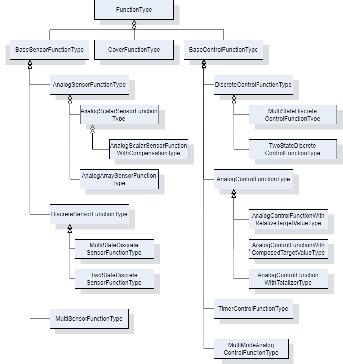
7.4.2 FunctionType ObjectType Definition
The FunctionType provides an abstract function type. It is formally defined in Table 78.
| Attribute | Value | ||||
| BrowseName | FunctionType | ||||
| IsAbstract | True | ||||
| References | Node Class | BrowseName | DataType | TypeDefinition | Other |
|---|---|---|---|---|---|
| Subtype of the TopologyElementType defined in OPC 10000-100 | |||||
| 0:HasComponent | Object | Configuration | 1:FunctionalGroupType | O | |
| 0:HasComponent | Object | FunctionSet | FunctionSetType | O | |
| 0:HasProperty | Variable | IsEnabled | Boolean | 0:PropertyType | M |
| Conformance Units | |||||
|---|---|---|---|---|---|
| LADS FunctionType | |||||
Configuration is used to organize parameters for configuration of the Function.
FunctionSet contains sub-functions of the Function.
IsEnabled indicates whether the Function can currently be executed on the Device. A Function may be disabled for several reasons including not licensed, missing hardware modules, or missing supplies.
7.5 Sensor Functions
7.5.1 BaseSensorFunctionType ObjectType Definition
The BaseSensorFunctionType is an abstract ObjectType used as a base for derivation of Sensor Functions. A Sensor Function is a Function that measures data. In LADS this is mainly data from the physical domain, but other domains are not excluded. In addition to the FunctionType, the Operational and Tuning FunctionalGroups were added for operational/tuneable Parameters and Methods. Furthermore, an AlarmMonitor of the Type ExclusiveLevelAlarm was added to observe unusual conditions in the measured data.
The ParameterSet was specialized to hold Parameters of the BaseSensorFunctionType.
The BaseSensorFunctionType is formally defined in Table 79.
| Attribute | Value | ||||
| BrowseName | BaseSensorFunctionType | ||||
| IsAbstract | True | ||||
| References | Node Class | BrowseName | DataType | TypeDefinition | Other |
|---|---|---|---|---|---|
| Subtype of the FunctionType defined in 7.4 | |||||
| Conformance Units | |||||
|---|---|---|---|---|---|
| LADS BaseSensorFunctionType | |||||
7.5.2 AnalogSensorFunctionType ObjectType Definition
The AnalogSensorFunctionType is an abstract subtype of the BaseSensorFunctionType which represents analogue measured values. The AnalogSensorFunctionType is formally defined in Table 80.
| Attribute | Value | ||||
| BrowseName | AnalogSensorFunctionType | ||||
| IsAbstract | True | ||||
| References | Node Class | BrowseName | DataType | TypeDefinition | Other |
|---|---|---|---|---|---|
| Subtype of the BaseSensorFunctionType defined in 7.5.1 | |||||
| 0:HasComponent | Object | AlarmMonitor | ExclusiveLevelAlarmType | O | |
| 0:HasComponent | Variable | RawValue | Double{Any} | AnalogUnitRangeType | M |
| 0:HasComponent | Variable | SensorValue | Double{Any} | AnalogUnitRangeType | M |
| 0:HasComponent | Object | Calibration | 1:FunctionalGroupType | O | |
| 0:HasComponent | Variable | CalibrationValues | Double[] | BaseDataVariableType | O |
| 0:HasProperty | Variable | Damping | Double | 0:PropertyType | O |
| 0:HasComponent | Object | Operational | 1:FunctionalGroupType | M | |
| 0:HasComponent | Object | Tuning | 1:FunctionalGroupType | O | |
| Conformance Units | |||||
|---|---|---|---|---|---|
| LADS AnalogSensorFunctionType | |||||
AlarmMonitor indicates whether the limit of an analogue Sensor is exceeded. See: 10000-9: Alarms & Conditions | ExclusiveLevelAlarmType.
RawValue is the raw value measured at the Sensor element, such as the Nernst voltage of a pH Sensor element.
SensorValue is the calibrated and optionally compensated/filtered process value.
Calibration is used to organize parameters for configuration of this Function.
CalibrationValues is an array of calibration values for converting the Sensor's raw value to the process value.
Damping is a low-pass filter parameter used for signal damping.
Operational is used to organize parameters for operation of this Function.
Tuning is used to organize parameters for operation of this Function.
7.5.3 AnalogArraySensorFunctionType ObjectType Definition
The AnalogArraySensorFunctionType is a concrete subtype of the AnalogSensorFunctionType which represents an array of analogue measured values. This is an extension point for all analogue measured values without built-in compensation on the Sensor. The AnalogArraySensorFunctionType is formally defined in Table 81.
| Attribute | Value | ||||
| BrowseName | AnalogArraySensorFunctionType | ||||
| IsAbstract | False | ||||
| References | Node Class | BrowseName | DataType | TypeDefinition | Other |
|---|---|---|---|---|---|
| Subtype of the AnalogSensorFunctionType defined in 7.5.2 | |||||
| 0:HasComponent | Variable | RawValue | Double{OneOrMoreDimensions} | AnalogUnitRangeType | M |
| 0:HasComponent | Variable | SensorValue | Double{OneOrMoreDimensions} | AnalogUnitRangeType | M |
| Conformance Units | |||||
|---|---|---|---|---|---|
| LADS AnalogArraySensorFunctionType | |||||
RawValue is the raw value measured at the Sensor element, such as the Nernst voltage of a pH Sensor element.
SensorValue is the calibrated and optionally compensated/filtered process value.
7.5.4 AnalogScalarSensorFunctionType ObjectType Definition
The AnalogScalarSensorFunctionType is a concrete subtype of the AnalogSensorFunctionType which represents an analogue measured value. This is an extension point for all analogue measured values without built-in compensation on the Sensor. The AnalogScalarSensorFunctionType is formally defined in Table 81.
| Attribute | Value | ||||
| BrowseName | AnalogScalarSensorFunctionType | ||||
| IsAbstract | False | ||||
| References | Node Class | BrowseName | DataType | TypeDefinition | Other |
|---|---|---|---|---|---|
| Subtype of the AnalogSensorFunctionType defined in 7.5.2 | |||||
| 0:HasComponent | Variable | RawValue | Double | AnalogUnitRangeType | M |
| 0:HasComponent | Variable | SensorValue | Double | AnalogUnitRangeType | M |
| Conformance Units | |||||
|---|---|---|---|---|---|
| LADS AnalogScalarSensorFunctionType | |||||
RawValue is the raw value measured at the Sensor element, such as the Nernst voltage of a pH Sensor element.
SensorValue is the calibrated and optionally compensated/filtered process value.
7.5.5 AnalogScalarSensorFunctionWithCompensationType ObjectType Definition
The AnalogScalarSensorFunctionWithCompensationType is a concrete subtype of the AnalogScalarSensorFunctionType which represents a measured value with compensation. This is an extension point for all analogue measured values with built-in compensation on the Sensor. The AnalogScalarSensorFunctionWithCompensationType is formally defined in Table 83.
| Attribute | Value | ||||
| BrowseName | AnalogScalarSensorFunctionWithCompensationType | ||||
| IsAbstract | False | ||||
| References | Node Class | BrowseName | DataType | TypeDefinition | Other |
|---|---|---|---|---|---|
| Subtype of the AnalogScalarSensorFunctionType defined in 7.5.4 | |||||
| 0:HasComponent | Variable | CompensationValue | Double | AnalogUnitRangeType | M |
| Conformance Units | |||||
|---|---|---|---|---|---|
| LADS AnalogScalarSensorFunctionWithCompensationType | |||||
CompensationValue is the compensation value used while calculating the process value, such as the temperature at the Sensor element for pH or DO Sensors.
7.5.6 DiscreteSensorFunctionType ObjectType Definition
The DiscreteSensorFunctionType is an abstract subtype of the base SensorFunctionType which represents a discrete measured value. It is formally defined in Table 84.
| Attribute | Value | ||||
| BrowseName | DiscreteSensorFunctionType | ||||
| IsAbstract | True | ||||
| References | Node Class | BrowseName | DataType | TypeDefinition | Other |
|---|---|---|---|---|---|
| Subtype of the BaseSensorFunctionType defined in 7.5.1 | |||||
| 0:HasComponent | Variable | SensorValue | BaseDataType | DiscreteItemType | M |
| 0:HasComponent | Object | Operational | 1:FunctionalGroupType | M | |
| Conformance Units | |||||
|---|---|---|---|---|---|
| LADS DiscreteSensorFunctionType | |||||
SensorValue is a discrete process value.
Operational is used to organize parameters for operation of this Function.
7.5.7 TwoStateDiscreteSensorFunctionType ObjectType Definition
The TwoStateDiscreteSensorFunctionType represents a Boolean value that is measured by a Sensor. It is formally defined in Table 85.
| Attribute | Value | ||||
| BrowseName | TwoStateDiscreteSensorFunctionType | ||||
| IsAbstract | False | ||||
| References | Node Class | BrowseName | DataType | TypeDefinition | Other |
|---|---|---|---|---|---|
| Subtype of the DiscreteSensorFunctionType defined in 7.5.1 | |||||
| 0:HasComponent | Variable | SensorValue | 0:Boolean | TwoStateDiscreteType | M |
| Conformance Units | |||||
|---|---|---|---|---|---|
| LADS TwoStateDiscreteSensorFunctionType | |||||
SensorValue a Boolean sensor value representing one of two discrete states.
7.5.8 MultiStateDiscreteSensorFunctionType ObjectType Definition
The MultiStateDiscreteSensorFunctionType represents a value that is measured by a Sensor and can only be set to a discrete set of values. It is formally defined in Table 86.
| Attribute | Value | ||||
| BrowseName | MultiStateDiscreteSensorFunctionType | ||||
| IsAbstract | False | ||||
| References | Node Class | BrowseName | DataType | TypeDefinition | Other |
|---|---|---|---|---|---|
| Subtype of the DiscreteSensorFunctionType defined in 7.5.1 | |||||
| 0:HasComponent | Variable | SensorValue | 0:UInt32 | MultiStateDiscreteType | M |
| Conformance Units | |||||
|---|---|---|---|---|---|
| LADS MultiStateDiscreteSensorFunctionType | |||||
SensorValue a UInt:32 sensore representing one out of multiple discrete states.
7.5.9 MultiSensorFunctionType ObjectType Definition
The MultiSensorFunctionType is a concrete subtype of the BaseSensorFunctionType which represents complex detectors with multiple sensors targeting a specific measurement task, e.g. diode array detector of a HPLC system.The specific sensor elements are represented by sensor-functions in the FunctionSet. The MultiSensorFunctionType is formally defined in Table 87.
| Attribute | Value | ||||
| BrowseName | MultiSensorFunctionType | ||||
| IsAbstract | False | ||||
| References | Node Class | BrowseName | DataType | TypeDefinition | Other |
|---|---|---|---|---|---|
| Subtype of the BaseSensorFunctionType defined in 7.5.1 | |||||
| 0:HasComponent | Object | FunctionSet | FunctionSetType | M | |
| Conformance Units | |||||
|---|---|---|---|---|---|
| LADS MultiSensorFunctionType | |||||
FunctionSet contains the sensor-functions of the different sensor elements.
7.6 Control Functions
7.6.1 BaseControlFunctionType ObjectType Definition
The BaseControlFunctionType provides an abstract superclass for all control functions. It is formally defined in Table 88.
| Attribute | Value | ||||
| BrowseName | BaseControlFunctionType | ||||
| IsAbstract | True | ||||
| References | Node Class | BrowseName | DataType | TypeDefinition | Other |
|---|---|---|---|---|---|
| Subtype of the FunctionType defined in7.4.2 | |||||
| 0:HasComponent | Object | AlarmMonitor | 0:ExclusiveDeviationAlarmType | O | |
| 0:HasComponent | Object | ControllerTuningParameter | ControllerTuningParameterType | O | |
| 0:HasComponent | Object | Operational | 1:FunctionalGroupType | M | |
| 0:HasComponent | Object | ControlFunctionState | ControlFunctionStateMachineType | M | |
| Conformance Units | |||||
|---|---|---|---|---|---|
| LADS BaseControlFunctionType | |||||
AlarmMonitor indicates whether the deviation from a set point exceeds the limit. See: 10000-9: Alarms & Conditions | ExclusiveDeviationAlarmType.
ControllerTuningParameter contains information on the Controller configuration. For example, the K factor of a PID control.
Operational is a FunctionalGroup that shall organize the CurrentState property of the ControlFunctionState StateMachine and all its remote invocable Methods. Furthermore, it shall organize at least the CurrentValue and TargetValue Properties found in the ParameterSet Object. Additional references to Properties or Methods within the scope of this Object are at the implementor's discretion (e.g., AlarmMonitor Properties).
ControlFunctionState is a state machine which represents the execution state and controls the execution of the Function.
7.6.2 ControlFunctionStateMachineType Definition
7.6.2.1 Overview
The ControlFunctionStateMachineType represents the state of a Function in a LADS Device. It uses the same StateTypes and TransitionTypes as its parent but specifies the additional Start Method to trigger state changes.
The ControlFunctionStateMachineType is formally defined in Table 89.
| Attribute | Value | ||||
| BrowseName | ControlFunctionStateMachineType | ||||
| IsAbstract | False | ||||
| References | Node Class | BrowseName | DataType | TypeDefinition | Other |
|---|---|---|---|---|---|
| Subtype of the FunctionalStateMachineType defined in 7.1.5 | |||||
| 0:HasComponent | Method | Start | O | ||
| 0:HasComponent | Method | StartWithTargetValue | O | ||
| Conformance Units | |||||
|---|---|---|---|---|---|
| LADS ControlFunctionStateMachineType | |||||
Start starts a Function on the LADS Device.
7.6.2.2 Start
The Start Method starts a Function on the LADS Device.
The signature of this Method is specified below. Table 90 specifies its representation in the AddressSpace.
Signature
Start()| Attribute | Value | ||||
| BrowseName | Start | ||||
| References | Node Class | BrowseName | DataType | TypeDefinition | ModellingRule |
|---|---|---|---|---|---|
7.6.2.3 StartWithTargetValue
The StartWithTargetValue Method starts a Function on the LADS Device with the target value as an argument.
Table 92 specify the Arguments and AddressSpace representation, respectively.
Signature
	StartWithTargetValue (
[in] Number TargetValue)| Argument | Description |
| TargetValue | (Optional) This value can be used to set the target value parallel with the start method. |
| Attribute | Value | ||||
| BrowseName | StartWithTargetValue | ||||
| References | Node Class | BrowseName | DataType | TypeDefinition | ModellingRule |
|---|---|---|---|---|---|
| 0:HasProperty | Variable | 0:InputArguments | 0:Argument[] | 0:PropertyType | M |
7.6.3 ControllerTuningParameterType Definition
The ControllerTuningParameterType is an abstract class. It is formally defined in Table 93. Subtypes of the ControllerTuningParameterType contain the parameters and information about a Controller (configuration).
| Attribute | Value | ||||
| BrowseName | ControllerTuningParameterType | ||||
| IsAbstract | False | ||||
| References | Node Class | BrowseName | DataType | TypeDefinition | Other |
|---|---|---|---|---|---|
| Subtype of the BaseObjectType defined in OPC 10000-5 | |||||
| Conformance Units | |||||
| LADS ControllerTuningParameterType | |||||
7.6.4 PidControllerParameterType Definition
The PidControllerParameterType contains the parameters of an PID controller. It is formally defined in Table 94.
| Attribute | Value | ||||
| BrowseName | PidControllerParameterType | ||||
| IsAbstract | False | ||||
| References | Node Class | BrowseName | DataType | TypeDefinition | Other |
|---|---|---|---|---|---|
| Subtype of the ControllerTuningParameterType defined in 7.6.2 | |||||
| HasComponent | Variable | CtrlP | Double | AnalogUnitRangeType | O |
| HasComponent | Variable | CtrlTd | Double | AnalogUnitRangeType | O |
| HasComponent | Variable | CtrlTi | Double | AnalogUnitRangeType | O |
| Conformance Units | |||||
|---|---|---|---|---|---|
| LADS PidControllerParameterType | |||||
CtrlP is the proportional controller parameter.
CtrlTd is the derivate controller parameter.
CtrlTi is the integrator controller parameter.
7.6.5 AnalogControlFunctionType ObjectType Definition
The AnalogControlFunctionType describes an analogue control function (using analogue values). In addition to the LADS BaseControlFunctionType, the ParameterSet has been made Mandatory. More specialized analogue control functions can be derived from this ObjectType. The AnalogControlFunctionType is formally defined in Table 95.
| Attribute | Value | ||||
| BrowseName | AnalogControlFunctionType | ||||
| IsAbstract | False | ||||
| References | Node Class | BrowseName | DataType | TypeDefinition | Other |
|---|---|---|---|---|---|
| Subtype of the BaseControlFunctionType defined in 7.6.1 | |||||
| 0:HasComponent | Variable | CurrentValue | 0:Double | AnalogUnitRangeType | M |
| 0:HasComponent | Variable | TargetValue | 0:Double | AnalogUnitRangeType | M |
| Conformance Units | |||||
|---|---|---|---|---|---|
| LADS AnalogControlFunctionType | |||||
CurrentValue is the current process value.
TargetValue is the targeted set-point value.
| BrowsePath | References | NodeClass | BrowseName | DataType | TypeDefinition | Others |
| ControlFunctionState | HasComponent | Method | StartWithTargetValue | O |
7.6.5.1 StartWithTargetValue
The StartWithTargetValue Method starts a Function on the LADS Device with the target value as an argument.
Table 92 specify the Arguments and AddressSpace representation, respectively.
Signature
	StartWithTargetValue (
[in] Double TargetValue)| Argument | Description |
| TargetValue | (Optional) This value can be used to set the target value parallel with the start method. |
| Attribute | Value | ||||
| BrowseName | StartWithTargetValue | ||||
| References | Node Class | BrowseName | DataType | TypeDefinition | ModellingRule |
|---|---|---|---|---|---|
| 0:HasProperty | Variable | 0:InputArguments | 0:Argument[] | 0:PropertyType | M |
7.6.6 AnalogControlFunctionWithComposedTargetValueType ObjectType Definition
The AnalogControlFunctionWithComposedTargetValueType describes an analogue control function (using analogue values), but the TargetValue is composed of several partial values.
An example of a composed target value used in mechanical stress analysers involves combining a static/constant base value with periodically changing values for defined amplitude, frequency, and waveform.
As the TargetValue is calculated from variables in the TargetValueSet, it should be read-only.
The AnalogControlFunctionWithComposedTargetValueType is formally defined in Table 99.
| Attribute | Value | ||||
| BrowseName | AnalogControlFunctionWithComposedTargetValueType | ||||
| IsAbstract | False | ||||
| References | Node Class | BrowseName | DataType | TypeDefinition | Other |
|---|---|---|---|---|---|
| Subtype of the AnalogControlFunctionType defined in 7.6.5 | |||||
| 0:HasComponent | Object | TargetValueSet | VariableSetType | M | |
| Conformance Units | |||||
|---|---|---|---|---|---|
| LADS AnalogControlFunctionWithComposedTargetValueType | |||||
TargetValueSet contains the partial values for the target value.
7.6.7 AnalogControlFunctionWithRelativeTargetValueType Definition
7.6.7.1 Overview
The AnalogControlFunctionWithRelativeTargetValueType supports applications where the target value is typically modified by relative increments or decrements.
Examples of its usage include position controllers where the actuator needs to modify its position relative to the last defined position by a specific amount, or dispenser controllers that are responsible for aspirating or dispensing a certain volume of fluid.
The optional DecreaseRate and IncreaseRate variables can be utilized to customize the dynamics of the resulting action based on application-specific requirements. These variables allow for adapting to factors such as viscosity when aspirating or dispensing fluids.
AnalogControlFunctionWithRelativeTargetValueType is formally defined in Table 100.
| Attribute | Value | ||||
| BrowseName | AnalogControlFunctionWithRelativeTargetValueType | ||||
| IsAbstract | False | ||||
| References | Node Class | BrowseName | DataType | TypeDefinition | Other |
|---|---|---|---|---|---|
| Subtype of the AnalogControlFunctionType defined in 7.6.5 | |||||
| 0:HasComponent | Variable | DecreaseRate | Double | AnalogUnitRangeType | O |
| 0:HasComponent | Method | ModifyTargetValueBy | O | ||
| 0:HasComponent | Variable | IncreaseRate | Double | AnalogUnitRangeType | O |
| Conformance Units | |||||
|---|---|---|---|---|---|
| LADS AnalogControlFunctionWithRelativeTargetValueType | |||||
7.6.7.2 ModifyTargetValueBy
The ModifyTargetValueBy Method is used to modify the current TargetValue by a relative amount. The resulting value shall be limited to the TargetValue's allowed range (EURange).
The direction of the action is application dependent and is controlled by the sign of the provided value. For instance, negative values may indicate moving left and positive values may indicate moving right, or positive values may be used for aspirating a defined volume while negative values may be used for dispensing a defined volume.
The signature of this Method is specified below. Table 101 and Table 102 specify the Arguments and AddressSpace representation, respectively.
Signature
	ModifyTargetValueBy (
		[in]	0:Double	Value
)| Argument | Description |
| Value | Relative value by which the target value will be changed. The resulting value will typically be limited to the target-value's allowed range. Provided values can be positive or negative. |
| Attribute | Value | ||||
| BrowseName | ModifyTargetValueBy | ||||
| References | Node Class | BrowseName | DataType | TypeDefinition | ModellingRule |
|---|---|---|---|---|---|
| 0:HasProperty | Variable | 0:InputArguments | 0:Argument[] | 0:PropertyType | 0:Mandatory |
7.6.8 AnalogControlFunctionWithTotalizerType ObjectType Definition
7.6.8.1 Overview
The AnalogControlFunctionWithTotalizerType describes an analogue control (using analogue values) function with totalizer.
Typical usage examples include but are not limited to fluid controllers where the quantity of fluid needs to be accurately measured and totalled for metering purposes.
AnalogControlFunctionWithTotalizerType is formally defined in Table 103.
| Attribute | Value | ||||
| BrowseName | AnalogControlFunctionWithTotalizerType | ||||
| IsAbstract | False | ||||
| References | Node Class | BrowseName | DataType | TypeDefinition | Other |
|---|---|---|---|---|---|
| Subtype of the AnalogControlFunctionType defined in 7.6.5 | |||||
| 0:HasComponent | Method | ResetTotalizer | O | ||
| 0:HasComponent | Variable | TotalizedValue | Double | AnalogUnitRangeType | M, RO |
| Conformance Units | |||||
|---|---|---|---|---|---|
| LADS AnalogControlFunctionWithTotalizerType | |||||
ResetTotalizer resets the totalizer to a specific value, or to zero if no input value is specified.
TotalizedValue is the totalized process value. It can be reset at any time using the ResetTotalizer() command.
7.6.8.2 ResetTotalizer
The ResetTotalizer Method resets the totalizer to a specific value, or to zero if no input value is specified. The signature of this Method is specified below. Table 104 and Table 105 specify the Arguments and AddressSpace representation, respectively.
Signature
	ResetTotalizer (
		[in] 	0:Double value
)| Argument | Description |
| Value | Relative value by which the target value will be changed. The resulting value will typically be limited to the target-value's allowed range. Provided values can be positive or negative. |
| Attribute | Value | ||||
| BrowseName | ResetTotalizer | ||||
| References | Node Class | BrowseName | DataType | TypeDefinition | ModellingRule |
|---|---|---|---|---|---|
| 0:HasProperty | Variable | 0:InputArguments | 0:Argument[] | 0:PropertyType | 0:Mandatory |
7.6.9 MultiModeAnalogControlFunctionType ObjectType Definition
The MultiModeAnalogControlFunctionType is used when a controller or actuator can be operated in different modes, depending on how the target value and current value are represented.
A common example in the laboratory and analytical domain is a peristaltic pump. In this case, the user can choose from various operation modes, such as relative pump speed (0 to 100%), absolute pump rotor speed in RPM, volumetric rate in mL/min (requiring pump calibration), or mass flow rate in g/min (requiring knowledge of the fluid density).
Another example in the laboratory and analytical domain is centrifuges. Operators can select between RPM or RCF (Rotational Centrifugal Force, defined as a multiple of G-force) modes. The RCF mode considers the radius of the centrifuge rotor when converting RCF to RPM.
When the centrifuge is operated in RCF mode, the RPM target value for the motor controller is calculated based on the RCF target value, while the reported RCF current value is calculated using the inverse function based on the measured rotation speed:
Centrifuge.RPM.TargetValue = f(Centrifuge.RCF.TargetValue, Radius)
Centrifuge.RCF.CurrentValue = f -1 (Centrifuge.RPM.CurrentValue, Radius)
As shown, a sequence of simple (typically bijective) mathematical equations can be used to convert between the target and current values of different modes. For example, linear functions are used in the pump example, while quadratic functions are used in the centrifuge example.
Essentially, the MultiModeAnalogControlFunctionType is modelled utilizing one common state machine with its methods to control the operation of the underlying resource (inherited from BaseControlFunctionType), a set of target/current value pairs, and a variable that allows the selection of the currently commanding mode.
The MultiModeAnalogControlFunctionType is formally defined in Table 95.
| Attribute | Value | ||||
| BrowseName | MultiModeAnalogControlFunctionType | ||||
| IsAbstract | False | ||||
| References | Node Class | BrowseName | DataType | TypeDefinition | Other |
|---|---|---|---|---|---|
| Subtype of the BaseControlFunctionType defined in 7.6.1 | |||||
| 0:HasComponent | Object | ControllerModeSet | ControllerParameterSetType | M | |
| 0:HasComponent | Variable | CurrentMode | 0:UInt32 | 0:MultiStateDiscreteType | M, RW |
| Conformance Units | |||||
|---|---|---|---|---|---|
| LADS MultiModeAnalogControlFunctionType | |||||
ControllerModeSet is the set of target/current value pairs.
CurrentMode defines the currently selected mode. Its EnumStrings array lists the different defined modes, which shall match the names of the corresponding elements in the ControllerModeSet.
7.6.10 ControllerParameterType ObjectType Definition
The ControllerParameterType represents a pair of target and current value variables for a specific mode of the MultiModeAnalogControlFunction (which typically have the same engineering unit).
| Attribute | Value | ||||
| BrowseName | ControllerParameterType | ||||
| IsAbstract | False | ||||
| References | Node Class | BrowseName | DataType | TypeDefinition | Other |
|---|---|---|---|---|---|
| Subtype of the BaseObjectType defined in OPC 10000-5 | |||||
| 0:HasComponent | Object | AlarmMonitor | 0:ExclusiveDeviationAlarmType | O | |
| 0:HasComponent | Variable | CurrentValue | 0:Double | 0:AnalogUnitRangeType | M, R |
| 0:HasComponent | Variable | TargetValue | 0:Double | 0:AnalogUnitRangeType | M, RW |
| Conformance Units | |||||
|---|---|---|---|---|---|
| LADS ControllerParameterType | |||||
AlarmMonitor indicates whether the deviation from a setpoint exceeds the limit. See: 10000-9: Alarms & Conditions | ExclusiveDeviationAlarmType.
CurrentValue is the current process value.
TargetValue is the targeted set-point value.
7.6.11 DiscreteControlFunctionType ObjectType Definition
The DiscreteControlFunctionType describes a discrete control function (using discrete values). More specialized discrete control functions can be derived from this ObjectType. The DiscreteControlFunctionType is formally defined in Table 108.
| Attribute | Value | ||||
| BrowseName | DiscreteControlFunctionType | ||||
| IsAbstract | True | ||||
| References | Node Class | BrowseName | DataType | TypeDefinition | Other |
|---|---|---|---|---|---|
| Subtype of the BaseControlFunctionType defined in 7.6.1 | |||||
| 0:HasComponent | Variable | CurrentValue | BaseDataType | DiscreteItemType | M |
| 0:HasComponent | Variable | TargetValue | BaseDataType | DiscreteItemType | M |
| Conformance Units | |||||
|---|---|---|---|---|---|
| LADS DiscreteControlFunctionType | |||||
CurrentValue is a current discrete process value.
TargetValue is the targeted set-point value.
7.6.12 MultiStateDiscreteControlFunctionType ObjectType Definition
The MultiStateDiscreteControlFunctionType describes a discrete control function (using more than two discrete values). It is formally defined in Table 109.
| Attribute | Value | ||||
| BrowseName | MultiStateDiscreteControlFunctionType | ||||
| IsAbstract | False | ||||
| References | Node Class | BrowseName | DataType | TypeDefinition | Other |
|---|---|---|---|---|---|
| Subtype of the DiscreteControlFunctionType defined in 7.6.1 | |||||
| 0:HasComponent | Variable | CurrentValue | UInt32 | MultiStateDiscreteType | M |
| 0:HasComponent | Variable | TargetValue | UInt32 | MultiStateDiscreteType | M |
| Conformance Units | |||||
|---|---|---|---|---|---|
| LADS MultiStateDiscreteControlFunctionType | |||||
| BrowsePath | References | NodeClass | BrowseName | DataType | TypeDefinition | Others |
| ControlFunctionState | HasComponent | Method | StartWithTargetValue | O |
7.6.12.1 StartWithTargetValue
The StartWithTargetValue Method starts a Function on the LADS Device with the target value as an argument.
Table 92 specify the Arguments and AddressSpace representation, respectively.
Signature
	StartWithTargetValue (
[in] UInt32 TargetValue)| Argument | Description |
| TargetValue | (Optional) This value can be used to set the target value parallel with the start method. |
| Attribute | Value | ||||
| BrowseName | StartWithTargetValue | ||||
| References | Node Class | BrowseName | DataType | TypeDefinition | ModellingRule |
|---|---|---|---|---|---|
| 0:HasProperty | Variable | 0:InputArguments | 0:Argument[] | 0:PropertyType | M |
7.6.13 TwoStateDiscreteControlFunctionType ObjectType Definition
The TwoStateDiscreteControlFunctionType describes a discrete control function with two possible values (e.g., on/off). It is formally defined in Table 113.
| Attribute | Value | ||||
| BrowseName | TwoStateDiscreteControlFunctionType | ||||
| IsAbstract | False | ||||
| References | Node Class | BrowseName | DataType | TypeDefinition | Other |
|---|---|---|---|---|---|
| Subtype of the DiscreteControlFunctionType defined in 7.6.7 | |||||
| 0:HasComponent | Variable | CurrentValue | Boolean | TwoStateDiscreteType | M |
| 0:HasComponent | Variable | TargetValue | Boolean | TwoStateDiscreteType | M |
| Conformance Units | |||||
|---|---|---|---|---|---|
| LADS TwoStateDiscreteControlFunctionType | |||||
| BrowsePath | References | NodeClass | BrowseName | DataType | TypeDefinition | Others |
| ControlFunctionState | HasComponent | Method | StartWithTargetValue | O |
7.6.13.1 StartWithTargetValue
The StartWithTargetValue Method starts a Function on the LADS Device with the target value as an argument.
Table 92 specify the Arguments and AddressSpace representation, respectively.
Signature
	StartWithTargetValue (
[in] Boolean TargetValue)| Argument | Description |
| TargetValue | (Optional) This value can be used to set the target value parallel with the start method. |
| Attribute | Value | ||||
| BrowseName | StartWithTargetValue | ||||
| References | Node Class | BrowseName | DataType | TypeDefinition | ModellingRule |
|---|---|---|---|---|---|
| 0:HasProperty | Variable | 0:InputArguments | 0:Argument[] | 0:PropertyType | M |
7.6.14 TimerControlFunctionType ObjectType Definition
The TimerControlFunctionType defines a simple "one shot" Timer which stops once it has elapsed. It follows the design of other LADS ControlFunctions, utilizing the same state machine and similar variable definitions. The TimerFunctionType is formally defined in Table 117.
Once started, the CurrentValue counts upwards from zero until it reaches the TargetValue.
The DifferenceValue is calculated by subtracting the CurrentValue from the TargetValue. Thus, it counts downwards from the TargetValue to zero.
As soon as the CurrentValue reaches the TargetValue, the CurrentState of the TimerFunction automatically transitions to Off. This is typically accompanied by some (internal) action/effect, such as stopping the execution of a Function or similar.
In the SuspendedState the CurrentValue holds its current value and does not count further until the state switches back to On, either due to a Client command or an internal state change.
| Attribute | Value | ||||
| BrowseName | TimerControlFunctionType | ||||
| IsAbstract | False | ||||
| References | Node Class | BrowseName | DataType | TypeDefinition | Other |
|---|---|---|---|---|---|
| Subtype of the BaseControlFunctionType defined in 7.6.1 | |||||
| 0:HasComponent | Variable | CurrentValue | Duration | AnalogUnitRangeType | O |
| 0:HasComponent | Variable | DifferenceValue | Duration | AnalogUnitRangeType | O |
| 0:HasComponent | Variable | TargetValue | Duration | AnalogUnitRangeType | O |
| Conformance Units | |||||
|---|---|---|---|---|---|
| LADS TimerControlFunctionType | |||||
CurrentValue is the elapsed time in milliseconds since the Timer was started.
DifferenceValue is the remaining time in milliseconds until the Timer will be stopped.
TargetValue is the target time in milliseconds.
7.7 Other Functions
7.7.1 CoverFunctionType ObjectType Definition
The CoverFunctionType is used to control the cover, door, or lid of a Laboratory Device. In addition to the FunctionType, the Operational FunctionalGroup was added for operational Parameters and Methods. Additionally, CoverStateMachine was added to monitor/control the state of a Device. The CoverFunctionType is formally defined in Table 118.
| Attribute | Value | ||||
| BrowseName | CoverFunctionType | ||||
| IsAbstract | False | ||||
| References | Node Class | BrowseName | DataType | TypeDefinition | Other |
|---|---|---|---|---|---|
| Subtype of the FunctionType defined in 7.4 | |||||
| 0:HasComponent | Object | Operational | 1:FunctionalGroupType | M | |
| 0:HasComponent | Object | CoverState | CoverStateMachineType | M | |
| Conformance Units | |||||
|---|---|---|---|---|---|
| LADS CoverFunctionType | |||||
CoverState is a state machine which controls the cover of a LADS Device. See CoverStateMachineType for details about the controlling state machine.
7.7.2 CoverStateMachineType ObjectType Definition
7.7.2.1 Overview
The CoverStateMachineType is used to control the lid, door, or cover of a LADS Device. One Device may have any arbitrary number of lids, doors, covers and their corresponding CoverFunction. It is formally defined in Table 119.
The CoverStateMachine is depicted in Figure 19.
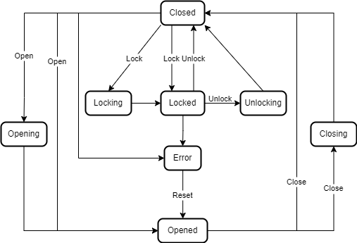
| Attribute | Value | ||||
| BrowseName | CoverStateMachineType | ||||
| IsAbstract | False | ||||
| References | Node Class | BrowseName | DataType | TypeDefinition | Other |
|---|---|---|---|---|---|
| Subtype of the FiniteStateMachineType defined in OPC 10000-5 | |||||
| 0:HasComponent | Method | Close | O | ||
| 0:HasComponent | Object | Closed | StateType | ||
| 0:HasComponent | Object | ClosedToError | TransitionType | ||
| 0:HasComponent | Object | ClosedToLocked | TransitionType | ||
| 0:HasComponent | Object | ClosedToLocking | TransitionType | ||
| 0:HasComponent | Object | ClosedToOpened | TransitionType | ||
| 0:HasComponent | Object | ClosedToOpening | TransitionType | ||
| 0:HasComponent | Object | Closing | StateType | ||
| 0:HasComponent | Object | ClosingToClosed | TransitionType | ||
| 0:HasComponent | Object | Error | StateType | ||
| 0:HasComponent | Object | ErrorToOpened | TransitionType | ||
| 0:HasComponent | Method | Lock | O | ||
| 0:HasComponent | Object | Locked | StateType | ||
| 0:HasComponent | Object | LockedToClosed | TransitionType | ||
| 0:HasComponent | Object | LockedToError | TransitionType | ||
| 0:HasComponent | Object | LockedToUnlocking | TransitionType | ||
| 0:HasComponent | Object | Locking | StateType | ||
| 0:HasComponent | Object | LockingToLocked | TransitionType | ||
| 0:HasComponent | Method | Open | O | ||
| 0:HasComponent | Object | Opened | StateType | ||
| 0:HasComponent | Object | OpenedToClosed | TransitionType | ||
| 0:HasComponent | Object | OpenedToClosing | TransitionType | ||
| 0:HasComponent | Object | Opening | StateType | ||
| 0:HasComponent | Object | OpeningToOpened | TransitionType | ||
| 0:HasComponent | Method | Reset | O | ||
| 0:HasComponent | Method | Unlock | O | ||
| 0:HasComponent | Object | Unlocking | StateType | ||
| 0:HasComponent | Object | UnlockingToClosed | TransitionType | ||
| Conformance Units | |||||
|---|---|---|---|---|---|
| LADS CoverStateMachineType | |||||
Close is a Optional Method that can be called in the Opened state to close the cover of the Device.
Closed is the state of the LADS Device cover when it is closed.
ClosedToError is triggered if the closed cover has a malfunction, such as on locking or opening.
ClosedToLocked is triggered if the closed cover is also locked. This can either be done manually on the Device or by calling the Lock Method remotely.
ClosedToLocking is triggered if the closed cover starts the process of closing. This can either be done manually on the Device or by calling the Lock Method remotely.
ClosedToOpened is triggered if the cover of the Device is opened. This can be done either manually or by calling the Open Method remotely.
ClosedToOpening is triggered in the process of opening the cover. This can be done either manually or by calling the Open Method remotely.
Closing is the transitive state of the LADS Device cover when it is in the process of closing.
ClosingToClosed is triggered if the cover has ended its process of closing and is finally closed.
Error is the state of the LADS Device cover when it is in an error state. For example, if the locking did not work properly or there is some kind of malfunction on locking/closing the Device cover.
ErrorToOpened is triggered if the cover recovers from an Error state. This can either be done manually or by calling the Reset Method.
Lock is a Optional Method that can be called from the Closed state to lock the cover of the Device.
Locked is the state of the LADS Device cover when it is closed and locked.
LockedToClosed is triggered if the locked cover is unlocked. This can either be done manually on the Device or by calling the Unlock Method remotely.
LockedToError is triggered if the locked cover has a malfunction, such as on unlocking.
LockedToUnlocking is triggered if the locked cover starts the process of unlocking. This can either be done manually on the Device or by calling the Unlock Method remotely.
Locking is the transitive state of the LADS Device cover when it is in the process of locking.
LockingToLocked is triggered if the cover has ended its locking process is finally locked.
Open is a Mandatory Method that can be called from the Closed state to open the cover of the Device.
Opened is the state of the LADS Device cover when it is opened.
OpenedToClosed is triggered if the cover of the Device is closed, either manually or by calling the Close Method remotely.
OpenedToClosing is triggered if the cover of the Device starts the process of closing, either manually or by calling the Close Method remotely.
Opening is the transitive state of the LADS Device cover when it is in the process of opening.
OpeningToOpened is triggered if the cover has ended its opening process is finally opened.
Unlock is a Optional Method that can be called from the Locked state to unlock the cover of the Device.
Unlocking is the transitive state of the LADS Device cover when it is in the process of unlocking.
UnlockingToClosed is triggered if the cover has ended its unlocking process is finally closed.
Reset is a Mandatory Method that can be called from the Error state to open the cover of the Device.
The children of the CoverStateMachineType have additional References, which are defined in Table 120.
| SourceBrowsePath | Reference Type | Is Forward | TargetBrowsePath |
| ClosedToError | 0:FromState | True | Closed |
| 0:ToState | True | Error | |
| 0:HasEffect | True | TransitionEventType | |
| ClosedToLocked | 0:FromState | True | Closed |
| 0:ToState | True | Locked | |
| 0:HasCause | True | Lock | |
| 0:HasEffect | True | TransitionEventType | |
| ClosedToLocking | 0:FromState | True | Closed |
| 0:ToState | True | Locking | |
| 0:HasCause | True | Lock | |
| ClosedToOpened | 0:FromState | True | Closed |
| 0:ToState | True | Opened | |
| 0:HasCause | True | Open | |
| 0:HasEffect | True | TransitionEventType | |
| ClosedToOpening | 0:FromState | True | Closed |
| 0:ToState | True | Opening | |
| 0:HasCause | True | Open | |
| ClosingToClosed | 0:FromState | True | Closing |
| 0:ToState | True | Closed | |
| ErrorToOpened | 0:FromState | True | Error |
| 0:ToState | True | Opened | |
| 0:HasCause | True | Reset | |
| 0:HasEffect | True | TransitionEventType | |
| LockedToClosed | 0:FromState | True | Locked |
| 0:ToState | True | Closed | |
| 0:HasCause | True | Unlock | |
| 0:HasEffect | True | TransitionEventType | |
| LockedToError | 0:FromState | True | Locked |
| 0:ToState | True | Error | |
| 0:HasEffect | True | TransitionEventType | |
| LockedToUnlocking | 0:FromState | True | Locked |
| 0:ToState | True | Unlocking | |
| 0:HasCause | True | Unlock | |
| LockingToLocked | 0:FromState | True | Locking |
| 0:ToState | True | Locked | |
| OpenedToClosed | 0:FromState | True | Opened |
| 0:ToState | True | Closed | |
| 0:HasCause | True | Close | |
| 0:HasEffect | True | TransitionEventType | |
| OpenedToClosing | 0:FromState | True | Opened |
| 0:ToState | True | Closing | |
| 0:HasCause | True | Close | |
| OpeningToOpened | 0:FromState | True | Opening |
| 0:ToState | True | Opened | |
| UnlockingToClosed | 0:FromState | True | Unlocking |
| 0:ToState | True | Closed |
The Component Variables of the CoverStateMachineType have additional Attributes, as defined in Table 121.
| BrowsePath | Value Attribute | ||
| 1 | ||
| 5 | ||
| 2 | ||
| 3 | ||
| 6 | ||
| 4 | ||
| 7 | ||
| 8 | ||
| 6 | ||
| 3 | ||
| 8 | ||
| 2 | ||
| 9 | ||
| 10 | ||
| 7 | ||
| 4 | ||
| 5 | ||
| 11 | ||
| 12 | ||
| 1 | ||
| 13 | ||
| 14 | ||
| 15 |
7.7.2.2 Close
The Close Method can be called in the Opened state to close the cover of the Device. The signature of this Method is specified below. Table 122 specifies its representation in the AddressSpace.
Signature
Close ()| Attribute | Value | ||||
| BrowseName | Close | ||||
| References | Node Class | BrowseName | DataType | TypeDefinition | ModellingRule |
|---|---|---|---|---|---|
7.7.2.3 Lock
The Lock Method can be called from the Closed state to lock the cover of the Device. The signature of this Method is specified below. Table 123 specifies its representation in the AddressSpace.
Signature
Lock ()| Attribute | Value | ||||
| BrowseName | Lock | ||||
| References | Node Class | BrowseName | DataType | TypeDefinition | ModellingRule |
|---|---|---|---|---|---|
7.7.2.4 Open
The Open Method can be called from the Closed state to open the cover of the Device. The signature of this Method is specified below. Table 124 specifies its representation in the AddressSpace.
Signature
Open ()| Attribute | Value | ||||
| BrowseName | Open | ||||
| References | Node Class | BrowseName | DataType | TypeDefinition | ModellingRule |
|---|
7.7.2.5 Reset
The Reset Method can be called from the Error state to open the cover of the Device. The signature of this Method is specified below. Table 125 specifies the Arguments and AddressSpace representation.
Signature
Reset ()| Attribute | Value | ||||
| BrowseName | Reset | ||||
| References | Node Class | BrowseName | DataType | TypeDefinition | ModellingRule |
|---|---|---|---|---|---|
7.7.2.6 Unlock
The Unlock Method can be called to unlock the cover. The signature of this Method is specified below. Table 126 specifies its representation in the AddressSpace.
Signature
Unlock ()| Attribute | Value | ||||
| BrowseName | Unlock | ||||
| References | Node Class | BrowseName | DataType | TypeDefinition | ModellingRule |
|---|