
7.1 Type for Devices, Components and FunctionalUnits
7.1.1 LADSDeviceType ObjectType Definition
The LADSDeviceType provides a base class for Laboratory and Analytical Devices. It is formally defined in Table 15.
| Attribute | Value | ||||
| BrowseName | LADSDeviceType | ||||
| IsAbstract | False | ||||
| References | Node Class | BrowseName | DataType | TypeDefinition | Other |
|---|---|---|---|---|---|
| Subtype of the DeviceType defined in OPC 10000-100 | |||||
| 0:HasAddIn | Object | 4:Components | LADSComponentsType | O | |
| 0:HasComponent | Object | FunctionalUnitSet | FunctionalUnitSetType | M | |
| 0:HasProperty | Variable | 3:HierarchicalLocation | 0:String | 0:PropertyType | O |
| 0:HasAddIn | Object | 2:Identification | 4:MachineIdentificationType | M | |
| 0:HasProperty | Variable | 3:OperationalLocation | 0:String | 0:PropertyType | O |
| 0:HasComponent | Object | DeviceState | LADSDeviceStateMachineType | M | |
| 0:HasComponent | Object | Maintenance | MaintenanceSetType | O | |
| 0:Organizes | Object | 4:MachineryBuildingBlocks | 0:FolderType | O | |
| 0:HasAddIn | Object | 4:MachineryItemState | 4:MachineryItemState_StateMachineType | O | |
| 0:HasAddIn | Object | 4:MachineryOperationMode | LADSOperationModeStateMachineType | O | |
| 0:HasAddIn | Object | 2:OperationCounters | 4:MachineryOperationCounterType | O | |
| 0:HasAddIn | Object | 4:LifetimeCounters | 4:MachineryLifetimeCounterType | O | |
| Conformance Units | |||||
|---|---|---|---|---|---|
| LADS LADSDeviceType | |||||
Components is a generic set of identifiable sub-components of the Device as mandated by OPC 40001-1.
FunctionalUnitSet contains the Functional Units of this Device.
HierarchicalLocation provides the hierarchical location of the LADS Device. The structure within the string may expose several levels. How this is exposed, which delimiters are used, etc. is vendor specific. Examples of such strings are "FactoryA/BuildingC/Floor1" or "Area1-ProcessCell17-Unit4" (see OPC UA OPC 10000-110 for more details).
OperationalLocation provides the operational location of the LADS Device. The structure within the string may expose several levels. How this is exposed, which delimiters are used, etc. is vendor specific. Examples of such strings are "Warehouse1/Sheet3" or "StainlessSteelTote3" (see OPC UA OPC 10000-110 for more details).
Recommendations for both hierarchical and operational locations have been proposed:
For instances where the location definition encompasses multiple levels, these levels should be separated by the delimiter character "/". An instance of a location definition with multiple levels separated by the delimiting character "/" is "US-NY-NYC-Building101/Floor35/Room10.1".
For additional use cases not covered by the aforementioned properties, it is recommended to employ the additional location formats NmeaCoordinateString, LocalCoordinate, and WGS84Coordinate as delineated in the OPC UA for AutoId Devices Release 1.01.1 (2021-07-13) specification.
Identification provides properties to identify a Device.
Recommendations for the Identification:
If the device consists solely of software with no hardware, the SoftwareRevision should be provided, and the HardwareRevision should be omitted.
If the device consists solely of hardware with no software, the HardwareRevision should be provided, and the SoftwareRevision should be omitted.
If the device consists of both hardware and software, the HardwareRevision should be provided. The SoftwareRevision should be provided if there are no device components providing a SoftwareRevision. Otherwise, the SoftwareRevision may be provided to represent the overall revision of all software components.
If a ProductInstanceUri can be created, this property should be part of the Identification.
OperationCounters for monitoring the operation of a LADSDeviceType, including parameters of the OperationCounters interface and lifetime variables (see OPC UA for Devices for more information).
DeviceState StateMachine that controls and represents the Device's current state.
Maintenance is a set containing all maintenance tasks of a Device.
The MachineryBuildingBlocks folder contains all machinery building blocks, especially the MachineryItemState, MachineryOperationMode, OperationCounter and Lifetime Counter.
Refer to Annex B for proposed mappings between the DeviceStateMachine, the FunctionalUnit state machines, the MachineryItemState and the DeviceHealth.
MachineryItemState indicates the current state of the device and is comparable with the LADS Device state machine.
MachineryOperationMode indicates the type of Tasks being performed by the Device.
OperationCounter provides information on how long a MachineryItem has been turned on and how long it performed an activity. It uses the 2:IOperationCounterType interface and the predefined functional group 2:OperationCounters defined in OPC 10000-100.
Lifetime Counter provides information about the past and estimated remaining lifetime of a MachineryItem, or other aspects of a MachineryItem such as a software license. It is based on the 2:LifetimeVariableType defined in OPC 10000-100.
Children of the LADSDeviceType have additional References, which are defined in Table 16.
| SourceBrowsePath | Reference Type | Is Forward | TargetBrowsePath | ||
| 4:MachineryBuildingBlocks | 0:HasAddIn | True |
| ||
| 4:MachineryBuildingBlocks | 0:HasAddIn | True |
| ||
| 4:MachineryBuildingBlocks | 0:HasAddIn | True |
| ||
| 4:MachineryBuildingBlocks | 0:HasAddIn | True |
| ||
| 4:MachineryBuildingBlocks | 0:HasAddIn | True |
| ||
| 4:MachineryBuildingBlocks | 0:HasAddIn | True |
|
7.1.2 LADSDeviceStateMachineType ObjectType Definition
7.1.2.1 Overview
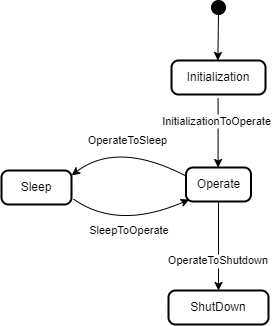
The LADSDeviceStateMachineType state machine represents the Device's current state. It is inspired by the AnalyserDeviceStateMachineType from the Analyzer Devices Specification.
The LADSDeviceStateMachine is depicted in Figure 15
The LADSDeviceStateMachineType is formally defined in Table 17.
| Attribute | Value | ||||
| BrowseName | LADSDeviceStateMachineType | ||||
| IsAbstract | False | ||||
| References | Node Class | BrowseName | DataType | TypeDefinition | Other |
|---|---|---|---|---|---|
| Subtype of the FiniteStateMachineType defined in OPC 10000-5 | |||||
| 0:HasComponent | Method | GotoOperate | O | ||
| 0:HasComponent | Method | GotoShutdown | O | ||
| 0:HasComponent | Method | GotoSleep | O | ||
| 0:HasComponent | Object | Operate | StateType | ||
| 0:HasComponent | Object | OperateToShutdown | TransitionType | ||
| 0:HasComponent | Object | OperateToSleep | TransitionType | ||
| 0:HasComponent | Object | Initialization | InitialStateType | ||
| 0:HasComponent | Object | InitializationToOperate | TransitionType | ||
| 0:HasComponent | Object | Shutdown | StateType | ||
| 0:HasComponent | Object | Sleep | StateType | ||
| 0:HasComponent | Object | SleepToOperate | TransitionType | ||
| Conformance Units | |||||
|---|---|---|---|---|---|
| LADS LADSDeviceStateMachineType | |||||
There are four Device states, as follows:
Initialization: The Device is in its initializing sequence and cannot perform any other Task.
Operate: The Device is in Operating mode. The LADS Client uses this mode for normal operation: configuration, control, and data collection.
Sleep: The Device is still powered on and its OPC UA Server is still running, but it is not ready to perform any Tasks until it transitions to the Operate state. This state can be used to represent a PowerSave state where a Device may shut down some of its Components, such as the GUI. It can also be used to represent a Sleep state, where a Device is running with minimal services but ready to be triggered to transition into the Operate state.
Shutdown: The Device is in its power-down sequence and cannot perform any other Task. Optionally, there are devices that can be powered off via physical means, especially simpler ones. The electronics are turned off immediately; therefore, such devices do not transition into a Shutdown state.
Note: Shutdown is the state in which the LADS Device waits for the completion of the power down sequence. Its sub-states are out of scope of the LADS specification.
Children of the LADSDeviceStateMachineType have additional References, which are defined in Table 18.
| SourceBrowsePath | Reference Type | Is Forward | TargetBrowsePath |
| InitializationToOperate | 0:FromState | True | Initialization |
| 0:ToState | True | Operate | |
| 0:HasEffect | True | TransitionEventType | |
| OperateToSleep | 0:FromState | True | Operate |
| 0:ToState | True | Sleep | |
| 0:HasCause | True | GotoSleep | |
| 0:HasEffect | True | TransitionEventType | |
| SleepToOperate | 0:FromState | True | Sleep |
| 0:ToState | True | Operate | |
| 0:HasCause | True | GotoOperate | |
| 0:HasEffect | True | TransitionEventType | |
| OperateToShutdown | 0:FromState | True | Operate |
| 0:ToState | True | Shutdown | |
| 0:HasCause | True | GotoShutdown | |
| 0:HasEffect | True | TransitionEventType |
The Component Variables of the LADSDeviceStateMachineType have additional Attributes, as defined in Table 19.
| BrowsePath | Value Attribute | ||
| 1 | ||
| 2 | ||
| 3 | ||
| 4 | ||
| 3 | ||
| 4 | ||
| 2 | ||
| 1 |
7.1.2.2 GotoOperate
The GotoOperate Method is used to set the Device into an operating mode. The signature of this Method is specified below. Table 20 specifies its representation in the AddressSpace.
Signature
GotoOperate ()| Attribute | Value | ||||
| BrowseName | GotoOperate | ||||
| References | Node Class | BrowseName | DataType | TypeDefinition | ModellingRule |
|---|
7.1.2.3 GotoShutdown
The GotoShutdown Method is used to shut down the Device. The signature of this Method is specified below. Table 21 specifies its representation in the AddressSpace.
Signature
GotoShutdown ()| Attribute | Value | ||||
| BrowseName | GotoShutdown | ||||
| References | Node Class | BrowseName | DataType | TypeDefinition | ModellingRule |
|---|---|---|---|---|---|
7.1.2.4 GotoSleep
The GotoSleep Method is used to set the Device to Sleep. The signature of this Method is specified below. Table 22 specifies its representation in the AddressSpace.
Signature
GotoSleep ()| Attribute | Value | ||||
| BrowseName | GotoSleep | ||||
| References | Node Class | BrowseName | DataType | TypeDefinition | ModellingRule |
|---|
7.1.3 LADSComponentType ObjectType Definition
Devices may be composed of tangible subcomponents. A Component is represented by the LADSComponentType. A Component itself may also have subcomponents. The LADSComponentType is formally defined in Table 23.
| Attribute | Value | ||||
| BrowseName | LADSComponentType | ||||
| IsAbstract | False | ||||
| References | Node Class | BrowseName | DataType | TypeDefinition | Other |
|---|---|---|---|---|---|
| Subtype of the 2:ComponentType defined in OPC 10000-100 | |||||
| 0:HasAddIn | Object | Components | LADSComponentsType | O | |
| 0:HasAddIn | Object | 2:Identification | M | ||
| 0:HasComponent | Object | Maintenance | MaintenanceSetType | O | |
| 0:HasProperty | Variable | 3:OperationalLocation | 0:String | 0:PropertyType | O |
| 0:HasProperty | Variable | 3:HierarchicalLocation | 0:String | 0:PropertyType | O |
| 0:Organizes | Object | 4:MachineryBuildingBlocks | 0:FolderType | O | |
| 0:HasAddIn | Object | 2:OperationCounters | 4:MachineryOperationCounterType | O | |
| 0:HasAddIn | Object | 4:LifetimeCounters | 4:MachineryLifetimeCounterType | O | |
| 0:HasInterface | ObjectType | 2:IDeviceHealthType | |||
| Applied from 2:IDeviceHealthType | |||||
| 0:HasComponent | Variable | 2:DeviceHealth | 2:DeviceHealthEnumeration | 0:BaseDataVariableType | O |
| 0:HasComponent | Object | 2:DeviceHealthAlarms | 0:FolderType | O | |
| Conformance Units | |||||
|---|---|---|---|---|---|
| LADS LADSComponentType | |||||
Components is a generic set of identifiable subcomponents of the device as mandated by OPC 40001-1.
Identification provides the properties to identify a device.
Recommendations for Identification:
• If the Component consists solely of software with no hardware, the SoftwareRevision should be provided and the HardwareRevision should be omitted.
• If the Component consists solely of hardware with no software, the HardwareRevision should be provided and the SoftwareRevision should be omitted.
• If the Component consists of both hardware and software, the HardwareRevision should be provided. The SoftwareRevision should be provided if there are no subcomponents providing a SoftwareRevision. Otherwise, the SoftwareRevision may be provided to represent the overall revision of all software components.
HierarchicalLocation provides the hierarchical location of the LADS Device. The structure inside the string may expose several levels. How this is exposed, which delimiters are used, etc. is vendor specific. Examples of such strings are "FactoryA/BuildingC/Floor1" or "Area1-ProcessCell17-Unit4" (see OPC 10000-110 for more Details).
OperationalLocation provides the operational location of the LADS Device. The structure within the string may expose several levels. How this is exposed, which delimiters are used, etc. is vendor specific. Examples of such strings are "Warehouse1/Sheet3" or "StainlessSteelTote3" (see OPC 10000-110 for more Details).
Recommendations for both hierarchical and operational locations have been proposed:
For instances where the location definition encompasses multiple levels, these levels should be separated by the delimiter character "/". An instance of a location definition with multiple levels separated by the delimiting character "/" is "US-NY-NYC-Building101/Floor35/Room10.1".
For additional use cases not covered by the aforementioned properties, it is recommended to employ the additional location formats NmeaCoordinateString, LocalCoordinate, and WGS84Coordinate as delineated in the OPC UA for AutoId Devices Release 1.01.1 (2021-07-13) specification.
DeviceHealth indicates the health status of a Device as defined by NAMUR Recommendation NE 107 (see OPC 10000-100 for more Details).
DeviceHealthAlarms groups all instances of Device health-related Alarms.
OperationCounters for monitoring the operation of a LADSDeviceType, including parameters of the OperationCounters interface and lifetime variables (see OPC 10000-100 for more information).
Maintenance is a set containing all maintenance tasks of a Device.
The MachineryBuildingBlocks folder contains all machinery building blocks, especially the OperationCounter, and Lifetime Counter.
OperationCounter provides information on how long a MachineryItem has been turned on and how long it performed an activity. It uses the 2:IOperationCounterType interface and the predefined functional group 2:OperationCounters defined in OPC 10000-100.
Lifetime Counter provides information about the past and estimated remaining lifetime of a MachineryItem, or other aspects of a MachineryItem such as a software license. It is based on the 2:LifetimeVariableType defined in OPC 10000-100.
Children of the LADSComponentsType have additional References, which are defined in Table 24.
| SourceBrowsePath | Reference Type | Is Forward | TargetBrowsePath | ||
| 4:MachineryBuildingBlocks | 0:HasAddIn | True |
| ||
| 4:MachineryBuildingBlocks | 0:HasAddIn | True |
| ||
| 4:MachineryBuildingBlocks | 0:HasAddIn | True |
|
7.1.4 FunctionalUnitType ObjectType Definition
The FunctionalUnitType represents a functional unit of a Laboratory or Analytical Device. It is formally defined in Table 25.
| Attribute | Value | ||||
| BrowseName | FunctionalUnitType | ||||
| IsAbstract | False | ||||
| References | Node Class | BrowseName | DataType | TypeDefinition | Other |
| Subtype of the TopologyElementType defined in OPC 10000-100 | |||||
| 0:HasComponent | Object | ProgramManager | ProgramManagerType | O | |
| 0:HasComponent | Object | FunctionalUnitState | FunctionalUnitStateMachineType | M | |
| 0:HasComponent | Object | SupportedPropertiesSet | SupportedPropertiesSetType | O | |
| 0:HasComponent | Object | FunctionSet | FunctionSetType | O | |
| 0:HasComponent | Object | Operational | 1:FunctionalGroupType | O | |
| 0:HasInterface | ObjectType | 2:ITagNameplateType | |||
| Implements the 2:ITagNameplateType | |||||
| 0:HasProperty | Variable | 2:AssetId | 0:String | 0:PropertyType | O |
| 0:HasProperty | Variable | 2:ComponentName | LocalizedText | 0:PropertyType | O |
| Conformance Units | |||||
| LADS FunctionalUnitType | |||||
AssetId is a user-writeable alphanumeric character sequence that uniquely identifies a FunctionalUnit (see OPC UA 10000-100).
ComponentName is a user-writeable name provided by the integrator or user of the FunctionalUnit.
FunctionSet contains the Functions of the FunctionalUnit.
Program Manager manages the programs and results of the FunctionalUnit.
FunctionalUnitState the StateMachine that is used for this FunctionalUnit.
Operational Functional Group that organizes Properties and Methods for this FunctionalUnit.
SupportedPropertiesSet provides references to variables of sub-ordinate Functions of the FunctionalUnit whose values can be specified as input Arguments when calling the FunctionalUnit.FunctionalUnitState.Start() or ProgramManager.ActiveProgram.StateMachine.Start() Methods.
7.1.5 FunctionalStateMachineType ObjectType Definition
7.1.5.1 Overview
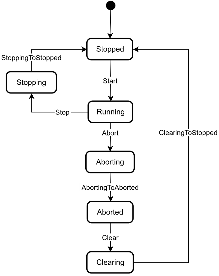
The FunctionalStateMachineType is the top level StateMachine for the LADS ActiveProgram, FunctionalUnit or Function. The basic idea behind this architecture is that the instances of the FunctionalStateMachineType, the ActiveProgramStateMachineType, the FunctionalUnitStateMachineType and the FunctionStateMachineType use the same states, Transitions and Methods, but add their own Start Methods with different Method Signatures to trigger the StoppedToRunning Transition from a Client.
The FunctionalStateMachineType defines the available states in a LADS system.
The FunctionalStateMachineType is formally defined in Table 26. StateTypes and TransitionTypes only exist in the type system, thus they do not have a modelling rule.
The FunctionalStateMachine is depicted in Figure 16.
| Attribute | Value | ||||
| BrowseName | FunctionalStateMachineType | ||||
| IsAbstract | True | ||||
| References | Node Class | BrowseName | DataType | TypeDefinition | Other |
|---|---|---|---|---|---|
| Subtype of the 0:FiniteStateMachineType defined in OPC 10000-5 | |||||
| 0:HasComponent | Variable | 0:AvailableTransitions | 0:NodeId[] | 0:BaseDataVariableType | M |
| 0:HasComponent | Variable | 0:AvailableStates | 0:NodeId[] | 0:BaseDataVariableType | M |
| 0:HasComponent | Method | Abort | O | ||
| 0:HasComponent | Object | Aborted | StateType | ||
| 0:HasComponent | Object | AbortedToClearing | TransitionType | ||
| 0:HasComponent | Object | Aborting | StateType | ||
| 0:HasComponent | Object | AbortingToAborted | TransitionType | ||
| 0:HasComponent | Method | Clear | O | ||
| 0:HasComponent | Object | Clearing | StateType | ||
| 0:HasComponent | Object | ClearingToStopped | TransitionType | ||
| 0:HasComponent | Object | Running | StateType | ||
| 0:HasComponent | Object | RunningStateMachine | RunningStateMachineType | O | |
| 0:HasComponent | Object | RunningToAborting | TransitionType | ||
| 0:HasComponent | Object | RunningToStopping | TransitionType | ||
| 0:HasComponent | Method | Stop | O | ||
| 0:HasComponent | Object | Stopped | InitialStateType | ||
| 0:HasComponent | Object | StoppedToRunning | TransitionType | ||
| 0:HasComponent | Object | Stopping | StateType | ||
| 0:HasComponent | Object | StoppingToStopped | TransitionType | ||
| 0:HasComponent | Variable | 0:CurrentState | 0:LocalizedText | FiniteStateVariableType | M |
| Conformance Units | |||||
|---|---|---|---|---|---|
| LADS FunctionalStateMachineType | |||||
The AvailableTransitions and AvailableStates Nodes are overwritten and made Mandatory in the FunctionalStateMachineType.
Abort is a Method to trigger a change of state to Aborting. This will affect all sub-states in a cleared state.
Aborted maintains unit/device status information relevant to the Abort condition. The unit/device can only exit the Aborted state after an explicit Clear command subsequent to manual intervention to correct and reset the detected unit/device faults.
Aborting represents a state that can be entered at any time in response to the Abort command or in the event of a unit/device fault. The aborting logic will bring the unit/device to a rapid safe stop. Operation of the emergency stop will cause the unit/device to be tripped by its safety system. It will also provide a signal to initiate the Aborting state.
Clear is a Method to trigger a change of state to Cleared.
Clearing is initiated by a state command to clear faults that may have occurred when Aborting that are present in the Aborted state.
Running is the state when the ActiveProgram, Function or FunctionalUnit is currently running/executing.
RunningStateMachine is a RunningStateMachineType that details the Running state.
Stop is a Method to trigger a change of state to Stopped. This will affect all sub-states in a Run state.
Stopped is the initial state for an ActiveProgram, FunctionalUnit or Function. It is an Idle state which means that the Function, FunctionalUnit or ActiveProgram is stopped and ready for activation. It can also be used to represent a non-running state, potentially caused by an error, where the Function, FunctionalUnit or ActiveProgram can invoke the Reset() Function before starting again.
Stopping indicates that the ActiveProgram, FunctionalUnit, or Function is in the process of stopping. This state usually occurs when the program execution is finished or stopped, either because it has ended or has been triggered by the Stop Method.
The Transitions of the FunctionalStateMachineType have additional References which are defined in Table 27. This StateMachine includes the transition from Unholding to Holding, Starting, Unsuspending, Suspended, and Suspending, all of which are extensions to the ISA-TR88.00.02-2015 specification.
| SourceBrowsePath | Reference Type | Is Forward | TargetBrowsePath |
| AbortedToClearing | 0:FromState | True | Aborted |
| 0:ToState | True | Clearing | |
| 0:HasCause | True | Clear | |
| 0:HasEffect | True | TransitionEventType | |
| AbortingToAborted | 0:FromState | True | Aborting |
| 0:ToState | True | Aborted | |
| 0:HasEffect | True | TransitionEventType | |
| ClearingToStopped | 0:FromState | True | Clearing |
| 0:ToState | True | Stopped | |
| 0:HasEffect | True | TransitionEventType | |
| RunningToAborting | 0:FromState | True | Running |
| 0:ToState | True | Aborting | |
| 0:HasCause | True | Abort | |
| 0:HasEffect | True | TransitionEventType | |
| RunningToStopping | 0:FromState | True | Running |
| 0:ToState | True | Stopping | |
| 0:HasCause | True | Stop | |
| 0:HasEffect | True | TransitionEventType | |
| StoppedToRunning | 0:FromState | True | Stopped |
| 0:ToState | True | Running | |
| 0:HasEffect | True | TransitionEventType | |
| StoppingToStopped | 0:FromState | True | Stopping |
| 0:ToState | True | Stopped | |
| 0:HasEffect | True | TransitionEventType | |
| Running | 0:HasSubStateMachine | True | RunningStateMachine |
The Component Variables of the FunctionalStateMachineType have additional Attributes, as defined in Table 28.
| BrowsePath | Value Attribute | ||
| 1 | ||
| 2 | ||
| 3 | ||
| 5 | ||
| 4 | ||
| 6 | ||
| 1 | ||
| 2 | ||
| 4 | ||
| 5 | ||
| 6 | ||
| 7 | ||
| 8 |
7.1.5.2 Abort
The Abort Method switches the state machine to the Aborting state. The current process will be aborted. The signature of this Method is specified below. Table 29 specifies its representation in the AddressSpace.
Signature
Abort ()| Attribute | Value | ||||
| BrowseName | Abort | ||||
| References | Node Class | BrowseName | DataType | TypeDefinition | ModellingRule |
|---|---|---|---|---|---|
7.1.5.3 Clear
The Clear Method allows an OPC UA Client to change the state of this state machine to the Cleared state. The signature of this Method is specified below. Table 30 specifies its representation in the AddressSpace.
Signature
Clear ()| Attribute | Value | ||||
| BrowseName | Clear | ||||
| References | Node Class | BrowseName | DataType | TypeDefinition | ModellingRule |
|---|---|---|---|---|---|
7.1.5.4 Stop
The Stop Method allows an OPC UA Client to change the state of this state machine to the Stopping state. The signature of this Method is specified below. Table 31 specifies the Arguments and AddressSpace representation.
Signature
Stop ()| Attribute | Value | ||||
| BrowseName | Stop | ||||
| References | Node Class | BrowseName | DataType | TypeDefinition | ModellingRule |
|---|---|---|---|---|---|
7.1.6 RunningStateMachineType ObjectType Definition
7.1.6.1 Overview
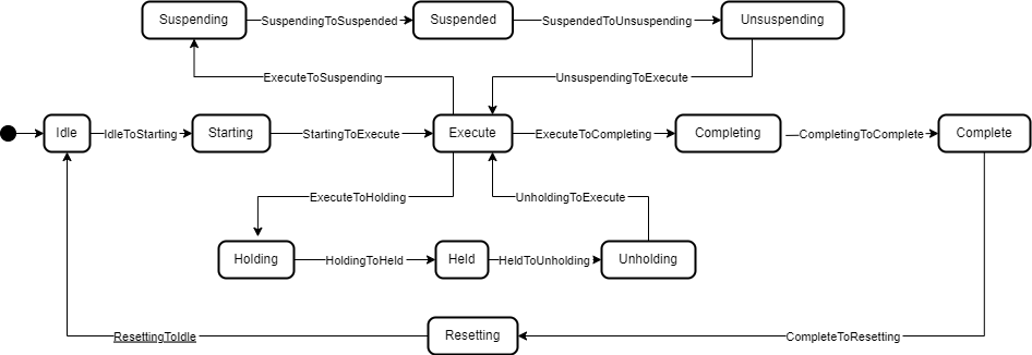
The RunningStateMachineType is a sub-state machine of the FunctionalStateMachine and includes detailed substates. It is formally defined in Table 32.
The Running StateMachine is depicted in Figure 17.
| Attribute | Value | ||||
| BrowseName | RunningStateMachineType | ||||
| IsAbstract | False | ||||
| References | Node Class | BrowseName | DataType | TypeDefinition | Other |
|---|---|---|---|---|---|
| Subtype of the FiniteStateMachineType defined in OPC 10000-5 | |||||
| 0:HasComponent | Object | Complete | StateType | ||
| 0:HasComponent | Object | CompleteToResetting | TransitionType | ||
| 0:HasComponent | Object | Completing | StateType | ||
| 0:HasComponent | Object | CompletingToComplete | TransitionType | ||
| 0:HasComponent | Object | Execute | StateType | ||
| 0:HasComponent | Object | ExecuteToCompleting | TransitionType | ||
| 0:HasComponent | Object | ExecuteToHolding | TransitionType | ||
| 0:HasComponent | Object | ExecuteToSuspending | TransitionType | ||
| 0:HasComponent | Object | Held | StateType | ||
| 0:HasComponent | Object | HeldToUnholding | TransitionType | ||
| 0:HasComponent | Method | Hold | O | ||
| 0:HasComponent | Object | Holding | StateType | ||
| 0:HasComponent | Object | HoldingToHeld | TransitionType | ||
| 0:HasComponent | Object | Idle | StateType | ||
| 0:HasComponent | Object | IdleToStarting | TransitionType | ||
| 0:HasComponent | Method | Reset | O | ||
| 0:HasComponent | Object | Resetting | StateType | ||
| 0:HasComponent | Object | ResettingToIdle | TransitionType | ||
| 0:HasComponent | Object | Starting | StateType | ||
| 0:HasComponent | Object | StartingToExecute | TransitionType | ||
| 0:HasComponent | Object | StartingToHolding | TransitionType | ||
| 0:HasComponent | Method | Suspend | O | ||
| 0:HasComponent | Object | Suspended | StateType | ||
| 0:HasComponent | Object | SuspendedToHolding | TransitionType | ||
| 0:HasComponent | Object | SuspendedToUnsuspending | TransitionType | ||
| 0:HasComponent | Object | Suspending | StateType | ||
| 0:HasComponent | Object | SuspendingToHolding | TransitionType | ||
| 0:HasComponent | Object | SuspendingToSuspended | TransitionType | ||
| 0:HasComponent | Method | ToComplete | O | ||
| 0:HasComponent | Method | Unhold | O | ||
| 0:HasComponent | Object | Unholding | StateType | ||
| 0:HasComponent | Object | UnholdingToExecute | TransitionType | ||
| 0:HasComponent | Object | UnholdingToHolding | TransitionType | ||
| 0:HasComponent | Method | Unsuspend | O | ||
| 0:HasComponent | Object | Unsuspending | StateType | ||
| 0:HasComponent | Object | UnsuspendingToExecute | TransitionType | ||
| 0:HasComponent | Object | UnsuspendingToHolding | TransitionType | ||
| Conformance Units | |||||
|---|---|---|---|---|---|
| LADS RunningStateMachineType | |||||
Complete: Complete indicates that the process associated with the active protocol has come to its defined end. The unit/device will wait in this state until a Reset command is issued (in which case it will transition to Resetting), or until the unit/device is Stopped or Aborted.
Completing: Once the process associated with the current mode has reached a defined threshold (e.g., the required number of samples for the current job have been analysed or the cultivation/fermentation process has reached is final stage in terms of cell count, product yield, cell viability, etc.), the unit/device transitions from Execute to Completing. All steps necessary to shut down the current process are carried out in this state. The unit/device then transitions automatically to the Complete state.
Execute: The unit/device is actively carrying out the behaviour or activity defined by the selected protocol and its associated processing mode. Examples of a unit/device in processing mode include when the unit/device is performing an analytical run, cultivation/fermentation in the case of a bioreactor, or another defined unit of operation provided by the instrument (e.g., separation in the case of a centrifuge).
Held: The unit/device is paused, waiting for internal process conditions to clear. In this state, the unit/device shall not continue processing, although it may dry cycle if required (e.g., maintaining process conditions critical for the preservation of the samples or culture). A transition to Unholding will occur once internal unit/device conditions have cleared, or if the Unhold command is initiated by an operator.
Holding: The unit/device will transition from Execute to Holding if conditions internal to the unit/device require a pause in processing. Examples of such conditions include low levels of materials required for processing (e.g., consumables, reagents, buffers, etc.) or other minor issues requiring operator service. After all steps required to hold the unit/device have been completed, the unit/device will transition automatically to the Held state.
Idle: The unit/device is in an error-free state, waiting to start. The unit/device transitions automatically to Idle after all steps necessary for Resetting have been completed. All conditions achieved during Resetting are maintained. A Start command will transition the unit/device from Idle to Starting.
Resetting: In response to a Reset command, the unit/device will transition to Resetting from either Stopped or Complete. In this state the unit/device attempts to clear any standing errors or stop causes. If successful, the unit/device transitions to Idle. No hazardous motion should occur while in this state.
Starting: The unit/device completes all steps necessary to begin execution of the active protocol. Typical steps during this state include but are not limited to inspecting system setup (checking sufficient supplies of resources and consumables), priming of fluids, homing of handling systems, or equilibration of process conditions. A Start command will cause the unit/device to transition from Idle to Starting. The unit/device will transition automatically from Starting to Execute once all required steps have been completed.
Suspended: The unit/device is paused, waiting for external process conditions to clear. In this state, the unit/device shall not continue processing, but may dry cycle if required (e.g., maintaining process conditions critical for the preservation of the samples or culture, including but not limited to temperature, oxygen or pH levels, etc.). Once external conditions have returned to normal, the unit/device will transition to Unsuspending, with or without operator intervention.
Suspending: The unit/device will transition from Execute to Suspending if conditions external to the unit/device require a pause in processing. Such conditions include faults to upstream or downstream equipment. The decision to Suspend may be made by a human operator supervising the process, an automated supervisory system monitoring the conditions of the overall process line/workflow, or by unit/device Sensors detecting downstream blockages or upstream scarcity of samples, etc. (In the former case, the unit/device is 'blocked"; in the latter case, the unit/device is "starved".) After all steps required to suspend the unit/device have been completed, the unit/device will automatically transition to the Suspended state.
Unholding: After all internal process conditions that caused the unit/device to hold have cleared, the unit/device completes all steps required to resume execution of the active protocol. Once all required actions to unhold the unit/device have been completed, the unit/device will transition automatically to the Execute state.
Unsuspending: After all external process conditions that caused the unit/device to suspend have cleared, the unit/device completes all steps required to resume execution of the active protocol.
The children of the RunningStateMachineType have additional References, which are defined in Table 33.
| SourceBrowsePath | Reference Type | Is Forward | TargetBrowsePath |
| IdleToStarting | 0:FromState | True | Idle |
| 0:ToState | True | Starting | |
| 0:HasEffect | True | TransitionEventType | |
| StartingToExecute | 0:FromState | True | Starting |
| 0:ToState | True | Execute | |
| 0:HasEffect | True | TransitionEventType | |
| ExecuteToCompleting | 0:FromState | True | Execute |
| 0:ToState | True | Completing | |
| 0:HasCause | True | ToComplete | |
| 0:HasEffect | True | TransitionEventType | |
| CompletingToComplete | 0:FromState | True | Completing |
| 0:ToState | True | Complete | |
| 0:HasEffect | True | TransitionEventType | |
| CompleteToResetting | 0:FromState | True | Complete |
| 0:ToState | True | Resetting | |
| 0:HasCause | True | Reset | |
| 0:HasEffect | True | TransitionEventType | |
| ResettingToIdle | 0:FromState | True | Resetting |
| 0:ToState | True | Idle | |
| 0:HasEffect | True | TransitionEventType | |
| ExecuteToSuspending | 0:FromState | True | Execute |
| 0:ToState | True | Suspending | |
| 0:HasCause | True | Suspend | |
| 0:HasEffect | True | TransitionEventType | |
| SuspendingToSuspended | 0:FromState | True | Suspending |
| 0:ToState | True | Suspended | |
| 0:HasEffect | True | TransitionEventType | |
| UnsuspendingToExecute | 0:FromState | True | Unsuspending |
| 0:ToState | True | Execute | |
| 0:HasEffect | True | TransitionEventType | |
| ExecuteToHolding | 0:FromState | True | Execute |
| 0:ToState | True | Holding | |
| 0:HasCause | True | Hold | |
| 0:HasEffect | True | TransitionEventType | |
| HoldingToHeld | 0:FromState | True | Holding |
| 0:ToState | True | Held | |
| 0:HasEffect | True | TransitionEventType | |
| HeldToUnholding | 0:FromState | True | Held |
| 0:ToState | True | Unholding | |
| 0:HasCause | True | Unhold | |
| 0:HasEffect | True | TransitionEventType | |
| UnholdingToExecute | 0:FromState | True | Unholding |
| 0:ToState | True | Execute | |
| 0:HasEffect | True | TransitionEventType |
| SourceBrowsePath | Reference Type | Is Forward | TargetBrowsePath |
| SuspendingToHolding | 0:FromState | True | Suspending |
| 0:ToState | True | Holding | |
| 0:HasCause | True | Hold | |
| 0:HasEffect | True | TransitionEventType | |
| StartingToHolding | 0:FromState | True | Starting |
| 0:ToState | True | Holding | |
| 0:HasCause | True | Hold | |
| 0:HasEffect | True | TransitionEventType | |
| SuspendedToHolding | 0:FromState | True | Suspended |
| 0:ToState | True | Holding | |
| 0:HasCause | True | Hold | |
| 0:HasEffect | True | TransitionEventType | |
| UnsuspendingToHolding | 0:FromState | True | Unsuspending |
| 0:ToState | True | Holding | |
| 0:HasCause | True | Hold | |
| 0:HasEffect | True | TransitionEventType | |
| UnholdingToHolding | 0:FromState | True | Unholding |
| 0:ToState | True | Holding | |
| 0:HasCause | True | Hold | |
| 0:HasEffect | True | TransitionEventType |
The Component Variables of the RunningStateMachineType have additional Attributes, as defined in Table 34.
| BrowsePath | Value Attribute | ||
| 1 | ||
| 2 | ||
| 3 | ||
| 4 | ||
| 5 | ||
| 6 | ||
| 7 | ||
| 8 | ||
| 9 | ||
| 10 | ||
| 11 | ||
| 12 | ||
| 1 | ||
| 2 | ||
| 5 | ||
| 6 | ||
| 7 | ||
| 8 | ||
| 9 | ||
| 10 | ||
| 11 | ||
| 12 |
| BrowsePath | Value Attribute | ||
| 13 | ||
| 14 | ||
| 15 | ||
| 16 | ||
| 17 | ||
| 18 | ||
| 19 |
7.1.6.2 Hold
The Hold Method allows an OPC UA Client to change the state of this state machine to Holding. The signature of this Method is specified below. Table 35 specifies its representation in the AddressSpace.
Signature
Hold ()| Attribute | Value | ||||
| BrowseName | Hold | ||||
| References | Node Class | BrowseName | DataType | TypeDefinition | ModellingRule |
|---|---|---|---|---|---|
7.1.6.3 Reset
The Reset Method allows an OPC UA Client to change the state of this state machine to Resetting. The signature of this Method is specified below. Table 36 specifies its representation in the AddressSpace.
Signature
Reset ()| Attribute | Value | ||||
| BrowseName | Reset | ||||
| References | Node Class | BrowseName | DataType | TypeDefinition | ModellingRule |
|---|---|---|---|---|---|
7.1.6.4 Suspend
The Suspend Method allows an OPC UA Client to change the state of this state machine to the Suspending state. The signature of this Method is specified below. Table 37 specifies its representation in the AddressSpace.
Signature
Suspend ()| Attribute | Value | ||||
| BrowseName | Suspend | ||||
| References | Node Class | BrowseName | DataType | TypeDefinition | ModellingRule |
|---|
7.1.6.5 ToComplete
The ToComplete Method allows an OPC UA Client to change the state of this state machine to Completed. The signature of this Method is specified below. Table 38 specifies its representation in the AddressSpace.
Signature
ToComplete ()| Attribute | Value | ||||
| BrowseName | ToComplete | ||||
| References | Node Class | BrowseName | DataType | TypeDefinition | ModellingRule |
|---|---|---|---|---|---|
7.1.6.6 Unhold
The Unhold Method allows an OPC UA Client to change the state of this state machine to Unholding. The signature of this Method is specified below. Table 39 specifies its representation in the AddressSpace.
Signature
Unhold ()| Attribute | Value | ||||
| BrowseName | Unhold | ||||
| References | Node Class | BrowseName | DataType | TypeDefinition | ModellingRule |
|---|---|---|---|---|---|
7.1.6.7 Unsuspend
The Unsuspend Method allows an OPC UA Client to change the state of this state machine to Unsuspending. The signature of this Method is specified below. Table 40 specifies its representation in the AddressSpace.
Signature
Unsuspend ()| Attribute | Value | ||||
| BrowseName | Unsuspend | ||||
| References | Node Class | BrowseName | DataType | TypeDefinition | ModellingRule |
|---|---|---|---|---|---|
7.1.7 FunctionalUnitStateMachineType Definition
7.1.7.1 Overview
The FunctionalUnitStateMachineType represents the state of a FunctionalUnit in a LADS Device. It uses the same StateTypes and TransitionTypes as its parent but specifies the additional Start Method to trigger state changes.
The FunctionalUnitStateMachineType is formally defined in Table 41.
| Attribute | Value | ||||
| BrowseName | FunctionalUnitStateMachineType | ||||
| IsAbstract | False | ||||
| References | Node Class | BrowseName | DataType | TypeDefinition | Other |
|---|---|---|---|---|---|
| Subtype of the FunctionalStateMachineType defined in 7.1.5 | |||||
| 0:HasComponent | Method | Start | O | ||
| 0:HasComponent | Method | StartProgram | O | ||
| Conformance Units | |||||
|---|---|---|---|---|---|
| LADS FunctionalUnitStateMachineType | |||||
Start is used to start a FunctionalUnit with properties.
StartProgram is used to start a FunctionalUnit with a Program Template.
7.1.7.2 Start
The Start Method is used when a Client application wants to initiate/execute an/the operation of a FunctionalUnit. The Properties Argument can be used to provide an optional list of property values when initiating the operation. The listed items represent key-value pairs that conform to the OPC UA KeyValuePair core datatype. The qualified name provided via the key field must match the BrowseName of a Property member in the FunctionalUnit's SupportedPropertySet.
The signature of this Method is specified below. Table 42 and Table 43 specify the Arguments and AddressSpace representation, respectively.
The Start Method should not be called by a Client with anonymous authentication.
Signature
	Start (
[in] KeyValuePair[] Properties)| Argument | Description |
| Properties | A set of Properties that parameterize the execution of the Functional Unit. |
| Attribute | Value | ||||
| BrowseName | Start | ||||
| References | Node Class | BrowseName | DataType | TypeDefinition | ModellingRule |
|---|---|---|---|---|---|
| 0:HasProperty | Variable | 0:InputArguments | Argument[1] | 0:PropertyType | M |
7.1.7.3 StartProgram
The StartProgram Method is used when a Client application wants to start running a program based on a ProgramTemplate of a FunctionalUnit. The Properties Argument can be used to provide an optional list of property values when initiating a program run. The listed items represent key-value pairs that conform to the OPC UA KeyValuePair core datatype. The qualified name provided via the key field must match the BrowseName of a Property member in the FunctionalUnit's SupportedPropertySet.
In contrast to the Start Method, additional fixed properties must also be set.
The signature of this Method is specified below. Table 44 and Table 45 specify the Arguments and AddressSpace representation, respectively.
The Start Method should not be called by a Client with anonymous authentication.
Signature
	StartProgram (
		[in]	0:String	ProgramTemplateId
		[in]	KeyValueType[]	Properties
		[in]	0:String	SupervisoryJobId
		[in]	0:String	SupervisoryTaskId
		[in]	SampleInfoType[]	Samples
[out] 0:String DeviceProgramRunId)| Argument | Description |
| ProgramTemplateId | The unique identifier of the program template used for the program-run. The template must be a member of the ProgramTemplateSet. |
| Properties | A Key/Value set for parameterization of the function. |
| SupervisoryJobId | The SupervisoryJobId assigned to this program. |
| SupervisoryTaskId | The Id of the SupervisoryTask. |
| Samples | An array of the SampleInfoType that describes the samples processed in this program-run. |
| DeviceProgramRunId | The Id of the created program run. |
| Attribute | Value | ||||
| BrowseName | StartProgram | ||||
| References | Node Class | BrowseName | DataType | TypeDefinition | ModellingRule |
|---|---|---|---|---|---|
| 0:HasProperty | Variable | 0:InputArguments | Argument[5] | 0:PropertyType | M |
| 0:HasProperty | Variable | 0:OutputArguments | Argument[1] | 0:PropertyType | M |
DeviceProgramRunId is the internal program identifier assigned by the Device to the program run to generate this result. It is used to identify a Result object and is returned to the Client when the StartProgram Method is called.
SupervisoryJobId is the identifier for the execution of a specific workflow, consisting of one or multiple tasks. It is provided as an Argument of the StartProgram() Method which initiates the program run.
SupervisoryTaskId is the unique identifier of the specific task in the supervisory system to which the result belongs. It is provided as an Argument of the StartProgram() Method which initiates the program run.
7.1.8 LADSComponentsType ObjectType Definition
The LADSComponentsType is used for organising LADSComponentsType objects in an unordered list structure. It is formally defined in Table 46.
| Attribute | Value | ||||
| BrowseName | LADSComponentsType | ||||
| IsAbstract | False | ||||
| References | Node Class | BrowseName | DataType | TypeDefinition | Other |
|---|---|---|---|---|---|
| Subtype of the MachineComponentsType defined in OPC 40001-1 | |||||
| 0:HasComponent | Object | <Component> | LADSComponentType | OP | |
| GeneratesEvent | ObjectType | GeneralModelChangeEventType | |||
| 0:HasProperty | Variable | NodeVersion | 0:String | 0:PropertyType | O |
| Conformance Units | |||||
|---|---|---|---|---|---|
| LADS LADSComponentsType | |||||
<Components> is a placeholder for the Components.
7.1.9 LADSOperationModeStateMachineType ObjectType Definition
The LADSOperationModeStateMachineType is a subtype of 4:MachineryOperationModeStateMachineType that adds optional Methods to the statemachine. It is formally defined in Table 46.
| Attribute | Value | ||||
| BrowseName | LADSOperationModeStateMachineType | ||||
| IsAbstract | False | ||||
| References | Node Class | BrowseName | DataType | TypeDefinition | Other |
|---|---|---|---|---|---|
| Subtype of the 4:MachineryOperationModeStateMachineType | |||||
| 0:HasComponent | Method | GotoMaintenance | O | ||
| 0:HasComponent | Method | GotoProcessing | O | ||
| 0:HasComponent | Method | GotoSetup | O | ||
| Conformance Units | |||||
|---|---|---|---|---|---|
| LADS LADSOperationModeStatemachineType | |||||
7.1.9.1 GotoMaintenance
The GotoMaintenance Method brings the LADSDevice in the Maintenance state.
The signature of this Method is specified below. Table 52 specifies its representation in the AddressSpace.
Signature
GotoMaintenance ()| Attribute | Value | ||||
| BrowseName | GotoMaintenance | ||||
| References | Node Class | BrowseName | DataType | TypeDefinition | ModellingRule |
|---|
7.1.9.2 GotoProcessing
The GotoMaintenance Method brings the LADSDevice in the Processing state.
The signature of this Method is specified below. Table 52 specifies its representation in the AddressSpace.
Signature
GotoProcessing ()| Attribute | Value | ||||
| BrowseName | GotoProcessing | ||||
| References | Node Class | BrowseName | DataType | TypeDefinition | ModellingRule |
|---|
7.1.9.3 GotoSetup
The GotoSetup Method brings the LADSDevice in the Setup state.
The signature of this Method is specified below. Table 52 specifies its representation in the AddressSpace.
Signature
GotoSetup ()| Attribute | Value | ||||
| BrowseName | GotoSetup | ||||
| References | Node Class | BrowseName | DataType | TypeDefinition | ModellingRule |
|---|
7.1.10 MaintenanceTaskType Definition
7.1.10.1 Overview
The MaintenanceTaskType shall be used to implement instances of maintenance tasks applicable at both the Device and Component levels. Maintenance tasks include activities such as periodic maintenance, cleaning, calibration, and validation.
Maintenance tasks for a Device shall be grouped under the Maintenance functional group present in the LADSDeviceType.
The MaintenanceTaskType is formally defined in Table 51.
| Attribute | Value | ||||
| BrowseName | MaintenanceTaskType | ||||
| IsAbstract | False | ||||
| References | Node Class | BrowseName | DataType | TypeDefinition | Other |
|---|---|---|---|---|---|
| Subtype of the MaintenanceRequiredAlarmType defined in OPC 10000-100 | |||||
| 0:HasProperty | Variable | LastExecutionDate | 0:UtcTime | 0:PropertyType | O |
| 0:HasProperty | Variable | LastOperatingCycles | 0:UInt32 | 0:PropertyType | O |
| 0:HasProperty | Variable | LastOperatingTime | 0:Duration | 0:PropertyType | O |
| 0:HasProperty | Variable | NextOperatingCycles | 0:UInt32 | 0:PropertyType | O |
| 0:HasProperty | Variable | NextOperatingTime | 0:Duration | 0:PropertyType | O |
| 0:HasProperty | Variable | RecurrencePeriod | 0:Duration | 0:PropertyType | O |
| 0:HasComponent | Method | ResetTask | O | ||
| 0:HasComponent | Method | StartTask | O | ||
| 0:HasComponent | Method | StopTask | O | ||
| 0:HasInterface | ObjectType | IMaintenanceEventType | Defined in OPC 10000-110 Section 12.2 | ||
| Applied from IMaintenanceEventType | |||||
| 0:HasProperty | Variable | 3:ConfigurationChanged | 0:Boolean | 0:PropertyType | O |
| 0:HasProperty | Variable | 3:EstimatedDowntime | 0:Duration | 0:PropertyType | O |
| 0:HasProperty | Variable | 3:MaintenanceMethod | 3:MaintenanceMethodEnum | 0:PropertyType | O |
| 0:HasComponent | Object | 3:MaintenanceState | 3:MaintenanceEventStateMachineType | M | |
| 0:HasProperty | Variable | 3:MaintenanceSupplier | 3:NameNodeIdDataType | 0:PropertyType | O |
| 0:HasProperty | Variable | 3:PartsOfAssetReplaced | 3:NameNodeIdDataType[] | 0:PropertyType | O |
| 0:HasProperty | Variable | 3:PartsOfAssetServiced | 3:NameNodeIdDataType[] | 0:PropertyType | O |
| 0:HasProperty | Variable | 3:PlannedDate | 0:UtcTime | 0:PropertyType | O |
| 0:HasProperty | Variable | 3:QualificationOfPersonnel | 3:NameNodeIdDataType | 0:PropertyType | O |
| Conformance Units | |||||
|---|---|---|---|---|---|
| LADS MaintenanceTaskType | |||||
LastExecutionDate is the date when the Task was last performed. Optional, as the Task may have never run before.
LastOperatingCycles is the number of cycles during the operating time (as defined in Section 9.3 of EN 13306-2017) recorded at the time of the last execution of the Task.
LastOperatingTime is the total amount of operating time (as defined in Section 9.3 of EN 13306-2017) in milliseconds (ms) by the Device at the time of the last execution of the Task.
NextOperatingCycles is the number of cycles during operating time (as defined in Section 9.3 of EN 13306-2017) to be completed before the next execution of the Task.
NextOperatingTime is the total amount of operating time (as defined in Section 9.3 of EN 13306-2017) in milliseconds (ms) by the Device before the next execution of the Task.
RecurrencePeriod is the period of repetition of the Task, specified in milliseconds. Optional, as not all Tasks have a recurrence period.
ResetTask Method resets the condition of the Task so that it is ready to be re-run.
Start Method starts the execution of the Task.
Stop Method stops the execution of the Task.
7.1.10.2 ResetTask
The ResetTask Method resets the execution of the Task so that it is ready to be re-run.
Optional, as instruments may not support resetting a maintenance task via a method call. The same effect can be achieved by means of a device-specific control.
Upon successful execution of the ResetTask Method, the MaintenanceState shall be changed to Planned and an accompanying event shall be raised. Also, the ActiveState and AckState properties are set to "False".
The signature of this Method is specified below. Table 52 specifies its representation in the AddressSpace.
Signature
ResetTask ()| Attribute | Value | ||||
| BrowseName | Reset | ||||
| References | Node Class | BrowseName | DataType | TypeDefinition | ModellingRule |
|---|
7.1.10.3 StartTask
The Start Method starts the execution of the Task.
Optional, as instruments may not support starting a maintenance task via a method call. The same effect can be achieved by means of a device-specific control.
Upon successful execution of the Start Method, the MaintenanceState shall be changed to Executing and an accompanying event shall be raised.
The signature of this Method is specified below. Table 53 specifies its representation in the AddressSpace.
Signature
StartTask ()| Attribute | Value | ||||
| BrowseName | StartTask | ||||
| References | Node Class | BrowseName | DataType | TypeDefinition | ModellingRule |
|---|
7.1.10.4 StopTask
The StopTask Method stops of the execution of the task.
Optional, as instruments may not support aborting the task via a method call. The same effect can be achieved by means of a device-specific control.
It includes 2 optional input parameters: MaintenanceTaskStopResult and Comment to document the outcome of the maintenance task.
Upon successful execution of the Stop Method, the MaintenanceState shall be changed to Finished and an accompanying event shall be raised. Also, the ActiveState and AckState properties are set to "False".
The signature of this Method is specified below. Table 54 and Table 55 specify the Arguments and AddressSpace representation, respectively.
Signature
	StopTask (
		[in]	MaintenanceTaskResultEnum	MaintenanceTaskStopResult,
[in] LocalizedText Comment)| Argument | Description |
| MaintenanceTaskStopResult | Give the reason why the task is stopped. |
| Comment | Add an additional comment to describe the call |
| Attribute | Value | ||||
| BrowseName | StopTask | ||||
| References | Node Class | BrowseName | DataType | TypeDefinition | ModellingRule |
|---|---|---|---|---|---|
| 0:HasProperty | Variable | 0:InputArguments | 0:Argument[] | 0:PropertyType | 0:Mandatory |