
7 OPC UA ObjectTypes
7.1 CraneMotionDeviceSystemType ObjectType Definition
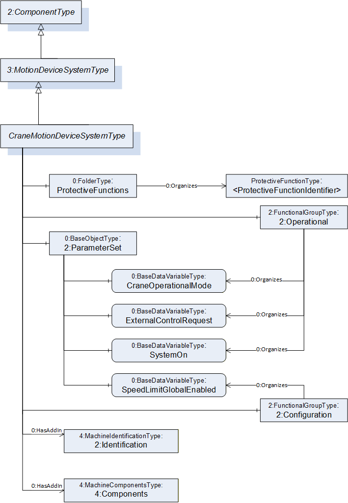
The CraneMotionDeviceSystemType provides a representation of a crane motion device system as an entry point to the OPC UA device set. At least one instance of a CraneMotionDeviceSystemType must be instantiated in the DeviceSet. This instance organises the information model of a complete crane system using instances of the described ObjectTypes.
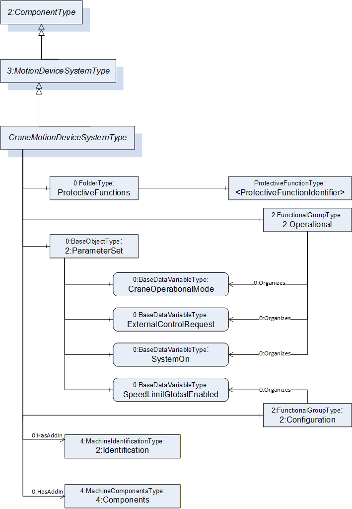
The CraneMotionDeviceSystemType represents the entire crane and contains its various components. The type is a subtype of the OPC 40010-1 MotionDeviceSystemType (OPC Robotics) and this is intended to provide compatibility with OPC 40010-1 aware clients. The CraneMotionDeviceSystemType is formally defined in Table 12.
| Attribute | Value | ||||
| BrowseName | CraneMotionDeviceSystemType | ||||
| IsAbstract | False | ||||
| References | Node Class | BrowseName | DataType | TypeDefinition | Other |
|---|---|---|---|---|---|
| Subtype of the 3:MotionDeviceSystemType defined in OPC 40010-1, i.e. inheriting the InstanceDeclarations of that Node. | |||||
| 0:HasComponent | Object | 2:ParameterSet | 0:BaseObjectType | M | |
| 0:HasComponent | Object | ProtectiveFunctions | 0:FolderType | O | |
| 0:HasAddIn | Object | 2:Identification | 4:MachineIdentificationType | M | |
| 0:HasAddIn | Object | 4:Components | 4:MachineComponentsType | O | |
| 0:HasComponent | Object | 2:Operational | 2:FunctionalGroupType | O | |
| 0:HasComponent | Object | 2:Configuration | 2:FunctionalGroupType | O | |
| Conformance Units | |||||
|---|---|---|---|---|---|
| Cranes Base Info CraneMotionDeviceSystemType |
ParameterSet contains all the variables of the CraneMotionDeviceSystemType. variables are also referenced by an Organizes from either Configuration or Operational FunctionalGroup.
ProtectiveFunctions is a Folder for both hardware and software functions designed to affect motion of the crane in order to protect personnel, equipment and/or the environment. Examples include force limiters (overload protection), limit switches and software anti-collision systems. A protective function can slow down and/or stop the motion of the crane in one or more axis.
The Identification Object provides identification information of the crane. It is specified in OPC 10000-100 and OPC 40001-1.
As defined in OPC 40001-1 4:Components allows the listing of all subcomponents of a CraneMotionDeviceSystem.
The Operational FunctionalGroup contains variables which represent the current state of the crane (motion device system). This is read-only, online data.
The Configuration FunctionalGroup contains variables which can be used to assess and/or affect the control of the crane, such as setting a speed limit for crane motions.
The components of the CraneMotionDeviceSystemType have additional subcomponents which are defined in Table 13.
| BrowsePath | References | NodeClass | BrowseName | DataType | TypeDefinition | Others |
| 2:ParameterSet | 0:HasComponent | Variable | CraneOperationalMode | CraneOperationalModeEnum | 0:BaseDataVariableType | M, RO |
| 2:ParameterSet | 0:HasComponent | Variable | ExternalControlRequest | ExternalControlRequestEnum | 0:BaseDataVariableType | O, RO |
| 2:ParameterSet | 0:HasComponent | Variable | SpeedLimitGlobalEnabled | 0:Boolean | 0:BaseDataVariableType | O, RW |
| 2:ParameterSet | 0:HasComponent | Variable | SystemOn | 0:Boolean | 0:BaseDataVariableType | M, RO |
| 2:Operational | 0:Organizes | Variable | CraneOperationalMode | CraneOperationalModeEnum | 0:BaseDataVariableType | M, RO |
| 2:Operational | 0:Organizes | Variable | ExternalControlRequest | ExternalControlRequestEnum | 0:BaseDataVariableType | O, RO |
| 2:Operational | 0:Organizes | Variable | SystemOn | 0:Boolean | 0:BaseDataVariableType | M, RO |
| 2:Configuration | 0:Organizes | Variable | SpeedLimitGlobalEnabled | 0:Boolean | 0:BaseDataVariableType | O, RW |
| ProtectiveFunctions | 0:HasComponent | Object | <ProtectiveFunctionIdentifier> | ProtectiveFunctionType | MP |
The parameter CraneOperationalMode provides information to the client about the mode of operation the crane is in. See Table 25 for the possible values for the mode enumerations and their descriptions.
The parameter ExternalControlRequestEnum provides information to the client about whether an external control request is active on the crane and other information about external controls. See Table 27 for the possible values for the mode enumeration and their descriptions.
The parameter SpeedLimitGlobalEnabled provides information to the client whether a global speed limit has been requested by a client. TRUE if a limitation has been requested, otherwise FALSE.
The parameter SystemOn provides information to the client whether the main power supply and all subject systems are able to operate the crane in less than an approximate value of 10 seconds requiring no more than one operator action. TRUE if able to operate in less than 10 seconds, otherwise FALSE. This timing can be higher in some special applications.
The parameter SpeedLimitGlobalEnable is a read/write variable used to enable and/or disable any and all speed limitations for this specific CraneMotionDeviceSystemType. TRUE if speed limitations are to be obeyed, otherwise FALSE.
The ProtectiveFunctions folder contain information about crane functions which are designed to protect personnel, equipment, the environment and/or the crane itself, described in detail by ProtectiveFunctionType. The use case is similar to OPC 40010-1 ProtectiveStopFunctionType and EmergencyStopFunctionType (OPC Robotics), but with the additional capability to also represent functions which slow down motions (instead of stopping) or stop motions in one direction while still allowing it in the other direction.
Note: If possible each of the values given in 2:ParameterSet should be instantiated and referenced again from their respective FunctionalGroup (Operational or Configuration).
7.2 CraneMotionDeviceType ObjectType Definition
7.2.1 Overview
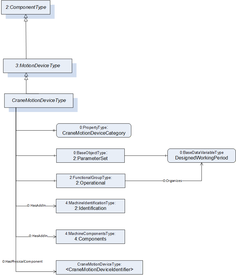
The CraneMotionDeviceType represents a physical moving component of the crane, such as a hoisting machinery or trolley. Load lifting attachments of the crane can also be represented as CraneMotionDeviceType objects.
The type is a subtype of the OPC 40010-1 MotionDeviceType and this is intended to provide compatibility with OPC 40010-1 aware clients. CraneMotionDeviceType is formally defined in Table 14.
| Attribute | Value | ||||
| BrowseName | CraneMotionDeviceType | ||||
| IsAbstract | False | ||||
| References | Node Class | BrowseName | DataType | TypeDefinition | Other |
|---|---|---|---|---|---|
| Subtype of the 3:MotionDeviceType defined in OPC 40010-1, i.e. inheriting the InstanceDeclarations of that Node. | |||||
| 0:HasAddIn | Object | 2:Identification | 4:MachineIdentificationType | M | |
| 0:HasAddIn | Object | 4:Components | 4:MachineComponentsType | O | |
| 0:HasComponent | Object | 2:Operational | 2:FunctionalGroupType | O | |
| 0:HasProperty | Variable | CraneMotionDeviceCategory | CraneMotionDeviceCategoryEnum | 0:PropertyType | M, RO |
| 0:HasPhysicalComponent | Object | <CraneMotionDeviceIdentifier> | CraneMotionDeviceType | OP | |
| Conformance Units | |||||
|---|---|---|---|---|---|
| Cranes Base Info CraneMotionDeviceType |
The Operational FunctionalGroup contains variables which represent the current state of the crane component (motion device). This is read-only, online data.
ParameterSet contains all the variables of the CraneMotionDeviceSystemType. Variables are also referenced by an Organizes from the Operational FunctionalGroup.
The Identification Object provides identification information of the crane component. It is specified in OPC 10000-100 and OPC 40001-1.
As defined in OPC 40001-1 4:Components allows the listing of all subcomponents of a CraneMotionDevice.
Note: If possible each of the values given in 2:ParameterSet should be instantiated and referenced again from the Operational FunctionalGroup.
CraneMotionDeviceCategory property describes which category this motion device belongs to in the domain of material handling. The enumeration contains different categories including hoists, trolley traversing machineries, bridge or gantry travelling machineries, load lifting attachments etc.
The <CraneMotionDeviceIdentifier> Object with its Hierarchical Reference HasPhysicalComponent shall be used to reflect the physical relationship between CraneMotionDeviceTypes. The Forward Direction of this reference represents the relationship component to subcomponent. Only direct subcomponents shall be referenced via HasPhysicalComponent Reference
The components of the CraneMotionDeviceType have additional subcomponents which are defined in Table 15.
| BrowsePath | References | NodeClass | BrowseName | DataType | TypeDefinition | Others |
| 2:ParameterSet | 0:HasComponent | Variable | DesignedWorkingPeriod | 0:Double | 0:AnalogUnitType | O, RO |
| 2:Operational | 0:Organizes | Variable | DesignedWorkingPeriod | 0:Double | 0:AnalogUnitType | O, RO |
The DesignedWorkingPeriod variable contains the lowest ISO 12482 designed working period (DWP) value of this component, if available. It is a percentage, initial value: 100.0%.
7.3 CraneAxisType ObjectType Definition
7.3.1 Overview
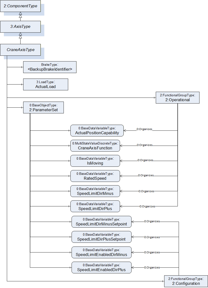
The CraneAxisType represents the crane axis and contains its various components. The type is a subtype of the OPC 40010-1 AxisType (OPC Robotics) and this is intended to provide compatibility with OPC 40010-1 aware clients. The CraneAxisType is formally defined in Table 16.
| Attribute | Value | ||||
| BrowseName | CraneAxisType | ||||
| IsAbstract | False | ||||
| References | Node Class | BrowseName | DataType | TypeDefinition | Other |
|---|---|---|---|---|---|
| Subtype of the 3:AxisType defined in OPC 40010-1, i. e. inheriting the InstanceDeclarations of that Node. | |||||
| 0:HasComponent | Object | ActualLoad | 3:LoadType | O | |
| 0:HasComponent | Object | <BackupBrakeIdentifier> | BrakeType | OP | |
| 0:HasComponent | Object | 2:Configuration | 2:FunctionalGroupType | O | |
| 0:HasComponent | Object | 2:Operational | 2:FunctionalGroupType | O | |
| Conformance Units | |||||
|---|---|---|---|---|---|
| Cranes Base Info CraneAxisType |
The ActualLoad object represents the load lifted by the crane. This object is mostly used in hoisting axis. The type (LoadType) is the one defined by OPC 40010-1 (OPC Robotics) and is used to represent the mass of the load, and optionally also inertia and/or the center of mass.
The <BackupBrakeIdentifier> object indicates that the axis may contain one or more backup brakes represented by BrakeType instances.
The Operational FunctionalGroup contains variables which represent the current state of the axis. These are read-only variables.
The Configuration FunctionalGroup contains variables which can be used to assess and/or affect the control of the axis, such as setting speed limits.
The components of the CraneAxisType have additional subcomponents which are defined in Table 17.
| BrowsePath | References | NodeClass | BrowseName | DataType | TypeDefinition | Others |
| 2:ParameterSet | 0:HasComponent | Variable | ActualPositionCapability | 0:Boolean | 0:BaseDataVariableType | M, RO |
| 2:ParameterSet | 0:HasComponent | Variable | CraneAxisFunction | 0:UInt16[] | 0:MultiStateValueDiscreteType | O, RO |
| 2:ParameterSet | 0:HasComponent | Variable | IsMoving | 0:Boolean | 0:BaseDataVariableType | O, RO |
| 2:ParameterSet | 0:HasComponent | Variable | RatedSpeed | 0:Double | 0:AnalogUnitType | O, RO |
| 2:ParameterSet | 0:HasComponent | Variable | SpeedLimitDirMinus | 0:Double | 0:AnalogUnitType | O, RO |
| 2:ParameterSet | 0:HasComponent | Variable | SpeedLimitDirMinusSetpoint | 0:Double | 0:AnalogUnitType | O, RW |
| 2:ParameterSet | 0:HasComponent | Variable | SpeedLimitDirPlus | 0:Double | 0:AnalogUnitType | O, RO |
| 2:ParameterSet | 0:HasComponent | Variable | SpeedLimitDirPlusSetpoint | 0:Double | 0:AnalogUnitType | O, RW |
| 2:ParameterSet | 0:HasComponent | Variable | SpeedLimitEnabledDirMinus | 0:Boolean | 0:BaseDataVariableType | O, RW |
| 2:ParameterSet | 0:HasComponent | Variable | SpeedLimitEnabledDirPlus | 0:Boolean | 0:BaseDataVariableType | O, RW |
| 2:Operational | 0:Organizes | Variable | ActualPositionCapability | 0:Boolean | 0:BaseDataVariableType | M, RO |
| 2:Operational | 0:Organizes | Variable | CraneAxisFunction | 0:UInt16[] | 0:MultiStateValueDiscreteType | O, RO |
| 2:Operational | 0:Organizes | Variable | IsMoving | 0:Boolean | 0:BaseDataVariableType | O, RO |
| 2:Operational | 0:Organizes | Variable | RatedSpeed | 0:Double | 0:AnalogUnitType | O, RO |
| 2:Operational | 0:Organizes | Variable | SpeedLimitDirMinus | 0:Double | 0:AnalogUnitType | O, RO |
| 2:Operational | 0:Organizes | Variable | SpeedLimitDirPlus | 0:Double | 0:AnalogUnitType | O, RO |
| 2:Configuration | 0:Organizes | Variable | SpeedLimitDirMinusSetpoint | 0:Double | 0:AnalogUnitType | O, RW |
| 2:Configuration | 0:Organizes | Variable | SpeedLimitDirPlusSetpoint | 0:Double | 0:AnalogUnitType | O, RW |
| 2:Configuration | 0:Organizes | Variable | SpeedLimitEnabledDirMinus | 0:Boolean | 0:BaseDataVariableType | O, RW |
| 2:Configuration | 0:Organizes | Variable | SpeedLimitEnabledDirPlus | 0:Boolean | 0:BaseDataVariableType | O, RW |
The ActualPositionCapability describes if the crane is able to give the position of the axis. The crane must be equipped with the necessary devices to provide this type of information. If the variable value is True, the axis position can be obtained from the variable ActualPosition inherited from the OPC 40010-1 (OPC Robotics).
The CraneAxisFunction describes the axis operating mode. The possible values are described in Table 18.
The IsMoving indicates if the axis is moving (TRUE) or not (FALSE).
The RatedSpeed indicates the rated (nominal) speed of the axis.
The SpeedLimitDirMinus indicates the speed limitation value active on the control system, in direction where position value decreases, in percentage of rated speed, range [0%..100%].
The SpeedLimitDirMinusSetpoint indicates the speed limitation request written from client, in direction where position value decreases, in percentage of rated speed, range [0%..100%].
The SpeedLimitEnabledDirMinus indicates a speed limitation request active, written from client, in direction where position value decreases. True if a client requests the speed to be limited in this direction, false if speed doesn't need to be limited.
The SpeedLimitDirPlus indicates the speed limitation value active on the control system, in direction where position value increases, in percentage of rated speed, range [0%..100%].
The SpeedLimitDirPlusSetpoint indicates the speed limitation request written from client, in direction where position value increases, in percentage of rated speed, range [0%..100%].
The SpeedLimitEnabledDirPlus indicates a speed limitation request active, written from client, in direction where position value increases. True if a client requests the speed to be limited in this direction, false if speed doesn't need to be limited.
7.3.2 Variable CraneAxisFunction
To be extendable for vendor specific extensions later, the TypeDefinition is MultiStateValueDiscreteType with its mandatory Properties EnumValues and ValueAsText must be filled with the supported values which are defined in Table 18. The EnumValues Property is an array of EnumValueType. Each entry of the array represents one enumeration value with its integer notation, a human-readable representation (DisplayName), and a description. Each instance shall have the values 0 to 8, which are defined in Table 18. Element numbers 9-15 are reserved for future use. If vendors add specific elements, the range 9-15 shall be filled with ‘null’-strings. The variable CraneAxisFunction exposes the current integer notation in their Value Attribute. The ValueAsText Property shall provide the localized text representation of the current enumeration value (Value Attribute of Variable CraneAxisFunction).
| DisplayName | Value | Description |
| RATED_SPEED | 0 | The axis moves at rated speed. |
| EXTENDED_SPEED | 1 | The axis moves above the rated speed when load is under certain percentage of rated load. This function reduces the load cycle time and can be used for hoisting. |
| MICROSPEED | 2 | Microspeed turns large joystick movements on the operator interface into slow and exact load movements. This function assists in very accurate and precise load handling and reduces the risk of collision and can be used for hoisting and travelling. |
| INCHING | 3 | Inching is designed to ensure accurate final load positioning by allowing the crane operator to move the load in small increments. This function assists in very accurate and precise load handling and reduces the risk of collision and can be used for hoisting and travelling. |
| ANTISWAY | 4 | This function limits load swing by controlling the bridge and trolley acceleration and deceleration. Antisway allows faster load handling and more precise positioning. This feature also reduces the risk of damage to the load, crane and surrounding area. |
| TANDEM_HOIST | 5 | Two or more hoists are operated from a single control station for handling of a single load. Two or more load lifting attachments’/hooks’ positions are synchronized. This function gives more accuracy when two or more hoists are used at the same time. Hoisting speeds are the same within the tolerances required for the particular application. |
| TANDEM_TROLLEY | 6 | Two or more trolleys are operated from a single control station for handling of a single load. Horizontal speeds are the same within the tolerances required for the particular application. |
| TANDEM_CRANE | 7 | This function allows the operator to control two cranes at the same time from one control station. The operator controls two cranes as one. This feature is useful when the operator needs to handle a single load with two cranes. |
| PRESET_DESTINATION | 8 | This function allows the operator to move the crane to a predefined position without effort. With a single operator input, the crane carries out the sequence to reach the selected destination. |
| null | 9 - 15 | null |
| Vendor specific | ≥ 16 | Vendor specific description |
7.4 BrakeType ObjectType Definition
The BrakeType is used to describe the status of a brake. In this specification, it is only defined to model the backup brakes. A service brake status is provided by the BrakeReleased variable of the OPC 40010-1 (OPC Robotics) MotorType object. The Figure 13 shows an overview of this type.
The BrakeType represents the backup brake and contains its various components. The BrakeType is formally defined in Table 19.
| Attribute | Value | ||||
| BrowseName | BrakeType | ||||
| IsAbstract | False | ||||
| References | Node Class | BrowseName | DataType | TypeDefinition | Other |
|---|---|---|---|---|---|
| Subtype of the 2:ComponentType defined in OPC 10000-100, i. e. inheriting the InstanceDeclarations of that Node. | |||||
| 0:HasComponent | Object | 2:Operational | 2:FunctionalGroupType | O | |
| 0:HasComponent | Object | 2:ParameterSet | 0:BaseObjectType | M | |
| 0:HasAddIn | Object | 2:Identification | 4:MachineryComponentIdentificationType | O | |
| Conformance Units | |||||
|---|---|---|---|---|---|
| Cranes Base Info BrakeType |
The Identification Object provides identification information of the brake. It is specified in OPC 10000-100 and OPC 40001-1.
ParameterSet contains all the variables of the BrakeType. Variables are also referenced by an Organizes from Operational FunctionalGroup.
The components of the BrakeType have additional subcomponents which are defined in Table 20.
| BrowsePath | References | NodeClass | BrowseName | DataType | TypeDefinition | Others |
| 2:ParameterSet | 0:HasComponent | Variable | BrakeReleased | 0:Boolean | 0:BaseDataVariableType | M, RO |
| 2:Operational | 0:Organizes | Variable | BrakeReleased | 0:Boolean | 0:BaseDataVariableType | M, RO |
The BrakeReleased variable describes the current state of the brake. It is TRUE when the brake is not engaged and FALSE when the brake is stopping the motion.
7.5 CraneMotorType ObjectType Definition
The CraneMotorType describes a motor in a power train. The Figure 14 shows an overview of this type.
The CraneMotorType represents a motor in a power train and contains its various components. The type is a subtype of the OPC 40010-1 MotorType (OPC Robotics) and this is intended to provide compatibility with OPC 40010-1 aware clients. The CraneMotorType is formally defined in Table 21.
| Attribute | Value | ||||
| BrowseName | CraneMotorType | ||||
| IsAbstract | False | ||||
| References | Node Class | BrowseName | DataType | TypeDefinition | Other |
|---|---|---|---|---|---|
| Subtype of the 3:MotorType defined in OPC 10000-100, i. e. inheriting the InstanceDeclarations of that Node. | |||||
| 0:HasAddIn | Object | 2:Identification | 4:MachineryComponentIdentificationType | O | |
| 0:HasComponent | Object | 2:Operational | 2:FunctionalGroupType | O | |
| Conformance Units | |||||
|---|---|---|---|---|---|
| Cranes Base Info CraneMotorType |
The Identification Object provides identification information of the motor. It is specified in OPC 10000-100 and OPC 40001-1.
The Operational FunctionalGroup contains variables which represent the current state of the motor. This is read-only.
The components of the CraneMotorType have additional subcomponents which are defined in Table 22.
| BrowsePath | References | NodeClass | BrowseName | DataType | TypeDefinition | Others |
| 2:ParameterSet | 0:HasComponent | Variable | Overheated | 0:Boolean | 0:BaseDataVariableType | O, RO |
| 2:Operational | 0:Organizes | Variable | Overheated | 0:Boolean | 0:BaseDataVariableType | O, RO |
The Overheated variable describes if the motor exceeds the maximum operating temperature. Overheated is TRUE if the motor temperature is above the limit. FALSE otherwise.
7.6 ProtectiveFunctionType ObjectType Definition
7.6.1 Overview
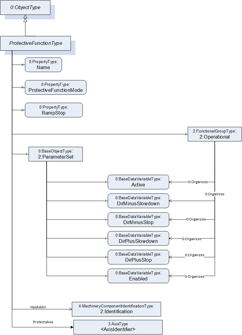
The ProtectiveFunctionType represents a hardware or software function designed to affect motion of the crane in order to protect personnel, equipment and/or the environment. Examples include force limiters (overload protection), limit switches and software anti-collision systems. A protective function can slow down and/or stop the motion of the crane in one or more axis. The use case is similar to OPC 40010-1 ProtectiveStopFunctionType and EmergencyStopFunctionType (OPC Robotics), but with the additional capability to also represent functions which slow down motions (instead of stopping) or stop motions in one direction while still allowing it in the other direction. ProtectiveFunctionType is formally defined in Table 23.
| Attribute | Value | ||||
| BrowseName | ProtectiveFunctionType | ||||
| IsAbstract | False | ||||
| References | Node Class | BrowseName | DataType | TypeDefinition | Other |
|---|---|---|---|---|---|
| Subtype of the 0:BaseObjectType defined in OPC 10000-100, i. e. inheriting the InstanceDeclarations of that Node. | |||||
| 0:HasAddIn | Object | 2:Identification | 4:MachineryComponentIdentificationType | O | |
| 0:HasComponent | Object | 2:ParameterSet | 0:BaseObjectType | M | |
| 0:HasComponent | Object | 2:Operational | 2:FunctionalGroupType | O | |
| 0:HasProperty | Variable | Name | 0:String | 0:PropertyType | O, RO |
| 0:HasProperty | Variable | ProtectiveFunctionMode | ProtectiveFunctionEnum | 0:PropertyType | O, RO |
| 0:HasProperty | Variable | RampDown | 0:Boolean | 0:PropertyType | O, RO |
| Conformance Units | |||||
|---|---|---|---|---|---|
| Cranes Base Info ProtectiveFunctionType |
The Name variable contains a human-readable textual identifier of the function.
The Identification Object provides identification information of the protective function. It is specified in OPC 10000-100 and OPC 40001-1.
The Operational FunctionalGroup contains variables which represent the current state of the protective function. This is read-only.
The ProtectiveFunctionMode variable describes what kind of protective function a specific instance of ProtectiveFunctionType describes, e. g. force limiter for overload protection devices or motion limiter for limit switches etc. The enumeration is defined in 8.4 ProtectiveFunctionEnum.
The components of the ProtectiveFunctionType have additional subcomponents which are defined in Table 17.
The RampDown Property indicates where a motion is slowed down using a graceful ramp down e.g. using software functionality instead of brakes.
An instance of the ProtectiveFunctionType can have multiple associated axis, instances of the 3:AxisType, which are protected by the protective function. The Non-Hierarchical Reference ProtectsAxis is used to express this relation. For more information on this reference, see section 9.1.
| BrowsePath | References | NodeClass | BrowseName | DataType | TypeDefinition | Others |
| 2:ParameterSet | 0:HasComponent | Variable | Active | 0:Boolean | 0:BaseDataVariableType | O, RO |
| 2:ParameterSet | 0:HasComponent | Variable | DirMinusSlowdown | 0:Boolean | 0:BaseDataVariableType | O, RO |
| 2:ParameterSet | 0:HasComponent | Variable | DirMinusStop | 0:Boolean | 0:BaseDataVariableType | O, RO |
| 2:ParameterSet | 0:HasComponent | Variable | DirPlusSlowdown | 0:Boolean | 0:BaseDataVariableType | O, RO |
| 2:ParameterSet | 0:HasComponent | Variable | DirPlusStop | 0:Boolean | 0:BaseDataVariableType | O, RO |
| 2:ParameterSet | 0:HasComponent | Variable | Enabled | 0:Boolean | 0:BaseDataVariableType | O, RO |
| 2:Operational | 0:Organizes | Variable | Active | 0:Boolean | 0:BaseDataVariableType | O, RO |
| 2:Operational | 0:Organizes | Variable | DirMinusSlowdown | 0:Boolean | 0:BaseDataVariableType | O, RO |
| 2:Operational | 0:Organizes | Variable | DirMinusStop | 0:Boolean | 0:BaseDataVariableType | O, RO |
| 2:Operational | 0:Organizes | Variable | DirPlusSlowdown | 0:Boolean | 0:BaseDataVariableType | O, RO |
| 2:Operational | 0:Organizes | Variable | DirPlusStop | 0:Boolean | 0:BaseDataVariableType | O, RO |
| 2:Operational | 0:Organizes | Variable | Enabled | 0:Boolean | 0:BaseDataVariableType | O, RO |
The Active variable provides information about the protective function state. It is TRUE if this particular protective function is active, i. e. that a stop or slowdown is initiated, FALSE otherwise. If Enabled is FALSE, then Active shall be FALSE.
The DirMinusSlowdown variable provides information about the speed reduction capabilities of the protective function. When TRUE, slowdown movement is enabled for direction where position value decreases (minus).
The DirMinusStop variable provides information about the stop capabilities of the protective function. When TRUE, Stop is enabled for direction where position value decreases (minus).
The DirPlusSlowdown variable provides information about the speed reduction capabilities of the protective function. When TRUE, slowdown movement is enabled for direction where position value increases (plus).
The DirPlusStop variable provides information about the stop capabilities of the protective function. When TRUE, stop is enabled for direction where position value increases (plus).
The Enabled variable provides information about the availability of the protective function. It is TRUE if this protective function is currently supervising the system, FALSE otherwise. A protective function may or may not be enabled at all times, e. g. the protective stop function of the safety doors are typically enabled in automatic operational mode and disabled in manual mode.