
7 OPC UA ObjectTypes
7.1 IOLinkDeviceType ObjectType Definition
7.1.1 Example
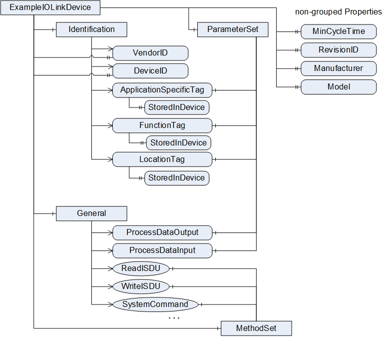
In Figure 11 an example of an instance of the IOLinkDeviceType is shown. This example is using only the mandatory InstanceDeclarations, and excluding several mandatory Methods, in order to give an overview on the ObjectType. Several Properties are directly connected to the Object, whereas the Parameters are connected via the ParameterSet, Methods via the MethodSet and both organized via different FunctionalGroups (Identification and General).
7.1.2 Overview
The IOLinkDeviceType provides the generic information of an IO-Link Device and is formally defined in Table 8.
| Attribute | Value | |||||
| BrowseName | IOLinkDeviceType | |||||
| IsAbstract | False | |||||
| References | Node Class | BrowseName | DataType | TypeDefinition | Modelling Rule | |
|---|---|---|---|---|---|---|
| Subtype of TopologyElementType defined in OPC 10000-100. | ||||||
| HasComponent | Object | 2:ParameterSet | BaseObjectType | Mandatory | ||
| HasComponent | Object | 2:MethodSet | BaseObjectType | Mandatory | ||
| HasComponent | Object | 2:Identification | FunctionalGroupType | Mandatory | ||
| HasComponent | Object | General | FunctionalGroupType | Mandatory | ||
| HasProperty | Variable | 2:SerialNumber | String | PropertyType | Optional | |
| HasProperty | Variable | 2:Manufacturer | LocalizedText | PropertyType | Mandatory | |
| HasProperty | Variable | 2:Model | LocalizedText | PropertyType | Mandatory | |
| HasProperty | Variable | 2:HardwareRevision | String | PropertyType | Optional | |
| HasProperty | Variable | 2:SoftwareRevision | String | PropertyType | Optional | |
| HasComponent | Variable | 2:DeviceHealth | DeviceHealthEnum | BaseDataVariableType | Optional | |
| HasProperty | Variable | MinCycleTime | Duration | PropertyType | Mandatory | |
| HasProperty | Variable | RevisionID | String | PropertyType | Mandatory | |
| HasProperty | Variable | VendorID | UInt16 | PropertyType | Mandatory | |
| HasProperty | Variable | DeviceID | UInt32 | PropertyType | Mandatory | |
| HasProperty | Variable | DeviceAccessLocks | UInt16 | PropertyType | Optional | |
| HasProperty | Variable | ProfileCharacteristic | UInt16[] | PropertyType | Optional | |
| HasProperty | Variable | VendorText | String | PropertyType | Optional | |
| HasProperty | Variable | ProductID | String | PropertyType | Optional | |
| HasProperty | Variable | ProductText | String | PropertyType | Optional | |
| HasComponent | Object | Alarms | FolderType | Optional | ||
| GeneratesEvent | ObjectType | IOLinkDeviceEventType | Defined in 9.3. | |||
| GeneratesEvent | ObjectType | IOLinkDeviceAlarmType | Defined in 9.8 | |||
The IOLinkDeviceType ObjectType is a concrete type and can be used directly, if the server does not have an IODD describing the device. If the server has such an IODD, a subtype shall be created representing the concrete IODD (see section 7.3 for details).
The ObjectType inherits the following InstanceDeclarations directly or indirectly from the TopologyElementType defined in OPC 10000-100.
The optional Object ParameterSet is used to reference all Parameters and shall be provided. Therefore, the ObjectType overrides the Object and changes the ModellingRule to Mandatory.
The optional Object MethodSet is used to reference all Methods and shall be provided. Therefore, the ObjectType overrides the Object and changes the ModellingRule to Mandatory.
The optional Object Identification shall be provided and shall reference the Parameters defined in Table 9. Those Parameters together uniquely identify the device (see OPC 10000-100 for details). Therefore, the ObjectType overrides the Object and changes the ModellingRule to Mandatory.
| References | BrowseName | Comment |
| Organizes | DeviceID | Variable defined in Table 8. |
| Organizes | VendorID | Variable defined in Table 8. |
| Organizes | 2:SerialNumber | Variable defined in Table 8. |
| Organizes | ApplicationSpecificTag | Variable defined in Table 12. |
| Organizes | FunctionTag | Variable defined in Table 12. |
| Organizes | LocationTag | Variable defined in Table 12. |
The Object <GroupIdentifier> has the ModellingRule OptionalPlaceholder and is intended to group the Parameters. It is already used in the ObjectType to define the General Object.
The optional Object Lock can be supported by a server to provide locking capabilities (see OPC 10000-100 for details). This is intended to prevent different clients and users to configure an IO-Link Device at the same time. The DeviceAccessLocks is used to disable the configuration of an IO-Link Device in general while it is set.
The ObjectType uses some InstanceDeclarations the same way as the DeviceType defined in OPC 10000-100.
The Variable SerialNumber of DataType String shall be mapped to ISDU Index 0x0015 (Serial Number). If the device does not support this ISDU Index, the Variable shall not be provided.
The Variable Manufacturer of DataType LocalizedText shall be mapped to ISDU Index 0x0010 (Vendor Name). As the name is intended to be locale-agnostic in IO-Link, the server may provide it with any LocaleId, the string shall be mapped to the text part of the LocalizedText. If the device does not support this ISDU Index, the VendorID (0x07 and 0x08 of Direct Parameter Page 1) shall be used, and either provided as integer representation in the text-part or by translating it internally to the Vendor Name managed by the IO-Link Community.
The Variable Model of DataType LocalizedText shall be mapped to ISDU Index 0x0012 (Product Name). As the name is intended to be locale-agnostic in IO-Link, the server may provide it with any LocaleId, the string shall be mapped to the text part of the LocalizedText. If the device does not support this ISDU Index, the DeviceID (0x09, 0x0A and 0x0B of Direct Parameter Page 1) shall be used, and provided as integer representation in the text-part.
The Variable HardwareRevision of DataType String shall be mapped to ISDU Index 0x0016 (Hardware Revision). If the device does not support this ISDU Index, the Variable shall not be provided.
The Variable SoftwareRevision of DataType String shall be mapped to ISDU Index 0x0017 (Firmware Revision). If the device does not support this ISDU Index, the Variable shall not be provided.
The Variable DeviceHealth of DataType DeviceHealthEnum shall be mapped to ISDU Index 0x0024 (Device Status). If the device does not support this ISDU Index, the Variable shall not be provided. The mapping of the concrete values is defined in Table 10.
| Device Status | DeviceHealth |
| 0 (Device is operating properly) | NORMAL_0 |
| 1 (Maintenance-Required) | MAINTENANCE_REQUIRED_4 |
| 2 (Out-of-Specification) | OFF_SPEC_3 |
| 3 (Functional-Check) | CHECK_FUNCTION_2 |
| 4 (Failure) | FAILURE_1 |
| 5 - 255 (Reserved) | - (would return a bad code) |
The ObjectType defines additional InstanceDeclarations:
The mandatory Object General shall reference the Parameters and Methods defined in Table 11. It provides Parameters and Methods that are generally available on IO-Link Devices based on the IO-Link Specification.
| References | BrowseName | Comment |
| Organizes | ApplicationSpecificTag | Variable defined in Table 12. |
| Organizes | FunctionTag | Variable defined in Table 12. |
| Organizes | LocationTag | Variable defined in Table 12. |
| Organizes | ErrorCount | Variable defined in Table 12. |
| Organizes | DetailedDeviceStatus | Variable defined in Table 12. |
| Organizes | ProcessDataOutput | Variable defined in Table 12. |
| Organizes | ProcessDataInput | Variable defined in Table 12. |
| Organizes | OffsetTime | Variable defined in Table 12. |
| Organizes | ReadISDU | Method defined in Table 16. |
| Organizes | WriteISDU | Method defined in Table 16. |
| Organizes | SystemCommand | Method defined in Table 16. |
| Organizes | ParamUploadFromDeviceStart | Method defined in Table 16. |
| Organizes | ParamUploadFromDeviceStop | Method defined in Table 16. |
| Organizes | ParamDownloadToDeviceStart | Method defined in Table 16. |
| Organizes | ParamDownloadToDeviceStop | Method defined in Table 16. |
| Organizes | ParamDownloadToDeviceStore | Method defined in Table 16. |
| Organizes | ParamBreak | Method defined in Table 16. |
| Organizes | DeviceReset | Method defined in Table 16. |
| Organizes | ApplicationReset | Method defined in Table 16. |
| Organizes | RestoreFactorySettings | Method defined in Table 16. |
The read-only Variable MinCycleTime shall be mapped to address 0x02 of Direct Parameter Page 1. The value shall be mapped to Duration (see 12.2.7.2 for details).
The read-only Variable RevisionID shall be mapped to address 0x04 of Direct Parameter Page 1. The value (one byte) shall be mapped to a String using the following rules: The MajorRev (Bit 4 to 7) shall be mapped to an Integer without leading zeros, the MinorRev (Bit 0 to 3) shall be mapped to an Integer without leading zeros and composed to a String as "<MajorRev>.<MinorRev>". For example, the RevisionID for IO-Link 1.1 shall become the String "1.1".
The read-only Variable VendorID shall be mapped to address 0x07 and 0x08 of Direct Parameter Page 1. The value (two bytes) shall be mapped to an UInt16, using Big Endian and 0x07 being the most significant byte (MSB).
The read-only Variable DeviceID shall be mapped to address 0x09, 0x0A and 0x0B of Direct Parameter Page 1. The value (three bytes) shall be mapped to an UInt32 (using the lowest three bytes), using Big Endian and 0x09 being the MSB.
The writable, optional Variable DeviceAccessLocks shall be mapped to ISDU Index 0x000C. The value (RecordT of BooleanT of length 16) shall be mapped to an UInt16, where the lowest bit represents the first Boolean of the record. The Variable gives information whether the parameterization of the device is locked in general, the local parameterization or the local user interface is locked (details see IO-Link Specification). By writing the Variable the locks can also be changed. If the device supports the ISDU Index, the server shall provide the Variable, otherwise it shall not provide the Variable.
The read-only Variable ProfileCharacteristic shall be mapped to ISDU Index 0x000D. The value (array of UIntegerT16) shall be mapped to an array of UInt16. If the device supports the ISDU Index, the server shall provide the Variable, otherwise it shall not provide the Variable.
The read-only Variable VendorText shall be mapped to ISDU Index 0x0011. The value (StringT) shall be mapped to a String. If the device supports the ISDU Index, the server shall provide the Variable, otherwise it shall not provide the Variable.
The read-only Variable ProductID shall be mapped to ISDU Index 0x0013. The value (StringT) shall be mapped to a String. If the device supports the ISDU Index, the server shall provide the Variable, otherwise it shall not provide the Variable.
The read-only Variable ProductText shall be mapped to ISDU Index 0x0014. The value (StringT) shall be mapped to a String. If the device supports the ISDU Index, the server shall provide the Variable, otherwise it shall not provide the Variable.
The optional Alarms Object is used to group all alarms of the instance, in case the server supports representing the alarms as Objects in the AddressSpace. If the server does not support this, the Object shall not be provided.
7.1.3 Variables of ParameterSet
In Table 12, the Parameters of the ObjectType, referenced via the ParameterSet Object, are defined.
| References | Node Class | BrowseName | DataType | TypeDefinition | Modelling Rule |
| The following Parameters are also referenced by the Identification Object | |||||
| HasComponent | Variable | ApplicationSpecificTag | String | BaseDataVariableType | Mandatory |
| HasComponent | Variable | FunctionTag | String | BaseDataVariableType | Mandatory |
| HasComponent | Variable | LocationTag | String | BaseDataVariableType | Mandatory |
| The following Parameters are also referenced by the General Object | |||||
| HasComponent | Variable | ErrorCount | UInt16 | BaseDataVariableType | Optional |
| HasComponent | Variable | DetailedDeviceStatus | Byte[][3] | BaseDataVariableType | Optional |
| HasComponent | Variable | ProcessDataOutput | Byte[] | ProcessDataVariableType | Mandatory |
| HasComponent | Variable | ProcessDataInput | Byte[] | ProcessDataVariableType | Mandatory |
| HasComponent | Variable | OffsetTime | Duration | BaseDataVariableType | Optional |
The writeable Variable ApplicationSpecificTag shall be mapped to ISDU Index 0x0018. If the device does not support this ISDU Index, the server shall provide the Variable nevertheless as it can be written by the client. The server shall persist the value, i.e. the value shall still be available after restart of the server. It is recommended to use the default value "***". To allow clients to distinguish if the ApplicationSpecificTag is managed in the device or by the server, the Variable contains the read-only Property StoredInDevice as defined in Table 13. The value shall be "True" if the IO-Link Device supports the Index, and "False" otherwise.
Note: If the ISDU Index 0x0018 exists but its value is not permanently stored in the device, the server shall nevertheless not store the value persistently.
| References | Node Class | BrowseName | DataType | TypeDefinition | Modelling Rule |
| HasProperty | Variable | StoredInDevice | Boolean | PropertyType | Mandatory |
The writeable Variable FunctionTag shall be mapped to ISDU Index 0x0019. If the device does not support this ISDU Index, the server shall provide the Variable nevertheless as it can be written by the client. The server shall persist the value, i.e. the value shall still be available after restart of the server. It is recommended to use the default value "***". To allow clients to distinguish if the FunctionTag is managed in the device or by the server, the Variable contains the read-only Property StoredInDevice as defined in Table 14. The value shall be "True" if the device supports the Index, and "False" otherwise.
Note: If the ISDU Index 0x0019 exists but its value is not permanently stored in the device, the server shall nevertheless not store the value persistently.
| References | Node Class | BrowseName | DataType | TypeDefinition | Modelling Rule |
| HasProperty | Variable | StoredInDevice | Boolean | PropertyType | Mandatory |
The writeable Variable LocationTag shall be mapped to ISDU Index 0x001A. If the device does not support this ISDU Index, the server shall provide the Variable nevertheless as it can be written by the client. The server shall persist the value, i.e. the value shall still be available after restart of the server. It is recommended to use the default value "***". To allow clients to distinguish if the LocationTag is managed in the device or by the server, the Variable contains the read-only Property StoredInDevice as defined in Table 15. The value shall be "True" if the device supports the Index, and "False" otherwise.
Note: If the ISDU Index 0x001A exists but its value is not permanently stored in the device, the server shall nevertheless not store the value persistently.
| References | Node Class | BrowseName | DataType | TypeDefinition | Modelling Rule |
| HasProperty | Variable | StoredInDevice | Boolean | PropertyType | Mandatory |
The read-only Variable ErrorCount shall be mapped to ISDU Index 0x0020. The value (UIntegerT of length 16) shall be mapped to an UInt16. If the device supports the ISDU Index, the server shall provide the Variable, otherwise it shall not provide the Variable.
The read-only Variable DetailedDeviceStatus shall be mapped to ISDU Index 0x0025. The value (ArrayT of OctetStringT3) shall be mapped to an Array of an Array of Bytes having the length of 3 (the inner Array). (The OctetStringT3 is mapped to an Array of Bytes of length 3 and the ArrayT to an Array.) The first entry in the inner Array is the first octet. If the device supports the ISDU Index, the server shall provide the Variable, otherwise it shall not provide the Variable.
The read-only Variable ProcessDataInput shall be mapped to the cyclically data transferred from the device. The value shall be mapped to a Byte[]. The Variable is of type ProcessDataVariableType (see section 10.1). The ProcessDataLength Variable of ProcessDataVariableType shall be mapped to address 0x05 of Direct Parameter Page 1. The PDDescriptor Variable of ProcessDataVarableType shall be mapped to ISDU Index 0x000E if the device supports the ISDU Index, otherwise the optional Variable shall not be provided. If the PD status of the cyclic communication is set to 1 (invalid data), the StatusCode of the ProcessDataInput shall become a bad code.
The Variable ProcessDataOutput shall be mapped to the cyclically data transferred to the device. It is vendor-specific, if the Variable is writeable. The value shall be mapped to a Byte[]. The Variable is of type ProcessDataVariableType (see section 10.1). The ProcessDataLength Variable of ProcessDataVariableType shall be mapped to address 0x06 of Direct Parameter Page 1. The PDDescriptor Variable of ProcessDataVarableType shall be mapped to ISDU Index 0x000F if the device supports the ISDU Index, otherwise the optional Variable shall not be provided. If the IO-Link Device has not received the IO-Link Master command 'ProcessDataOutputOperate', the StatusCode of the ProcessDataOutput shall become a bad code
The optional, writable Variable OffsetTime shall be mapped to ISDU Index 0x0030. The value shall be mapped to Duration (see 12.2.7.2 for details). If the device supports the ISDU Index, the server shall provide the Variable, otherwise it shall not provide the Variable.
7.1.4 Methods of MethodSet
In Table 16, the Methods of the ObjectType, referenced via the MethodSet Object are defined. The first three Methods provide access rather on the protocol level and require the user calling the Methods to understand those protocol-level data transfers. The other Methods are specific IO-Link system commands mapped to OPC UA Methods.
| References | Node Class | BrowseName | Modelling Rule |
| The following Methods are also referenced by the General Object | |||
| HasComponent | Method | ReadISDU | Mandatory |
| HasComponent | Method | WriteISDU | Mandatory |
| HasComponent | Method | SystemCommand | Mandatory |
| HasComponent | Method | ParamUploadFromDeviceStart | Mandatory |
| HasComponent | Method | ParamUploadFromDeviceStop | Mandatory |
| HasComponent | Method | ParamDownloadToDeviceStart | Mandatory |
| HasComponent | Method | ParamDownloadToDeviceStop | Mandatory |
| HasComponent | Method | ParamDownloadToDeviceStore | Mandatory |
| HasComponent | Method | ParamBreak | Mandatory |
| HasComponent | Method | DeviceReset | Mandatory |
| HasComponent | Method | ApplicationReset | Mandatory |
| HasComponent | Method | RestoreFactorySettings | Mandatory |
7.1.4.1 ReadISDU
The Method ReadISDU reads parameters from the device using the ISDU mechanism.
Signature
	ReadISDU (
		[in]	UInt16		Index,
		[in]	Byte			SubIndex,
		[out]	Byte[]		Result,
		[out]	UInt16		ErrorType,
		[out]	Int32			Status
		);
| Argument | Description |
| Index | Index, 8-bit index and 16-bit index are both mapped to UInt16 |
| SubIndex | SubIndex, set to 0 if not used |
| Result | Hex Values returned as data in case of a successful operation. Data needs to be interpreted according to the IO-Link Specification. Empty array if operation was not successful. |
| ErrorType | Hex Values converted to UInt16 returned as ErrorType in case the operation was not successful. Data needs to be interpreted according to the IO-Link Specification. 0 if the operation was successful. |
| Status | Returns the status of the operation. 0: OK, operation successful -1: Operation already running, either by same or different ISDU read or write -2: Device not active, either device not connected, not in operation mode or port is configured not to be in IO-Link mode -3: Operation executed but error code returned from device, details are provided in ErrorType |
7.1.4.2 WriteISDU
The Method WriteISDU writes parameters on the device using the ISDU mechanism.
Signature
	WriteISDU (
		[in]	UInt16		Index,
		[in]	Byte			SubIndex,
		[in]	Byte[]		Data,
		[out]	UInt16		ErrorType,
		[out]	Int32			Status
		);
| Argument | Description |
| Index | Index, 8-bit index and 16-bit index are both mapped to UInt16 |
| SubIndex | SubIndex, set to 0 if not used |
| Data | Hex Values that need to be composed according to the IO-Link Specification |
| ErrorType | Hex Values converted to UInt16 returned as ErrorType in case the operation was not successful. Data needs to be interpreted according to the IO-Link Specification. 0 if the operation was successful. |
| Status | Returns the status of the operation. 0: OK, operation successful -1: Operation already running, either by same or different ISDU read or write -2: Device not active, either device not connected, not in operation mode or port is configured not to be in IO-Link mode -3: Operation executed but error code returned from device, details are provided in ErrorType |
7.1.4.3 SystemCommand
The method SystemCommand executes an IO-Link SystemCommand as defined in IO-Link Specification.
IO-Link SystemCommands shall be executed by an ISDU write request on Index 0x0002, or, in case ISDUs are not supported, via a write on Index 0x0F on Direct Parameter Page 1.
Signature
	SystemCommand (
		[in]	Byte				Cmd,
		[out]	UInt16			ErrorType,
		[out]	Int32				Status
		);
| Argument | Description |
| Cmd | Index of the SystemCommand |
| ErrorType | Hex Values converted to UInt16 returned as ErrorType in case the operation was not successful. Data needs to be interpreted according to the IO-Link Specification. 0 if the operation was successful. Note that in case the device supports no ISDUs and the SystemCommand is triggered via writing Parameter Page 1, no indication of a positive or negative response is provided and the ErrorType is always 0. Note that the SystemCommand is optional. In case the IO-Link Device does not support it, the ErrorType returned by the IO-Link Device shall be returned. |
| Status | Returns the status of the operation. 0: OK, operation successful -1: Operation already running, either by same or different ISDU read or write -2: Device not active, either device not connected, not in operation mode or port is configured not to be in IO-Link mode -3: Operation executed but error code returned from device, details are provided in ErrorType |
7.1.4.4 ParamUploadFromDeviceStart
This method executes the SystemCommand 0x01.
Signature
	ParamUploadFromDeviceStart (
		[out]	UInt16			ErrorType,
		[out]	Int32				Status
		);
| Argument | Description |
| ErrorType | Hex Values converted to UInt16 returned as ErrorType in case the operation was not successful. Data needs to be interpreted according to the IO-Link Specification. 0 if the operation was successful. Note that in case the device supports no ISDUs and the SystemCommand is triggered via writing Parameter Page 1, no indication of a positive or negative response is provided and the ErrorType is always a 0. |
| Status | Returns the status of the operation. 0: OK, operation successful -1: Operation already running, either by same or different ISDU read or write -2: Device not active, either device not connected, not in operation mode or port is configured not to be in IO-Link mode -3: Operation executed but error code returned from device, details are provided in ErrorType |
7.1.4.5 ParamUploadFromDeviceStop
This method executes the SystemCommand 0x02. The same argument description as for ParamUploadFromDeviceStart (see 7.1.4.4) applies.
Signature
	ParamUploadFromDeviceStop (
		[out]	UInt16			ErrorType,
		[out]	Int32				Status
		);
7.1.4.6 ParamDownloadToDeviceStart
This method executes the SystemCommand 0x03. The same argument description as for ParamUploadFromDeviceStart (see 7.1.4.4) applies.
Signature
	ParamDownloadToDeviceStart (
		[out]	UInt16			ErrorType,
		[out]	Int32				Status
		);
7.1.4.7 ParamDownloadToDeviceStop
This method executes the SystemCommand 0x04. The same argument description as for ParamUploadFromDeviceStart (see 7.1.4.4) applies.
Signature
	ParamDownloadToDeviceStop (
		[out]	UInt16			ErrorType,
		[out]	Int32				Status
		);
7.1.4.8 ParamDownloadToDeviceStore
This method executes the SystemCommand 0x05. The same argument description as for ParamUploadFromDeviceStart (see 7.1.4.4) applies.
Signature
	ParamDownloadToDeviceStore (
		[out]	UInt16			ErrorType,
		[out]	Int32				Status
		);
7.1.4.9 ParamBreak
This method executes the SystemCommand 0x06. The same argument description as for ParamUploadFromDeviceStart (see 7.1.4.4) applies.
Signature
	ParamBreak (
		[out]	UInt16			ErrorType,
		[out]	Int32				Status
		);
7.1.4.10 DeviceReset
This method executes the SystemCommand 0x80. The same argument description as for ParamUploadFromDeviceStart (see 7.1.4.4) applies.
Signature
	DeviceReset (
		[out]	UInt16			ErrorType,
		[out]	Int32				Status
		);
7.1.4.11 ApplicationReset
This method executes the SystemCommand 0x81. The same argument description as for ParamUploadFromDeviceStart (see 7.1.4.4) applies.
Signature
	ApplicationReset (
		[out]	UInt16			ErrorType,
		[out]	Int32				Status
		);
7.1.4.12 RestoreFactorySettings
This method executes the SystemCommand 0x82. The same argument description as for ParamUploadFromDeviceStart (see 7.1.4.4) applies.
Signature
	RestoreFactorySettings (
		[out]	UInt16			ErrorType,
		[out]	Int32				Status
		);
7.2 IOLinkIODDDeviceType
7.2.1 General information on IODDs
IODDs are defined in IODD Specification. When referencing this specification, we include the XML schema files defining IODDs and the standard definitions XML documents. By default, the IODD Specification Version 1.1 is referenced. If there are deviations between the Version 1.1 and Version 1.0.1, this is indicated in this specification.
When referencing parts of an IODD the following notation is used:
Refencing an XML element of another XML element: <parent element>/<child element>, for example DeviceIdentity/VendorUrl.
Referencing an XML attribute of an XML element <parent element>/@<attribute>, for example DeviceIdentity/@vendorId.
There are places where instances of an XML type are referenced, for example instances of VariableT or MenuT. In that case we reference to IODD Variables or IODD Menus.
7.2.2 Example
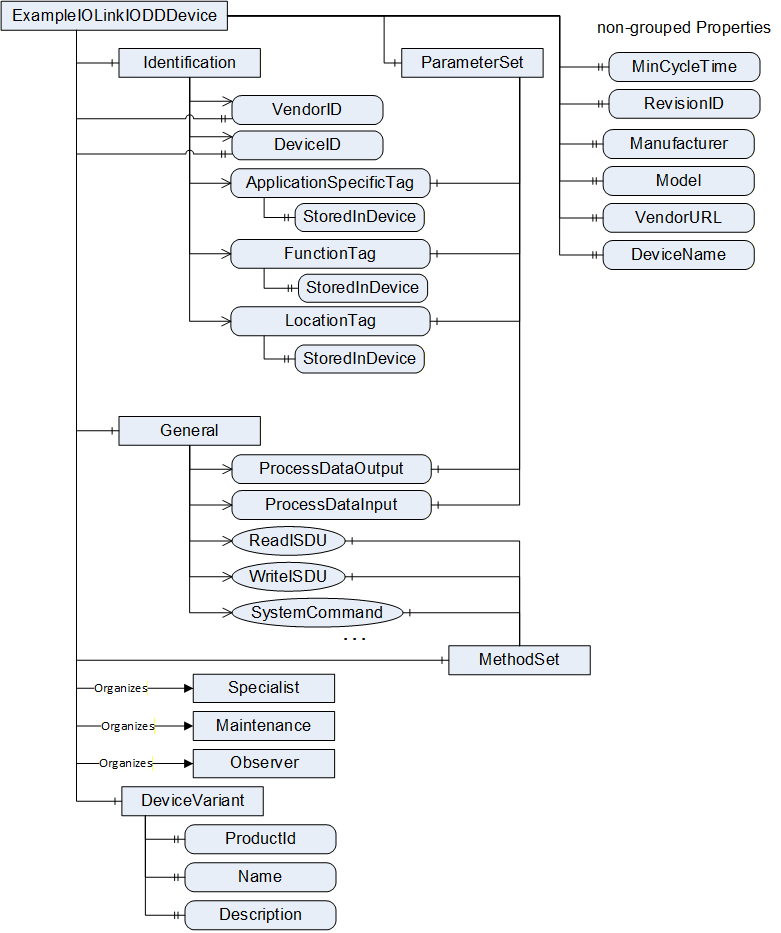
In Figure 12 an example of an instance of the IOLinkIODDDeviceType is shown. This example is using only the mandatory InstanceDeclarations, in order to give an overview on the ObjectType. Several Properties are directly connected to the Object, whereas the Parameters are connected via the ParameterSet, Methods via the MethodSet and both organized via different FunctionalGroups (Identification, General and Profiles).
7.2.3 Overview
The IOLinkIODDDeviceType provides the structure that all ObjectTypes generated based on IODDs have to provide and is formally defined in Table 17.
| Attribute | Value | |||||
| BrowseName | IOLinkIODDDeviceType | |||||
| IsAbstract | True | |||||
| References | Node Class | BrowseName | DataType | TypeDefinition | Modelling Rule | |
|---|---|---|---|---|---|---|
| Subtype of IOLinkDeviceType defined in 7.1. | ||||||
| HasComponent | Object | 2:ParameterSet | BaseObjectType | Mandatory | ||
| Organizes | Object | Specialist | FunctionalGroupType | Mandatory | ||
| Organizes | Object | Maintenance | FunctionalGroupType | Mandatory | ||
| Organizes | Object | Observer | FunctionalGroupType | Mandatory | ||
| HasComponent | Object | IODDInformation | FolderType | - | ||
| HasComponent | Object | DeviceVariants | FolderType | - | ||
| HasComponent | Object | DeviceVariant | DeviceVariantType | Mandatory | ||
| HasProperty | Variable | VendorURL | String | Property | Mandatory | |
| HasProperty | Variable | DeviceName | LocalizedText | Property | Mandatory | |
| HasProperty | Variable | VendorLogo | Image | Property | Optional | |
| HasComponent | Object | 2:DeviceTypeImage | FolderType | Optional | ||
The IOLinkIODDDeviceType ObjectType is an abstract type. Concrete subtypes are generated for concrete IODDs (see section 7.3 for details).
The mandatory Object ParameterSet is inherited from the supertype and overridden in order to add parameters defined in section 7.2.4.
The mandatory Object Specialist groups all menus of the SpecialistRoleMenuSet defined in an IODD.
The mandatory Object Maintenance groups all menus of the MaintenanceRoleMenuSet defined in an IODD.
The mandatory Object Observer groups all menus of the ObserverRoleMenuSet defined in an IODD.
The Object IODDInformation provides information about the IODD and is only provided on the ObjectType, not the instances of the ObjectType. Therefore, it does not have a ModellingRule. Its content is defined in 7.2.5.
The Object DeviceVariants provides information about the IO-Link Device variants supported by the ObjectType. It references all device variants (Objects of Type DeviceVariantType) with a HasComponent Reference. Device variants are defined by the subtypes of this ObjectType.
The mandatory Object DeviceVariant provides information about the currently used device variant on the instance.
The mandatory read-only Property VendorURL maps to the IODD DeviceIdentity/VendorURL element.
The mandatory read-only Property DeviceName maps to the IODD DeviceIdentity/DeviceName element. Localization should be considered. In IODD Specification Version 1.0.1 there is no IODD DeviceIdentity/DeviceName element defined. Instead of, the IODD DeviceVariant/ProductName element shall be used. Localization should be considered.
The optional read-only Property VendorLogo maps to the IODD DeviceIdentity/VendorLogo element, if the optional element is provided.
The optional Object DeviceTypeImage defined in OPC 10000-100 is overridden in order to reference Images of the DeviceVariant Object (see section 7.2.6).
7.2.4 Variables of the ParameterSet Object
In Table 18, the Variables of the ParameterSet Object of the IOLinkIODDDeviceType, are defined.
| References | Node Class | BrowseName | DataType | TypeDefinition | Modelling Rule |
| HasComponent | Variable | SupportedAccessLocks | Byte | OptionSetType | Optional |
The optional, read-only Variable SupportedAccessLocks maps to the IODD Features/SupportedAccessLocks element. The lowest bit of the Byte references to parameter, the next to dataStorage, the next to localParamaterization and the next to localUserInterface as defined in SupportedAccessLocksT. The OptionSetValues Property shall be filled with those names for locale "en". Servers might provide translations to other languages. In IODD Specification Version 1.0.1 there is no IODD Features/SupportedAccessLocks element. Therefore, the OPC UA Variable SupportedAccessLocks is not provided for IODDs following the IODD Specification Version 1.0.1.
7.2.5 Variables of the IODDInformation Object
In Table 19 the Variables of the IODDInformation Object of the IOLinkIODDDeviceType are defined.
| References | Node Class | BrowseName | DataType | TypeDefinition | Modelling Rule |
| HasProperty | Variable | Version | String | PropertyType | Mandatory |
| HasProperty | Variable | ReleaseDate | String | PropertyType | Mandatory |
| HasProperty | Variable | Copyright | String | PropertyType | Mandatory |
| HasProperty | Variable | IOLinkRevision | String | PropertyType | Mandatory |
The mandatory, read-only Property Version maps to the IODD DocumentInfo/@version attribute.
The mandatory, read-only Property ReleaseDate maps to the IODD DocumentInfo/@releaseDate attribute.
The mandatory, read-only Property Copyright maps to the IODD DocumentInfo/@copyright attribute.
The mandatory, read-only Property IOLinkRevision maps to the IODD ProfileHeader/ProfileRevision element.
7.2.6 Variables of the DeviceTypeImage Object
In Table 20, references of the DeviceTypeImage Object of the IOLinkIODDDeviceType, are defined.
| References | Node Class | BrowseName | DataType | TypeDefinition | Modelling Rule |
| HasComponent | Variable | DeviceIcon | References Variable DeviceIcon of DeviceVariant Object | ||
| HasComponent | Variable | DeviceSymbol | References Variable DeviceSymbol of DeviceVariant Object | ||
7.3 ObjectTypes generated based on IODDs
7.3.1 General
This clause defines how ObjectTypes shall be generated based on IODDs. For each IODD managed by the Server, the Server shall have an ObjectType as subtype of the IOLinkIODDDeviceType (see section 7.2).
The IsAbstract Attribute of the generated ObjectType shall be set to "False".
The BrowseName Attribute of the generated ObjectType shall be mapped to the IODD DeviceIdentity/DeviceName element using the default language. The DisplayName should use the localization provided by the DeviceName.
The optional Description Attribute is vendor-specific and might be omitted.
7.3.2 NodeId of generated ObjectTypes and their InstanceDeclarations
Each NodeId that is used to describe the generated ObjectTypes shall use the Namespace "http://opcfoundation.org/UA/IOLink/IODD" and the identifierType String. The String of the NodeId of the ObjectType shall be composed of the VendorId, the DeviceId (in DeviceIdentity) and the version of the IODD (in DocumentInfo) using the format: "<VendorId>|<DeviceId>|<version>" like "888|67335|V1.1". The InstanceDeclarations use this prefix followed by the BrowsePath. Variables and Methods, which might have several BrowsePaths use the BrowsePath coming from ParameterSet respectively MethodSet, Objects representing menus use the first BrowsePath that is defined in the IODD. The format is: "<ObjectTypeNodeId>||<BrowseName>[:<BrowseName>]". The BrowseName only contains the String part, not the NamespaceIndex. An example is "888|67335|V1.1||ParameterSet:V_LifeTimeYears" as string-part of the NodeId of a Variable.
Defining the NodeIds of ObjectTypes based on IODDs is necessary so that OPC UA Clients accessing different OPC UA Servers implementing this specification and using the same IODDs can identify that they actually deal with the same types.
7.3.3 Namespace of the BrowseNames
The BrowseNames used when generating ObjectTypes and their InstanceDeclarations shall use the Namespace "http://opcfoundation.org/UA/IOLink/IODD".
7.3.4 Mapping to InstanceDeclarations inherited from IOLinkIODDDeviceType
In general, on the instance all rules defined on the IOLinkIODDDeviceType or its supertypes shall apply. When a new ObjectType is created, some InstanceDeclarations of the supertype are overridden in order to provide information from the IODD like VendorId.
The VendorID shall be filled with the IODD DeviceIdentity/@vendorId.
The DeviceID shall be filled with the IODD DeviceIdentity/@deviceId.
The Manufacturer shall be filled with the IODD DeviceIdentity/@vendorName.
The VendorText shall be filled with the IODD DeviceIdentity/VendorText, taking the default language.
The DeviceClass shall be filled with the IODD DeviceIdentity/DeviceFamily.
7.3.5 Mapping of IODD Menus
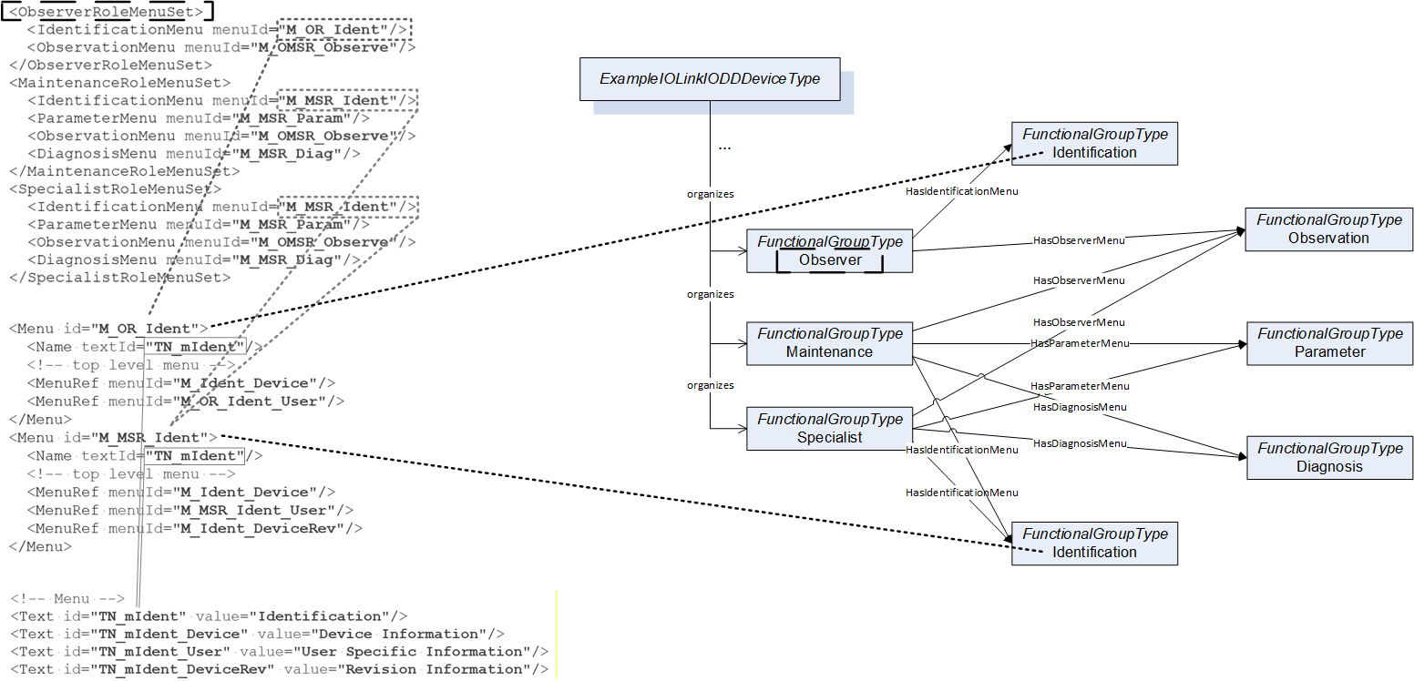
For each menu of the IODD UserInterface/MenuCollection that is referenced directly or indirectly form the IODD UserInterface/ObserverRoleMenuSet, the IODD UserInterface/MaintenanceRoleMenuSet or the IODD UserInterface/SpecialistRoleMenuSet, an Object of ObjectType FunctionalGroupType is created.
The BrowseName of the Object shall be the Id of the IODD Menu. The DisplayName shall be the Name of the IODD Menu. Localization should be considered. The optional Description Attribute is vendor-specific and might be omitted.
For each IdentificationMenu reference (UIMenuSimpleRefT) from the IODD UserInterface/ObserverRoleMenuSet, the IODD UserInterface/MaintenanceRoleMenuSet and the IODD UserInterface/SpecialistRoleMenuSet a HasIdentificationMenu Reference shall be created from the corresponding Object defined in section 7.2. The referenced Object shall have the ModellingRule Mandatory.
For each ParameterMenu reference (UIMenuSimpleRefT) from the IODD UserInterface/ObserverRoleMenuSet, the IODD UserInterface/MaintenanceRoleMenuSet and the IODD UserInterface/SpecialistRoleMenuSet a HasParameterMenu Reference shall be created from the corresponding Object defined in section 7.2. The referenced Object shall have the ModellingRule Mandatory.
For each ObservationMenu reference (UIMenuSimpleRefT) from the IODD UserInterface/ObserverRoleMenuSet, the IODD UserInterface/MaintenanceRoleMenuSet and the IODD UserInterface/SpecialistRoleMenuSet a HasObservationMenu Reference shall be created from the corresponding Object defined in section 7.2. The referenced Object shall have the ModellingRule Mandatory.
For each DiagnosisMenu reference (UIMenuSimpleRefT) from the IODD UserInterface/ObserverRoleMenuSet, the IODD UserInterface/MaintenanceRoleMenuSet and the IODD UserInterface/SpecialistRoleMenuSet an HasDiagnosisMenu Reference shall be created from the corresponding Object defined in section 7.2. The referenced Object shall have the ModellingRule Mandatory.
In Figure 13 an example of how to map IODD menus is shown. On the left, an excerpt of an IODD is shown, and on the right, the OPC UA representation.
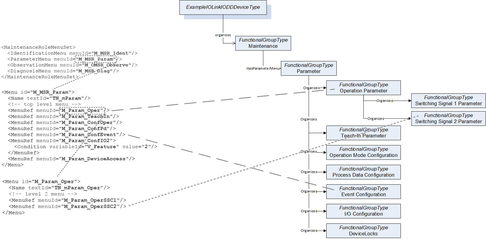
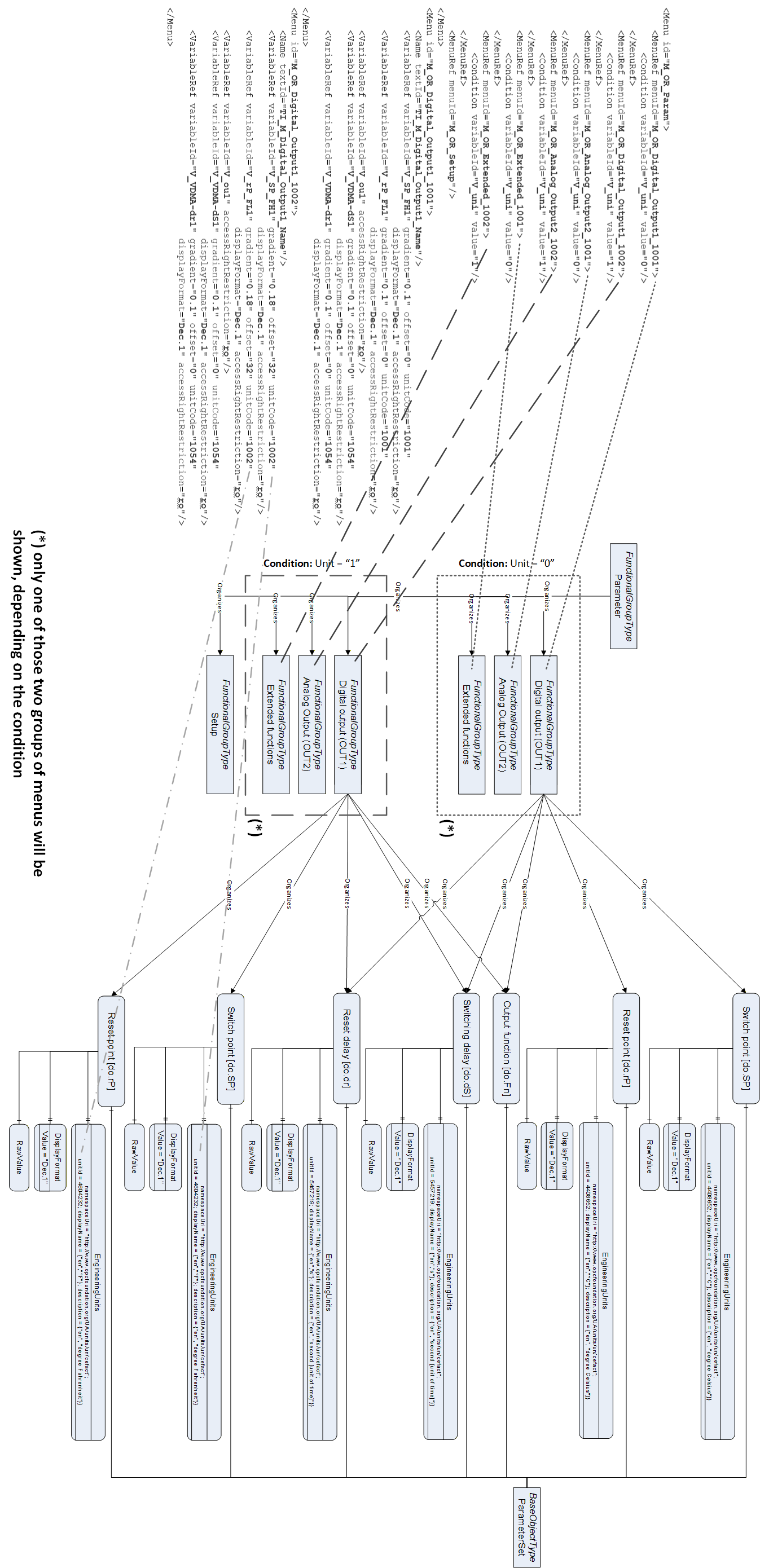
For each IODD Menu that has been added all MenuRefs shall reference the corresponding Objects with an Organizes Reference. If at least one IODD UIMenuRef does not provide an IODD MenuRef/Condition element, the ModellingRule shall be Mandatory, otherwise it shall be Optional.
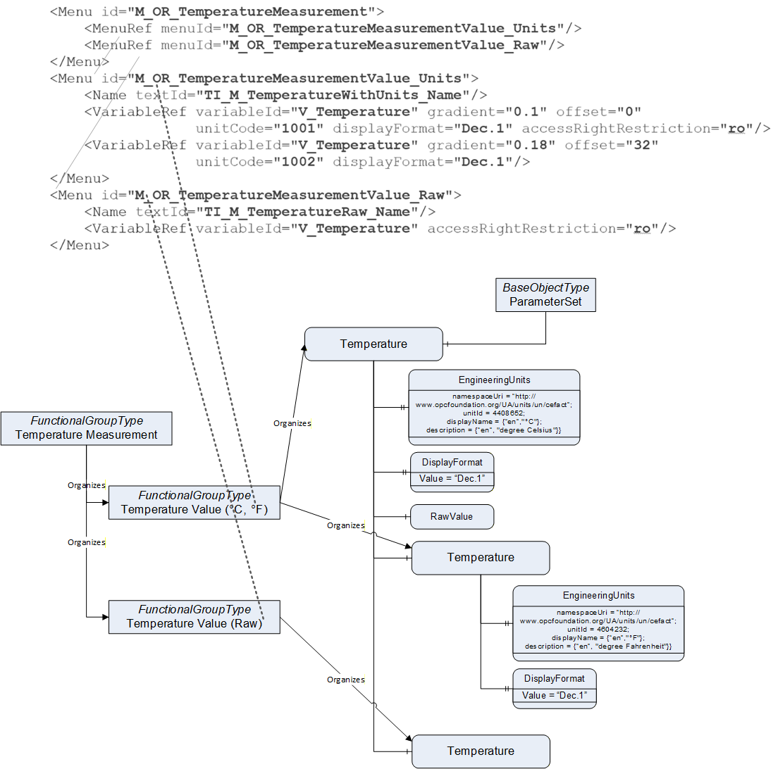
In Figure 14 another example of how to map IODD menus is shown. On the left, an excerpt of an IODD is shown, and on the right, the OPC UA representation. In this example, IODD Menus contain other IODD Menus.
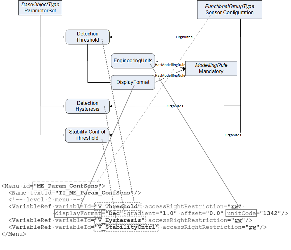
7.3.6 Mapping of IODD Variables
For each IODD Variable defined in the IODD an OPC UA Variable is created that is referenced from the ParameterSet with a HasComponent Reference. The ModellingRule shall be Mandatory for each of those Variables.
Each Object representing a menu referencing the Variable via a VariableRef not defining a Button shall reference the Variable with an Organizes Reference.
Each Object representing a menu referencing the Variable via a RecordItemRef not defining a Button shall reference the corresponding Sub-Variable with an Organizes Reference.
The BrowseName of the Variable shall be the Id of IODD Variable and the DisplayName the Name of the IODD Variable. Localization should be considered. The Description Attribute shall be the Description of IODD Variable. Localization should be considered.
The VariableType, DataType, ValueRank and ArrayDimensions are set according to section 12 depending on the Datatype or DatatypeRef. In addition, the VariableRef or RecordItemRef defines some characteristics that need to be considered.
If at least one VariableRef contains a unitCode the Variable shall have the Property EngineeringUnits. If more than one VariableRef references the IODD Variable and all VariableRefs contain the unitCode, the EngineeringUnits shall have the ModellingRule Mandatory, otherwise the ModellingRule Optional. The value of EngineeringUnits is vendor-specific because several VariableRefs might define different unitCodes. It might be omitted on the InstanceDeclaration.
If at least one VariableRef contains a displayFormat the Variable shall have the Property DisplayFormat (see section 13.6). If all VariableRefs contain the displayFormat, the DisplayFormat shall have the ModellingRule Mandatory, otherwise the ModellingRule Optional. The value of DisplayFormat is vendor-specific. It might be omitted on the InstanceDeclaration.
The same rules apply for the sub-variables referenced based on the RecordItemRefs.
The accessRightRestriction is ignored on the ObjectType and only considered on the instances.
In Figure 15 an example is shown of how to map IODD Variables referenced from an IODD Menu to OPC UA.
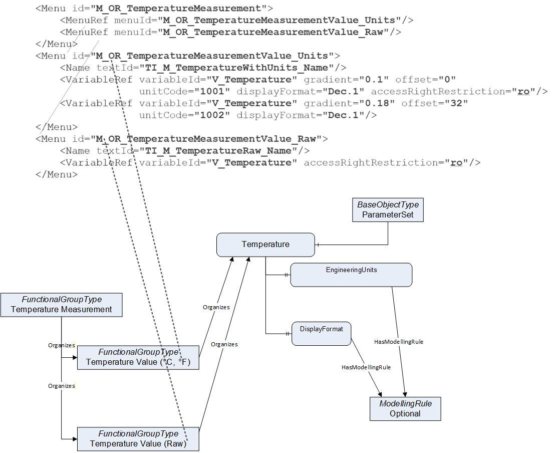
In Figure 16 another example is shown. In this example, the VariableRefs to the same IODD Variable contain different information.
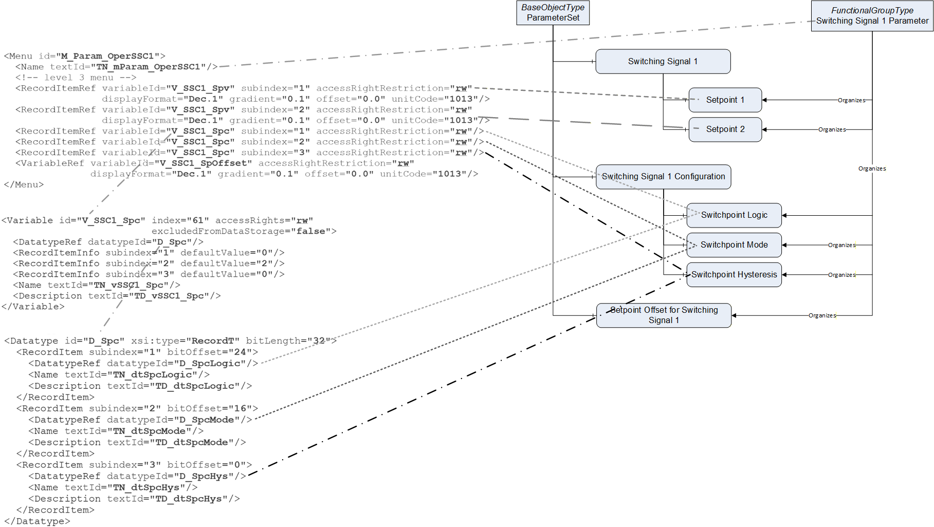
In Figure 17 an example on how to map RecordItemRefs is shown.
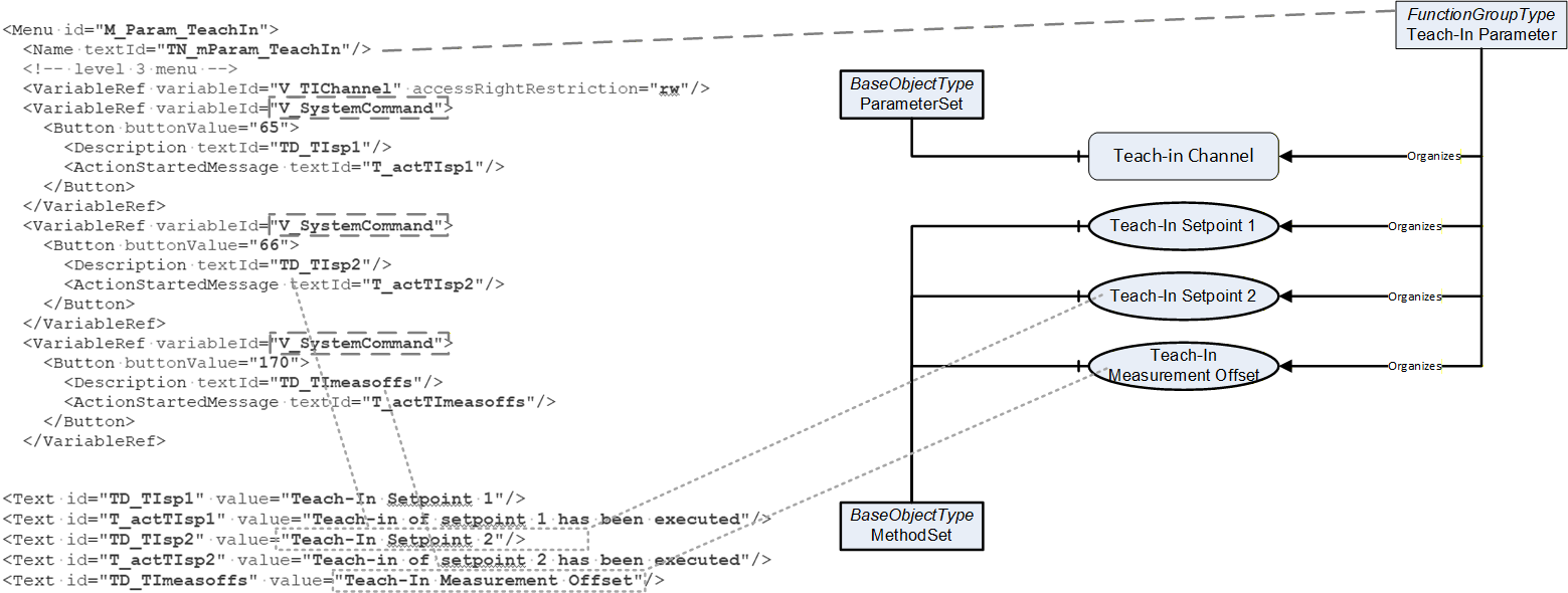
7.3.7 Mapping of Methods from IODD Menus
VariableRefs and RecordItemRefs can define Buttons. Those IODD Buttons are mapped to OPC UA Methods.
For each Button-defining VariableRef or RecordItemRef from an IODD Menu that is used in the mapping (see section 7.3.5) an OPC UA Method is created, that is referenced with a HasComponent Reference from the MethodSet Object.
In case several VariableRefs or RecordItemRefs have the same characteristics (Description, ActionStartedMessage, buttonValue, and in case of RecordItemRefs same subindex), only one Method is created.
The Objects representing the IODD Menus shall reference the corresponding Methods with Organizes References.
If at least one Object representing an IODD Menu referencing the Method has the ModellingRule Mandatory the Method shall have the ModellingRule Mandatory, otherwise Optional.
The BrowseName of the Method shall be the Id of the IODD Variable combined with the buttonValue. The format is "<Id>|<buttonValue>". In the unlikely case that the IODD Variable is referenced several times as Button with the same buttonValue but different other characteristics (Description and ActionStartedMessage), the additional Methods have a BrowseName postfixed by a number using the format "<Id>|<buttonValue>_<n>" where "n" is the occurrence in the order of the IODD, starting with a 2 for the second occurrence.
The DisplayName shall be the Description of the IODD Button, if a Description is provided. Localization should be considered. If no Description is provided, the DisplayName should be the BrowseName. The optional Description Attribute is vendor-specific and might be omitted.
The Methods shall not have input- or output-arguments. If the optional ActionStartedMessage of the IODD Button is provided, there shall be a Property with BrowseName "ActionStartedMessage" and the DataType String, providing the ActionStartedMessage of the IODD Button.
Note: The way a button is modelled inside an IODD VariableRef element changed from IODD Specification Version 1.0.1 to Version 1.1. The information modelled in IODD Specification Version 1.1 in the elements Description and ActionStartedMessage is not provided in IODD Specification Version 1.0.1.
The server-internal implementation of the Method shall implement the IODD Button according to the IODD Specification.
An example on how to map IODD Buttons to OPC UA Methods is shown in Figure 18.
7.3.8 Mapping of StdVariableRef and StdRecordItemRef
The StdVariableRefs (standard variable references) reference to standardized information, that is already defined in the IOLinkDeviceType. In Table 21, an overview of the mapping is given.
| StdVariableRef | InstanceDeclaration |
| V_SystemCommand | MethodSet/SystemCommand |
| V_DeviceAccessLocks | DeviceAccessLocks |
| V_VendorName | Manufacturer |
| V_VendorText | VendorText |
| V_ProductName | Model |
| V_ProductID | ProductID |
| V_ProductText | ProductText |
| V_SerialNumber | SerialNumber |
| V_HardwareRevision | DeviceRevision |
| V_FirmwareRevision | SoftwareRevision |
V_ApplicationSpecificTag (V_ApplicationSpecificName for IODDs based on IODD Specification 1.01) | ParameterSet/ApplicationSpecificTag |
| V_ErrorCount | ParameterSet/ErrorCount |
V_DeviceStatus (not defined in IODD Specification 1.01) | ParameterSet/DeviceHealth |
V_DetailedDeviceStatus (not defined in IODD Specification 1.01) | ParameterSet/DetailedDeviceStatus |
V_ProcessDataInput (V_ProcessDataIn for IODDs based on IODD Specification 1.01) | ParameterSet/ProcessDataInput |
V_ProcessDataOutput (V_PrcoessDataOut for IODDs based on IODD Specification 1.01) | ParameterSet/ProcessDataOutput |
| V_OffsetTime | ParameterSet/OffsetTime |
The StdRecordItemRefs (standard record item references) reference to standardized information, that is already defined in the IOLinkDeviceType. In Table 22, an overview of the mapping is given.
| StdRecordItemRef | InstanceDeclaration | |
| V_DirectParameters_1 | STD_TN_MasterCycleTime | - |
| V_DirectParameters_1 | STD_TN_MinCycleTime | MinCycleTime |
| V_DirectParameters_1 | STD_TN_M-SequenceCapability | - |
| V_DirectParameters_1 | STD_TN_RevisionID | RevisionID |
| V_DirectParameters_1 | STD_TN_ProcessDataIn | ParameterSet/ProcessDataInput/ProcessDataLength |
| V_DirectParameters_1 | STD_TN_ProcessDataOut | ParameterSet/ProcessDataOutput/ProcessDataLength |
| V_DirectParameters_1 | STD_TN_VendorID1 | VendorID |
| V_DirectParameters_1 | STD_TN_VendorID2 | VendorID |
| V_DirectParameters_1 | STD_TN_DeviceID1 | DeviceID |
| V_DirectParameters_1 | STD_TN_DeviceID2 | DeviceID |
| V_DirectParameters_1 | STD_TN_DeviceID3 | DeviceID |
| V_DirectParameters_1 | STD_TN_SystemCommand | - |
| V_DirectParameters_2 | STD_TN_DeviceSpecific_1 | - |
| V_DirectParameters_2 | STD_TN_DeviceSpecific_2 | - |
| V_DirectParameters_2 | STD_TN_DeviceSpecific_3 | - |
| V_DirectParameters_2 | STD_TN_DeviceSpecific_4 | - |
| V_DirectParameters_2 | STD_TN_DeviceSpecific_5 | - |
| V_DirectParameters_2 | STD_TN_DeviceSpecific_6 | - |
| V_DirectParameters_2 | STD_TN_DeviceSpecific_7 | - |
| V_DirectParameters_2 | STD_TN_DeviceSpecific_8 | - |
| V_DirectParameters_2 | STD_TN_DeviceSpecific_9 | - |
| V_DirectParameters_2 | STD_TN_DeviceSpecific_10 | - |
| V_DirectParameters_2 | STD_TN_DeviceSpecific_11 | - |
| V_DirectParameters_2 | STD_TN_DeviceSpecific_12 | - |
| V_DirectParameters_2 | STD_TN_DeviceSpecific_13 | - |
| V_DirectParameters_2 | STD_TN_DeviceSpecific_14 | - |
| V_DirectParameters_2 | STD_TN_DeviceSpecific_15 | - |
| V_DirectParameters_2 | STD_TN_DeviceSpecific_16 | - |
In both cases, the following rule applies.
If there is an InstanceDeclaration on the IOLinkDeviceType:
If the StdVariableRef or StdRecordItemRef is not defining a Button and the InstanceDeclaration is a Variable, the InstanceDeclaration shall be overridden in the new created type and referenced from all Objects representing IODD Menus having such a reference. If a default value is defined, the OPC UA Server shall use this as Value of the Variable, if several different default values are defined, the first one defined in the IODD shall be used. Other characteristics defined on the StdVariableRef of StdRecordItemRef are ignored.
For VendorID and DeviceID there are two resp. three StdRecordItemRefs used. In the mapping, whenever an IODD Menu references at least one of them, the whole Variable (VendorID or DeviceID) is referenced.
If the StdVariableRef or StdRecordItemRef is defining a Button, the rules defined in 7.3.7 apply.
If there is no InstanceDeclaration on the IOLinkDeviceType defined, the same rules as for VariableRef and RecordItemRef defined in 7.3.6 and 7.3.7 apply.
Note that for V_SystemCommand the mapping described in this section applies, although there is a representation in the IOLinkDeviceType (SystemCommand Method), because the IODD provides useful new information about the supported system commands.
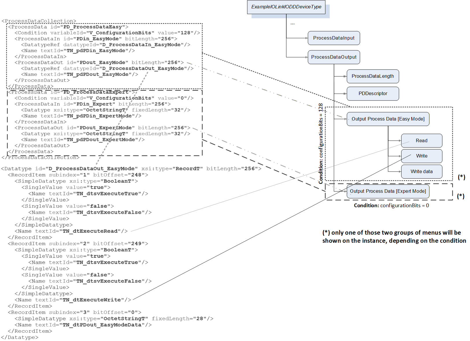
7.3.9 Mapping of ProcessDataCollection and ProcessDataRefCollection
The ProcessDataCollection gives an interpretation of the input and / or output process data.
For each entry of the collection (IODD ProcessData) having an IODD ProcessDataOut of type ProcessDataItemT, for each IODD ProcessDataOut, a new sub-variable of the OPC UA Variable ProcessDataOutput is created, having the BrowseName composed of the ProcessData id and the ProcessDataItem id ("<ProcessData id>|<ProcessDataItem id>"). If the ProcessData has a Condition, the Variable becomes optional, otherwise mandatory. In order to add a sub-variable to the ProcessDataOutput Variable defined on the IOLinkDeviceType, the ProcessDataOutput Variable needs to be overridden on the new created IODD-based subtype.
For each entry of the collection (IODD ProcessData) having a ProcessDataIn of type ProcessDataItemT, for each ProcessDataIn, a new sub-variable of ProcessDataInput is created, having the BrowseName composed of the ProcessData id and the ProcessDataItem id ("<ProcessData id>|<ProcessDataItem id>"). If the ProcessData has a Condition, the Variable becomes optional, otherwise mandatory. In order to add a sub-variable to the ProcessDataInput Variable defined on the IOLinkDeviceType, the ProcessDataInput Variable needs to be overridden on the new created IODD-based subtype.
In both cases the DisplayName shall be the Name element of the ProcessDataItem. Localization should be considered. The DataType is chosen for the Datatype element or DatatypeRef element according to section 12.
The ProcessDataRefCollection can provide additional characteristics for the created Variables, like unitCode and displayFormat. Note that the optional ProcessDataRefCollection and its child elements are not supported by IODD Specification Version 1.0.1.
If the ProcessDataRef contains a unitCode the Variable shall have the Property EngineeringUnits as mandatory. The value shall be as defined in the ProcessDataRef (see Annex C).
If the ProcessDataRef contains a displayFormat the Variable shall have the Property DisplayFormat (see 13.6) as mandatory. The value shall be as defined in the ProcessDataRef.
In Figure 19 an example is shown on how to map an IODD ProcessDataCollection.
7.3.10 Mapping of DirectParameterOverlay
In case the DirectParameterOverlay is defined in the IODD, the mapping shall be the same as for Variables with respect to the DataType (RecordT). The BrowseName shall be "DirectParameterPage2", and the DisplayName the same for locale "en" and might provide translations. A vendor-specific Description might be provided.
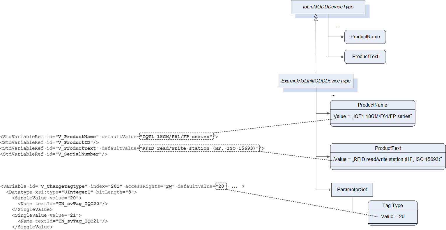
7.3.11 Mapping of Default Values
In different places of the IODD default values can be defined.
The DirectParameterOverlay can define default values for the individual entries
The StdVariableRef can define default values
The Variable can define default values
The RecordItemInfo and StdRecordItemRef can define default values
In all cases the default value shall be provided as value of the corresponding Variables on the ObjectType. In case of StdVariableRefs the Variables are already defined in the supertype and need to be overridden on the IODD-based type in order to provide the default value.
An example on how to map DefaultValues is shown in Figure 20.
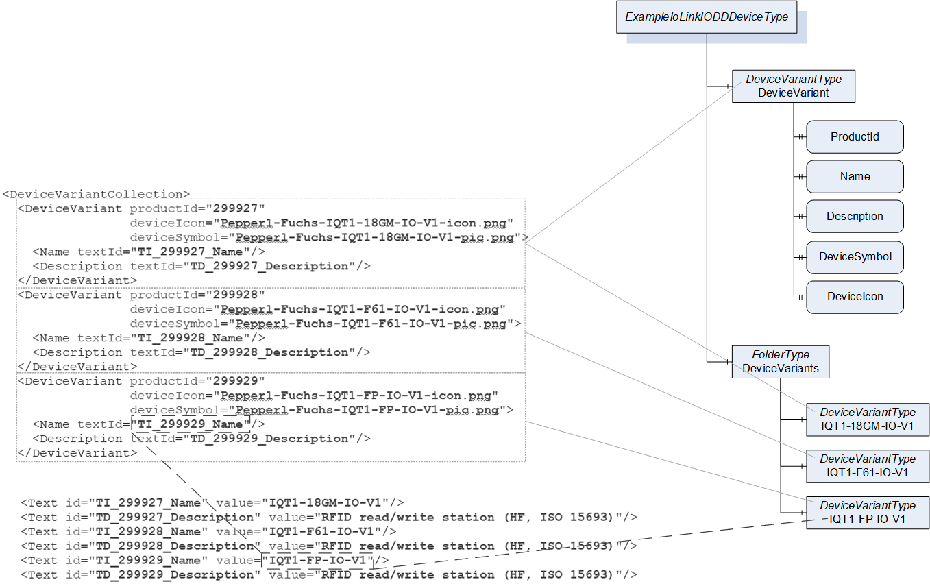
7.3.12 Mapping of DeviceVariantCollection
All entries of the DeviceVariantCollection are mapped to instances of DeviceVariantType according to section 7.7. The Objects are referenced from the DeviceVariants Object with a HasComponent Reference.
The first entry of the DeviceVariantCollection is also mapped to the DeviceVariant Object.
In Figure 21 an example is given.
7.3.13 Mapping of EventCollection
Information about Events (Notification) is not mapped to additional EventTypes, but the IOLinkIODDDeviceEventType is used.
When an IO-Link Device sends a Notification, and the server manages the IODD for the IO-Link Device, an Event of the IOLinkIODDDeviceEventType is generated according to the EventType definition.
Information about Alarms (Warning and Error) is not mapped to additional EventTypes, but the IOLinkIODDDeviceAlarmType is used. If the OPC UA server supports Alarm Objects represented in the AddressSpace, the server may provide the Alarms Object on the ObjectType and provide all possible Alarms as Objects based on the IODD.
When an IO-Link Device sends a Warning or Error, and the server manages the IODD for the IO-Link Device, an Event of the IOLinkIODDDeviceAlarmType is generated according to the EventType definition.
7.4 Creation of Instances based on ObjectTypes generated out of IODDs
When an instance is created based on an ObjectType generated out of an IODD, two scenarios need to be considered.
Either an IO-Link Device is connected and thus conditions can be evaluated or
no IO-Link Device is connected but the IO-Link Port is configured in IOL_MANUAL (see section 6.1.7).
In the second case all optional Objects, Variables and Methods are omitted and only the mandatory Objects, Variables and Methods are provided. Except for VendorID and DeviceID, which shall expose the configured DeviceID and VendorID on the IO-Link Port, all Variables cannot be read or written and all Methods cannot be executed. The server shall report a Bad_NoCommunication StatusCode in those cases.
In the first case the Conditions on the MenuRefs and ProcessData are evaluated and the Objects and Variables are only provided when they are referenced (either directly or indirectly) based on the Condition evaluation.
Some characteristics of a Variable like the unitCode (see Annex C), displayFormat (see section 13.6) and additional accessRightRestriction are defined in the VariableRef of the IODD. A Variable can be referenced by several VariableRefs. Typically, in an IODD all valid VariableRefs (from menus which are active based on the Condition) to the same Variable use the same characteristics. But this is not required. Since the characteristics are exposed in OPC UA on the Variable, and not the reference to the Variable, the following rules apply for creating an instance.
The Variable referenced from the ParameterSet Object uses the characteristics as defined by the first active menu in the MenuCollection of the IODD. For a VariableRef with different characteristics a new Variable is defined referenced by the initially created Variable with a HasComponent Reference. It provides the different characteristics and uses the same BrowseName and mapping as the initial Variable. All VariableRefs that have characteristics that already have a Variable representing the characteristics shall reference that Variable.
In addition to the AccessLevel defined in section 12, the accessRightRestriction of the VariableRef and the accessRights on the IODD Variable shall be considered. Also, the offset and gradient to change the raw value coming from the IO-Link Device shall be considered.
In case the raw value is changed in the Variable (offset and/or gradient are defined in the IODD), there shall be a Sub-Variable on the OPC UA Variable instance with the BrowseName "RawValue" providing the raw value from the IO-Link Device.
When the IODD provides default values for a Variable in OPC UA, and the server has not already read the value from the IO-Link Device, the default value should be provided with StatusCode Uncertain_InitialValue.
The DeviceVariant Object is filled with the DeviceVariant according to the ProductID of the IO-Link Device. If the IO-Link Device does not provide this optional parameter or ProductID does not correspond to a DeviceVariant specified in the IODD, the OPC UA Server shall use the first DeviceVariant defined in the IODD.
If the optional DeviceSymbol or DeviceIcon Variable exist on the DeviceVariant Object, the DeviceTypeImage Folder defined in OPC 10000-100 shall be provided. The DeviceTypeImage Folder shall reference the DeviceSymbol and the DeviceIcon with a HasComponent Reference if those Variables are provided on the DeviceVariant Object.
When the blockParameter attribute is defined and set to "False" in the IODD, the Methods ParamUploadFromDeviceStart, ParamUploadFromDeviceStop, ParamDownloadToDeviceStart, ParamDownloadToDeviceStop, and ParamBreak shall have the Executable Attribute set to "False".
When the dataStorage attribute is defined and set to "False" in the IODD, the Method ParamDownloadToDeviceStore shall have the Executable Attribute set to "False".
In Figure 22 an example of an Object based on an IODD is shown.
In Figure 23, an example of an Object based on an IODD is shown, where an IODD Variable is referenced by VariableRefs with different characteristics.
7.5 IOLinkMasterType ObjectType Definition
7.5.1 Example
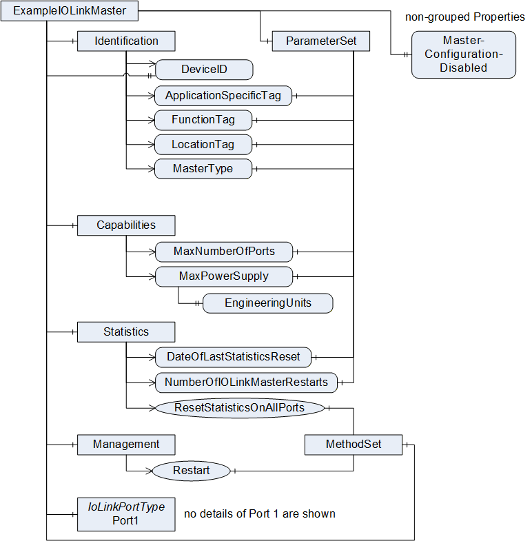
In Figure 24 an example of an instance of the IOLinkMasterType is shown. The example is using only the mandatory InstanceDeclarations, in order to give an overview on the ObjectType. Several Properties are directly connected to the Object, whereas the Parameters are connected via the ParameterSet, Methods via the MethodSet and both are organized via different FunctionalGroups (Identification, Capabilities, Statistics and Management).
7.5.2 Overview
The IOLinkMasterType provides information of an IO-Link Master and is formally defined in Table 23.
| Attribute | Value | ||||
| BrowseName | IOLinkMasterType | ||||
| IsAbstract | False | ||||
| References | Node Class | BrowseName | DataType | TypeDefinition | Modelling Rule |
|---|---|---|---|---|---|
| Subtype of TopologyElementType defined in OPC 10000-100. | |||||
| HasComponent | Object | 2:ParameterSet | BaseObjectType | Mandatory | |
| HasComponent | Object | 2:MethodSet | BaseObjectType | Mandatory | |
| HasComponent | Object | 2:Identification | FunctionalGroupType | Mandatory | |
| HasComponent | Object | Capabilities | FunctionalGroupType | Mandatory | |
| HasComponent | Object | Management | FunctionalGroupType | Mandatory | |
| HasComponent | Object | Statistics | FunctionalGroupType | Mandatory | |
| HasProperty | Variable | DeviceID | UInt32 | PropertyType | Mandatory |
| HasProperty | Variable | ProductID | String | PropertyType | Optional |
| HasProperty | Variable | ProductText | String | PropertyType | Optional |
| HasProperty | Variable | RevisionID | String | PropertyType | Optional |
| HasProperty | Variable | VendorID | UInt16 | PropertyType | Optional |
| HasProperty | Variable | VendorURL | String | PropertyType | Optional |
| HasProperty | Variable | IOLinkStackRevision | String | PropertyType | Optional |
| HasProperty | Variable | MasterConfigurationDisabled | Boolean | PropertyType | Mandatory |
| HasComponent | Object | Port<n> | IOLinkPortType | Mandatory‑Placeholder | |
| HasComponent | Object | Alarms | FolderType | Optional | |
| GeneratesEvent | ObjectType | IOLinkMasterEventType | Defined in 9.6. | ||
| GeneratesEvent | ObjectType | IOLinkMasterAlarmType | Defined in 9.11. | ||
The IOLinkMasterType ObjectType is a concrete type and can be used directly. Vendors may create subtypes of the IOLinkMasterType to add vendor-specific extensions.
The ObjectType inherits the following InstanceDeclarations directly or indirectly from the TopologyElementType defined in OPC 10000-100.
The optional Object ParameterSet is used to reference all Parameters and shall be provided. Therefore, the ObjectType overrides the Object and changes the ModellingRule to Mandatory.
The optional Object MethodSet is used to reference all Methods and shall be provided. Therefore, the ObjectType overrides the Object and changes the ModellingRule to Mandatory.
The optional Object Identification shall be provided and shall reference the Parameters defined in Table 24. Those Parameters together uniquely identify the IO-Link Master (see OPC 10000-100 for details). Therefore, the ObjectType overrides the Object and changes the ModellingRule to Mandatory.
| References | BrowseName | Comment |
| Organizes | DeviceID | Variable defined in Table 23. |
| Organizes | VendorID | Variable defined in Table 23. |
| Organizes | ApplicationSpecificTag | Variable defined in Table 28. |
| Organizes | FunctionTag | Variable defined in Table 28. |
| Organizes | LocationTag | Variable defined in Table 28. |
| Organizes | MasterType | Variable defined in Table 28. |
The Object <GroupIdentifier> has the ModellingRule OptionalPlaceholder and is intended to group the Parameters. It is already used in this ObjectType by adding the Objects Capabilities, Management and Statistics. Vendors may add vendor-specific Objects to group additional Parameters.
The optional Object Lock can be supported by a server to provide locking capabilities (see OPC 10000-100 for details). This is intended to prevent different clients and users to configure an IO-Link Master at the same time. Locking an IOLinkMasterType Object includes locking all its ports and the IOLinkDeviceType Objects connected to the ports.
The ObjectType defines additional InstanceDeclarations:
The mandatory Object Capabilities shall reference the Parameters defined in Table 25. Servers may add vendor-specific Parameters or Methods to this Object.
| References | BrowseName | Comment |
| Organizes | MaxNumberOfPorts | Variable defined in Table 28. |
| Organizes | MaxPowerSupply | Variable defined in Table 28. |
The mandatory Object Management shall reference the Methods defined in Table 26. Servers may add vendor-specific Parameters or Methods to the Object.
| References | BrowseName | Comment |
| Organizes | Restart | Method defined in Table 30. |
The mandatory Object Statistics shall reference the Parameters and Methods defined in Table 26. Servers may add vendor-specific Parameters or Methods to the Object.
| References | BrowseName | Comment |
| Organizes | ResetStatisticsOnAllPorts | Method defined in Table 30. |
| Organizes | NumberOfIOLinkMasterStarts | Variable defined in Table 28. |
| Organizes | DateOfLastStatisticsReset | Variable defined in Table 28. |
The mandatory, read-only Variable DeviceID shall be mapped to MasterID of the MasterIdent structure defined in the SMI (see IO-Link Addendum). The value (three bytes) shall be mapped to an UInt32, using Big Endian.
The optional, read-only Variable ProductID provides a vendor-specific product or type identification like the ProductID of the IOLinkDeviceType. The implementation is vendor-specific.
The optional, read-only Variable ProductText provides additional, vendor-specific product information like the ProductText of the IOLinkDeviceType. The implementation is vendor-specific.
The optional, read-only Variable RevisionID contains the IO-Link protocol version supported by the IO-Link Master, like the RevisionID of the IOLinkDeviceType. The same rules as defined for RevisionID in IOLinkDeviceType apply (see section 7.1).
The optional, read-only Variable VendorID of type UInt16 shall be mapped to VendorID of the MasterIdent structure defined in the SMI (see IO-Link Addendum), using the same type.
The optional Variable VendorURL provides a link to the website of the vendor of the IO-Link Master. The implementation is vendor-specific.
The optional read-only Variable IOLinkStackRevision provides the revision of the IO-Link stack implementation used by the IO-Link Master. The implementation is vendor-specific.
The mandatory Variable MasterConfigurationDisabled indicates whether configuration changes are allowed via OPC UA. If set to "True", nearly all configuration settings become read-only and cannot be changed via OPC UA anymore. The Variable setting is vendor-specific, including whether it can be changed via OPC UA. For example, if a fieldbus is currently active on the IO-Link Master, a server might set this Variable to "True".
That includes in detail following rules:
The Method Restart of the IO-Link Master becomes not executable.
For all Ports of the IO-Link Master the Method UpdateConfiguration becomes not executable.
For all Ethernet configurations connected to the Fieldbus the configuration becomes read-only.
The Method ResetStatistics on the Port and ResetStatisticsOnAllPorts on the IO-Link Master shall still be executable.
There is no direct relation between the MasterConfigurationDisabled Variable and the Lock Object. The Lock Objects prevents different OPC UA Clients to configure the IO-Link Master at the same time whereas the MasterConfigurationDisabled Variable indicates that the IO-Link Master is in a state within it cannot be configured by any OPC UA Client. When the MasterConfigurationDisabled Variable is set to "True" Servers may prevent the usage of the Lock Object for all Clients.
The Port<n> Object of ModellingRule MandatoryPlaceholder represents the ports of the IO-Link Master. For each port of the IO-Link Master one Object of type IOLinkPortType shall be provided, where <n> represents the number of the port. For example, a master having two ports has the Objects Port1 and Port2. How the counting starts (e.g. Port0 or Port1) is vendor-specific.
The optional Alarms Object is used to group all alarms of the instance, in case the server supports representing the alarms as Objects in the AddressSpace. If the server does not support this, the Object shall not be provided.
7.5.3 Variables of ParameterSet
In Table 28, the Parameters of the ObjectType, referenced via the ParameterSet Object, are defined.
| References | Node Class | BrowseName | DataType | TypeDefinition | Modelling Rule |
| The following Parameters are also referenced by the Capabilities Object | |||||
| HasComponent | Variable | MaxNumberOfPorts | Byte | BaseDataVariableType | Mandatory |
| HasComponent | Variable | MaxPowerSupply | Double | BaseDataVariableType | Mandatory |
| The following Parameters are also referenced by the Identification Object | |||||
| HasComponent | Variable | ApplicationSpecificTag | String | BaseDataVariableType | Mandatory |
| HasComponent | Variable | FunctionTag | String | BaseDataVariableType | Mandatory |
| HasComponent | Variable | LocationTag | String | BaseDataVariableType | Mandatory |
| HasProperty | Variable | MasterType | Byte | MultiStateDiscreteType | Mandatory |
| The following Parameters are also referenced by the Statistics Object | |||||
| HasComponent | Variable | DateOfLastStatisticsReset | DateTime | BaseDataVariableType | Optional |
| HasComponent | Variable | NumberOfIOLinkMasterStarts | UInt32 | BaseDataVariableType | Optional |
The mandatory, read-only Variable MaxNumberOfPorts shall be mapped to MaxNumberOfPorts of the MasterIdent structure defined in the SMI interface (see IO-Link Addendum).
The mandatory, read-only Variable MaxPowerSupply shall provide the overall amount of power provided together on all ports of the IO-Link Master in ampere. For example, a 4-port IO-Link Master may provide max. 2 A on each port but an overall MaxPowerSupply of 6 A, so not each port can consume 2 A at the same time. The Variable shall provide the EngineeringUnits Property defined in OPC 10000-3, having the value set to {namespaceUri = "http://www.opcfoundation.org/UA/units/un/cefact"; unitId = 4279632; displayName = {"en","A"}; description = {"en", "ampere"}} (for ampere). The Property shall be read-only and have the ModellingRule Mandatory, so it is reflected on all instances.
The mandatory, writeable Variable ApplicationSpecificTag provides the same information as the ApplicationSpecificTag defined for an IO-Link Device on the IO-Link Master level. The server shall manage the value in a persistent manner. If a fieldbus mapping of the IO-Link Master exists providing the same information, consistency shall be provided by the OPC UA Server.
The mandatory, writeable Variable FunctionTag provides the same information as the FunctionTag defined on an IO-Link Device on the IO-Link Master level. The server shall manage the value in a persistent manner. If a fieldbus mapping of the IO-Link Master exists providing the same information, consistency shall be provided by the OPC UA Server.
The mandatory, writeable Variable LocationTag provides the same information as the LocationTag defined for an IO-Link Device on the IO-Link Master level. The server shall manage the value in a persistent manner. If a fieldbus mapping of the IO-Link Master exists providing the same information, consistency shall be provided by the OPC UA Server.
The mandatory, read-only Variable MasterType shall be mapped to MasterType of the MasterIdent structure defined in the SMI (see IO-Link Addendum). The Unsigned8 is mapped directly to the DataType Byte. The Variable is of VariableType MultiStateDiscreteType defined in OPC 10000-8. The mandatory Property EnumStrings of the VariableType, which is an array of LocalizedText, shall contain the content as defined in Table 29.
| Element number (starting with 0) | Message (for locale "en") |
| 0 | Unspecific |
| 1 | Master acc. V1.0 |
| 2 | Master acc. V1.1 |
Servers are allowed to add additional entries into the EnumStrings array. Servers may provide translations of the texts in different locales.
The optional, read-only Variable DateOfLastStatisticsReset contains the timestamp of the answer to the last call of the Method ResetStatisticsOnAllPorts. The timestamp information shall be as precise as possible. If the ResetStatisticsOnAllPorts Method was never called then DateOfLastStatisticsReset indicates the startup time. The optional Variable shall be provided when the optional Method ResetStatisticsOnAllPorts is provided.
The following Variable indicates the incidents since DateOfLastStatisticsReset. The server should persist statistics, also when the IO-Link Master or the OPC UA Server is restarted. However, if the statistics become inconsistent, the server is allowed to do an internal reset. This will result in the update of DateOfLastStatisticsReset. If the value of a counting Variable becomes larger than the maximum value of the DataType, the value shall remain on the maximum value.
The optional, read-only Variable NumberOfIOLinkMasterStarts indicates how often the IO-Link Master was started since DateOfLastStatisticsReset. This includes starts on power up as well as warm starts and restarts due to errors. This variable is reset with the Method ResetStatisticsOnAllPorts to 0. When the IO-Link Master starts for the very first time, the value is 1 as it has started once.
7.5.4 Methods of MethodSet
In Table 30, the Methods of the ObjectType, referenced via the MethodSet Object are defined.
| References | Node Class | BrowseName | Modelling Rule |
| The following Methods are also referenced by the Management Object | |||
| HasComponent | Method | Restart | Mandatory |
| The following Methods are also referenced by the Statistics Object | |||
| HasComponent | Method | ResetStatisticsOnAllPorts | Optional |
7.5.4.1 Restart
The Method Restart restarts the IO-Link Master.
Signature
	Restart (
		[in]	Duration		Delay,
		[out]	Int32			Status
		);
| Argument | Description |
| Delay | Time before the restart becomes effective. |
| Status | Returns the status of the operation. 0: OK, operation successful -1: Operation already running -2: Operation cannot be executed -3: Operation cannot be executed because master reconfiguration is disabled. |
7.5.4.2 ResetStatisticsOnAllPorts
The optional Method ResetStatisticsOnAllPorts resets all statistic data, including statistic data of the ports of the IO-Link Master. Statistic data of a port are all Parameters referenced by the Statistics Object of the IOLinkPortType Object starting with "NumberOf" and potentially vendor-specific extensions. Statistic data directly on the IO-Link Master includes the Variable NumberOfIOLinkMasterStarts and potential vendor-specific extensions. As soon as statistic data is provided by the server, the optional Method shall be provided.
Signature
	ResetStatisticsOnAllPorts (
		[out]	Int32			Status
		);
| Argument | Description |
| Delay | Time before the reset becomes effective. |
| Status | Returns the status of the operation. 0: OK, operation successful -1: Operation already running -2: Operation cannot be executed. |
7.6 IOLinkPortType ObjectType Definition
7.6.1 Example
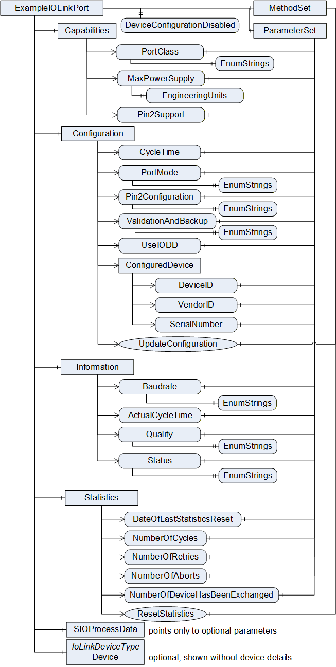
In Figure 25 an example of an instance of the IOLinkPortType is shown, using only the mandatory InstanceDeclarations, in order to give an overview on the ObjectType. The Object does not have Properties, its Parameters are connected via the ParameterSet, Methods via the MethodSet and both organized via different FunctionalGroups (Capabilities, Statistics, SIOProcessData, Configuration (containing another FunctionalGroup ConfiguredDevice), and Information). Note that SIOProcessData only points to optional Parameters not used in this example.
7.6.2 Overview
The IOLinkPortType provides information of one port of an IO-Link Master and is formally defined in Table 8.
| Attribute | Value | ||||
| BrowseName | IOLinkPortType | ||||
| IsAbstract | False | ||||
| References | Node Class | BrowseName | DataType | TypeDefinition | Modelling Rule |
|---|---|---|---|---|---|
| Subtype of TopologyElementType defined in OPC 10000-100. | |||||
| HasComponent | Object | 2:ParameterSet | BaseObjectType | Mandatory | |
| HasComponent | Object | 2:MethodSet | BaseObjectType | Mandatory | |
| HasProperty | Variable | DeviceConfigurationDisabled | Boolean | PropertyType | Mandatory |
| HasComponent | Object | Capabilities | FunctionalGroupType | Mandatory | |
| HasComponent | Object | Information | FunctionalGroupType | Mandatory | |
| HasComponent | Object | Statistics | FunctionalGroupType | Mandatory | |
| HasComponent | Object | Configuration | FunctionalGroupType | Mandatory | |
| HasComponent | Object | SIOProcessData | FunctionalGroupType | Mandatory | |
| HasComponent | Object | Device | IOLinkDeviceType | Optional | |
| HasComponent | Object | Alarms | FolderType | Optional | |
| GeneratesEvent | ObjectType | IOLinkPortEventType | Defined in 9.5. | ||
| GeneratesEvent | ObjectType | IOLinkPortAlarmType | Defined in 9.10 | ||
The IOLinkPortType ObjectType is a concrete type and can be used directly. Vendors may create subtypes of the IOLinkPortType to add vendor-specific extensions.
The ObjectType inherits the following InstanceDeclarations directly or indirectly from the TopologyElementType defined in OPC 10000-100.
The optional Object ParameterSet is used to reference all Parameters and shall be provided. Therefore, the ObjectType overrides the Object and changes its ModellingRule to Mandatory.
The optional Object MethodSet is used to reference all Methods and shall be provided. Therefore, the ObjectType overrides the Object and changes its ModellingRule to Mandatory.
The optional Object Identification is not used in this ObjectType.
The Object <GroupIdentifier> has the ModellingRule OptionalPlaceholder and is intended to group the Parameters. It is already used in this ObjectType by adding various FunctionalGroupType Objects. Vendors may add vendor-specific Objects to group additional Parameters.
The optional Object Lock can be supported by a server to provide locking capabilities (see OPC 10000-100 for details). This is intended to prevent different clients and users to configure an IO-Link Master at the same time. Locking the Port also locks the connected IO-Link Device.
The ObjectType defines additional InstanceDeclarations:
The mandatory Variable DeviceConfigurationDisabled indicates whether configuration changes of the connected IO-Link Device (Device Object) are allowed via OPC UA. If set to "True", nearly all configuration settings become read-only and cannot be changed via OPC UA anymore. The Variable setting is vendor-specific, including whether it can be changed via OPC UA. For example, if a fieldbus is currently active on the IO-Link Master, a server might set this Variable to "True" on all its ports.
That includes in detail following rules:
For the IO-Link Device connected to the IO-Link Port (Device Object) all Parameters become read-only.
For the IO-Link Device connected to the IO-Link Port (Device Object) all Methods defined in the IOLinkDeviceType except ReadISDU become not executable.
For the IO-Link Device connected to the IO-Link Port (Device Object) all Methods created based on the IODD become not executable unless the Methods only trigger the reading of ISDUs.
The Method ResetStatistics on the IO-Link Port and ResetStatisticsOnAllPorts on the IO-Link Master shall still be executable.
There is no direct relation between the DeviceConfigurationDisabled Variable and the Lock Object on the IOLinkDeviceType. The Lock Object prevents different OPC UA Clients to configure the IO-Link Device at the same time whereas the DeviceConfigurationDisabled Variable indicates that the IO-Link Master is in a state that does not allow the IO-Link Device to be configured by any OPC UA Client. When the DeviceConfigurationDisabled Variable is set to "True" Servers may prevent the usage of the Lock Object for all Clients.
The mandatory Object Capabilities shall reference the Parameters defined in Table 32. Servers may add vendor-specific Parameters to the Object.
| References | BrowseName | Comment |
| Organizes | PortClass | Variable defined in Table 38. |
| Organizes | MaxPowerSupply | Variable defined in Table 38. |
| Organizes | Pin2Support | Variable defined in Table 38. |
The mandatory Object Configuration shall reference the Parameters and Methods defined in Table 33. Servers may add vendor-specific Parameters and Methods to the Object.
| References | BrowseName | Comment |
| Organizes | CycleTime | Variable defined in Table 38. |
| Organizes | ValidationAndBackup | Variable defined in Table 38. |
| Organizes | PortMode | Variable defined in Table 38. |
| Organizes | Pin2Configuration | Variable defined in Table 38. |
| Organizes | UseIODD | Variable defined in Table 38. |
| Organizes | ConfiguredDevice | Object of type FunctionalGroupType with ModellingRule Mandatory, its references are defined in Table 34. |
| Organizes | UpdateConfiguration | Method defined in Table 43. |
The mandatory Object ConfiguredDevice of the Configuration Object shall reference the Parameters defined in Table 34. Servers may add vendor-specific Parameters to the Object.
| References | BrowseName | Comment |
| Organizes | DeviceID | Variable defined in Table 38. |
| Organizes | VendorID | Variable defined in Table 38. |
The mandatory Object Information shall reference the Parameters defined in Table 35. Servers may add vendor-specific Parameters to the Object.
| References | BrowseName | Comment |
| Organizes | Baudrate | Variable defined in Table 38. |
| Organizes | ActualCycleTime | Variable defined in Table 38. |
| Organizes | Quality | Variable defined in Table 38. |
| Organizes | Status | Variable defined in Table 38. |
The mandatory Object SIOProcessData shall reference the Parameters defined in Table 36. Servers may add vendor-specific Parameters to the Object.
| References | BrowseName | Comment |
| Organizes | Pin2ProcessData | Variable defined in Table 38. |
| Organizes | Pin4ProcessData | Variable defined in Table 38. |
The mandatory Object Statistics shall reference the Parameters defined in Table 37. Servers may add vendor-specific Parameters to the Object.
| References | BrowseName | Comment |
| Organizes | DateOfLastStatisticsReset | Variable defined in Table 38. |
| Organizes | NumberOfAborts | Variable defined in Table 38. |
| Organizes | NumberOfCycles | Variable defined in Table 38. |
| Organizes | NumberOfDeviceHasBeenExchanged | Variable defined in Table 38. |
| Organizes | NumberOfRetries | Variable defined in Table 38. |
| Organizes | ResetStatistics | Method defined in Table 43. |
The optional Alarms Object is used to group all alarms of the instance, in case the server supports representing the alarms as Objects in the AddressSpace. If the server does not support this, the Object shall not be provided.
7.6.3 Variables of ParameterSet
In Table 38, the Parameters of the ObjectType, referenced via the ParameterSet Object, are defined.
| References | Node Class | BrowseName | DataType | TypeDefinition | Modelling Rule |
| The following Parameters are also referenced by the Capabilities Object | |||||
| HasComponent | Variable | PortClass | Byte | MultiStateDiscreteType | Mandatory |
| HasComponent | Variable | MaxPowerSupply | Double | BaseDataVariableType | Mandatory |
| HasComponent | Variable | Pin2Support | Boolean | BaseDataVariableType | Mandatory |
| The following Parameters are also referenced by the Configuration Object | |||||
| HasComponent | Variable | CycleTime | Duration | BaseDataVariableType | Mandatory |
| HasComponent | Variable | ValidationAndBackup | Byte | MultiStateDiscreteType | Mandatory |
| HasComponent | Variable | PortMode | Byte | MultiStateDiscreteType | Mandatory |
| HasComponent | Variable | Pin2Configuration | Byte | MultiStateDiscreteType | Mandatory |
| HasComponent | Variable | UseIODD | Boolean | BaseDataVariableType | Mandatory |
| The following Parameters are also referenced by the ConfiguredDevice Object, which is part of the Configuration Object | |||||
| HasComponent | Variable | DeviceID | UInt32 | BaseDataVariableType | Mandatory |
| HasComponent | Variable | VendorID | UInt16 | BaseDataVariableType | Mandatory |
| The following Parameters are also referenced by the Information Object | |||||
| HasComponent | Variable | Baudrate | Byte | MultiStateDiscreteType | Mandatory |
| HasComponent | Variable | ActualCycleTime | Duration | BaseDataVariableType | Mandatory |
| HasComponent | Variable | Quality | Byte | OptionSetType | Mandatory |
| HasComponent | Variable | Status | Byte | MultiStateDiscreteType | Mandatory |
| The following Parameters are also referenced by the SIOProcessData Object | |||||
| HasComponent | Variable | Pin2ProcessData | BaseDataType | BaseDataVariableType | Optional |
| HasComponent | Variable | Pin4ProcessData | Boolean | BaseDataVariableType | Optional |
| The following Parameters are also referenced by the Statistics Object | |||||
| HasComponent | Variable | DateOfLastStatisticsReset | DateTime | BaseDataVariableType | Optional |
| HasComponent | Variable | NumberOfAborts | UInt32 | BaseDataVariableType | Optional |
| HasComponent | Variable | NumberOfCycles | UInt32 | BaseDataVariableType | Optional |
| HasComponent | Variable | NumberOfDevice-HasBeenExchanged | UInt32 | BaseDataVariableType | Optional |
| HasComponent | Variable | NumberOfRetries | UInt32 | BaseDataVariableType | Optional |
The mandatory, read-only Variable PortClass shall be mapped to the corresponding entry in PortTypes of the MasterIdent structure defined in the SMI (see IO-Link Addendum). The Unsigned8 is mapped directly to the DataType Byte. The Variable is of VariableType MultiStateDiscreteType defined in OPC 10000-8. The mandatory Property EnumStrings of the VariableType, which is an array of LocalizedText, shall contain the following content, defined in Table 39.
| Element number (starting with 0) | Message (for locale "en") |
| 0 | CLASS A |
| 1 | "" (= Empty String) |
| 2 | CLASS B |
Servers are only allowed to add additional entries into the EnumStrings array according to the IO-Link Addendum or updates to the IO-Link Specification, also updating element number 1 once it is defined. Servers may provide translations of the texts in different locales.
The mandatory, read-only Variable MaxPowerSupply shall provide the maximum amount of power provided on the port. The Variable shall provide the EngineeringUnits Property defined in OPC 10000-3, having the value set to {namespaceUri = "http://www.opcfoundation.org/UA/units/un/cefact"; unitId = 4279632; displayName = {"en","A"}; description = {"en", "ampere"}} (for ampere). The Property shall be read-only and have the ModellingRule Mandatory, so it is reflected on all instances. Note that the IOLinkMasterType also provides a MaxPowerSupply and potentially not all ports can consume the MaxPowerSupply at the same time.
The mandatory, read-only Variable Pin2Support indicates whether the port does support Pin2 at all. "False" means it is not supported, "True" means it can be supported. If it is supported, the Parameter Pin2Configuration can be used to configure how to use it and in case it is used to read or write values the Parameter Pin2ProcessData can be used to access the value.
All Variables provided directly under the Configuration Object are read-only. To change the configuration, the UpdateConfiguration Method defined in Table 43 needs to be executed. The Method call ensures that all configuration data is provided at once by the client in a consistent state.
The mandatory, read-only Variable CycleTime shall be mapped to the PortCycleTime of the PortConfigList structure defined in the SMI (see IO-Link Addendum). The data type mapping is defined in 12.2.7.2, having "0" as special meaning for "as fast as possible".
The mandatory, read-only Variable ValidationAndBackup shall be mapped to "Validation&Backup" of the PortConfigList structure defined in the SMI (see IO-Link Addendum). The Unsigned8 is mapped directly to the Byte DataType. The Variable is of VariableType MultiStateDiscreteType defined in OPC 10000-8. The mandatory Property EnumStrings of the VariableType, which is an array of LocalizedText, shall contain for locale "en" exactly the text as defined in the SMI. Servers are not allowed to add additional entries into the EnumStrings array, only based on updates of the IO-Link Specification. Servers may provide translations of the texts in different locales.
The mandatory, read-only Variable PortMode shall be mapped to PortMode of the PortConfigList structure defined in the SMI (see IO-Link Addendum). The Unsigned8 is mapped directly to the DataType Byte. The Variable is of VariableType MultiStateDiscreteType defined in OPC 10000-8. The mandatory Property EnumStrings of the VariableType, which is an array of LocalizedText, shall contain the following content, defined in Table 40.
| Element number (starting with 0) | Message (for locale "en") |
| 0 | DEACTIVATED |
| 1 | IOL_MANUAL |
| 2 | IOL_AUTOSTART |
| 3 | DI_C/Q (Pin4) |
| 4 | DO_C/Q (Pin4) |
Servers are allowed to add additional entries into the EnumStrings array. Servers may provide translations of the texts in different locales.
The mandatory, read-only Variable Pin2Configuration shall be mapped to "I/Q behaviour" of the PortConfigList structure defined in the SMI (see IO-Link Addendum). The Unsigned8 is mapped directly to the Byte DataType. The Variable is of VariableType MultiStateDiscreteType defined in OPC 10000-8. The mandatory Property EnumStrings of the VariableType, which is an array of LocalizedText, shall contain for locale "en" exactly the text as defined in the SMI. Servers are not allowed to add additional entries into the EnumStrings array, only based on updates of the IO-Link Specification. Servers may provide translations of the texts in different locales.
The mandatory, read-only Variable UseIODD defines whether the server shall use an IODD for the connected IO-Link Device or not. Details on the selection process are defined in section 6.1.7.
The mandatory, read-only Variable DeviceID shall be mapped to DeviceID of the PortConfigList structure defined in the SMI (see IO-Link Addendum), both of data type UInt32.
The mandatory, read-only Variable VendorID shall be mapped to VendorID of the PortConfigList structure defined in the SMI (see IO-Link Addendum), both of data type UInt16.
The mandatory, read-only Variable Baudrate shall be mapped to TransmissionRate of the PortStatusList structure defined in the SMI (see IO-Link Addendum). The UInteger8 shall directly be mapped to the Byte DataType. The EnumStrings Property of the MultiStateDiscreteType shall be used according to the values defined for the TransmissionRate in IO-Link Addendum, and shall at least provide all valid Values supported by the IO-Link Master.
The mandatory, read-only Variable ActualCycleTime shall be mapped to the MasterCycleTime of the PortStatusList structure defined in the SMI (see IO-Link Addendum). The data type mapping is defined in 12.2.7.2.
The mandatory, read-only Variable Quality shall be mapped to "PortQualityInfo" of the PortStatusList structure defined in the SMI (see IO-Link Addendum). The Unsigned8 is mapped directly to the Byte DataType. The Variable is of VariableType OptionSetType defined in OPC 10000-5. The mandatory Property OptionSetValues of the VariableType, which is an array of LocalizedText, shall contain the following content, defined in Table 41. Servers are not allowed to add additional entries into the OptionSetValues array, only based on updates of the IO-Link Specification. Servers may provide translations of the texts in different locales.
| Element number (starting with 0) | Text (for locale "en") |
| 0 | PDIn invalid |
| 1 | PDOut invalid |
The mandatory, read-only Variable Status shall be mapped to PortStatusInfo of the PortStatusList structure defined in the SMI (see IO-Link Addendum). The Unsigned8 is mapped directly to the Byte DataType. The Variable is of VariableType MultiStateDiscreteType defined in OPC 10000-8. The mandatory Property EnumStrings of the VariableType, which is an array of LocalizedText, shall contain the following content, defined in Table 42.
| Element number (starting with 0) | Text (for locale "en") |
| 0 | NO_DEVICE |
| 1 | DEACTIVATED |
| 2 | INCORRECT_DEVICE |
| 3 | PREOPERATE |
| 4 | OPERATE |
| 5 | DI_C/Q (Pin4) |
| 6 | DO_C/Q (Pin4) |
| 7-253 | "" (= Empty String) |
| 254 | PORT_FAULT |
| 255 | NOT_AVAILABLE |
Servers may update the values for 7-253 when the IO-Link Specification gets updated. Servers may provide translations of the texts in different locales.
The date since connection is running or not running is shown in SourceTimestamp of the Status. Because of this a server that supports persistent statistics shall not change the SourceTimestamp of Status on restart of the IO-Link Master or OPC UA Server.
The optional Variable Pin2ProcessData provides the process data value of the Pin2. The DataType is vendor-specific.
The optional Variable Pin4ProcessData provides the process data value of the Pin4. The Variable shall only be provided when the PortMode is set to "DI_C/Q (Pin4)" or "DO_C/Q (Pin4)".
The optional, read-only Variable DateOfLastStatisticsReset contains the timestamp of the answer to the last call of the Method ResetStatistics, respectively ResetStatisticsOnAllPorts defined on the IOLinkMasterType. The timestamp information shall be as precise as possible. If the reset Methods were never called then DateOfLastStatisticsReset indicates the startup time. The optional Variable shall be provided when the optional Method ResetStatistics is provided.
The following Variables indicate the incidents since DateOfLastStatisticsReset. The server should persist statistics, also when the IO-Link Master or the OPC UA Server is restarted. However, if the statistics become inconsistent, the server is allowed to do an internal reset. This will result in the update of DateOfLastStatisticsReset. If the value of a counting Variable becomes larger than the maximum value of the DataType, the value shall remain on the maximum value.
The optional, read-only Variable NumberOfCycles contains the number of IO-Link frames on the wire since DateOfLastStatisticsReset. One cycle consists out of one request and response pair.
There are several reasons for the case that an IO-Link Master cannot receive a valid response of an IO-Link Device. It could be that electromagnetic interference (EMI) destroys a packet or that the device is not communicating or that the device was plugged off. If a master cannot receive a valid response, it sends the same frame once more (first retry) and if it gets no answer to this repetition, it sends the frame a third time (second retry). If there is no answer to the second retry, the communication is aborted.
The optional, read-only Variable NumberOfRetries contains the number of retries since DateOfLastStatisticsReset.
The optional, read-only Variable NumberOfAborts contains the number of times the communication was aborted since DateOfLastStatisticsReset.
The optional, read-only Variable NumberOfDeviceHasBeenExchanged contains the number of times a device with different RevisionID, VendorID, DeviceID or SerialNumber has been plugged in since DateOfLastStatisticsReset.
The SourceTimestamp of the counting Variables shall contain the time when the incident occurred and shall not change on restart of the OPC UA Server. This allows Clients to figure out when the variable changed the last time, e.g. when there was the last retry.
7.6.4 Methods of MethodSet
In Table 43, the Methods of the ObjectType, referenced via the MethodSet Object are defined.
| References | Node Class | BrowseName | Modelling Rule |
| The following Methods are also referenced by the Statistics Object | |||
| HasComponent | Method | ResetStatistics | Optional |
| The following Methods are also referenced by the Configuration Object | |||
| HasComponent | Method | UpdateConfiguration | Mandatory |
7.6.4.1 ResetStatistics
The optional Method ResetStatistics resets all statistic data of the ports. Statistic data of a port are Parameters referenced by the Statistics Object of the IOLinkPortType Object starting with "NumberOf" and potentially vendor-specific extensions. As soon as statistic data is provided by the server, the optional Method shall be provided.
Signature
	ResetStatistics (
		[out]	Int32			Status
		);
| Argument | Description |
| Status | Returns the status of the operation. 0: OK, operation successful -1: Operation already running -2: Operation cannot be executed. |
7.6.4.2 UpdateConfiguration
The Method UpdateConfiguration takes all configuration data as input and updates the configuration of the port. The Method execution ensures that a client provides all configuration data at the same time in a consistent way and thus the server can deploy the configuration in one operation. If the configuration is not valid, the server returns a corresponding Status. As defined in the SMI (see IO-Link Addendum) depending on the configuration some arguments are treated as "don't care". For example, when the PortMode is IOL_AUTOSTART, the DeviceID, VendorID and ValidationAndBackup are ignored. The server shall not check those arguments and accept configurations with all possible values.
Signature
	UpdateConfiguration (
	 (
		[in]	Duration		CycleTime,
		[in]	Byte			ValidationAndBackup,
		[in]	Byte			PortMode,
		[in]	Byte			Pin2Configuration,
		[in]	Boolean		UseIODD,
		[in]	UInt32		DeviceID,
		[in]	UInt16		VendorID,
		[out]	Int32			Status
		);
| Argument | Description |
| CycleTime | Maps to CycleTime Variable defined in Table 38. |
| ValidationAndBackup | Maps to ValidationAndBackup Variable defined in Table 38. Only the numeric values defined for the Variable are allowed. |
| PortMode | Maps to PortMode Variable defined in Table 38. Only the numeric values defined for the Variable are allowed. |
| Pin2Configuration | Maps to Pin2Configuration Variable defined in Table 38. Only the numeric values defined for the Variable are allowed. |
| UseIODD | Maps to UseIODD Variable defined in Table 38. |
| DeviceID | Maps to DeviceID Variable defined in Table 38. |
| VendorID | Maps to VendorID Variable defined in Table 38. |
| Status | Returns the status of the operation. 0: OK, operation successful -1: Operation already running -2: Operation cannot be executed -3: Invalid configuration |
7.7 DeviceVariantType
The DeviceVariantType provides information of a specific IO-Link Device variant as defined in the IODD. It is formally defined in Table 44.
| Attribute | Value | |||||
| BrowseName | DeviceVariantType | |||||
| IsAbstract | False | |||||
| References | Node Class | BrowseName | DataType | TypeDefinition | Modelling Rule | |
|---|---|---|---|---|---|---|
| Subtype of BaseObjectType defined in OPC 10000-5. | ||||||
| HasProperty | Variable | ProductId | String | PropertyType | Mandatory | |
| HasProperty | Variable | Name | LocalizedText | PropertyType | Mandatory | |
| HasProperty | Variable | Description | LocalizedText | PropertyType | Mandatory | |
| HasComponent | Variable | DeviceSymbol | Image | BaseDataVariableType | Optional | |
| HasComponent | Variable | DeviceIcon | Image | BaseDataVariableType | Optional | |
An instance of DeviceVariantType maps to an IODD DeviceVariant.
The mandatory, read-only Property ProductId maps to the IODD DeviceVariant/@productId attribute.
The mandatory, read-only Property Name maps to the IODD DeviceVariant/Name element. Localization should be considered. For IODDs following the IODD Specification Version 1.0.1 the IODD DeviceVariant/ProductName element shall be used. Localization should be considered.
The mandatory, read-only Property Description maps to the IODD DeviceVariant/ Description. Localization should be considered. For IODDs following the IODD Specification Version 1.0.1 the IODD DeviceVariant/ProductText element shall be used. Localization should be considered.
The optional, read-only Variable DeviceSymbol maps to the IODD DeviceVariant/@deviceSymbol attribute. The defined path to an image in deviceSymbol shall be resolved and the file shall be provided as Image.
The optional, read-only Variable DeviceIcon maps to the IODD DeviceVariant/@deviceIcon attribute. The defined path to an image in deviceIcon shall be resolved and the file shall be provided as Image.