
4 OPC UA FX Information Model Overview
4.1 Overview
This document provides a detailed description of Connection functionality and the related Information Model for OPC UA FX. For an overview, please see OPC 10000-80.
4.2 AutomationComponent model
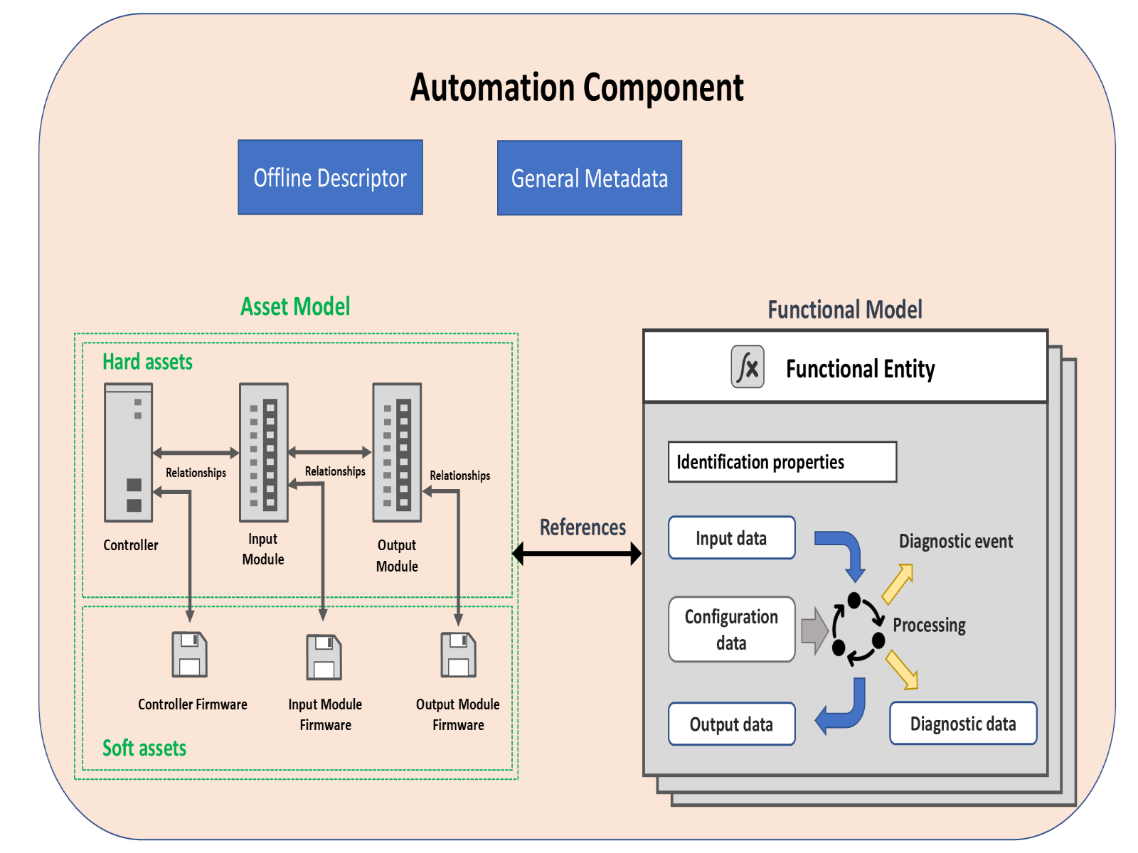
This model is provided to model AutomationComponents in OPC UA FX. In OPC UA FX, an AutomationComponent is an entity that performs one or more automation functions and provides connection capabilities defined in this document. The AutomationComponentType is composed of two major sub-models: the asset model and the functional model. It also provides information related to OfflineEngineering (see OPC 10000-83) and general metadata such as communication capabilities and health status. Figure 1 illustrates this model. For a formal definition of the AutomationComponentType, see 6.2.
Asset information is typically used to describe physical items, but it can also include items that are not physical, such as firmware or licenses. FunctionalEntities encapsulate logical functionality, which can include function blocks, IO module functionality, drive functionality, sensor functionality, actuator functionality, or more complex logical items. FunctionalEntities can be related to Assets, and the representation of such relationships is included in the model. Both Assets and FunctionalEntities can be nested. The Information Model also includes relationships between FunctionalEntities. For a detailed description of the asset model, see the definition of FxAssetType in 6.3. For a detailed description of the FunctionalEntity model, see the definition of FunctionalEntityType in 6.4. For a description of the available ReferenceTypes in this Information Model, see 11.1.
The Information Model is defined to be used either as a base for modelling an AutomationComponentType or for extending an existing Information Model with OPC UA FX-defined functionality. When used as a base model, it is expected that it will require subtyping to add information specific to a component or model, such as variables, or to provide context, e.g., to describe the temperature value in a device that represents a temperature sensor reading. Examples of extending the existing model and using the base model are provided in Annex B.
The AutomationComponentType also includes information related to the offline configuration. For a detailed description of OfflineEngineering, see OPC 10000-83.
4.3 Asset model
4.3.1 Overview
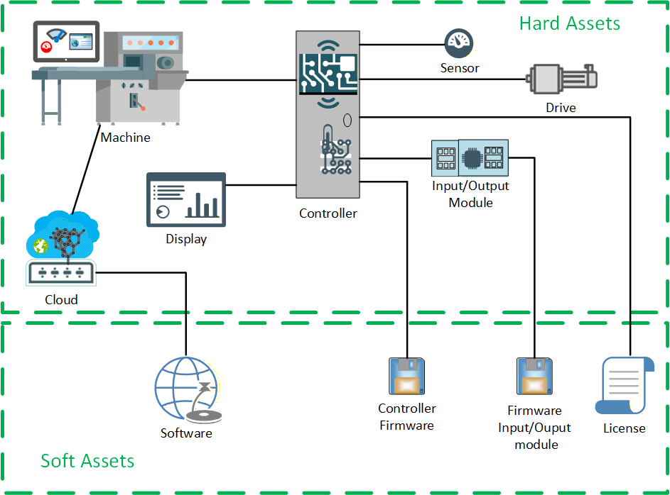
This Information Model provides a general model for Assets in an OPC UA FX system (illustrated in Figure 2). An Asset is defined as a component with a lifecycle, where the lifecycle includes version information. FxAssetType (see 6.3) provides a base concept of the asset model defined in this document. The OPC UA FX Information Model supports the modelling of hard Assets and soft Assets. A hard Asset represents physical hardware like devices, controllers, modules, hardware components, or other hardware-based products. A soft Asset represents firmware, software, licenses, etc. The asset model can model an actual physical device or a virtual representation of the physical device. The asset model is capable of defining a simple Asset, such as a sensor or a complex Asset, such as a machine with multiple nested and/or related Assets.
The asset model is designed to support the nesting of Assets into higher-level devices. The asset model could be used as a base model for plant-wide asset management systems.
4.3.2 Asset information
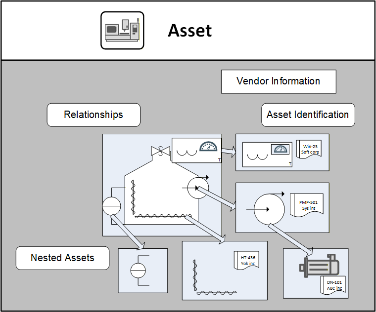
The asset model (illustrated in Figure 3) requires that Assets provide a minimum level of information. This includes Asset type identification as well as the unique identification of Asset instances. It also contains vendor information and information from the model defined in OPC UA Devices (see OPC 10000-100). The asset model supports functionality to verify the identity and compatibility of the Assets. For a complete description of the FxAssetType, see 6.3.
4.3.3 Asset model relationships
The asset model provides a means for representing the relationships between Assets. It also supports the concept that there might be multiple types of relationships between various Assets. These types of relationships might be used to provide multiple views of the asset model. For example:
Asset management view
Physical hierarchy view
Maintenance view
Interconnected view (network, electrical, hydraulic)
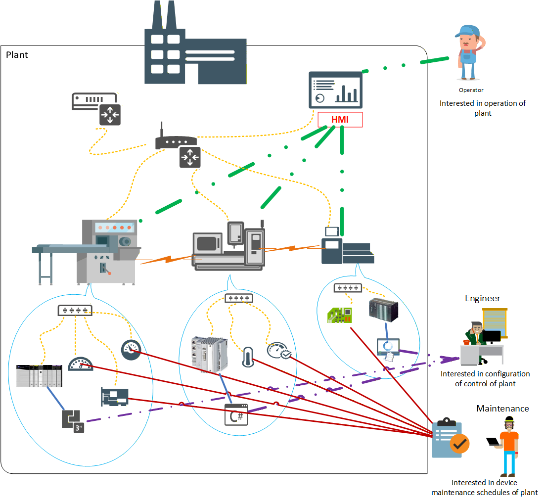
Vendors or end-users are free to create their own view of the Asset relationships. The asset model makes use of specific ReferenceTypes to represent these relationships. OPC 10000-5 and OPC 10000-23 define some base ReferenceTypes, but this document further extends the available list of ReferenceTypes (see 11.1). Figure 4 illustrates some possible views that an asset model can include. Some Assets could contain other Assets (blue speech bubble), while some are just related to each other (orange lightning bolts). There could be network views showing the network topology (yellow dashed lines), which can be derived from LLDP or other input (see OPC 10000-82). There could be a list of sensors or other devices that require routine maintenance (solid red line). There might be a list of all software Assets that an engineer is responsible for (purple dash-dot lines), and the software Asset might be related to the hardware on which it is executed (green dash-dot-dot lines). All of these Assets might be part of a single plant.
The asset model can be as complex or as simple as a specific installation requires. This basic asset model can be part of a plant-wide asset management system or might be a simple asset model used for identity verification. OPC UA FX expects that this model will be extended and that it can operate with other higher-level asset management systems. The asset model might be dynamic during operation.
OPC UA FX defines a minimum asset model that all AutomationComponents are required to support.
4.4 Functional model
4.4.1 Overview
FunctionalEntities encapsulate logical functionality. The OPC UA FX Information Model defines an Object Model for FunctionalEntities. Figure 5 illustrates the Object Model, which includes general information about the FunctionalEntityType, its input variables, output variables, and diagnostic information. FunctionalEntities can be nested or have relationships to other FunctionalEntities. The Object Model also includes a representation of Connections (communication) between FunctionalEntities.
FunctionalEntities are designed to describe the functionality of any complexity, ranging from the acquisition of a single measured value to controlling an entire machine or production line. FunctionalEntities can be preconfigured and fixed, e.g., in a device such as a drive, or they can be dynamically created during engineering or at run time, e.g., in a programmable device such as a controller.
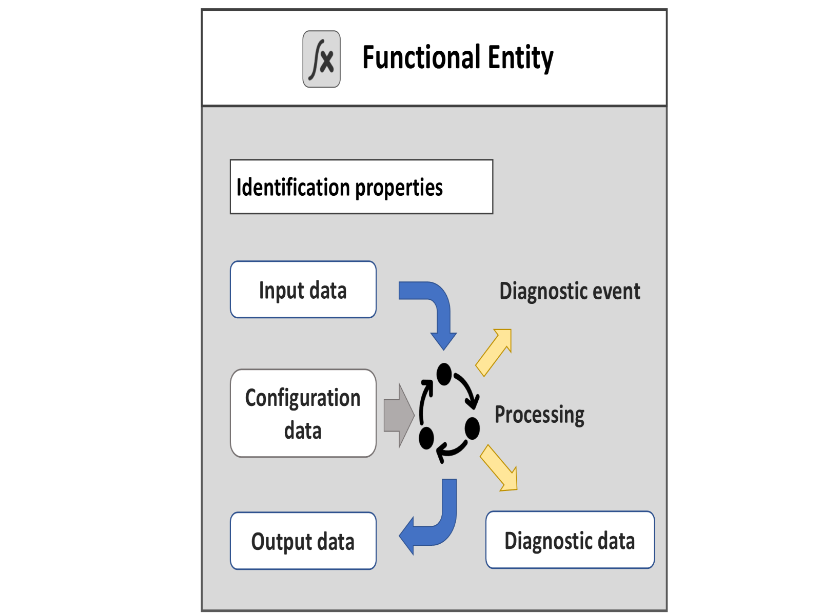
4.4.2 FunctionalEntityType
The FunctionalEntityType defines the base information and functionality that all FunctionalEntities provide. The FunctionalEntityType provides data and methods to control and monitor its functionality. This includes input, output, and configuration data. A FunctionalEntity also provides identification information and methods to perform functionality-related verifications. An important part of the FunctionalEntity model is the interaction between FunctionalEntities, which is modelled as a Connection. The FunctionalEntity part of the model includes information such as status, diagnostics, and other information to help represent this Connection:
Identification properties: Identity – When establishing a Connection between FunctionalEntities, it could be essential to confirm identity, e.g. to check that the other FunctionalEntity is the one that is expected. For an overview of verification, see 5.2.
Input data – describes the values that are produced by another FunctionalEntity and consumed by this FunctionalEntity.
Output data – describes the values that are produced by the processing of this FunctionalEntity and are available for other FunctionalEntities to consume.
Configuration data – describes any value that is used to set up and configure functionality.
Diagnostic data – describes information related to the status of its functionality, including the status of any Connections. This could include the generation of Events or Alarms related to problems or issues encountered by the FunctionalEntity.
4.4.3 FunctionalEntity type hierarchy
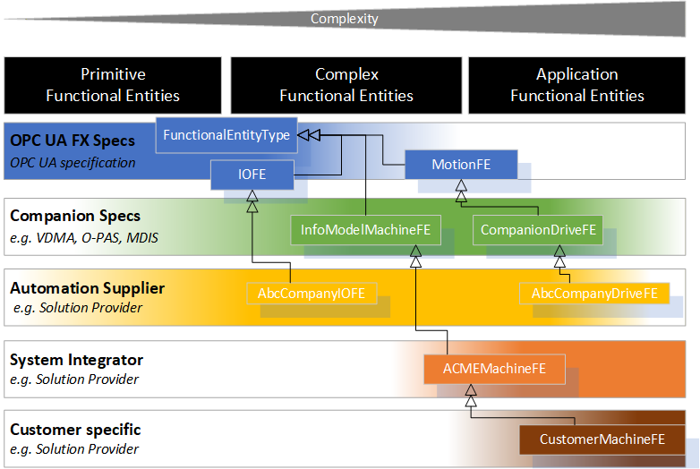
A FunctionalEntity can be of varying degrees of complexity and can represent different granularity and abstraction levels, from primitive functionality to an entire application. Various providers could define FunctionalEntities. For example:
there are primitive FunctionalEntities that only generate output data, like a temperature sensor or only receive input data, like a relay;
more complex FunctionalEntities like a motion axis can receive control data, perform a calculation or action, provide status/feedback data, expose methods for operation and have different operating modes, including closed-loop controls;
or FunctionalEntities on the process application level, representing an entire application, such as a paper machine or a boiler, where the FunctionalEntity has multiple nested SubFunctionalEntities.
This document defines the FunctionalEntityType base type. Various companion standards can provide extensions to this document. Manufacturers or suppliers can provide further extensions to FunctionalEntities. They can group them or structure them into a nested hierarchy. Finally, machine builders or end-users can provide FunctionalEntities for their individual automation solutions (see Figure 6 for examples of possible derivations).
The model is defined using OPC UA Interfaces. An Information Model defined in another standard can add support for FunctionalEntities by including these Interfaces or deriving from the FunctionalEntityType.
4.5 Relationships between FunctionalEntities and Assets
Assets can be related to FunctionalEntities. A single Asset might be related to zero or more FunctionalEntities. A FunctionalEntity might be related to zero or more Assets. The models for both FunctionalEntities and Assets are independent. Specific References only link them (see Figure 7 for an illustration and 11.1 for details on ReferenceTypes).
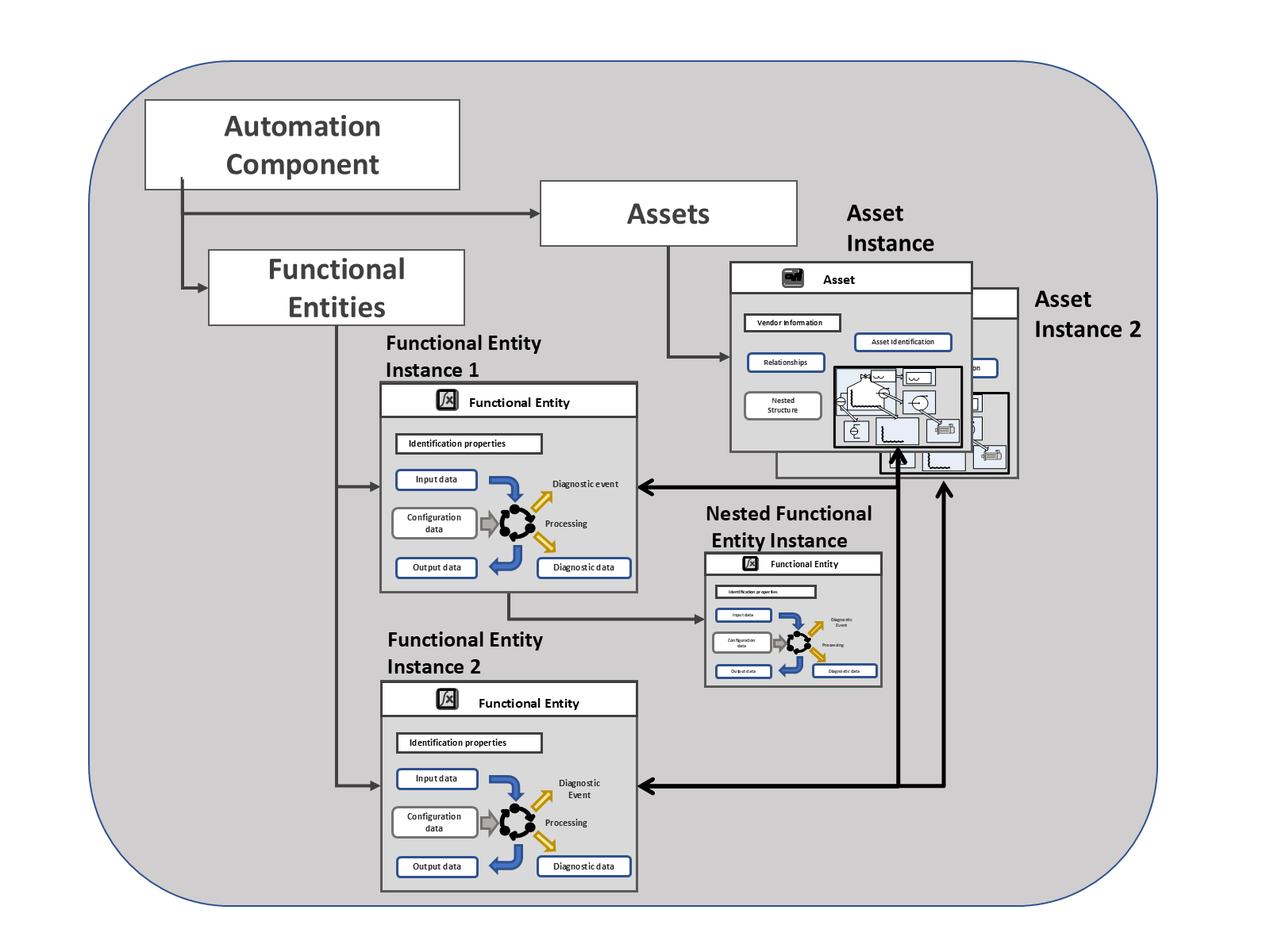
Figure 7 also illustrates an AutomationComponent, which provides a grouping of related FunctionalEntities and Assets.
4.6 FunctionalEntities and applications
Functionality from different FunctionalEntities (in different AutomationComponents) can be used to construct applications. An application can involve communication between one or more FunctionalEntities. FunctionalEntities can be arranged into hierarchies or any type of organisation. The details required in a FunctionalEntity for an application are application-specific, but the base functional model is required to describe the interaction between the FunctionalEntities so that all interactions can be represented in the same manner.
A FunctionalEntity can interact with other FunctionalEntities by exchanging data. This exchange of data can be for control or monitoring purposes. Information related to these interactions is represented in the FunctionalEntity by Connections (see Figure 8).
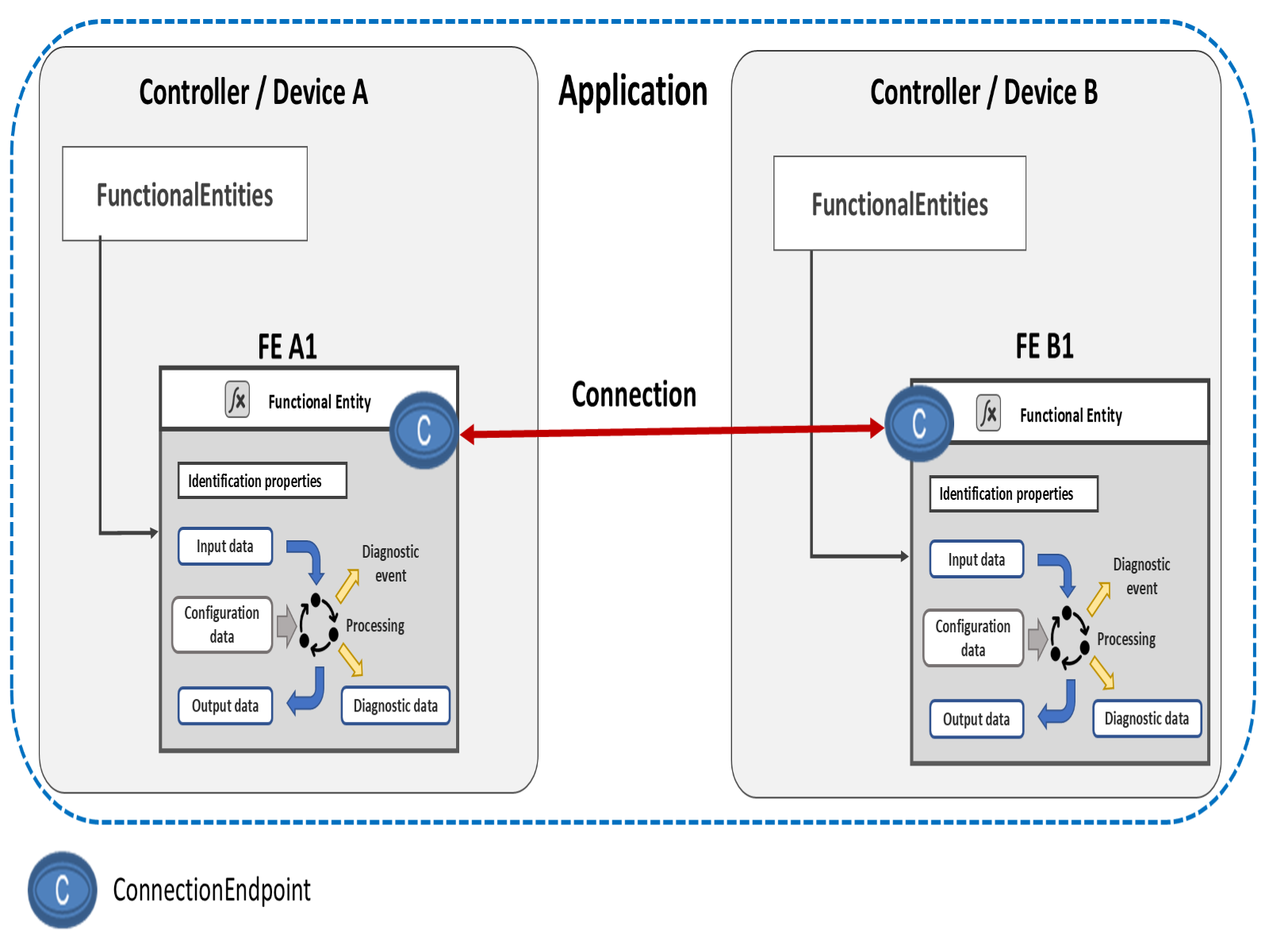
The process of establishing a Connection can include identity and compatibility verification, identifying the information to be exchanged, establishing exclusive access (locking) to the information, setting ConfigurationData, configuring the communication, and finally, enabling the communication. An established Connection is represented on a connected FunctionalEntity by the ConnectionEndpoint. For more information, see the definition of the ConnectionEndpointType in 6.6.
The FunctionalEntity can group input data and output data for easier configuration or as the application requires.
A FunctionalEntity exposes ControlGroups to allow the selection between available uses of a FunctionalEntity. The selected use might restrict access to data; it might lock a value from being changed or only to be changed by a specific entity or Role. Multiple ControlGroups might reference overlapping data. ControlGroups might be created dynamically or be pre-configured as part of an application. ControlGroups might be nested. For more information, see the definition of the ControlGroupType in 6.5. ControlGroups use a Controls Reference defined in OPC 10000-23 to indicate who owns the ControlGroup.
Transportation of data between FunctionalEntities can be accomplished using existing OPC UA communication models. The FunctionalEntity includes Connection information that reflects the established communication model, represented by ConnectionEndpoints. For more information, see 6.6.
4.7 ConnectionManager
4.7.1 Overview
A ConnectionManager is an optional entity that interacts with multiple AutomationComponents to establish Connections between FunctionalEntities. The ConnectionManager can execute on any Server supporting the OPC UA FX Information Model. In the OPC UA FX Information Model, the ConnectionManager is represented by the ConnectionManagerType, which defines functionality and interfaces to manage the establishment of Connections between FunctionalEntities.
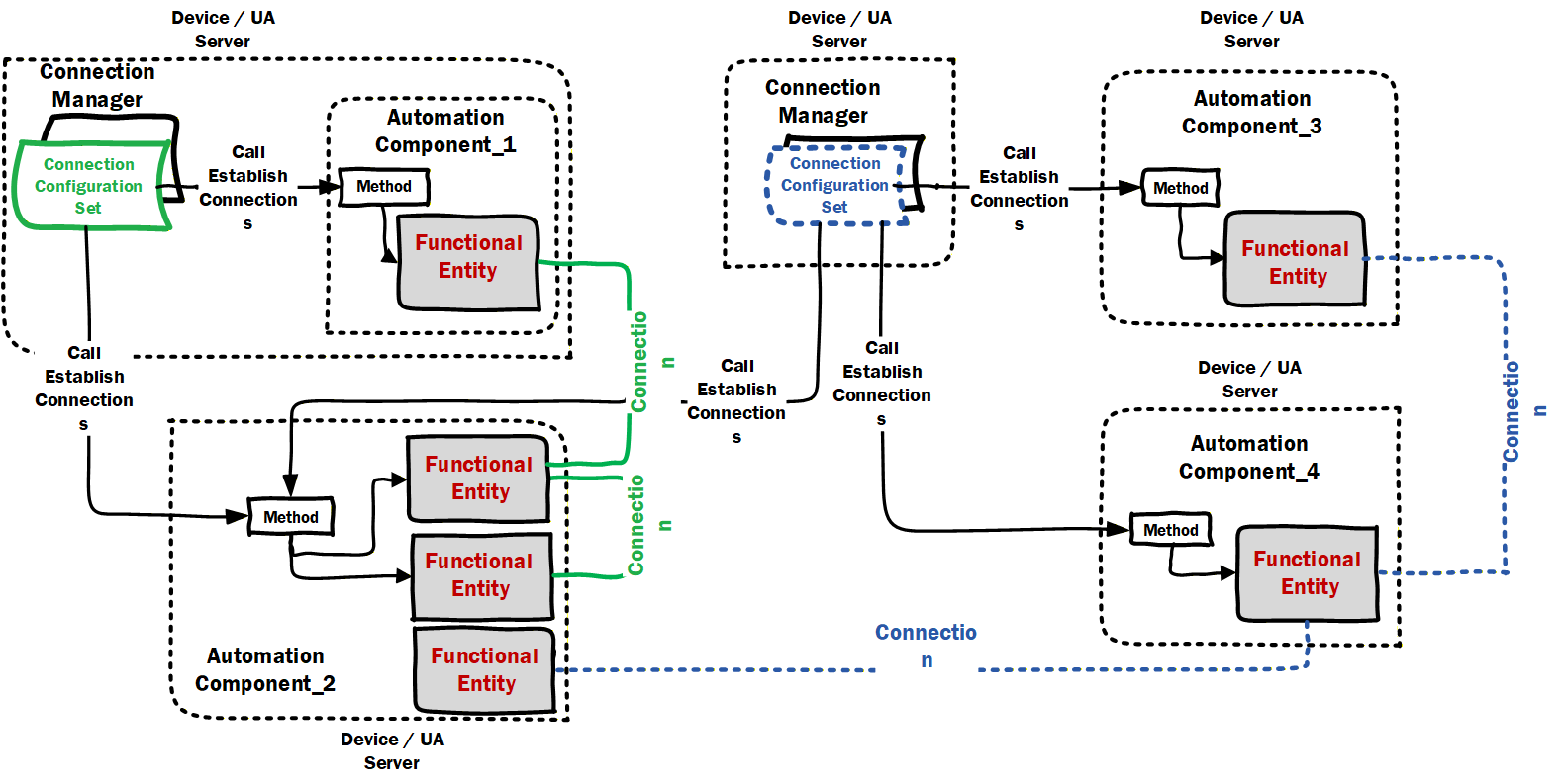
Several ConnectionManagers within a network could establish Connections independently of each other. For example, a ConnectionManager on a controller can establish Connections from the controller to its associated IO devices. In contrast, another ConnectionManager on a line controller could establish Connections between FunctionalEntities on the controllers. Figure 9 illustrates possible deployments of a ConnectionManager. It also illustrates ConnectionConfigurationSets, which contain the information needed to establish Connections.
For a conceptual overview of how Connections are established by a ConnectionManager and the main ObjectTypes used in this process, see 5.5.
This document defines the core functionality of a ConnectionManager with respect to the process of establishing and closing Connections, reporting errors related to it, and the ConnectionConfigurationSets. This document does not define the implementation of a ConnectionManager. It can be implemented as a standalone application that monitors and manages Connections. It can be integrated into a vendor application, which establishes and closes Connections according to the overall application. The vendor application can also monitor the state of established Connections and trigger a re-establishment of Connections.
NOTE For simplicity in this document, we will describe that a ConnectionManager monitors a Connection, with it being understood that this could be some other application.
4.7.2 Creating / Monitoring / Closing Connections
Connections to be created are part of a ConnectionManager configuration (ConnectionConfigurationSet).
An AutomationComponent and the included FunctionalEntities report the status of Connections that are part of the FunctionalEntity, and Clients can monitor this status. Some ConnectionManagers could provide the following:
know when to create a Connection,
respond to an application that knows when to create a Connection.
respond to external or internal commands.
monitor the Connections they create.
Possible reasons for monitoring Connection status include:
An application or ConnectionManager monitors ConnectionEndpoints on AutomationComponents to decide whether it needs to (re)establish or close Connections. For example:
On startup, it checks if the desired Connections already exist. For Connections that do not exist, it could trigger the establishment processing.
At runtime, it would check if any Connections were cleaned up (see 5.5.4) or disappeared (e.g. restarted application). If so, it could trigger establishment processing on the Connection.
It might determine, for application-defined reasons, that a Connection needs to be closed, and it could trigger the close Connection processing.
Vendor-specific diagnostic applications monitor Connections defined in ConnectionConfigurationSets on a ConnectionManager and the ConnectionEndpoints on AutomationComponents to present comprehensive Connection information to the operator or engineers, including identification information, current status and last error information.
ConnectionManagers can expose capabilities that describe the functionality they provide (see 6.7.2).