FunctionalEntities encapsulate logical functionality. The OPC UA FX Information Model defines an Object Model for FunctionalEntities. Figure 5 illustrates the Object Model, which includes general information about the FunctionalEntityType, its input variables, output variables, and diagnostic information. FunctionalEntities can be nested or have relationships to other FunctionalEntities. The Object Model also includes a representation of Connections (communication) between FunctionalEntities.
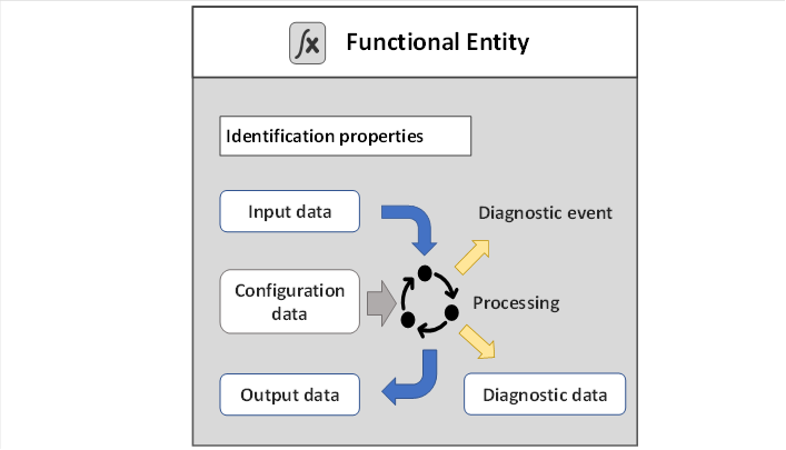
Figure 5 – FunctionalEntity illustration
FunctionalEntities are designed to describe the functionality of any complexity ranging from an acquisition of a single measured value to controlling an entire machine or production line. FunctionalEntities can be preconfigured and fixed, e.g., in a device such as a drive, or they can be dynamically created during engineering or at run time, e.g., in a programmable device such as a controller.
The FunctionalEntityType defines the base information and functionality that all FunctionalEntities provide. The FunctionalEntityType provides data and methods to control and monitor its functionality. This includes input, output, and configuration data. A FunctionalEntity also provides identification information and methods to perform functionality-related verifications. An important part of the FunctionalEntity model is the interaction between FunctionalEntities, which is modelled as a Connection. The FunctionalEntity part of the model includes information such as status, diagnostics, and other information to help represent this Connection:
- Identification properties: Identity – When establishing a Connection between FunctionalEntities, it may be essential to confirm identity, meaning to check that the other FunctionalEntity is the one that is expected. For an overview of verification, see 5.2.
- Input data – describes the values that may be produced by another FunctionalEntity and consumed by this FunctionalEntity.
- Output data – describes the values that are produced by the processing of this FunctionalEntity and are available for other FunctionalEntities to consume.
- Configuration data – describes any value that is used to set up and configure functionality.
- Diagnostic data – describes information related to the status of its functionality, including the status of any Connections. This may include the generation of Events or Alarms related to problems or issues encountered by the FunctionalEntity.
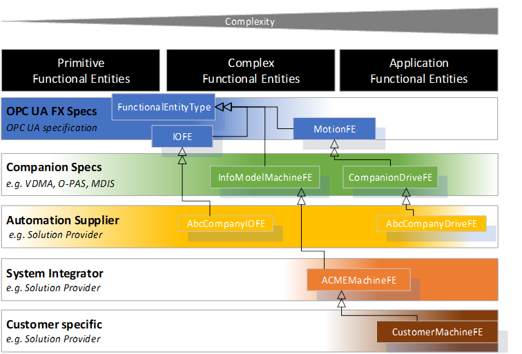
A FunctionalEntity can be of varying degrees of complexity and can represent different granularity and abstraction levels, from primitive functionality to an entire application. Various providers could define FunctionalEntities. For example:
- there are primitive FunctionalEntities that only generate output data like a temperature sensor or only receive input data like a relay;
- more complex FunctionalEntities like a motion axis can receive control data, perform a calculation or action, provide status/feedback data, expose methods for operation and have different operating modes, including closed-loop controls;
- or FunctionalEntities on the process application level representing an entire application, such as a paper machine or a boiler, where the FunctionalEntity has multiple nested SubFunctionalEntities.
This document defines the FunctionalEntityType base type. Various companion standards may provide extensions to this document. Manufacturers or suppliers may provide further extensions to FunctionalEntities. They may group them or structure them into a nested hierarchy. Finally, machine builders or end-users may provide FunctionalEntities for their individual automation solutions (see Figure 6 for examples of possible derivations).
The model is defined using OPC UA Interfaces. An Information Model defined in another standard can add support for FunctionalEntities by including these Interfaces or deriving from the FunctionalEntityType.