This chapter describes in detail the protocol that is used for the safety communication layer.
Figure 11 shows the structure of a RequestSPDU which originates at the SafetyConsumer and contains a SafetyConsumerID, a MonitoringNumber (MNR), and one octet of (non-safety-related) Flags. See 7.2.1.2 to 7.2.1.4 for details. See 6.2.3.3 for details on the RequestSPDUDataType definition.
NOTE 1 The RequestSPDU does not contain a CRC signature.
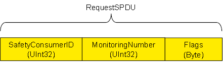
Figure 12 shows the structure of a ResponseSPDU which originates at the SafetyProvider and contains the SafetyData (1 to 1 500 octets), an additional 25 octet safety code (STrailer) and the NonSafetyData. See 7.2.1.5 to 7.2.1.11 for details. See 6.2.3.4 for details on the ResponseSPDUDataType definition.
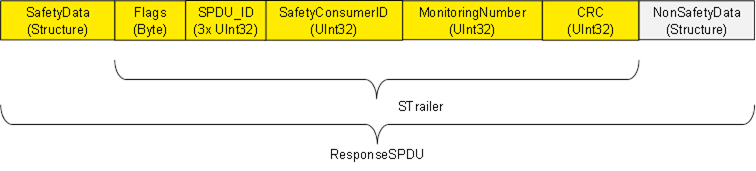
NOTE 2 To avoid spurious trips, the ResponseSPDU is transmitted in an atomic (consistent) way from the OPC UA Platform Interface of the SafetyProvider to the OPC UA Platform Interface of the SafetyConsumer. This is the task of the respective OPC UA mapper, see Figure 2.
Identifier of the SafetyConsumer instance, for diagnostic purposes, see 9.1.2.
The SafetyConsumer uses the MNR to detect SPDUs with timeliness errors, e.g. such SPDUs which are continuously repeated by an erroneous network element which stores data. A different MNR is used in every RequestSPDU of a given SafetyConsumer, and a ResponseSPDU will only be accepted if its MNR matches the MNR of the corresponding RequestSPDU.
The checking for correctness of the MNR is only performed by the SafetyConsumer.
[RQ7.1] The flags of the SafetyConsumer (RequestSPDU.Flags) shall be used as shown in 6.2.3.1.
[RQ7.2] SafetyData shall contain the safety-related application data transmitted from the SafetyProvider to the SafetyConsumer. It is comprised of a single or multiple basic OPC UA Variables (see 6.2.5). For the sake of reducing distinctions of cases, SafetyData shall always be a Structure, even if it comprised of only a single basic OPC UA Variable.
For the calculation of the CRC signature, the order in which this data is processed by the calculation is important. SafetyProvider and SafetyConsumer shall agree upon the number, type and order of application data transmitted in SafetyData. The sequence of SafetyData is fixed.
SafetyData may contain qualifiers for a fine-grained activation of fail-safe substitute values. For valid process values, the respective qualifiers are set to 1 (good), whereas the value 0 (bad) is used for invalid values. Invalid process values are replaced by fail-safe substitute values in the SafetyConsumer’s safety application. See 6.3.6.
[RQ7.3] The flags of the SafetyProvider (ResponseSPDU.Flags) shall be used as shown in 6.2.3.2.
[RQ7.4] Flags in the ResponseSPDU.Flags which are reserved for future use shall be set to zero by the SafetyProvider and shall not be evaluated by the SafetyConsumer.
This field is used by the SafetyConsumer to check whether the ResponseSPDU is coming from the correct SafetyProvider. For details, see 7.2.3.1.
[RQ7.5] The SafetyConsumerID in the ResponseSPDU shall be a copy of the SafetyConsumerID received in the corresponding RequestSPDU. See 7.2.3.1.
[RQ7.6] The MonitoringNumber in the ResponseSPDU shall be a copy of the MonitoringNumber received in the corresponding RequestSPDU. See 7.2.3.1.
NOTE The SafetyConsumer uses the ResponseSPDU.MonitoringNumber to detect SPDUs received with timeliness error, e.g. SPDUs which are continuously repeated by an erroneous network element which stores data. A different MonitoringNumber is used in every RequestSPDU of a given SafetyConsumer, and a ResponseSPDU will only be accepted if its MonitoringNumber matches the MonitoringNumber in the corresponding RequestSPDU.
[RQ7.7] The ResponseSPDU CRC shall be used to detect data corruption. See 7.2.3.6 on how it is calculated in the SafetyProvider and how it is checked in the SafetyConsumer.
[RQ7.8] This structure shall be used to transmit NonSafetyData values (e.g. diagnostic information) together with SafetyData consistently. NonSafetyData is not CRC-protected and can stem from an unsafe source.
[RQ7.9] When presented to the safety application (e.g. at an output of the SafetyConsumer), non-safety values shall clearly be indicated as “non-safety” by an appropriate vendor-specific mechanism (e.g. by using a different colour).
To avoid possible problems with empty structures, the dummy structure NonSafetyDataPlaceholder shall be used when no NonSafetyData is used (see requirement RQ6.8).
The two SCL services SafetyProvider and SafetyConsumer are specified using state diagrams.
Figure 13 and Figure 14 show sequences of requests and responses with SafetyData for this document using OPC UA Client/Server and PubSub communication mechanisms, respectively. The figures show selected scenarios only and are therefore informative.
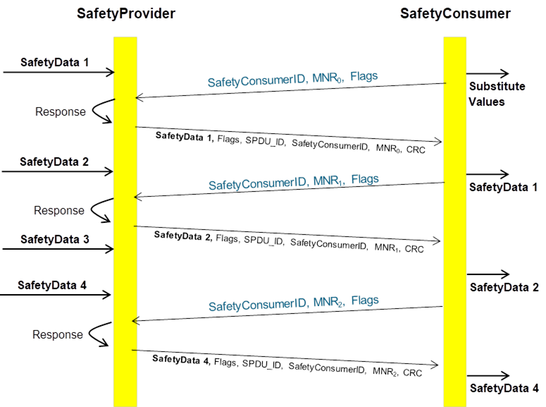
Figure 13 (informative) – Sequence diagram for requests and responses (Client/Server)
[RQ7.10] In the case of Client/Server communication, a SafetyConsumer’s OPC UA Mapper may call a SafetyProvider (either the state machine implementation itself or the SafetyProvider’s OPC UA Mapper) with an identical RequestSPDU multiple times in a row. In that case, the SafetyProvider (state machine or OPC UA Mapper) shall answer all requests. The returned ResponseSPDUs may contain different values (e.g. currently available process values) or contain the initially returned values.
[RQ7.11] For each SafetyProvider, the implemented choice of behaviour according to RQ7.10 (i.e. whether currently available process values or initially returned values will be used) shall be documented in the corresponding safety manual.
NOTE 2 Since a SafetyConsumer checks for changed MNRs in ResponseSPDUs (see SafetyConsumer state S14_WaitForChangedSPDU in Table 34 and transition T17 in Table 35), and therefore will use only the first evaluated ResponseSPDU for a given MNR and all further ResponseSPDUs with the same MNR will be ignored.
NOTE The bold arrows represent communication with new data values, whereas dashed arrows contain repeated data values.
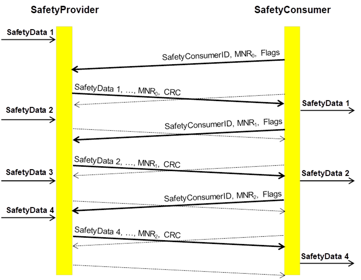
Figure 14 (informative) – Sequence diagram for requests and responses (PubSub)
NOTE 3 The state machines according to this document do not contain any retry-mechanisms to increase fault tolerance. In contrast, it is assumed that retry is already handled within the OPC UA stack (e.g. when using Client/Server, or by choosing a higher update rate for PubSub). The dashed lines therefore are not part of this document, but rather symbolize the repeated sending of data implemented in the OPC UA stack.
The SafetyConsumerTimeout is the watchdog time checked in the SafetyConsumer. The watchdog is restarted immediately before a new RequestSPDU is generated (transitions T14 and T28 of the SafetyConsumer in Table 35). If an appropriate ResponseSPDU is received in time, and the checks for data integrity, authenticity, and timeliness are all valid, the timer will not expire before it is restarted.
Otherwise, the watchdog timer expires, and the SafetyConsumer triggers a safe reaction. To duly check its timer, the SafetyConsumer is executed cyclically, with period ConsumerCycleTime. ConsumerCycleTime is expected to be smaller than SafetyConsumerTimeout.
The ConsumerCycleTime is the maximum time for the cyclic update of the SafetyConsumer. It is the timeframe from one execution of the SafetyConsumer to the next execution of the SafetyConsumer. The implementation of the monitoring of the ConsumerCycleTime and the reaction in case of exceeding the ConsumerCycleTime are not part of this document; these are vendor-specific.
[RQ7.12] The ConsumerCycleTime shall be monitored in a safety-related way.
[RQ7.26] A change of the SafetyConsumerTimeout parameter value shall take immediate effect on the ConsumerTimer.
In case it is necessary to ensure that a given SafetyData (e.g. a safety demand or a command value) that originates in the SafetyProvider’s safety application is being received by a SafetyConsumer and forwarded to the SafetyConsumer’s safety application, i.e. if no SafetyData in a series of SafetyData is to be missed, the following two cases shall be considered.
In case A, repeated identical RequestSPDUs are being answered by the SafetyProvider with ResponseSPDUs which contain the initially returned value. This is the case for PubSub communication and is a choice for Client/Server communication, see RQ7.11. In this case, the SafetyProvider’s safety application shall provide the respective SafetyData at the SafetyProvider’s SAPI until at least one change of the MNR is detected.
In case B, repeated identical RequestSPDUs are being answered by the SafetyProvider with the currently available SafetyData. This is a choice for Client/Server communication, see RQ7.11. In this case, the SafetyProvider’s safety application shall provide the respective SafetyData at the SafetyProvider’s SAPI until at least two changes of the MNR have been detected.
Figure 15 and Figure 16 show examples justifying case B by depicting two sequences of ResponseSPDUs as sent by a SafetyProvider. Due to the cycles of SafetyProvider and SafetyConsumer not being synchronized, a SafetyConsumer can evaluate any one of a given number of ResponseSPDUs for a given RequestSPDU.
In the examples, the SafetyData is made up of two components: the “respective safety data”, i.e. a safety demand that is not to be missed (one of the values “A”, “B” or “C”) and non-demand numerical measurement values for which it does not matter whether some are not received by the SafetyConsumer.
The worst-case time to make sure that the respective safety data from the SafetyProvider is made available to the SafetyConsumer is two times the SafetyConsumerTimeout. This worst-case time occurs when the two transmissions of a RequestSPDU and its corresponding ResponseSPDU, which are necessary according to the descriptions above, each take a time of just slightly under one SafetyConsumerTimeout.
If the SafetyConsumer’s SafetyConsumerTimeout is known at the SafetyProvider, the SafetyProvider may alternatively provide the respective safety data for at least two times the SafetyConsumerTimeout to ensure that the respective safety data reaches the SafetyConsumer.
Since NonSafetyData is consistently transmitted with SafetyData, the same considerations apply for NonSafetyData.
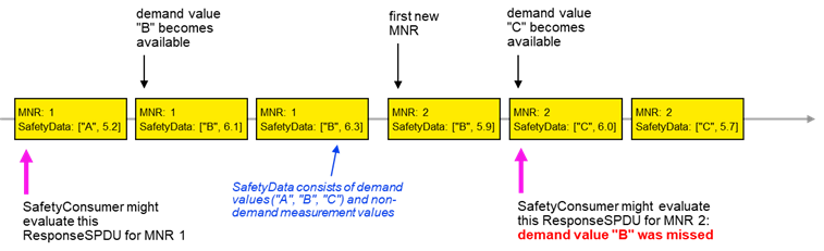
Figure 15 – Duration of demand example for missed demand value in case of currently available SafetyData not being provided until second change of MNR
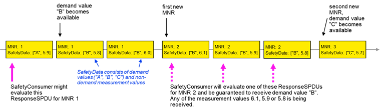
Figure 16 – Duration of demand example for received demand value in case of currently available SafetyData being provided
[RQ7.13] Figure 17 shows a simplified representation of the state diagram of the SafetyProvider. The exact behaviour is described in Table 30, Table 31, and Table 32. The SafetyProvider shall implement that behaviour. It is not required to literally follow the entries given in the tables, if the externally observable behaviour does not change.
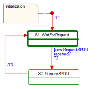
Figure 17 – Simplified representation of the state diagram for the SafetyProvider
Table 29 shows the symbols used for state machines.
Table 29 – Symbols used for state machines
|
Graphical representation |
Type |
Description |
|
|
Activity state |
Within these interruptible activity states the SafetyProvider waits for new input. |
|
|
Action state |
Within these non-interruptible action states events like new requests are deferred until the next activity state is reached, see [1]. |


The transitions are fired in case of an event. “Event” in this context means either a Method call in the case of Client/Server communication or the detection of a changed RequestSPDU by the OPC UA Mapper in the case of PubSub communication.
In case of several possible transitions, so-called guard conditions (refer to […] in UML diagrams) define which transition to fire.
The diagram consists of activity and action states. Activity states are surrounded by bold lines, action states are surrounded by thin lines. While activity states can be interruptible by new events, action states are not. External events occurring while the state machine is in an action state, are deferred until the next activity state is reached.
NOTE The details on how to implement activity states and action states are vendor-specific. Typically, in a real-time system the task performing the SafetyProvider or SafetyConsumer state machine is executed cyclically (see 6.3.5). Whenever the task is woken up by the scheduler of the operating system while it is in an action state, it executes action states until its time slice is used up, or an activity state is reached. Whenever a task being in an activity state is woken up, it checks for input. If no new input is available, it immediately returns to the sleep state without changing state.
If input is available, it starts executing action states until its time-slice is up or until the next activity state is reached.
Table 30 shows the internal items of a SafetyProvider instance.
Table 30 – SafetyProvider instance internal items
|
Internal items |
Type |
Definition |
|
RequestSPDU_i |
Variable |
Local memory for RequestSPDU (required to react on changes). |
|
SPDU_ID_1_i |
UInt32 |
Local variable to store SPDU_ID_1. |
|
SPDU_ID_2_i |
UInt32 |
Local variable to store SPDU_ID_2. |
|
SPDU_ID_3_i |
UInt32 |
Local variable to store SPDU_ID_3. |
|
BaseID_i |
Guid |
Local variable containing the BaseID (taken either from the SPI or SAPI). |
|
ProviderID_i |
UInt32 |
Local variable containing the ProviderID (taken either from the SPI or SAPI). |
|
<Get RequestSPDU> |
Macro |
Instruction to take the whole RequestSPDU from the OPC UA Mapper. |
|
<Set ResponseSPDU> |
Macro |
Instruction to transfer the whole ResponseSPDU to the OPC UA Mapper. |
|
<Calc SPDU_ID_i> |
Macro |
const uint32 SafetyProviderLevel_ID:= … // see 7.2.3.4 If(SAPI.SafetyBaseID == 0) thenBaseID_i:= SPI.SafetyBaseIDConfiguredElseBaseID_i:= SAPI.SafetyBaseID EndifIf(SAPI.SafetyProviderID == 0) thenProviderID_i:= SPI.SafetyProviderIDConfiguredElseProviderID_i:= SAPI.SafetyProviderID Endif SPDU_ID_1_i:= BaseID_i (octets 0…3) XOR SafetyProviderLevel_ID SPDU_ID_2_i:= BaseID_i (octets 4…7) XOR SPI.SafetyStructureSignature SPDU_ID_3_i:= BaseID_i (octets 8…11) XOR BaseID_i (octets 12…15) XOR ProviderID_i // see 7.2.3.2 for clarification |
|
<build ResponseSPDU> |
Macro |
Take the MNR and the SafetyConsumerID of the received RequestSPDU. Add the SPDU_ID_1_i, SPDU_ID_2_i, SPDU_ID_3_i, Flags, the SafetyData and the NonSafetyData, as well as the calculated CRC. See 7.2.3.1 |
Table 31 shows the states of a SafetyProvider instance. The SafetyProvider does not check for correct configuration. It will reply to requests even if it is incorrectly configured (e.g. its SafetyProviderID is zero). However, SafetyConsumers will never try to communicate with SafetyProviders having incorrect parameters, see Transitions T13 and T27 in Table 35 and the macro <ParametersOK?> in Table 33.
Table 31 – States of SafetyProvider instance
|
State name |
State description |
|
Initialization |
// Initial state SAPI.SafetyData:= 0 SAPI.NonSafetyData:= 0SAPI.MonitoringNumber:= 0SAPI.SafetyConsumerID:= 0 SAPI.OperatorAckRequested:= 0 RequestSPDU_i:= 0 |
|
S1_WaitForRequest |
// waiting on next RequestSPDU from SafetyConsumer <Get RequestSPDU> |
|
S2_PrepareSPDU |
ResponseSPDU.Flags.ActivateFSV:= SAPI.ActivateFSVResponseSPDU.Flags.OperatorAckProvider:= SAPI.OperatorAckProvider ResponseSPDU.Flags.TestModeActivated:= SAPI.EnableTestMode <Calc SPDU_ID_i> <build ResponseSPDU> // see 7.2.3.1 |
Table 32 shows the transitions of the SafetyProvider.
Table 32 – SafetyProvider transitions
|
Transition |
Source state |
Target state |
Guard condition |
Activity |
|
T1 |
Init |
S1 |
|
|
|
T2 |
S1 |
S2 |
// RequestSPDU received1 - |
// Process request RequestSPDU_i:= RequestSPDU SAPI.MonitoringNumber:= RequestSPDU.MonitoringNumber SAPI.SafetyConsumerID:= RequestSPDU.SafetyConsumerID SAPI.OperatorAckRequested:= RequestSPDU.Flags.OperatorAckRequested |
|
T3 |
S2 |
S1 |
// SPDU is prepared - |
<Set ResponseSPDU> |
|
1 See the preceding explanation in 7.2.2.4 of what constitutes events which trigger this transition. |
||||
[RQ7.14] Figure 18 shows a simplified representation of the state diagram of the SafetyConsumer. The exact behaviour is described in Table 33, Table 34, and Table 35. The SafetyConsumer shall implement this behaviour. It is not required to literally follow the entries given in the tables, if the externally observable behaviour does not change.
To avoid unnecessary spurious trips requiring operator acknowledgment, it is recommended that a SafetyConsumer is started after an OPC UA connection to a running SafetyProvider has been established, or that the setting of input SAPI.Enable to “1” is delayed until the SafetyProvider is running.
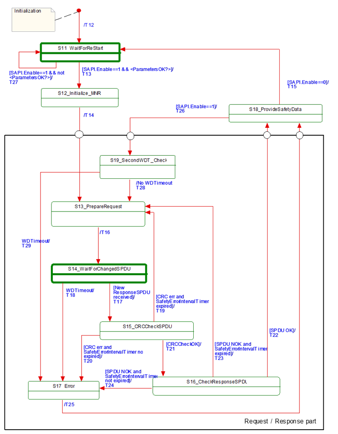
Figure 18 – Principle state diagram for SafetyConsumer
Table 33 shows the internal items of a SafetyConsumer. A macro is a shorthand representation for operations described in the according definition.
Table 33 – SafetyConsumer internal items
|
Internal items |
Type |
Definition |
|
|
Constants |
|
|
|
|
MNR_min:= 0x100 |
UInt32 |
// 0x100 is the start value for MNR, also used after wrap-around // The values 0…0xFF are reserved for future use |
|
|
Variables |
|
|
|
|
FaultReqOA_i |
Boolean |
Local memory for errors which request operator acknowledgment |
|
|
OperatorAckConsumerAllowed_i |
Boolean |
Auxiliary flag indicating that operator acknowledgment is allowed. It is true if the input SAPI.OperatorAckConsumer has been ‘false’ since FaultReqOA_i was set |
|
|
MNR_i |
UInt32 |
Local MonitoringNumber (MNR) |
|
|
prevMNR_i |
UInt32 |
Local memory for previous MNR |
|
|
ConsumerID_i |
UInt32 |
Local memory for SafetyConsumerID in use |
|
|
CRCCheck_i |
Boolean |
Local variable used to store the result of the CRC check |
|
|
SPDUCheck_i |
Boolean |
Local variable used to store the result of the additional SPDU checks |
|
|
SPDU_ID_1_i |
UInt32 |
Local variable to store the expected SPDU_ID_1 |
|
|
SPDU_ID_2_i |
UInt32 |
Local variable to store the expected SPDU_ID_2 |
|
|
SPDU_ID_3_i |
UInt32 |
Local variable to store the expected SPDU_ID_3 |
|
|
SPI_SafetyConsumerID_i |
UInt32 |
Local variable to store the parameter SafetyConsumerID |
|
|
SPI_SafetyProviderID_i |
UInt32 |
Local variable to store the parameter SafetyProviderID |
|
|
SPI_SafetyBaseID_i |
UInt128 |
Local variable to store the parameter SafetyBaseID |
|
|
SPI_SafetyStructureSignature_i |
UInt32 |
Local variable to store the parameter SafetyStructureSignature |
|
|
SPI_SafetyOperatorAckNecessary_i |
Boolean |
Local variable to store the parameter SafetyOperatorAckNecessary |
|
|
SPI_SafetyErrorIntervalLimit_i |
UInt16 |
Local variable to store the parameter SafetyErrorIntervalLimit |
|
|
MNR_re_sync_i |
Boolean |
Local variable used to support re-synchronization of MNR after detected error |
|
|
Timers |
|
|
|
|
ConsumerTimer |
Timer |
This timer is used to check whether the next valid ResponseSPDU has arrived on time. It is initialized using the parameter SPI.SafetyConsumerTimeout. NOTE As opposed to other parameters, a modification of the parameter value SafetyConsumerTimeout takes effect immediately, i.e. not only when state S11 is visited, see RQ7.26. |
|
|
ErrorIntervalTimer |
Timer |
This timer is used to check the elapsed time between errors. If the elapsed time between two consecutive errors is smaller than the value SafetyErrorIntervalLimit, FSV will be activated. Otherwise, the ResponseSPDU is discarded and the SafetyConsumer waits for the next ResponseSPDU. This timer is initialized using the local variable SPI_SafetyErrorIntervalLimit_i. See Table 26, 6.3.4.3, and 9.4 for more information. NOTE The local variable SPI_SafetyErrorIntervalLimit_i is not to be confused with the parameter SPI.SafetyErrorIntervalLimit. The local variable is copied from the parameter in state S11 (restart). Hence, if the parameter value changes during runtime, the new value will only be used after the connection has been restarted. |
|
|
Macros <...><...> |
|
|
|
|
<risingEdge x> |
Macro |
// detection of a rising edge: If x==true && tmp==false Then result:= trueElse result:= falseEndif tmp:= x |
|
|
<Get ResponseSPDU> |
Macro |
Instruction to take the whole ResponseSPDU from the OPC UA Mapper. |
|
|
<Use FSV> |
Macro |
SAPI.SafetyData is set to binary 0 If [<ConsumerTimer expired || SAPI.Enable==0 ?>]ThenSAPI.NonSafetyData is set to binary 0 ElseSAPI.NonSafetyData is set to ResponseSPDU.NonSafetyData Endif SAPI.FSV_Activated:= 1 RequestSPDU.Flags.FSV_Activated:= 1 NOTE 1 If a safety application prefers fail-safe values other than binary 0, this can be implemented in the safety application by querying SAPI.FSV_Activated. NOTE 2 The NonSafetyData is always updated if data is available. In case of a timeout, no data is available, which is indicated using binary zero. If it is necessary for an application to distinguish between “no data available” and “binary zero received”, it can add a Boolean variable to the NonSafetyData. This value is set to ”1” during normal operation, and to ”0” for indicating that no data is available. |
|
|
<Use PV> |
Macro |
SAPI.SafetyData is set to ResponseSPDU.SafetyData SAPI.NonSafetyData is set to ResponseSPDU.NonSafetyData SAPI.FSV_Activated:= 0 RequestSPDU.Flags.FSV_Activated:= 0 RequestSPDU.Flags.CommunicationError:= 0 |
|
|
<Set RequestSPDU> |
Macro |
Instruction to transfer the whole RequestSPDU to the OPC UA Mapper. |
|
|
<(Re)Start ConsumerTimer> |
Macro |
Restarts the ConsumerTimer. |
|
|
<(Re)Start ErrorIntervalTimer> |
Macro |
Restarts the ErrorIntervalTimer. |
|
|
<ConsumerTimer expired?> |
Macro |
Yields “true” if the timer is running longer than SPI.SafetyConsumerTimeout since last restart, “false” otherwise. |
|
|
<ErrorIntervalTimer expired?> |
Macro |
Yields “true” if the timer is running longer than SPI.SafetyErrorIntervalLimit since last restart, “false” otherwise. |
|
|
<Assign ConsumerID> |
Macro |
If SAPI.SafetyConsumerID != 0 Then ConsumerID_i:= SAPI.SafetyConsumerID Else ConsumerID_i:= SPI_SafetyConsumerID_i EndifRequestSPDU.SafetyConsumerID:= ConsumerID_i |
|
|
<Calc SPDU_ID_i> |
Macro |
uint128 BaseID uint32 ProviderID const uint32 SafetyProviderLevel_ID:= … // see 7.2.3.4 If(SAPI.SafetyBaseID == 0) ThenBaseID:= SPI_SafetyBaseID_iElseBaseID:= SAPI.SafetyBaseID EndifIf(SAPI.SafetyProviderID == 0) ThenProviderID:= SPI_SafetyProviderID_iElseProviderID:= SAPI.SafetyProviderID Endif SPDU_ID_1_i:= BaseID (octets 0…3) XOR SafetyProviderLevel_ID SPDU_ID_2_i:= BaseID (octets 4…7) XOR SPI_SafetyStructureSignature_i SPDU_ID_3_i:= BaseID (octets 8…11) XOR BaseID (octets 12…15) XOR ProviderID // see 7.2.3.2 for clarification |
|
|
<ParametersOK?> |
Macro |
Boolean result:= trueIf(SAPI.SafetyBaseID == 0 && SPI_SafetyBaseID_i==0)Thenresult:= falseElseEndif If(SAPI.SafetyProviderID == 0 && SPI_SafetyProviderID_i==0)Thenresult:= falseElseEndif If(SAPI.SafetyConsumerID == 0 && SPI_SafetyConsumerID_i==0)Thenresult:= falseElseEndif If(SPI_SafetyStructureSignature_i==0)Thenresult:= falseElseEndif yield result |
|
|
<Set Diag(ID, Boolean isPermanent)> |
Macro |
// ID is the identifier for the type of diagnostic output, see Table 28.// Parameter isPermanent is used to indicate a permanent error.// Only one diagnostic message is created for multiple permanent// errors in sequence If(RequestSPDU.Flags.CommunicationError == 0) Then <do vendor-specific function for diagnostic output using ID>Else//do nothingEndif RequestSPDU.Flags.CommunicationError:= isPermanent// NOTE See Table 28 for possible values for “ID” and their codes. |
|
|
<ResponseSPDUready for checks> |
Macro |
Boolean result:= false If MNR_re_sync_i == false ThenIf ResponseSPDU.MNR <> prevMNR_i Then result:= true Else//do nothingEndif Else If ResponseSPDU.MNR == MNR_i Then result:= true Else//do nothingEndif Endif yield result |
|
|
<Handle WDTimeout> |
Macro |
<Set Diag(CommErrTO,isPermanent:=true)><Use FSV> If SPI_SafetyOperatorAckNecessary_i == 1ThenFaultReqOA_i:= 1SAPI.OperatorAckRequested:= 0RequestSPDU.Flags.OperatorAckRequested:= 0Else// do nothingEndif |
|
|
External event |
|
|
|
|
Restart cycle |
Event |
The external call of SafetyConsumer can be interpreted as event “restart cycle” |
|
Table 34 shows the states of the SafetyConsumer. The SafetyConsumer parameters are accessed only in state S11. In this state, a copy is made, and in all other states and transitions the copied values are used. This ensures that a change of one of these parameters takes effect only when a new safety connection is established. The only exception from this rule is the parameter SafetyConsumerTimeout. A change of this parameter becomes effective immediately (see RQ7.26). If this is not the desired behaviour, i.e. if parameters should be changeable during runtime, this can be accomplished by establishing a second safety connection according to this document with the new parameters, and then switching between these two safety connections at runtime.
Table 34 – SafetyConsumer states
|
State name |
State description |
|
Initialization |
// Initial state of the SafetyConsumer instance. <Use FSV> SAPI.OperatorAckRequested:= 0RequestSPDU.Flags.OperatorAckRequested:= 0SAPI.OperatorAckProvider:= 0FaultReqOA_i:= 0OperatorAckConsumerAllowed_i:= 0SAPI.TestModeActivated:= 0RequestSPDU.Flags.CommunicationError:= 0 MNR_re_sync_i:= false |
|
S11_Wait for (Re)Start |
// Safety layer is waiting for (Re)Start // Changes to these parameters are only considered in this state // Exception: a change of SafetyConsumerTimeout is possible during operation // Read parameters from the SPI and store them in local variables: SPI_SafetyConsumerID_i:= SPI.SafetyConsumerID SPI_SafetyProviderID_i:= SPI.SafetyProviderIDConfigured SPI_SafetyBaseID_i:= SPI.SafetyBaseIDConfigured SPI_SafetyStructureSignature_i:= SPI.SafetyStructureSignature SPI_SafetyOperatorAckNecessary_i:= SPI.SafetyOperatorAckNecessary SPI_SafetyErrorIntervalLimit_i:= SPI_SafetyErrorIntervalLimit |
|
S12_initialize MNR |
// Use previous MNR if known// or random MNR within the allowed range (e.g. after cold start), see 9.2. MNR_i:= (previous MNR_i if known) or (random MNR) MNR_i:= max(MNR_i, MNR_min)1 |
|
S13_PrepareRequest |
// Build RequestSPDU and send (done in T16) |
|
S14_WaitForChangedSPDU |
// Safety Layer is waiting for next ResponseSPDU from SafetyProvider. // A new ResponseSPDU is characterized by a change in the MNR. |
|
S15_CRCCheckSPDU |
// Check CRC uint32 CRC_calcCRCCheck_i:= (CRC_calc == ResponseSPDU.CRC) // see 7.2.3.6 on how to calculate CRC_calc |
|
S16_CheckResponseSPDU |
// Check SafetyConsumerID and SPDU_ID and MNR (see T22, T23, T24) SPDUCheck_i:= ResponseSPDU.SPDU_ID_1 == SPDU_ID_1_i && ResponseSPDU.SPDU_ID_2 == SPDU_ID_2_i && ResponseSPDU.SPDU_ID_3 == SPDU_ID_3_i && ResponseSPDU.SafetyConsumerID == ConsumerID_i && ResponseSPDU.MNR == MNR_i |
|
S17_Error |
SAPI.TestModeActivated:= 0 |
|
S18_ProvideSafetyData |
// Provide SafetyData to the application program |
|
S19_SecondWDT_Check |
// Second check of WDTimeout // Prevents restarting of ConsumerTimer if it expired since initial check |
|
1 This ensures that the MNR is greater or equal to MNR_min, in cases the random number generator yielded a smaller value. |
|
Table 35 shows the transitions of the SafetyConsumer.
Table 35 – SafetyConsumer transitions
|
Transition |
Source state |
Target state |
Guard condition |
Activity |
|
T12 |
Init |
S11 |
- |
|
|
T13 |
S11 |
S12 |
//Start [SAPI.Enable==1 && <ParametersOK?>] |
<(Re)Start ErrorIntervalTimer><calc SPDU_ID_i>// see 7.2.3.2 for clarification |
|
T14 |
S12 |
S13 |
// MNR initialized |
<(Re)Start ConsumerTimer> <Assign ConsumerID> |
|
T15 |
S18 |
S11 |
// Termination [SAPI.Enable==0] |
<Use FSV> RequestSPDU.Flags.CommunicationError:= 0 // necessary to make sure that no diagnostic // message is lost, see macro <Set Diag ...> // NOTE Depending on its implementation, it could // be necessary to stop the ConsumerTimer here. |
|
T16 |
S13 |
S14 |
// Build RequestSPDU // and send it |
prevMNR_i:= MNR_i If MNR_i == 0xFFFFFFFFFThenMNR_i:= MNR_minElse MNR_i:= MNR_i + 1Endif RequestSPDU.MonitoringNumber:= MNR_i <Set RequestSPDU> |
|
T17 |
S14 |
S15 |
// Changed ResponseSPDU// is received1 <Get ResponseSPDU>2 <ResponseSPDU ready for checks> |
// A changed ResponseSPDU is characterized by a change in the MNR. |
|
T18 |
S14 |
S17 |
// WDTimeout [<ConsumerTimer expired?>] |
<Handle WDTimeout> |
|
T19 |
S15 |
S13 |
// When CRC err and ErrorIntervalTimer expired[(crcCheck_i == 0) && <ErrorIntervalTimer expired?>] |
MNR_re_sync_i:= true <(Re)Start ErrorIntervalTimer><Set Diag(CRCerrIgn, isPermanent:=false)> |
|
T20 |
S15 |
S17 |
// When CRC err and ErrorIntervalTimer not expired [(crcCheck_i == 0) && not <ErrorIntervalTimer expired?>] |
<(Re)Start ErrorIntervalTimer><Set Diag(CRCerrOA, isPermanent:=true)><Use FSV> FaultReqOA_i:= 1SAPI.OperatorAckRequested:= 0RequestSPDU.Flags.OperatorAckRequested:= 0 |
|
T21 |
S15 |
S16 |
// When CRCCheckOK [crcCheck_i == 1] |
- |
|
T22 |
S16 |
S18 |
// SPDU OK [SPDUCheck_i==true] |
// For clarification, refer to Figure 19; MNR_re_sync_i:= false // indicate OA from provider SAPI.OperatorAckProvider:= ResponseSPDU.Flags.OperatorAckProvider // OA requested due to rising edge at ActivateFSV? If (<risingEdge ResponseSPDU.Flags.ActivateFSV>&& SPI_SafetyOperatorAckNecessary_i == true)Then FaultReqOA_i:= 1;<Set Diag(FSV_Requested,isPermanent:=true)> Else // do nothing Endif // Set Flags if OA requested: If FaultReqOA_i==1 Then SAPI.OperatorAckRequested:= 1, RequestSPDU.Flags.OperatorAckRequested:= 1, OperatorAckConsumerAllowed_i:= 0,FaultReqOA_i:= 0Else//do nothingEndif // Wait until OperatorAckConsumer is not active If SAPI.OperatorAckConsumer==0 Then OperatorAckConsumerAllowed_i:= 1 Else //do nothing Endif // Reset Flags after OA: If SAPI.OperatorAckConsumer ==1 && OperatorAckConsumerAllowed_i == 1 Then SAPI.OperatorAckRequested:= 0, RequestSPDU.Flags.OperatorAckRequested:= 0Else // do nothing Endif If SAPI.OperatorAckRequested==1 || ResponseSPDU.Flags.ActivateFSV==1Then <Use FSV> Else <Use PV>Endif // Notify safety application that SafetyProvider is in test mode: SAPI.TestModeActivated:= ResponseSPDU.Flags.TestModeActivated |
|
T23 |
S16 |
S13 |
// SPDU NOK and ErrorIntervalTimer expired[SPDUCheck_i == false && <ErrorIntervalTimer expired?>] |
<(Re)Start ErrorIntervalTimer>, MNR_re_sync_i:= true // Send diagnostic message according to the// detected error: If ResponseSPDU.SafetyConsumerID <> ConsumerID_iThen <Set Diag(CoIDerrIgn, isPermanent:=false)>ElseIf ResponseSPDU.MNR<>MNR_iThen <Set Diag(MNRerrIgn,isPermanent:=false)>Else //do nothingEndIfIf ResponseSPDU.SPDU_ID_1<> SPDU_ID_1_i ||ResponseSPDU.SPDU_ID_2<> SPDU_ID_2_i ||ResponseSPDU.SPDU_ID_3<> SPDU_ID_3_iThen <Set Diag(SD_IDerrIgn, isPermanent:=false)>3 Else // do nothingEndifEndif |
|
T24 |
S16 |
S17 |
// SPDU NOK and ErrorIntervalTimer not expired [SPDUCheck_i == 0 && not <ErrorIntervalTimer expired?>] |
<(Re)Start ErrorIntervalTimer>// Send diagnostic message according to the // detected error: If ResponseSPDU.SafetyConsumerID<> ConsumerID_iThen <Set Diag(CoIDerrOA, isPermanent:=true)>Else If ResponseSPDU.MNR<>MNR_iThen <Set Diag(MNRerrOA,isPermanent:=true)>Else //do nothingEndifIf ResponseSPDU.SPDU_ID_1<> SPDU_ID_1_i ||ResponseSPDU.SPDU_ID_2<> SPDU_ID_2_i ||ResponseSPDU.SPDU_ID_3<> SPDU_ID_3_iThen <Set Diag(SD_IDerrOA,isPermanent:=true)>Else //do nothingEndifEndif FaultReqOA_i:= 1 SAPI.OperatorAckRequested:= 0RequestSPDU.Flags.OperatorAckRequested:= 0<Use FSV> |
|
T25 |
S17 |
S18 |
// SPDU NOK - |
MNR_re_sync_i:= true |
|
T26 |
S18 |
S19 |
// Restart Cycle [SAPI.Enable==1] |
- |
|
T27 |
S11 |
S11 |
// Invalid parameters [SAPI.Enable==1 && not <ParametersOK?>] |
<Set Diag(ParametersInvalid, isPermanent:=true)> |
|
T28 |
S19 |
S13 |
// No WDTimeout |
<(Re)Start ConsumerTimer> |
|
T29 |
S19 |
S17 |
// WDTimeout [<ConsumerTimer expired?>] |
<Handle WDTimeout> |
|
1 Another event like “Method completion successful” can be used as guard condition of “Changed ResponseSPDU received” as well. 2 SPDUs with all values (incl. CRC signature) being zero shall be ignored, see requirement RQ5.6. 3 See Table 28. |
||||
Figure 19 shows the sequence after the detection of an error requiring operator acknowledge until communication returns to delivering process values again.
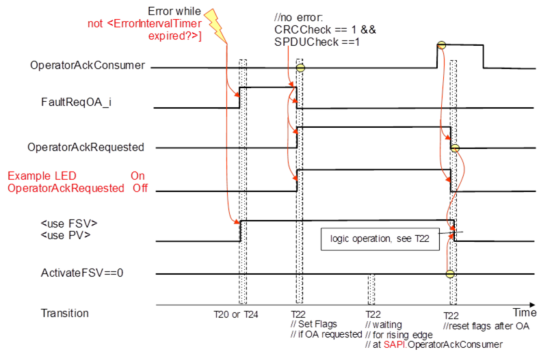
Figure 19 – Sequence diagram for OA
After the error is gone the sequence follows the logic of T22 in Table 35.
[RQ7.15] The ResponseSPDU shall be built by the SafetyProvider by copying RequestSPDU.MonitoringNumber and RequestSPDU.SafetyConsumerID into the ResponseSPDU. In addition, SPDU_ID, Flags, the SafetyData and the NonSafetyData shall be updated. Finally, ResponseSPDU.CRC shall be calculated and appended.
Figure 20 gives an overview over the task of building the ResponseSPDU.
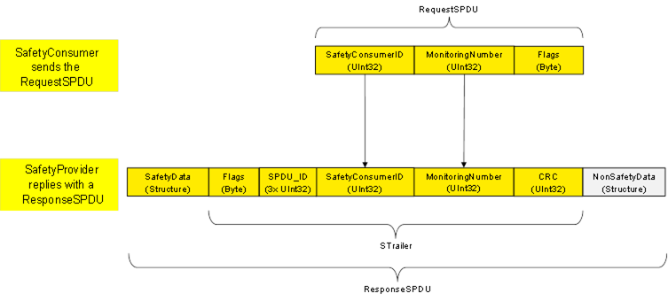
Figure 20 – Overview of task for SafetyProvider
For the ResponseSPDU.Flags, see 7.2.1.6. For the calculation of the SPDU_ID, see 7.2.3.2. For the calculation of the CRC, see 7.2.3.6.
[RQ7.16] SPDU_ID_1, SPDU_ID_2 and SPDU_ID_3 shall be calculated according to Figure 21 and Table 36.
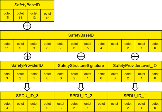
Figure 21 – Calculation of the SPDU_ID
Table 36 – Presentation of the SPDU_ID
|
SPDU_ID_1:= SafetyBaseID (octets 0…3) XOR SafetyProviderLevel_ID (octets 0…3) |
|
SPDU_ID_2:= SafetyBaseID (octets 4…7) XOR SafetyStructureSignature (octets 0…3) |
|
SPDU_ID_3:= SafetyBaseID (octets 8…11) XOR SafetyBaseID (octets 12…15) XOR SafetyProviderID (octets 0…3) |
In case of a mismatch between expected SPDU_ID and actual SPDU_ID, the following rules can be used for diagnostic purposes:
- If all of SPDU_ID_1, SPDU_ID_2, and SPDU_ID_3 differ, there probably is a mismatching SafetyBaseID.
- If SPDU_ID_3 differs, but SPDU_ID_1 and SPDU_ID_2 do not, there is a mismatching SafetyProviderID.
- If SPDU_ID_2 differs, but SPDU_ID_1 and SPDU_ID_3 do not, the structure or identifier of the SafetyData do not match.
- If SPDU_ID_1 differs, but SPDU_ID_2 and SPDU_ID_3 do not, the SafetyProviderLevel does not match.
By these rules, there is a very low probability (<10-9) that a mismatching SafetyBaseID will be misinterpreted. From a practical view, this probability can be ignored.
Figure 22 shows a concrete example of the calculation of SPDU_ID_1, SPDU_ID_2 and SPDU_ID_3. The following input values were chosen for the calculation: SafetyBaseID is the GUID “72962B91-FA75-4AE6-8D28-B404DC7DAF63”, SafetyProviderID has the value 0xE0EA6B40, SafetyStructureSignature has the value 0xDE7329FD and the SafetyProviderLevel_ID is chosen as 0xDEAA9DEE (representing SIL 3).
See OPC 10000-6, 5.2.2.6 for details on the encoding of Guids. The octets from the resulting octet stream are used according to Figure 21, i.e. in “reverse order”.
The resulting SPDU_IDs are as follows: SPDU_ID_1 has the value of 0xAC3CB67F, SPDU_ID_2 has the value of 0x9495D388 and SPDU_ID_3 has the value of 0x87F13E11.
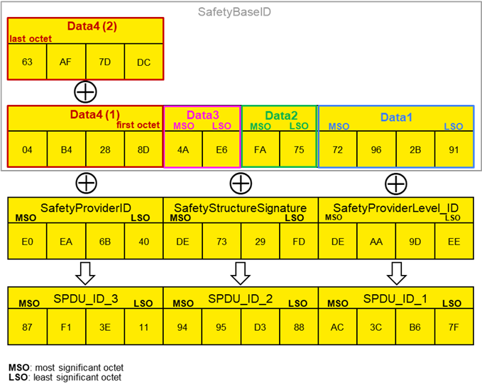
Figure 22 (informative) – Example for the calculation of SPDU_ID_1, SPDU_ID_2 and SPDU_ID_3
The SafetyProviderLevel is the SIL the SafetyProvider implementation (hardware and software) is capable of.
Table 37 – Coding for the SafetyProviderLevel_ID
|
SafetyProviderLevel |
Value of SafetyProviderLevel_ID |
|
0x119128810x647C46540xDEAA9DEE0xAB47F33B |
[RQ7.17] Exactly one of the values provided in Table 37 shall be used as constant code value for SafetyProviderLevel_ID. The values were chosen in such a way that the hamming distance between them becomes maximal (hamming distance of 21).
[RQ7.18] Measures shall be taken to avoid that a SafetyProvider is erroneously using a code value belonging to a SIL that is higher than the SIL it is capable of. For instance, a SafetyProvider capable of SIL 1 to SIL 3 should not be able to accidently use the value 0xAB47F33B used for SIL 4. One way to achieve this is to avoid that this constant appears in the source code of the SafetyProvider at all.
The SafetyProviderLevel is independent to the SIL capability of the provided SafetyData, see 3.1.2.12.
SafetyStructureSignature is used to check the number, DataTypes, and order of application data transmitted in SafetyData. If the SafetyConsumer is expecting anything different than what the SafetyProvider actually provides, SafetyStructureSignature will differ, allowing the SafetyConsumer to enable fail-safe substitute values.
In addition, the identifier of the Structure DataType (SafetyStructureIdentifier) is also taken into account when calculating SafetyStructureSignature. This ensures that the SafetyProvider and the SafetyConsumer are using the same identifier for the Structure DataType, effectively avoiding any confusion.
For instance, if a SafetyProvider defines a Structure with identifier “vec3D_m” comprising three Floats containing a three-dimensional vector in the metric system, this Structure could not be used by a SafetyConsumer expecting a Structure of DataType “vec3D_in” where the vector components are given in inches, or even at a SafetyConsumer expecting a Structure of DataType “orientation”, containing three Floats to define an orientation using Euler angles.
[RQ7.19] SafetyStructureSignature shall be calculated as a 32 bit CRC signature (polynomial: 0x F4ACFB13, see Clause B.1) over SafetyStructureIdentifier (encoding: UTF-8), SafetyStructureSignatureVersion and the sequence of the DataTypeEncodingIDs. After each DataTypeEncodingID, a 16-bit zero-value (0x0000) shall be inserted. All integers shall be encoded using little endian octet ordering. Data shall be processed in reverse order, see Clause B.1. The value “0” shall not be used as a signature. Instead, the value “1” shall be used in this case.
The terminating zero of SafetyStructureIdentifier shall not be considered when calculating the CRC.
[RQ7.20] SafetyStructureIdentifier may be visible in the OPC UA Information Model for diagnostic purposes but shall not be evaluated by the SafetyConsumer during runtime.
[RQ7.21] For all releases up to Release 2.0 of the specification, the value for SafetyStructureSignatureVersion shall be 0x0001.
Example:
SafetyStructureIdentifier,e.g. “Motörhead” = 0x4d 0x6f 0x74 0xc3 0xb6 0x72 0x68 0x65 0x61 0x64
SafetyStructureSignatureVersion:= 0x0001
1. DataType Int16: (DataTypeEncodingId = 0x0004), // see 6.2.5
2. DataType Boolean: (DataTypeEncodingId = 0x0001),
3. DataType Float: (DataTypeEncodingId =0x000a)
= CRC32_Backward(0x4d, 0x6f, 0x74, 0xc3, 0xb6, 0x72, 0x68, 0x65, 0x61, 0x64,
0x01,0x00,
0x04,0x00, 0x00,0x00,
0x01,0x00, 0x00,0x00,
0x0A, 0x00, 0x00, 0x00)
= CRC32_Forward(
0x00, 0x00, 0x00, 0x0A,
0x00, 0x00, 0x00, 0x01,
0x00, 0x00, 0x00, 0x04,
0x00,0x01,
0x64, 0x61, 0x65, 0x68, 0x72, 0xb6, 0xc3, 0x74, 0x6f, 0x4d)
= 0xe2e86173
NOTE 1 The insertion of 0x0000 values after each DataTypeEncodingID allows for introducing arrays in later versions of this document.
NOTE 2 SafetyStructureSignatureVersion is the version of the procedure used to calculate the signature, as defined in requirement RQ7.19. If future releases of this document define an alternative procedure, they will indicate this by using a different version number.
OPC 10000-3, 5.8.2 defines different categories of DataTypes. Regarding the DataTypeEncodingID which is to be used within the SafetyStructureSignature, the following holds:
- For Built-in DataTypes, the ID from Table 1 of OPC 10000-6 is used as DataTypeEncodingID.
- For Simple DataTypes, the DataTypeEncodingID of the Built-in DataType from which they are derived is used.
- As of now, Structured DataTypes (including OptionSets) shall not be used within SafetyData. Arrays are not supported. Instead, multiple variables of the same type are used.
- Enumeration DataTypes are encoded on the wire as Int32 and therefore shall use the DataTypeEncodingID of the Int32 Built-in DataType.
The SafetyProvider calculates the CRC signature (ResponseSPDU.CRC) and sends it to the SafetyConsumer as part of the ResponseSPDU. This enables the SafetyConsumer to check the correctness of the ResponseSPDU including the SafetyData, flags, MNR, SafetyConsumerID and SPDU_ID by recalculating the CRC signature (CRC_calc).
[RQ7.22] The generator polynomial 0x F4ACFB13 shall be used for the 32-Bit CRC signature.
[RQ7.23] If SafetyData is longer than one octet (e.g. if it is of DataType UInt16, Int16 or Float), it shall be decoded and encoded using little endian order in which the least significant octet appears first in the incremental memory address stream.
[RQ7.24] The calculation sequence shall begin with the highest memory address (n) of the STrailer counting back to the lowest memory address (0) and then include also the SafetyData beginning with the highest memory address.
Figure 23 shows the calculation sequence of a ResponseSPDU CRC on a little-endian machine, using an example SafetyData with the following fields:
Int32var1
UInt32var2
UInt16var3
Int16var4
Booleanvar5
For the example given above, the STrailer (without CRC) and SafetyData have a combined length of 34 octets (16 octets STrailer without CRC, 12 octets of SafetyData). The calculation of ResponseSPDU.CRC (SafetyProvider) or CRC_calc (SafetyConsumer) is done in reverse order, from bottom to top. In the example shown in Figure 23, CRC calculation starts at octet index 33 (most significant octet of the MNR) and ends at octet index 0.
NOTE The reverse order ensures that the effectiveness of the CRC mechanism remains independent of any CRCs used within the underlying OPC UA channel, even if it would coincidentally use the same CRC polynomial.
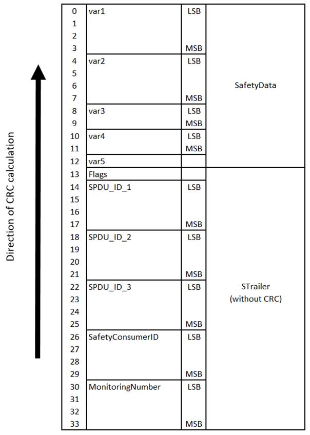
Figure 23 – Calculation of the CRC (on little-endian machines, CRC32_Backward)
An alternative way to calculate the CRC (particularly useful on big-endian machines) is shown in Figure 24. Here, the individual elements of the ResponseSPDU are already arranged in memory in reversed order, and CRC calculation is executed from octet 0 to octet 33.
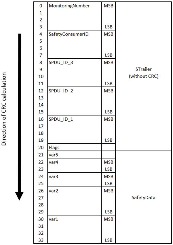
Figure 24 – Calculation of the CRC (on big-endian machines, CRC32_Forward)
[RQ7.25] On the SafetyConsumer, CRC_calc shall be calculated using data received in the ResponseSPDU, and not from expected values.