The MotionDeviceSystemType provides a representation of a motion device system as an entry point to the OPC UA device set. At least one instance of a MotionDeviceSystemType must be instantiated in the DeviceSet. This instance organises the information model of a complete robotics system using instances of the described ObjectTypes. The MotionDeviceSystemType is formally defined in Table 11.
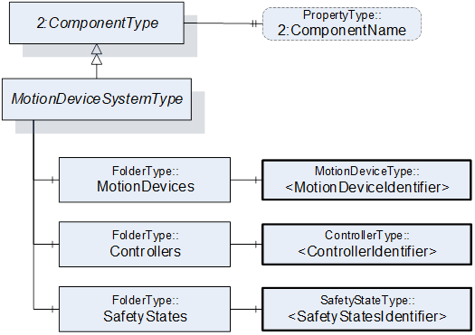
Figure 12 – Overview MotionDeviceSystemType
Table 11 – MotionDeviceSystemType Definition
|
Attribute |
Value |
||||
|
BrowseName |
MotionDeviceSystemType |
||||
|
IsAbstract |
False |
||||
|
References |
Node Class |
BrowseName |
DataType |
TypeDefinition |
Other |
|
Subtype of the ComponentType defined in OPC Unified Architecture for Devices (DI), inheriting the InstanceDeclarations of that Node |
|||||
|
0:HasComponent |
Object |
MotionDevices |
|
0:FolderType |
M |
|
0:HasComponent |
Object |
Controllers |
|
0:FolderType |
M |
|
0:HasComponent |
Object |
SafetyStates |
|
0:FolderType |
M |
|
0:HasProperty |
Variable |
2:ComponentName |
0:LocalizedText |
0:PropertyType |
O |
|
Conformance Units |
|||||
|
Rob MotionDeviceSystem Base |
|||||
The components of the MotionDeviceSystemType have additional subcomponents which are defined in Table 12.
Table 12 – MotionDeviceSystemType Additional Subcomponents
|
Source Path |
Reference |
NodeClass |
BrowseName |
DataType |
TypeDefinition |
Others |
|
MotionDevices |
0:HasComponent |
Object |
<MotionDeviceIdentifier> |
|
MotionDeviceType |
MP |
|
Controllers |
0:HasComponent |
Object |
<ControllerIdentifier> |
|
ControllerType |
MP |
|
SafetyStates |
0:HasComponent |
Object |
<SafetyStateIdentifier> |
|
SafetyStateType |
MP |
A motion device system may consist of multiple motion devices, controllers, and safety systems. References are used to describe the relations between those subsystems. Examples are described in Annex B.
The ComponentName property provides a user writeable name provided by the vendor, integrator, or user of the device. The ComponentName may be a default name given by the vendor. This property is defined by ComponentType defined in OPC 10000-100.
MotionDevices is a container for one or more instances of the MotionDeviceType.
Controllers is a container for one or more instances of the ControllerType.
SafetyStates is a container for one or more instances of the SafetyStatesType.
The MotionDeviceType describes one independent motion device, e.g. a manipulator, a turn table, or a linear axis. Examples are described in Annex B.
A MotionDevice shall have at least one axis and one power train. The MotionDeviceType is formally defined in 7.2.2
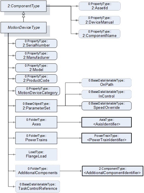
Figure 13 – Overview MotionDeviceType
Table 13 – MotionDeviceType Definition
|
Attribute |
Value |
||||
|
BrowseName |
MotionDeviceType |
||||
|
IsAbstract |
False |
||||
|
References |
Node Class |
BrowseName |
DataType |
TypeDefinition |
Other |
|
Subtype of the ComponentType defined in OPC Unified Architecture for Devices (DI), inheriting the InstanceDeclarations of that Node |
|||||
|
0:HasProperty |
Variable |
2:SerialNumber |
0:String |
0:PropertyType |
M |
|
0:HasProperty |
Variable |
2:Manufacturer |
0:LocalizedText |
0:PropertyType |
M |
|
0:HasProperty |
Variable |
2:Model |
0:LocalizedText |
0:PropertyType |
M |
|
0:HasProperty |
Variable |
2:ProductCode |
0:String |
0:PropertyType |
M |
|
0:HasProperty |
Variable |
MotionDeviceCategory |
MotionDeviceCategoryEnumeration |
0:PropertyType |
M |
|
0:HasComponent |
Variable |
TaskControlReference |
0:NodeId |
0:BaseDataVariableType |
O |
|
0:HasComponent |
Object |
2:ParameterSet |
|
0:BaseObjectType |
M |
|
0:HasComponent |
Object |
Axes |
|
0:FolderType |
M |
|
0:HasComponent |
Object |
PowerTrains |
|
0:FolderType |
M |
|
0:HasComponent |
Object |
FlangeLoad |
|
LoadType |
O |
|
0:HasComponent |
Object |
AdditionalComponents |
|
0:FolderType |
O |
|
0:HasProperty |
Variable |
2:AssetId |
0:String |
0:PropertyType |
O |
|
0:HasProperty |
Variable |
2:DeviceManual |
0:String |
0:PropertyType |
O |
|
0:HasProperty |
Variable |
2:ComponentName |
0:LocalizedText |
0:PropertyType |
O |
|
Conformance Units |
|||||
|
Rob MotionDeviceSystem Base |
|||||
|
Rob MotionDevice AM Extended |
|||||
|
Rob MotionDevice CM Extended |
|||||
|
Rob MotionDevice Flangeload |
|||||
|
Rob TC Relationship |
|||||
The components of the MotionDeviceType have additional subcomponents which are defined in Table 14.
Table 14 – MotionDeviceType Additional Subcomponents
|
Source Path |
Reference |
NodeClass |
BrowseName |
DataType |
TypeDefinition |
Other |
|
2:ParameterSet |
0:HasComponent |
Variable |
OnPath |
0:Boolean |
0:BaseDataVariableType |
O |
|
2:ParameterSet |
0:HasComponent |
Variable |
InControl |
0:Boolean |
0:BaseDataVariableType |
O |
|
2:ParameterSet |
0:HasComponent |
Variable |
SpeedOverride |
0:Double |
0:BaseDataVariableType |
M |
|
Axes |
0:HasComponent |
Object |
<AxisIdentifier> |
|
AxisType |
MP |
|
PowerTrains |
0:HasComponent |
Object |
<PowerTrainIdentifier> |
|
PowerTrainType |
MP |
|
AdditionalComponents |
0:HasComponent |
Object |
<AdditionalComponentIdentifier> |
|
0:BaseObjectType |
MP |
The SerialNumber property is a unique production number assigned by the manufacturer of the device. This is often stamped on the outside of the device and may be used for traceability and warranty purposes. This property is derived from ComponentType defined in OPC 10000-100.
The Manufacturer property provides the name of the company that manufactured the device. This property is derived from ComponentType defined in OPC 10000-100.
The Model property provides the name of the product. This property is derived from ComponentType defined in OPC 10000-100.
The ProductCode property provides a unique combination of numbers and letters used to identify the product. It may be the order information displayed on type shields or in ERP systems. This property is derived from ComponentType defined in OPC 10000-100.
The AssetId property is a user writable alphanumeric character sequence uniquely identifying a component. The vendor, integrator or user of the device provides the ID. It contains typically an identifier in a branch, use case or user specific naming scheme. This could be for example a reference to an electric scheme. For electric schemes typically EN 81346-2 is used. A use case could be to build up a location-oriented view in a spare part management client software. It enables to identify parts with the same article number which is not possible if this entry is not used. This property is defined by ComponentType defined in OPC 10000-100.
The DeviceManual property allows specifying an address of the user manual for the device. It may be a pathname in the file system or a URL (Web address). This property is defined by ComponentType defined in OPC 10000-100.
The ComponentName property provides a user writeable name provided by the vendor, integrator, or user of the device. The ComponentName may be a default name given by the vendor. This property is defined by ComponentType defined in OPC 10000-100.
FlangeLoad provides data for the load at the flange or mounting point of the motion device.
The variable MotionDeviceCategory provides the kind of motion device defined by MotionDeviceCategoryEnumeration based on ISO 8373 (10.1).
The Variable TaskControlReference provides a NodeId pointing to the instance of TaskControlOperationType defined in 7.15, which controls this motion device in combination with the loaded program.
Description of ParameterSet of MotionDeviceType:
- Variable OnPath: The variable OnPath is true if the motion device is on or near enough the planned program path such that program execution can continue. If the MotionDevice deviates too much from this path in case of errors or an emergency stop, this value becomes false. If OnPath is false, the motion device needs repositioning to continue program execution.
- Variable InControl: The variable InControl provides the information if the actuators (in most cases a motor) of the motion device are powered up and in control: "true". The motion device might be in a standstill.
- Variable SpeedOverride: The SpeedOverride provides the current speed setting in percent of programmed speed (0 - 100%).
Axes is a container for one or more instances of the AxisType (7.3).
PowerTrains is a container for one or more instances of the PowerTrainType.
AdditionalComponents is a container for one or more instances of any other ObjectType (any subtype of 0:BaseObjectType). The listed components are installed at the motion device, e.g. an IO-board.
NOTE: Components like motors or gears of a motion device are placed inside the power train object and not inside this AdditionalComponents container. The intention of this folder is to integrate devices which are defined in companion specifications that use OPC 10000-100 ComponentType. From this specification, only instances of AuxiliaryComponentType and DriveType can be used in this container.
The AxisType describes an axis of a motion device. It is formally defined in Table 15.
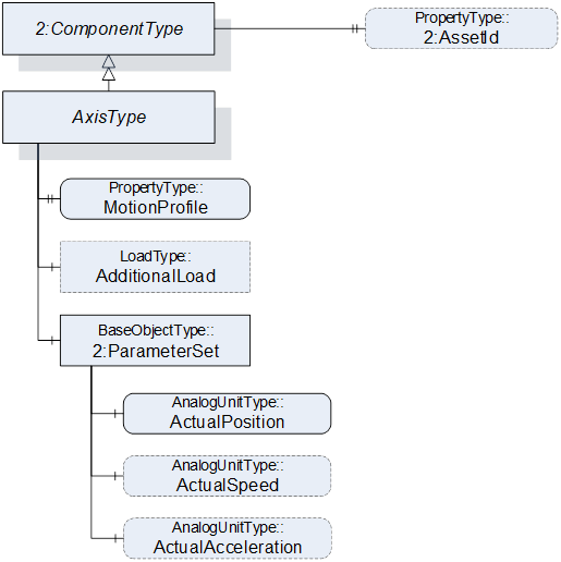
Table 15 – AxisType Definition
|
Attribute |
Value |
||||
|
BrowseName |
AxisType |
||||
|
IsAbstract |
False |
||||
|
References |
Node Class |
BrowseName |
DataType |
TypeDefinition |
Other |
|
Subtype of the ComponentType defined in OPC Unified Architecture for Devices (DI), inheriting the InstanceDeclarations of that Node |
|||||
|
0:HasProperty |
Variable |
MotionProfile |
AxisMotionProfileEnumeration |
0:PropertyType |
M |
|
0:HasComponent |
Object |
AdditionalLoad |
|
LoadType |
O |
|
0:HasComponent |
Object |
2:ParameterSet |
|
0:BaseObjectType |
M |
|
Requires |
Object |
<PowerTrainIdentifier> |
|
PowerTrainType |
OP |
|
0:HasProperty |
Variable |
2:AssetId |
0:String |
0:PropertyType |
O |
|
Conformance Units |
|||||
|
Rob MotionDeviceSystem Base |
|||||
|
Rob Axis AM Extended |
|||||
|
Rob Axis CM Extended |
|||||
|
Rob Axis AdditionalLoad |
|||||
The components of the AxisType have additional subcomponents which are defined in Table 16.
Table 16 – AxisType Additional Subcomponents
|
Source Path |
Reference |
NodeClass |
BrowseName |
DataType |
TypeDefinition |
Others |
|
2:ParameterSet |
0:HasComponent |
Variable |
ActualPosition |
0:Double |
0:AnalogUnitType |
M |
|
2:ParameterSet |
0:HasComponent |
Variable |
ActualSpeed |
0:Double |
0:AnalogUnitType |
O |
|
2:ParameterSet |
0:HasComponent |
Variable |
ActualAcceleration |
0:Double |
0:AnalogUnitType |
O |
The AssetId property is a user writable alphanumeric character sequence uniquely identifying a component. The vendor, integrator or user of the device provides the ID. It contains typically an identifier in a branch, use case or user specific naming scheme. This could be for example a reference to an electric scheme. For electric schemes typically EN 81346-2 is used. The AssetId of the AxisType provides a manufacturer-specific axis identifier within the control system. This property is defined by ComponentType defined in OPC 10000-100.
The MotionProfile property provides the kind of axis motion as defined by the AxisMotionProfileEnumeration (10.2)
AdditionalLoad provides data for the load that is mounted on this axis, e.g., a transformer for welding.
The Requires reference provides the relationship of axes to power trains. For complex kinematics this does not need to be a one-to-one relationship, because more than one power train might influence the motion of one axis. This reference connects all power trains to an axis that must be actively driven when only this axis should move and all other axes should stand still.
Virtual axes that are not actively driven by a power train do not have this reference. The InverseName is IsRequiredBy.
Description of ParameterSet of AxisType:
- Variable ActualPosition: The ActualPosition variable provides the current position of the axis and may have limits. If the axis has physical limits, the EURange property of the AnalogUnitType shall be provided.
- Variable ActualSpeed: The ActualSpeed variable provides the axis speed. Applicable speed limits of the axis shall be provided by the EURange property of the AnalogUnitType.
- Variable ActualAcceleration: The ActualAcceleration variable provides the axis acceleration. Applicable acceleration limits of the axis shall be provided by the EURange property of the AnalogUnitType.
A power train typically consists of one motor and gear to provide the required torque. Often there is a one-to-one relation between axes and power trains, but it is also possible to have axis coupling and thus one power train can move multiple axes and one axis can be moved by multiple power trains. One power train can have multiple drives, motors, and gears when these components move logically the same axes, for example in a master/slave setup. Examples are described in Annex B. The PowerTrainType represents instances of power trains of a motion device and is formally defined in
Table 17.
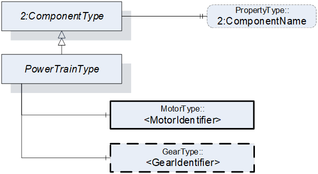
Figure 15 – Overview PowerTrainType
Table 17 – PowerTrainType Definition
|
Attribute |
Value |
||||
|
BrowseName |
PowerTrainType |
||||
|
IsAbstract |
False |
||||
|
References |
Node Class |
BrowseName |
DataType |
TypeDefinition |
Other |
|
Subtype of the ComponentType defined in OPC Unified Architecture for Devices (DI), inheriting the InstanceDeclarations of that Node |
|||||
|
0:HasComponent |
Object |
<MotorIdentifier> |
|
MotorType |
MP |
|
0:HasComponent |
Object |
<GearIdentifier> |
|
GearType |
OP |
|
Moves |
Object |
<AxisIdentifier> |
|
AxisType |
OP |
|
HasSlave |
Object |
<PowerTrainIdentifier> |
|
PowerTrainType |
OP |
|
0:HasProperty |
Variable |
2:ComponentName |
0:LocalizedText |
0:PropertyType |
O |
|
Conformance Units |
|||||
|
Rob MotionDeviceSystem Base |
|||||
|
Rob PowerTrain AM Extended |
|||||
The ComponentName property provides a user writable name provided by the vendor, integrator, or user of the device. The ComponentName may be a default name given by the vendor.
The ComponentName of the PowerTrainType provides a manufacturer-specific power train identifier within the control system.
This property is defined by ComponentType defined in OPC 10000-100.
<MotorIdentifier> indicates that a power train contains one or more motors represented by MotorType instances.
The IsConnectedTo ReferenceType defined in 8.6 is intended to provide the relationship between a motor and a gear of a power train.
<GearIdentifier> indicates that a power train may contain one or more gears represented by GearType instances.
The IsConnectedTo ReferenceType defined in 8.6 is intended to provide the relationship between a motor and a gear of a power train.
Moves is a reference to provide the relationship of power trains to axes. For complex kinematics this does not need to be a one-to-one relationship, because a power train might influence the motion of more than one axis. This reference connects all axis to a power train that that move when only this power train moves and all other powertrains stand still. The InverseName is IsMovedBy.
HasSlave is a reference to provide the master-slave relationship of power trains which provide torque for a common axis. The InverseName is IsSlaveOf.
The MotorType describes a motor in a power train. It is formally defined in Table 18.
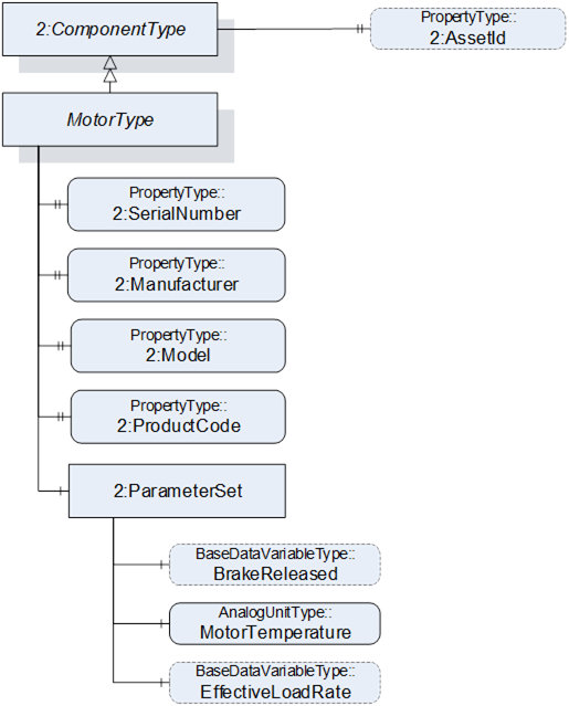
Figure 16 – Overview MotorType
Table 18 – MotorType Definition
|
Attribute |
Value |
||||
|
BrowseName |
MotorType |
||||
|
IsAbstract |
False |
||||
|
References |
Node Class |
BrowseName |
DataType |
TypeDefinition |
Other |
|
Subtype of the ComponentType defined in OPC Unified Architecture for Devices (DI), inheriting the InstanceDeclarations of that Node |
|||||
|
0:HasProperty |
Variable |
2:SerialNumber |
0:String |
0:PropertyType |
M |
|
0:HasProperty |
Variable |
2:Manufacturer |
0:LocalizedText |
0:PropertyType |
M |
|
0:HasProperty |
Variable |
2:Model |
0:LocalizedText |
0:PropertyType |
M |
|
0:HasProperty |
Variable |
2:ProductCode |
0:String |
0:PropertyType |
M |
|
0:HasComponent |
Object |
2:ParameterSet |
|
0:BaseObjectType |
M |
|
IsDrivenBy |
Object |
<DriveIdentifier> |
|
0:BaseObjectType |
OP |
|
0:HasProperty |
Variable |
2:AssetId |
0:String |
0:PropertyType |
O |
|
Conformance Units |
|||||
|
Rob MotionDeviceSystem Base |
|||||
|
Rob Motor AM Extended |
|||||
|
Rob Motor CM Extended |
|||||
The components of the MotorType have additional subcomponents which are defined in Table 19.
Table 19 – MotorType Additional Subcomponents
|
Source Path |
Reference |
NodeClass |
BrowseName |
DataType |
TypeDefinition |
Others |
|
2:ParameterSet |
0:HasComponent |
Variable |
BrakeReleased |
0:Boolean |
0:BaseDataVariableType |
O |
|
2:ParameterSet |
0:HasComponent |
Variable |
MotorTemperature |
0:Double |
AnalogUnitType |
M |
|
2:ParameterSet |
0:HasComponent |
Variable |
EffectiveLoadRate |
0:UInt16 |
0:BaseDataVariableType |
O |
The SerialNumber property is a unique production number assigned by the manufacturer of the device. This is often stamped on the outside of the device and may be used for traceability and warranty purposes. This property is derived from ComponentType defined in OPC 10000-100.
The Manufacturer property provides the name of the company that manufactured the device. This property is derived from ComponentType defined in OPC 10000-100.
The Model property provides the name of the product. This property is derived from ComponentType defined in OPC 10000-100.
The ProductCode property provides a unique combination of numbers and letters used to identify the product. It may be the order information displayed on type shields or in ERP systems. This property is derived from ComponentType defined in OPC 10000-100.
The AssetId property is a user writable alphanumeric character sequence uniquely identifying a component. The vendor, integrator or user of the device provides the ID. It contains typically an identifier in a branch, use case or user specific naming scheme.
This could be for example a reference to an electric scheme. For electric schemes typically EN 81346-2 is used.
A use case could be to build up a location-oriented view in a spare part management client software. It enables to identify parts with the same article number which is not possible if this entry is not used.
This property is defined by ComponentType defined in OPC 10000-100.
IsDrivenBy is a reference to provide a relationship from a motor to a drive, which can be a multi-slot-drive or single slot drive. The TypeDefinition of the reference destination as BaseObjectType provides the possibility to point to a slot of a multi-slot-drive or a motor-integrated-drive. If this reference points to a physical drive (and not a drive slot) it should point to an DriveType.
Annex B.10 shows different possibilities of usage.
Description of ParameterSet of MotorType:
- Variable BrakeReleased: The BrakeReleased is an optional variable used only for motors with brakes. If BrakeReleased is TRUE the motor is free to run. FALSE means that the motor shaft is locked by the brake.
- Variable MotorTemperature: The MotorTemperature provides the temperature of the motor. If there is no temperature sensor the value is set to “null”.
- Variable EffectiveLoadRate: EffectiveLoadRate is expressed as a percentage of maximum continuous load. The Joule integral is typically used to calculate the current load, i.e.:
Duration should be defined and documented by the vendor.
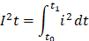
The GearType describes a gear in a power train, e.g. a gear box or a spindle. It is formally defined in Table 20.
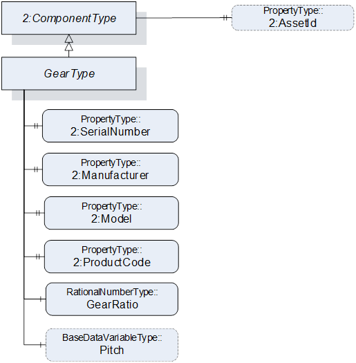
Table 20 – GearType Definition
|
Attribute |
Value |
||||
|
BrowseName |
GearType |
||||
|
IsAbstract |
False |
||||
|
References |
Node Class |
BrowseName |
DataType |
TypeDefinition |
Other |
|
Subtype of the ComponentType defined in OPC Unified Architecture for Devices (DI), inheriting the InstanceDeclarations of that Node |
|||||
|
0:HasProperty |
Variable |
2:SerialNumber |
0:String |
0:PropertyType |
M |
|
0:HasProperty |
Variable |
2:Manufacturer |
0:LocalizedText |
0:PropertyType |
M |
|
0:HasProperty |
Variable |
2:Model |
0:LocalizedText |
0:PropertyType |
M |
|
0:HasProperty |
Variable |
2:ProductCode |
0:String |
0:PropertyType |
M |
|
0:HasComponent |
Variable |
GearRatio |
0:RationalNumber |
0:RationalNumberType |
M |
|
0:HasComponent |
Variable |
Pitch |
0:Double |
0:BaseDataVariableType |
O |
|
0:HasProperty |
Variable |
2:AssetId |
0:String |
0:PropertyType |
O |
|
Conformance Units |
|||||
|
Rob Gear CM Extended |
|||||
|
Rob Gear AM Extended |
|||||
In case of a one-to-one relation between powertrains and axes, gear ratio and pitch may reflect the relation between motor and axis velocities. This is not possible when axis coupling is involved because different ratios for all motor-axis combinations may be needed. Additionally, there could be a nonlinear coupling between the load side of the gear box and the axis. Thus, GearRatio and Pitch only reflect the properties of the physical gear box and it may not be possible to use these values to transform between axis and motor movements.
The SerialNumber property is a unique production number assigned by the manufacturer of the device. This is often stamped on the outside of the device and may be used for traceability and warranty purposes. This property is derived from ComponentType defined in OPC 10000-100.
The Manufacturer property provides the name of the company that manufactured the device. This property is derived from ComponentType defined in OPC 10000-100.
The Model property provides the name of the product. This property is derived from ComponentType defined in OPC 10000-100.
The ProductCode property provides a unique combination of numbers and letters used to identify the product. It may be the order information displayed on type shields or in ERP systems. This property is derived from ComponentType defined in OPC 10000-100.
The AssetId property is a user writable alphanumeric character sequence uniquely identifying a component. The vendor, integrator or user of the device provides the ID. It contains typically an identifier in a branch, use case or user specific naming scheme. This could be for example a reference to an electric scheme. For electric schemes typically EN 81346-2 is used. A use case could be to build up a location-oriented view in a spare part management client software. It enables to identify parts with the same article number which is not possible if this entry is not used. This property is defined by ComponentType defined in OPC 10000-100.
GearRatio is the transmission ratio of the gear expressed as a fraction as input velocity (motor side) by output velocity (load side).
Pitch describes the distance covered in millimetres (mm) for linear motion per one revolution of the output side of the driving unit. Pitch is used in combination with GearRatio to describe the overall transmission from input to output of the gear.
Calculation formula:

SafetyStateType describes the safety states of the motion devices and controllers. One motion device system is associated with one or more instances of the SafetyStateType.
The SafetyStateType was modelled directly in the MotionDeviceSystemType for the following reasons:
- The manufacturers of systems have different concepts where safety is functional located, e.g. the hardware and software implementation.
- The safety state typically applies to the entire robotic system. If multiple safety state instances are implemented in robotic systems, these can be represented by individual instances of the SafetyStateType and associated with the controller by reference.
The safety state is for informational purpose only and not intended for use with functional safety applications as defined in IEC 61508.
The SafetyStateType is formally defined in Table 21.
Figure 18 – Overview SafetyStateType
Table 21 – SafetyStateType Definition
|
Attribute |
Value |
||||
|
BrowseName |
SafetyStateType |
||||
|
IsAbstract |
False |
||||
|
References |
Node Class |
BrowseName |
DataType |
TypeDefinition |
Other |
|
Subtype of the ComponentType defined in OPC Unified Architecture for Devices (DI), inheriting the InstanceDeclarations of that Node |
|||||
|
0:HasComponent |
Object |
EmergencyStopFunctions |
|
0:FolderType |
O |
|
0:HasComponent |
Object |
ProtectiveStopFunctions |
|
0:FolderType |
O |
|
0:HasComponent |
Object |
2:ParameterSet |
|
0:BaseObjectType |
M |
|
0:HasProperty |
Variable |
2:ComponentName |
0:LocalizedText |
0:PropertyType |
O |
|
Conformance Units |
|||||
|
Rob MotionDeviceSystem Base |
|||||
|
Rob Emergency Stop Function |
|||||
|
Rob Protective Stop Function |
|||||
The components of the SafetyStateType have additional subcomponents which are defined in Table 22.
Table 22 – SafetyStateType Additional Subcomponents
|
Source Path |
Reference |
NodeClass |
BrowseName |
DataType |
TypeDefinition |
Others |
|
EmergencyStopFunctions |
0:HasComponent |
Object |
<EmergencyStopFunctionIdentifier> |
|
EmergencyStopFunctionType |
MP |
|
ProtectiveStopFunctions |
0:HasComponent |
Object |
<ProtectiveStopFunctionIdentifier> |
|
ProtectiveStopFunctionType |
MP |
|
2:ParameterSet |
0:HasComponent |
Variable |
OperationalMode |
OperationalModeEnumeration |
0:BaseDataVariableType |
M |
|
2:ParameterSet |
0:HasComponent |
Variable |
EmergencyStop |
0:Boolean |
0:BaseDataVariableType |
M |
|
2:ParameterSet |
0:HasComponent |
Variable |
ProtectiveStop |
0:Boolean |
0:BaseDataVariableType |
M |
The ComponentName property provides a user writable name provided by the vendor, integrator, or user of the device. The ComponentName may be a default name given by the vendor. This property is defined by ComponentType defined in OPC 10000-100.
EmergencyStopFunctions is a container for one or more instances of the EmergencyStopFunctionType. The number and names of emergency stop functions is vendor specific. When provided, this object contains a list of all emergency stop functions with names and current state. See description of EmergencyStopFunctionType for examples of emergency stop functions.
ProtectiveStopFunctions is a container for one or more instances of the ProtectiveStopFunctionType. The number and names of protective stop functions is vendor specific. When provided, this object contains a list of all protective stop functions with names and current state. See description of ProtectiveStopFunctionType for examples of protective stop functions.
Description of ParameterSet of SafetyStateType:
- The OperationalMode variable provides information about the current operational mode. Allowed values are described in OperationalModeEnumeration (10.4).
- The EmergencyStop variable is TRUE if one or more of the emergency stop functions in the robot system are active, FALSE otherwise. If the EmergencyStopFunctions object is provided, then the value of this variable is TRUE if one or more of the listed emergency stop functions are active.
- The ProtectiveStop variable is TRUE if one or more of the enabled protective stop functions in the system are active, FALSE otherwise. If the ProtectiveStopFunctions object is provided, then the value of this variable is TRUE if one or more of the listed protective stop functions are enabled and active.
According to ISO 10218-1:2011 Ch.5.5.2 Emergency stop, the robot shall have one or more emergency stop functions. This shall be done with the help of the EmergencyStopFunctionType is defined in Table 23.
Table 23 – EmergencyStopFunctionType Definition
|
Attribute |
Value |
||||
|
BrowseName |
EmergencyStopFunctionType |
||||
|
References |
Node Class |
BrowseName |
DataType |
TypeDefinition |
Modelling Rule |
|
Subtype of the BaseObjectType defined in OPC Unified Architecture |
|||||
|
0:HasProperty |
Variable |
Name |
0:String |
0:PropertyType |
M |
|
0:HasComponent |
Variable |
Active |
0:Boolean |
0:BaseDataVariableType |
M |
|
Conformance Units |
|||||
|
Rob Emergency Stop Function |
|||||
The Name of the EmergencyStopFunctionType provides a manufacturer-specific emergency stop function identifier within the safety system. The only named emergency stop function in the ISO 10218-1:2011 standard is the "Pendant emergency stop function". Other than that, the standard does not give any indication on naming of emergency stop functions.
The Active variable is TRUE if this emergency stop function is active, e.g. that the emergency stop button is pressed, FALSE otherwise.
According to ISO 10218-1:2011 Ch.5.5.3 the robot shall have one or more protective stop functions designed for the connection of external protective devices. This type is formally defined in Table 24
Table 24 – ProtectiveStopFunctionType Definition
|
Attribute |
Value |
||||
|
BrowseName |
ProtectiveStopFunctionType |
||||
|
References |
NodeClass |
BrowseName |
DataType |
TypeDefinition |
Others |
|
Subtype of the BaseObjectType defined in OPC Unified Architecture |
|||||
|
0:HasProperty |
Variable |
Name |
0:String |
0:PropertyType |
M |
|
0:HasComponent |
Variable |
Enabled |
0:Boolean |
0:BaseDataVariableType |
M |
|
0:HasComponent |
Variable |
Active |
0:Boolean |
0:BaseDataVariableType |
M |
|
Conformance Units |
|||||
|
Rob Protective Stop Function |
|||||
The Name of the ProtectiveStopFunctionType provides a manufacturer-specific protective stop function identifier within the safety system.
The Enabled variable is TRUE if this protective stop function is currently supervising the system, FALSE otherwise. A protective stop function may or may not be always enabled, e.g. the protective stop function of the safety doors is typically enabled in automatic operational mode and disabled in manual mode. On the other hand, for example, the protective stop function of the teach pendant enabling device is enabled in manual modes and disabled in automatic modes.
The Active variable is TRUE if this protective stop function is active, i.e. that a stop is initiated, FALSE otherwise. If Enabled is FALSE then Active shall be FALSE.
Examples
The table below shows an example with a door interlock function. In this example, the door is only monitored during automatic modes. During manual modes, the operators may open the door without causing a protective stop.
Table 25 – Door Interlock Protective Stop Example
|
|
Automatic Mode |
Manual Mode |
||
|
Door interlock |
Enabled |
Active |
Enabled |
Active |
|
Door closed |
TRUE |
FALSE |
FALSE |
FALSE |
|
Door open |
TRUE |
TRUE |
FALSE |
FALSE |
The next example shows how the three-position enabling device normally found on teach pendants is processed. In this case it does not matter if the enabling device is pressed or not during automatic modes, while in manual modes, a protective stop is active if the enabling device is released or fully pressed.
Table 26 – Teach Pendant Enabling Device Protective Stop Example
|
|
Automatic Mode |
Manual Mode |
||
|
Teach Pendant Enabling Device |
Enabled |
Active |
Enabled |
Active |
|
Released |
FALSE |
FALSE |
TRUE |
TRUE |
|
Middle position |
FALSE |
FALSE |
TRUE |
FALSE |
|
Fully pressed (panic) |
FALSE |
FALSE |
TRUE |
TRUE |
The OperationStateMachineType provides an abstract state machine for operation. The state machine can be used for entities whose states can be represented by Idle, Ready or Executing and which can be started and stopped.
At the system and task control levels, concrete state machine types are derived from the OperationStateMachineType. The states of these state machines can be further enhanced with Substate machines.
The overview of the state machine with all transitions is shown in Figure 19.
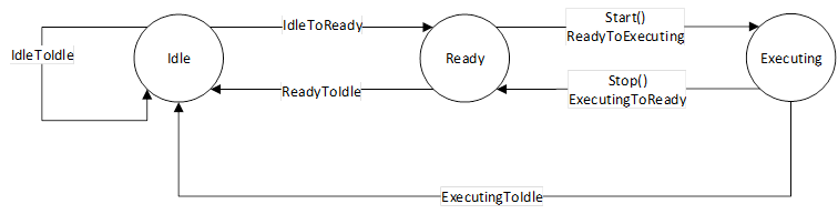
Figure 19 – OperationStateMachine.
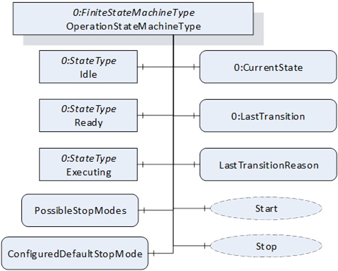
Figure 20 – The OperationStateMachineType
Figure 20 shows the OPC UA representation of the OperationStateMachineType, the transitions between the states have not been shown for the sake of simplicity. The OperationStateMachineType is formally defined in Table 65.
Table 27 – OperationStateMachineType Definition
|
Attribute |
Value |
||||
|
BrowseName |
OperationStateMachineType |
||||
|
IsAbstract |
True |
||||
|
References |
Node Class |
BrowseName |
DataType |
TypeDefinition |
Other |
|
Subtype of the FiniteStateMachineType defined in OPC 10000-5. |
|||||
|
0:HasComponent |
Variable |
LastTransitionReason |
0:Int16 |
0:MultiStateValueDiscreteType |
M |
|
0:HasComponent |
Variable |
PossibleStopModes |
0:EnumValueType[] |
0:BaseDataVariableType |
O |
|
0:HasComponent |
Variable |
ConfiguredDefaultStopMode |
0:Int16 |
0:BaseDataVariableType |
O |
|
0:HasComponent |
Object |
Idle |
|
0:StateType |
|
|
0:HasComponent |
Object |
Ready |
|
0:StateType |
|
|
0:HasComponent |
Object |
Executing |
|
0:StateType |
|
|
0:HasComponent |
Object |
ReadyToIdle |
|
0:TransitionType |
|
|
0:HasComponent |
Object |
IdleToReady |
|
0:TransitionType |
|
|
0:HasComponent |
Object |
ExecutingToReady |
|
0:TransitionType |
|
|
0:HasComponent |
Object |
ReadyToExecuting |
|
0:TransitionType |
|
|
0:HasComponent |
Object |
ExecutingToIdle |
|
0:TransitionType |
|
|
0:HasComponent |
Object |
IdleToIdle |
|
0:TransitionType |
|
|
0:HasComponent |
Method |
Start |
|
|
O |
|
0:HasComponent |
Method |
Stop |
|
|
O |
|
Inherited from FiniteStateMachineType |
|||||
|
0:HasComponent |
Variable |
LastTransition |
0:LocalizedText |
0:FiniteTransitionVariableType |
M |
|
0:GeneratesEvent |
ObjectType |
TransitionEventType |
|
|
O |
The states of the OperationStateMachineType are described in Table 28.
The component Variables of the OperationStateMachineType have additional Attributes defined in Table 30.
Table 28 – OperationStateMachineType State Descriptions
|
StateName |
Description |
|
Idle |
Entity is not in a condition to start execution. |
|
Ready |
Entity is in a condition to start execution. |
|
Executing |
Entity is in a condition of execution. |
The Variable LastTransitionReason provides the reason for the LastTransition. The EnumValue and ValueAsText of this 0:MultiStateValueDiscreteType are described in Table 29. This specification does not define an explicit error state. The LastTransitionReason indicates if a state change was caused due to an error.
Table 29 – Values for LastTransitionReason
|
EnumValue |
ValueAsText |
Description |
|
0 |
Unknown |
Caused by an unknown reason |
|
1 |
External |
Caused by external operation |
|
2 |
Direct |
Caused by direct operation |
|
3 |
System |
Caused by system specific behaviour |
|
4 |
Error |
Caused by an error |
|
5 |
Application |
Caused explicitly by end user program logic |
The component Variables of the OperationStateMachineType have additional Attributes defined in Table 30.
Table 30 – OperationStateMachineType Attribute values for child nodes
|
BrowsePath |
Value Attribute |
Description Attribute |
||
|
[ {"Value":0,"DisplayName":"Unknown","Description":"Caused by an unknown reason"}, {"Value":1,"DisplayName":"External","Description":"Caused by external operation"}, {"Value":2,"DisplayName":"Direct","Description":"Caused by direct operation"}, {"Value":3,"DisplayName":"System","Description":"Caused by system specific behavior"}, {"Value":4,"DisplayName":"Error", "Description": "Caused by an error"}, {"Value":5,"DisplayName":"Application","Description":"Caused explicitly by end user program logic"} ] |
|
LastTransitionReason EnumValues 1 and 2 describe where an operation was initiated, which reasoned the last transition. External means that the operation was initiated by a control station, which is not part of the robot system, e.g a cell PLC. Direct means that the operation was initiated by a control station, which is part of the robot system, e.g. the teach pendant.
The Variable PossibleStopModes is an array of EnumValueType, which contains a list of supported stop modes (see Table 31).
Table 31 – PossibleStopMode Array Values
|
Nr. |
Stop Mode |
Description |
|
1 |
OnPath |
Stop program execution in a controlled manner along the programmed path. |
|
2 |
EndOfCycle |
Stop program execution when the current production cycle has been finished. |
|
3 |
ProcessStop |
Application dependent stop instruction that stops program execution at a "favourable" point for the application, e.g. at the end of a paint stroke or sealing bead. |
|
4 |
QuickStop |
This stop is performed by ramping down motion as fast as possible using optimum motor performance. The robot may not stay on the path. |
|
5 |
EndOfInstruction |
This stop can be used to stop the program execution when the current instruction is completed. |
|
>=1000 |
|
Reserved for other OPC UA Companion Specifications |
|
>=2000 |
|
Used for vendor specific stop modes |
Table 32 – OperationStateMachineType Attribute values for child nodes
|
BrowsePath |
Value Attribute |
Description Attribute |
|
PossibleStopModes |
[ {"Value": 1, "DisplayName": "OnPath", "Description": "Stop program execution in a controlled manner along the programmed path"}, {"Value": 2, "DisplayName": "EndOfCycle", "Description": "Stop program execution when the current production cycle has been finished"}, {"Value": 3, "DisplayName": "ProcessStop", "Description": "Application dependent stop instruction that stops program execution at a favourable point for the application, e.g. at the end of a paint stroke or sealing bead"}, {"Value": 4, "DisplayName": "QuickStop", "Description": "This stop is performed by ramping down motion as fast as possible using optimum motor performance. The robot may not stay on the path”}, {"Value": 5, "DisplayName": "EndOfInstruction", "Description": "This stop can be used to stop the program execution when the current instruction is completed"} ] |
|
The Variable ConfiguredDefaultStopMode is an integer, which contains the value of the configured stop mode for this system. This shall be one of the values in the PossibleStopModes array.
The Variable LastTransition, inherited from the FiniteStateMachineType, is defined as mandatory in the OperationStateMachineType.
The transitions of the OperationStateMachineType are described in Table 33.
Table 33 – OperationStateMachineType Transition Descriptions
|
TransitionName |
Description |
|
IdleToReady |
Changes from Idle to Ready. |
|
IdleToIdle |
Changes from Idle to Idle. |
|
ReadyToIdle |
Changes from Ready to Idle. |
|
ReadyToExecuting |
Changes from Ready to Executing. |
|
ExecutingToReady |
Changes from Executing to Ready. |
|
ExecutingToIdle |
Changes from Executing to Idle. |
The components of the OperationStateMachineType have additional references which are defined in Table 69.
Table 34 – OperationStateMachineType Additional References
|
SourceBrowsePath |
Reference Type |
Is Forward |
TargetBrowsePath |
|
IdleToIdle |
0:FromState |
True |
Idle |
0:ToState |
True |
Idle |
0:HasEffect |
True |
TransitionEventType |
|
IdleToReady |
0:FromState |
True |
Idle |
|
|
0:ToState |
True |
Ready |
|
|
0:HasEffect |
True |
TransitionEventType |
|
ReadyToIdle |
0:FromState |
True |
Ready |
|
|
0:ToState |
True |
Idle |
|
|
0:HasEffect |
True |
TransitionEventType |
|
ReadyToExecuting |
0:FromState |
True |
Ready |
0:ToState |
True |
Executing |
0:HasCause |
True |
Start |
0:HasEffect |
True |
TransitionEventType |
|
ExecutingToReady |
0:FromState |
True |
Executing |
0:ToState |
True |
Ready |
0:HasCause |
True |
Stop |
0:HasEffect |
True |
TransitionEventType |
|
ExecutingToIdle |
0:FromState |
True |
Executing |
0:ToState |
True |
Idle |
0:HasEffect |
True |
TransitionEventType |
The component Variables of the OperationStateMachine have additional Attributes defined in the table below.
Table 35 – OperationStateMachineType Attribute values for child Nodes
|
BrowsePath |
Value Attribute |
||
|
1 |
||
|
2 |
||
|
3 |
||
|
1 |
||
|
2 |
||
|
3 |
||
|
4 |
||
|
5 |
||
|
6 |
The signature of this Method is specified below.
Signature
Start (
[out]0:Int32Status
);
The Start Method is called by a Client to start execution of the entity which is represented by the state machine.
Table 36 – Start Method Arguments
|
Argument |
Description |
|
Status |
0 – OK Values > 0 are reserved for errors defined by this and future standards. Values < 0 shall be used for application-specific errors. |
The possible Method result codes are formally defined in Table 37.
Table 37 – Method Result Codes (defined in Call Service)
|
Result Code |
Description |
|
Good |
The operation succeeded |
|
Bad_InternalError |
The operation failed because of an internal error |
|
Bad_ResourceUnavailable |
The Method cannot be executed because a required resource is locked. |
|
Bad_UserAccessDenied |
The caller is not allowed to execute this Method. |
The Start Method representation in the AddressSpace is formally defined in table below.
Table 38 – Start Method AddressSpace definition.
|
Attribute |
Value |
||||
|
BrowseName |
Start |
||||
|
References |
NodeClass |
BrowseName |
DataType |
TypeDefinition |
ModellingRule |
|
0:HasProperty |
Variable |
0:OutputArguments |
0:Argument[] |
0:PropertyType |
0:Mandatory |
The signature of this Method is specified below.
Signature
Stop (
[in]0:Int64 StopMode
[out]0:Int32Status
);
The Stop Method is called by a Client to stop execution of the entity which is represented by the state machine.
Table 39 – Stop Method Arguments
|
Argument |
Description |
|
StopMode |
provides a way to differentiate between different stop modes. This parameter should correspond to one of the values in the PossibleStopModes array. |
|
Status |
0 – OK Values > 0 are reserved for errors defined by this and future standards. Values < 0 shall be used for application-specific errors. |
The possible Method result codes are formally defined in Table 40.
Table 40 – Method Result Codes (defined in Call Service)
|
Result Code |
Description |
|
Good |
The operation succeeded |
|
Bad_InternalError |
The operation failed because of an internal error |
|
Bad_ResourceUnavailable |
The Method is locked by another Client/Clientgroup |
|
Bad_UserAccessDenied |
The caller is not allowed to call this Method. |
The Stop Method representation in the AddressSpace is formally defined in the table below.
Table 41 – Stop Method AddressSpace definition.
|
Attribute |
Value |
||||
|
BrowseName |
Stop |
||||
|
References |
NodeClass |
BrowseName |
DataType |
TypeDefinition |
Others |
|
0:HasProperty |
Variable |
0:InputArguments |
0:Argument[] |
0:PropertyType |
M |
|
0:HasProperty |
Variable |
0:OutputArguments |
0:Argument[] |
0:PropertyType |
M |
The SystemOperationType is an AddIn Type to extend instances of ControllerType described in 7.18. The SystemOperationType provides a state machine to monitor and/or command the controller behaviour at the system level and is formally defined in Table 42.
Robot systems may have conditions that must be acknowledged before some operational commands can be executed.
The system has two possibilities to enable the Client to acknowledge conditions.
- By exposing at least one instance of AcknowledgeableConditionType inside the Server’s AddressSpace located within the Conditions folder as defined in the ConformanceUnit RobAckCondInstance.
- By handling such conditions using the OPC UA Eventing mechanisms as defined in the ConformanceUnit RobAckCondEventing.
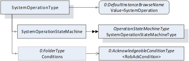
Figure 21 – SystemOperationType Overview
The SystemOperationType is formally defined in Table 42.
Table 42 – SystemOperationType Definition
|
Attribute |
Value |
||||
|
BrowseName |
SystemOperationType |
||||
|
IsAbstract |
False |
||||
|
References |
Node Class |
BrowseName |
DataType |
TypeDefinition |
Other |
|
Subtype of the BaseObjectType defined in OPC 10000-5. |
|||||
|
0:HasComponent |
Object |
SystemOperationStateMachine |
|
SystemOperationStateMachineType |
M |
|
0:HasComponent |
Object |
Conditions |
|
0:FolderType |
O |
|
0:HasProperty |
Variable |
0:DefaultInstanceBrowseName |
0:QualifiedName |
0:PropertyType |
|
|
ConformanceUnits |
|||||
|
Rob System Monitor |
|||||
|
Rob System Operation |
|||||
|
Rob RobAckCondInstance |
|||||
The Object SystemOperationStateMachine provides a state machine to monitor or command the controller at the system level. The SystemOperationStateMachineType is inherited from the OperationStateMachineType.
The folder Conditions (part of the ConformanceUnit RobAckCondInstance) provides instances of AcknowledgeableConditionType for the acknowledgement of single conditions or instances of MultiAcknowledgeableConditionType (see 8.1) for the acknowledgement of multiple conditions.
The Property 0:DefaultInstanceBrowseName of the SystemOperationType has an additional Attribute defined in
Table 44.
Table 43 – SystemOperationType additional subcomponents
|
BrowsePath |
References |
NodeClass |
BrowseName |
DataType |
TypeDefinition |
Others |
|
Conditions |
Organizes |
Object |
<AcknowledgeableCondition> |
|
AcknowledgeableConditionType |
MP |
Table 44 – SystemOperationType Attribute values for child Nodes
|
BrowsePath |
Value Attribute |
Description Attribute |
|
0:DefaultInstanceBrowseName |
SystemOperation |
|
The SystemOperationStateMachineType represents the behaviour of a controller at the system level and can be used for monitoring and for external or direct operation. In robot systems, a distinction is typically made between external and direct operation, depending on the OperationalMode (see 7.7.2).
If the system takes a significant amount of time to transition from the Idle State to the Ready State, the Idle State can be extended by the sub state machine IdleSubstateMachine. Alternatively, a vendor/application specific Substate machine may also be used.
For certain stop modes, the transition from the Executing State to the Ready State can take a significant amount of time. In such cases, the Executing State can be extended by the sub state machine ExecutingSubstateMachine. Alternatively, an application or vendor specific Substate machine may also be used.
The Substate machines enable the client to get more information during the transition.
The SystemMonitor Server Facet supports monitoring of the activities performed by the operator or system internally. (e.g. monitor condition changes and base causes) The SystemOperation Server Facet extends on the SystemMonitor Server Facet and adds support to operate the system.
The overview of the SystemOperationStateMachine with the IdleSubstateMachine as Substate machine of Idle State and the ExecutingSubstateMachine as Substate machine of Executing State with all transitions is shown in Figure 8.
The transitions in this state machine can occur due to internal processes of the system or they may be triggered by a method call. In case the transition is triggered by a method call, the transition might not occur immediately (e.g. it will be delayed until internal conditions are met).
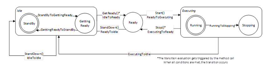
Figure 22 – SystemOperationStateMachine.
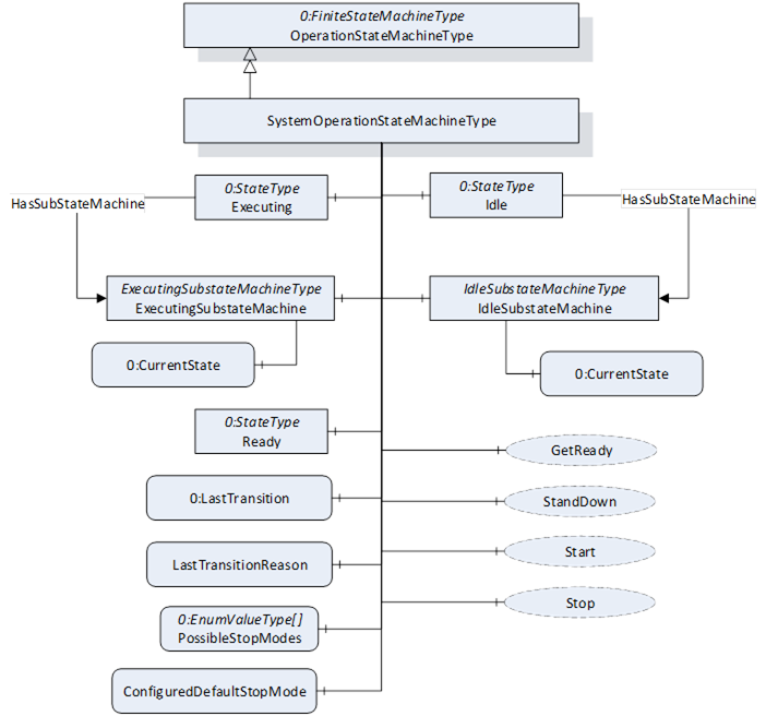
Figure 23 – SystemOperationStateMachineType.
The SystemOperationStateMachineType is formally defined in Table 45.
Table 45 – SystemOperationStateMachineType Definition
|
Attribute |
Value |
||||
|
BrowseName |
SystemOperationStateMachineType |
||||
|
IsAbstract |
False |
||||
|
References |
Node Class |
BrowseName |
DataType |
TypeDefinition |
Other |
|
Subtype of the OperationStateMachineType |
|||||
|
0:HasComponent |
Object |
IdleSubstateMachine |
|
IdleSubstateMachineType |
O |
|
0:HasComponent |
Object |
ExecutingSubstateMachine |
|
ExecutingSubstateMachineType |
O |
|
Inherited from OperationStateMachineType |
|||||
|
0:HasComponent |
Variable |
LastTransitionReason |
0:Int16 |
0:MultiStateValueDiscreteType |
M |
|
0:HasComponent |
Variable |
PossibleStopModes |
0:EnumValueType[] |
0:BaseDataVariableType |
O |
|
0:HasComponent |
Variable |
ConfiguredDefaultStopMode |
0:Int16 |
0:BaseDataVariableType |
O |
|
0:HasComponent |
Object |
Idle |
|
0:StateType |
|
|
0:HasComponent |
Object |
Ready |
|
0:StateType |
|
|
0:HasComponent |
Object |
Executing |
|
0:StateType |
|
|
0:HasComponent |
Object |
ReadyToIdle |
|
0:TransitionType |
|
|
0:HasComponent |
Object |
IdleToReady |
|
0:TransitionType |
|
|
0:HasComponent |
Object |
ExecutingToReady |
|
0:TransitionType |
|
|
0:HasComponent |
Object |
ReadyToExecuting |
|
0:TransitionType |
|
|
0:HasComponent |
Object |
ExecutingToIdle |
|
0:TransitionType |
|
|
0:HasComponent |
Object |
IdleToIdle |
|
0:TransitionType |
|
|
0:HasComponent |
Method |
Start |
|
|
O |
|
0:HasComponent |
Method |
Stop |
|
|
O |
|
0:HasComponent |
Method |
StandDown |
|
|
O |
|
0:HasComponent |
Method |
GetReady |
|
|
O |
|
0:HasComponent |
Variable |
LastTransition |
0:LocalizedText |
0:FiniteTransitionVariableType |
M |
|
0:GeneratesEvent |
ObjectType |
TransitionEventType |
|
|
O |
|
ConformanceUnits |
|||||
|
Rob System Monitor |
|||||
|
Rob System Operation |
|||||
|
Rob System Events |
|||||
|
Rob System Idle Substate |
|||||
|
Rob System ExecutingSubstate |
|||||
The Idle State of SystemOperationStatemachineType has additional subcomponents which are defined in Table 46
Table 46 – SystemOperationStateMachineType Additional Subcomponents
|
Source Path |
Reference |
Node Class |
BrowseName |
DataType |
TypeDefinition |
Other |
|
Idle |
0:HasSubStateMachine |
Object |
IdleSubstateMachine |
|
IdleSubstateMachineType |
O |
|
Executing |
0:HasSubStateMachine |
Object |
ExecutingSubstateMachine |
|
ExecutingSubstateMachineType |
O |
To acknowledge the state changes in a system the Conditions within the Conditions folder of SystemOperationType must be taken under consideration. A client might need to acknowledge them so that the robot system can be activated. (e.g. operational mode change requires acknowledgement to start the system)
Table 47 – SystemOperationStateMachineType State Descriptions
|
StateName |
Description |
|
Idle |
The system is available, but cannot be started because preparation is needed |
|
Ready |
The system is ready to start execution. |
|
Executing |
The system is executing. Typically, at least one task control is executing, however it is a system specific behaviour. |
Table 48 – SystemOperationStateMachine Transition Descriptions
|
TransitionName |
Description |
|
IdleToIdle |
Occurs in response to StandDown(), internal events, or when preparations to get the system ready are unsuccessful. |
|
IdleToReady |
Occurs in response to GetReady() or internal events, when preparations to get the system ready are successful. |
|
ReadyToIdle |
Occurs in response to StandDown() or internal events. |
|
ReadyToExecuting |
Occurs in response to Start() or internal events. |
|
ExecutingToReady |
Occurs in response to Stop() or internal events when the system has come to a stop |
|
ExecutingToIdle |
Occurs in response to internal events (typically in case of an error) |
The components of the SystemOperationStateMachineType have additional references which are defined in the table below.
Table 49 – SystemOperationStateMachineType Additional References
|
SourceBrowsePath |
Reference Type |
Is Forward |
TargetBrowsePath |
|
IdleToIdle |
0:FromState |
True |
Idle |
|
|
0:ToState |
True |
Idle |
0:HasCause |
True |
StandDown |
0:HasEffect |
True |
TransitionEventType |
|
IdleToReady |
0:FromState |
True |
Idle |
0:ToState |
True |
Ready |
0:HasCause |
True |
GetReady |
0:HasEffect |
True |
TransitionEventType |
|
ReadyToIdle |
0:FromState |
True |
Ready |
|
|
0:ToState |
True |
Idle |
|
|
0:HasCause |
True |
StandDown |
|
|
0:HasEffect |
True |
TransitionEventType |
|
ReadyToExecuting |
0:FromState |
True |
Ready |
0:ToState |
True |
Executing |
0:HasCause |
True |
Start |
0:HasEffect |
True |
TransitionEventType |
|
ExecutingToIdle |
0:FromState |
True |
Executing |
0:ToState |
True |
Idle |
0:HasEffect |
True |
TransitionEventType |
|
ExecutingToReady |
0:FromState |
True |
Executing |
0:ToState |
True |
Ready |
0:HasCause |
True |
Stop |
0:HasEffect |
True |
TransitionEventType |
The component Variables of the SystemOperationStateMachineType have additional Attributes defined in the table below.
Table 50 – SystemOperationStateMachineType Attribute values for child Nodes
|
BrowsePath |
Value Attribute |
||
|
1 |
||
|
2 |
||
|
3 |
||
|
1 |
||
|
2 |
||
|
3 |
||
|
4 |
||
|
5 |
||
|
6 |
The signature of this Method is specified below.
Signature
Start (
[out]0:Int32Status
);
The Start Method is called by a Client to start execution of the system that is represented by the state machine. If the method is successfully called, the method should return with a Good or Uncertain result code.
The Start Method allows an authorized Client to command the system to the Executing State.
Table 51 – Start Method Arguments
|
Argument |
Description |
|
Status |
0 – OK – Everything is OK 1 – E_SystemState – The system is not in correct state for this operation 2 – E_UnexpectedError – Unexpected Error during the Method call 3 – E_ActiveAlarm – An Active Alarm prevents the system start 4 – E_AcknowledgeRequired – Condition needs to be acknowledged <0 – shall be used for vendor-specific errors. >0 – are reserved for errors defined by this and future standards |
The possible Method result codes are formally defined in Table 52
Table 52 – Method Result Codes (defined in Call Service)
|
Result Code |
Description |
|
Good |
The system level operation succeeded |
|
Uncertain |
The value is uncertain. A concrete reason is defined in the Status Output-Argument. |
|
Bad_InternalError |
The Method could not be called due to an internal error |
|
Bad_ResourceUnavailable |
The Method is locked by another Client/Clientgroup |
|
Bad_UserAccessDenied |
The caller is not allowed to call this Method. |
The Start Method representation in the AddressSpace is formally defined in Table 53.
Table 53 – Start Method AddressSpace definition.
|
Attribute |
Value |
||||
|
BrowseName |
Start |
||||
|
References |
NodeClass |
BrowseName |
DataType |
TypeDefinition |
Others |
|
0:HasProperty |
Variable |
0:OutputArguments |
0:Argument[] |
0:PropertyType |
M |
|
|
|
|
|
|
|
|
ConformanceUnits |
|||||
|
Rob System Operation |
|||||
The signature of this Method is specified below.
Signature
Stop (
[in]0:Int64 StopMode
[out]0:Int32Status
);
The Stop Method allows an authorized Client to command the system to stop executing and leave the Executing state.
In conjunction with the usage of this method, the transient states can be expressed with Substate machines within the Executing state (e.g. the ExecutingSubstateMachine in 7.14)
The input argument StopMode must be either 0 or one of those listed in the PossibleStopModes Variable (see Table 31). If not, then a Bad_InvalidArgument Result Code is returned.
Table 54 – Stop Method Arguments
|
Argument |
Description |
|
StopMode |
must either be 0 or one of those listed in the PossibleStopModes Variable (see Table 31) |
|
Status |
0 – OK – Everything is OK 1 – E_SystemState – The system is not in correct state for this operation 2 – E_UnexpectedError – Unexpected Error during the Method call <0 – shall be used for vendor-specific errors. >0 – are reserved for errors defined by this and future standards |
The possible Method result codes are formally defined in Table 55
Table 55 – Method Result Codes (defined in Call Service)
|
Result Code |
Description |
|
Good |
The system level operation succeeded |
|
Bad_InternalError |
The system level operation failed because of an internal error |
|
Bad_ResourceUnavailable |
The Method is locked by another Client/Clientgroup |
|
Bad_UserAccessDenied |
The caller is not allowed to call this Method. |
|
Bad_InvalidArgument |
The input argument is invalid |
The Stop Method representation in the AddressSpace is formally defined in Table 56
Table 56 – Stop Method AddressSpace definition.
|
Attribute |
Value |
||||
|
BrowseName |
Stop |
||||
|
References |
NodeClass |
BrowseName |
DataType |
TypeDefinition |
Others |
|
0:HasProperty |
Variable |
0:InputArguments |
0:Argument[] |
0:PropertyType |
M |
|
0:HasProperty |
Variable |
0:OutputArguments |
0:Argument[] |
0:PropertyType |
M |
|
ConformanceUnits |
|||||
|
Rob System Operation |
|||||
The signature of this Method is specified below.
Signature
GetReady (
[out]0:Int32Status
);
The GetReady Method allows an authorized Client to request the system to transition from the Idle state to the Ready state. Internally the system prepares to get started in the next step (e.g. switching on the intermediate circuit). If the internal preparations for this transition are successful, the system will transition from Idle to Ready. If the internal preparations are unsuccessful then the IdleToIdle transition occurs.
In conjunction with the usage of this method, the transient states can be expressed with Substate machines within the Idle state (e.g. the IdleSubstateMachine in 7.13)
Table 57 – GetReady Method Arguments
|
Argument |
Description |
|
Status |
0 – OK – Everything is OK 1 – E_SystemState – The system is not in correct state for this operation 2 – E_UnexpectedError – Unexpected Error during the Method call 3 – E_ActiveAlarm – An Active Alarm prevents the system start 4 – E_AcknowledgeRequired – Condition needs to be acknowledged <0 – shall be used for vendor-specific errors. >0 – are reserved for errors defined by this and future standards |
The possible Method result codes are formally defined in Table 58
Table 58 – Method Result Codes (defined in Call Service)
|
Result Code |
Description |
|
Good |
The system level operation succeeded |
|
Bad_InternalError |
The system level operation failed because of an internal error |
|
Bad_ResourceUnavailable |
The Method is locked by another Client/Clientgroup |
|
Bad_UserAccessDenied |
The caller is not allowed to call this Method. |
The Start Method representation in the AddressSpace is formally defined in Table 59.
Table 59 – GetReady Method AddressSpace definition
|
Attribute |
Value |
||||
|
BrowseName |
GetReady |
||||
|
References |
NodeClass |
BrowseName |
DataType |
TypeDefinition |
Others |
|
0:HasProperty |
Variable |
0:OutputArguments |
0:Argument[] |
0:PropertyType |
M |
|
ConformanceUnits |
|||||
|
Rob System Operation |
|||||
The signature of this Method is specified below.
Signature
StandDown (
[out]0:Int32Status
);
The StandDown method allows an authorized Client to request the system to:
- transition from the Ready state to the Idle state or
- cancel an ongoing preparation of the system and causes the IdleToIdle transition.
Table 60 – StandDown Method Arguments
|
Argument |
Description |
|
Status |
0 – OK – Everything is OK 1 – E_SystemState – The system is not in correct state for this operation 2 – E_UnexpectedError – Unexpected Error during the Method call <0 – shall be used for vendor-specific errors. >0 – are reserved for errors defined by this and future standards |
In conjunction with the usage of this method, the transient states can be expressed with Substate machines within the Idle state (e.g. the IdleSubstateMachine in 7.13)
The possible Method result codes are formally defined in Table 61.
Table 61 – Method Result Codes (defined in Call Service)
|
Result Code |
Description |
|
Good |
The system level operation succeeded |
|
Bad_InternalError |
The system level operation failed because of an internal error |
|
Bad_ResourceUnavailable |
The Method is locked by another Client/Clientgroup |
|
Bad_UserAccessDenied |
The caller is not allowed to call this Method. |
The StandDown Method representation in the AddressSpace is formally defined in Table 62.
Table 62 – StandDown Method AddressSpace definition
|
Attribute |
Value |
||||
|
BrowseName |
StandDown |
||||
|
References |
NodeClass |
BrowseName |
DataType |
TypeDefinition |
ModellingRule |
|
0:HasProperty |
Variable |
0:OutputArguments |
0:Argument[] |
0:PropertyType |
M |
|
ConformanceUnits |
|||||
|
Rob System Operation |
|||||
The IdleSubstateMachineType, a Substate machine of the Idle State of the SystemOperationStateMachine, represents a mechanism to prepare a system in a way that it will reach Ready State of the SystemOperationStateMachine after preparation.
The overview of the IdleSubstateMachine with all transitions is shown in Figure 24.
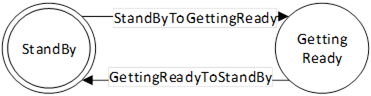
Figure 24 – IdleSubstateMachine
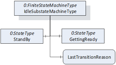
Figure 25 – IdleSubstateMachineType Overview
The IdleSubstateMachineType is formally defined in Table 63.
Table 63 – IdleSubstateMachineType Definition
|
Attribute |
Value |
||||
|
BrowseName |
IdleSubstateMachineType |
||||
|
IsAbstract |
False |
||||
|
References |
Node Class |
BrowseName |
DataType |
TypeDefinition |
Other |
|
Subtype of the FiniteStateMachineType defined in OPC 10000-5 |
|||||
|
0:HasComponent |
Variable |
LastTransitionReason |
0:Int16 |
0:MultiStateValueDiscreteType |
M |
|
0:HasComponent |
Object |
StandBy |
|
0:InitialStateType |
|
|
0:HasComponent |
Object |
GettingReady |
|
0:StateType |
|
|
0:HasComponent |
Object |
StandByToGettingReady |
|
0:TransitionType |
|
|
0:HasComponent |
Object |
GettingReadyToStandBy |
|
0:TransitionType |
|
|
0:HasComponent |
Variable |
LastTransition |
0:LocalizedText |
0:FiniteTransitionVariableType |
M |
|
0:GeneratesEvent |
ObjectType |
TransitionEventType |
|
|
O |
|
ConformanceUnits |
|||||
|
Rob System IdleSubstate |
|||||
|
Rob System Events |
|||||
The Variable LastTransitionReason provides the reason for the LastTransition. The EnumValue and ValueAsText of this 0:MultiStateValueDiscreteType are described in the table below.
Table 64 – IdleSubstateMachineType Attribute values for child nodes
|
BrowsePath |
Value Attribute |
Description Attribute |
||
|
[ {"Value":0,"DisplayName":"Unknown","Description":"Caused by an unknown reason"}, {"Value":1,"DisplayName":"External","Description":"Caused by external operation"}, {"Value":2,"DisplayName":"Direct","Description":"Caused by direct operation"}, {"Value":3,"DisplayName":"System","Description":"Caused by system specific behavior"}, {"Value":4,"DisplayName":"Error", "Description": "Caused by an error"}, {"Value":5,"DisplayName":"Application","Description":"Caused explicitly by end user program logic"} ] |
|
The states of the IdleSubstateMachineType are described in Table 65.
Table 65 – IdleSubstateMachineType State Descriptions
|
StateName |
Description |
|
StandBy |
The system is available, but cannot be started because a preparation is needed |
|
GettingReady |
The system was commanded to get ready (internally or via GoToReady() and the needed preparation to get ready is done in this state by the system. In the GettingReady state the system prepares what is to be done (e.g. switching on intermediate circuit) to be ready to start execution in a next step. Typically, all task controls which participate in system functionality are in in Ready (or Executing) state before calling the GoToReady() method on system level. When the preparation is done successfully the IdleSubstateMachine will be left and the Ready state of the SystemOperationStateMaschine will be entered. The ongoing preparation can be interrupted by calling the GoToStandBy Method. |
The transitions are described in .
Table 66 – IdleSubstateMachineType Transition Descriptions
|
TransitionName |
Description |
|
StandByToGettingReady |
Changes from StandBy to GettingReady because the preparation was initiated. |
|
GettingReadyToStandBy |
Changes from GettingReady to StandBy because the preparation was aborted. |
The components of the IdleSubstateMachineType have additional references which are defined in Table 67.
Table 67 – IdleSubstateMachineType Additional References
|
SourceBrowsePath |
Reference Type |
Is Forward |
TargetBrowsePath |
|
StandByToGettingReady |
0:FromState |
True |
StandBy |
0:ToState |
True |
GettingReady |
0:HasEffect |
True |
TransitionEventType |
|
GettingReadyToStandBy |
0:FromState |
True |
GettingReady |
0:ToState |
True |
StandBy |
0:HasEffect |
True |
TransitionEventType |
The component Variables of the IdleSubstateMachineType have additional Attributes defined in Table 68.
Table 68 – IdleSubstateMachineType Attribute values for child Nodes
|
BrowsePath |
Value Attribute |
||
|
1 |
||
|
2 |
||
|
1 |
||
|
2 |
The ExecutingSubstateMachineType, a Substate machine of Executing State of the SystemOperationStateMachine, represents a mechanism for describing the stopping behaviour of the system. This can be used to display the stopping behaviour in more detail depending on the StopMode commanded.
The overview of the ExecutingSubstateMachine with all transitions is shown in Figure 8.
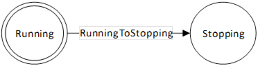
Figure 26 – ExecutingSubstateMachine
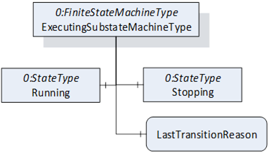
Figure 27 – ExecutingSubstateMachineType Overview
The ExecutingSubstateMachineType is formally defined in the table below.
Table 69 – ExecutingSubstateMachineType Definition
|
Attribute |
Value |
||||
|
BrowseName |
ExecutingSubstateMachineType |
||||
|
IsAbstract |
False |
||||
|
References |
Node Class |
BrowseName |
DataType |
TypeDefinition |
Other |
|
Subtype of the FiniteStateMachineType defined in OPC 10000-5 |
|||||
|
0:HasComponent |
Variable |
LastTransitionReason |
0:Int16 |
0:MultiStateValueDiscreteType |
M |
|
0:HasComponent |
Object |
Running |
|
0:InitialStateType |
|
|
0:HasComponent |
Object |
Stopping |
|
0:StateType |
|
|
0:HasComponent |
Object |
RunningToStopping |
|
0:TransitionType |
|
|
Inherited from FiniteStateMachineType |
|||||
|
0:HasComponent |
Variable |
LastTransition |
0:LocalizedText |
0:FiniteTransitionVariableType |
M |
|
0:GeneratesEvent |
ObjectType |
TransitionEventType |
|
|
O |
|
ConformanceUnits |
|||||
|
Rob System ExecutingSubstate |
|||||
|
Rob System Events |
|||||
The Variable LastTransitionReason provides the reason for the LastTransition. The EnumValues of this 0:MultiStateValueDiscreteType are described in Table 70.
Table 70 – ExecutingSubstateMachineType Attribute values for child nodes
|
BrowsePath |
Value Attribute |
Description Attribute |
||
|
[ {"Value":0,"DisplayName":"Unknown","Description":"Caused by an unknown reason"}, {"Value":1,"DisplayName":"External","Description":"Caused by external operation"}, {"Value":2,"DisplayName":"Direct","Description":"Caused by direct operation"}, {"Value":3,"DisplayName":"System","Description":"Caused by system specific behavior"}, {"Value":4,"DisplayName":"Error", "Description": "Caused by an error"}, {"Value":5,"DisplayName":"Application","Description":"Caused explicitly by end user program logic"} ] |
|
The states of the ExecutingSubstateMachineType are described in Table 71.
Table 71 – ExecutingSubstateMachineType State Descriptions
|
StateName |
Description |
|
Running |
The system is available, but cannot started because a preparation is needed |
|
Stopping |
The system was commanded to stop (internally or via Stop() and the needs some time for necessary background processes before entering the Ready state. |
The transitions are described in .
Table 72 – ExecutingSubstateMachineType Transition Descriptions
|
TransitionName |
Description |
|
RunningToStopping |
Changes from Running to Stopping because a system stop was initiated. |
The components of the ExecutingSubstateMachineType have additional references which are defined in the table below.
Table 73 – ExecutingSubstateMachineType Additional References
|
SourceBrowsePath |
Reference Type |
Is Forward |
TargetBrowsePath |
|
RunningToStopping |
0:FromState |
True |
Running |
0:ToState |
True |
Stopping |
0:HasEffect |
True |
TransitionEventType |
The component Variables of the IdleSubstateMachineType have additional Attributes defined in the table below.
Table 74 – ExecutingSubstateMachineType Attribute values for child Nodes
|
BrowsePath |
Value Attribute |
||
|
1 |
||
|
2 |
||
|
1 |
The TaskControlOperationType is an AddIn to extend instances of TaskControlType described in 7.21. It provides the possibility to handle programs with designated task controls. The task controls may be started manually or in a system context by use of SystemOperation.
The TaskControlOperationType provides a state machine to monitor or control a task control and information about which motion devices are controlled by this task control and is formally defined in Table 63.
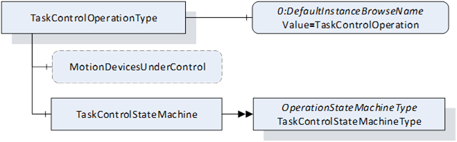
Figure 24 – TaskControlOperationType Overview
Table 63 – TaskControlOperationType Definition
|
Attribute |
Value |
||||
|
BrowseName |
TaskControlOperationType |
||||
|
IsAbstract |
False |
||||
|
References |
Node Class |
BrowseName |
DataType |
TypeDefinition |
Other |
|
Subtype of the BaseObjectType defined in OPC 10000-5. |
|||||
|
0:HasProperty |
Variable |
MotionDevicesUnderControl |
0:NodeId[] |
0:PropertyType |
O, RO |
|
0:HasComponent |
Object |
TaskControlStateMachine |
|
TaskControlStateMachineType |
M |
|
0:HasProperty |
Variable |
0:DefaultInstanceBrowseName |
0:QualifiedName |
0:PropertyType |
|
|
ConformanceUnits |
|||||
|
Rob Task Control Monitor |
|||||
|
Rob Task Control Operation |
|||||
|
Rob TC MD Relationship |
|||||
The optional Variable MotionDevicesUnderControl provides an array of NodeIds pointing to instances of MotionDeviceType described in 7.2, which are under control of this task control, in combination with the loaded program.
The Property 0:DefaultInstanceBrowseName of the TaskControlOperationType has an additional Attribute defined in Table 64.
Table 64 – TaskControlOperationType Attribute values for child Nodes
|
BrowsePath |
Value Attribute |
Description Attribute |
|
0:DefaultInstanceBrowseName |
TaskControlOperation |
|
The TaskControlStateMachineType represents the behaviour of a task control and can be used for monitoring or for remote control.
To provide information about the condition of a program loaded inside a task control and the possibility to reset the loaded program the Ready State can be extended by the ReadySubstateMachineType.
The Task Control Monitor ConformanceUnit supports monitoring of the activities done by the operator or system internally. The Task Control Operation ConformanceUnit supports additional operations by Methods.
The overview of the state machine with all transitions is shown in
When the state machine changes from Executing State to Ready State caused by internal behaviour of the task control (e.g. because program is ended) it is expected that the task control can be started immediately again e.g. by the Start() method. So, the application may set the loaded program to its entry point (like the ResetToProgramStart() Method) while transition ExecutingToReady or when the Start() Method is called, that no additional reset of the program is needed.
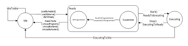
Figure 29 – TaskControl State Machine with ReadySubstateMachine in Ready State
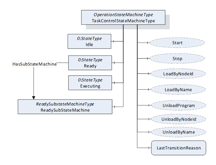
Figure 30 – TaskControlStateMachineType with the ReadySubstateMachine
The TaskControlStateMachineType is formally defined in Table 65.
Table 65 – TaskControlStateMachineType Definition
|
Attribute |
Value |
||||
|
BrowseName |
TaskControlStateMachineType |
||||
|
IsAbstract |
False |
||||
|
References |
Node Class |
BrowseName |
DataType |
TypeDefinition |
Other |
|
|
|
|
|
|
|
|
Subtype of the OperationStateMachineType |
|||||
|
|
|||||
|
0:HasComponent |
Object |
ReadySubstateMachine |
|
ReadySubstateMachineType |
O |
|
0:HasComponent |
Method |
LoadByNodeId |
|
|
O |
|
0:HasComponent |
Method |
LoadByName |
|
|
O |
|
0:HasComponent |
Method |
UnloadProgram |
|
|
O |
|
0:HasComponent |
Method |
UnloadByNodeId |
|
|
O |
|
0:HasComponent |
Method |
UnloadByName |
|
|
O |
|
Inherited from OperationStateMachineType |
|||||
|
0:HasComponent |
Variable |
LastTransitionReason |
0:Int16 |
0:MultiStateValueDiscreteType |
M |
|
0:HasComponent |
Variable |
PossibleStopModes |
0:EnumValueType[] |
0:BaseDataVariableType |
O |
|
0:HasComponent |
Variable |
ConfiguredDefaultStopMode |
0:Int16 |
0:BaseDataVariableType |
O |
|
|
|
|
|
|
|
|
0:HasComponent |
Object |
Idle |
|
0:StateType |
|
|
0:HasComponent |
Object |
Ready |
|
0:StateType |
|
|
0:HasComponent |
Object |
Executing |
|
0:StateType |
|
|
0:HasComponent |
Object |
IdleToIdle |
|
0:TransitionType |
|
|
0:HasComponent |
Object |
ReadyToIdle |
|
0:TransitionType |
|
|
0:HasComponent |
Object |
IdleToReady |
|
0:TransitionType |
|
|
0:HasComponent |
Object |
ExecutingToReady |
|
0:TransitionType |
|
|
0:HasComponent |
Object |
ReadyToExecuting |
|
0:TransitionType |
|
|
0:HasComponent |
Object |
ExecutingToIdle |
|
0:TransitionType |
|
|
0:HasComponent |
Method |
Start |
|
|
O |
|
0:HasComponent |
Method |
Stop |
|
|
O |
|
0:HasComponent |
Variable |
LastTransition |
0:LocalizedText |
0:FiniteTransitionVariableType |
M |
|
0:GeneratesEvent |
ObjectType |
TransitionEventType |
|
|
O |
|
ConformanceUnits |
|||||
|
Rob Task Control Monitor |
|||||
|
Rob Task Control Operation |
|||||
|
Rob Task Control ReadySubstate |
|||||
|
Rob System Events |
|||||
The Ready State of TaskControlStateMachineType has additional subcomponents which are defined in Table 66.
Table 66 – TaskControlStateMachineType Additional Subcomponents
|
Source Path |
Reference |
NodeClass |
BrowseName |
DataType |
TypeDefinition |
Others |
|
Ready |
0:HasSubStateMachine |
Object |
ReadySubstateMachine |
|
ReadySubstateMachineType |
O |
The states of the TaskControlStateMachineType are described in Table 67.
Table 67 – TaskControlStateMachineType State Descriptions
|
StateName |
Description |
|
Idle |
The task control is not loaded with a program. |
|
Ready |
The task control is loaded with a program and is not executing the program. |
|
Executing |
The task control is loaded with a program and is executing the program. If the task control automatically starts the program at the beginning, after reaching the end, it shall stay in Executing state (continuously executing). |
The transitions are described in the table below.
Table 68 – TaskControlStateMachineType Transition Descriptions
|
TransitionName |
Description |
|
IdleToIdle |
Occurs if the program could not be loaded correctly. |
|
IdleToReady |
Occurs in response to LoadProgram() or internal events, when loading a program to the task control. |
|
ReadyToIdle |
Occurs in response to UnloadProgram() or internal events, when unloading a program from the task control. |
|
ReadyToExecuting |
Occurs in response to Start() or internal events, when starting a loaded program in the task control. |
|
ExecutingToReady |
Occurs in response to Stop() or internal events, when stopping a loaded program in the task control. |
|
ExecutingToIdle |
Occurs in response to internal events, when stopping a loaded program in the task control and unloading the task control. |
The components of the TaskControlStateMachineType have additional references which are defined in Table 69.
Table 69 – TaskControlStateMachineType Additional References
|
SourceBrowsePath |
Reference Type |
Is Forward |
TargetBrowsePath |
|
IdleToIdle |
0:FromState |
True |
Idle |
0:ToState |
True |
Idle |
0:HasEffect |
True |
TransitionEventType |
|
IdleToReady |
0:FromState |
True |
Idle |
0:ToState |
True |
Ready |
0:HasCause |
True |
LoadByNodeId |
0:HasCause |
True |
LoadByName |
0:HasEffect |
True |
TransitionEventType |
|
ReadyToIdle |
0:FromState |
True |
Ready |
0:ToState |
True |
Idle |
0:HasCause |
True |
UnloadProgram |
0:HasCause |
True |
UnloadByNodeId |
0:HasCause |
True |
UnloadByName |
0:HasEffect |
True |
TransitionEventType |
|
ReadyToExecuting |
0:FromState |
True |
Ready |
0:ToState |
True |
Executing |
0:HasCause |
True |
Start |
0:HasEffect |
True |
TransitionEventType |
|
ExecutingToReady |
0:FromState |
True |
Executing |
0:ToState |
True |
Ready |
0:HasCause |
True |
Stop |
0:HasEffect |
True |
TransitionEventType |
|
ExecutingToIdle |
0:FromState |
True |
Executing |
0:ToState |
True |
Idle |
0:HasEffect |
True |
TransitionEventType |
The component Variables of the TaskControlStateMachineType have additional Attributes defined in Table 70.
Table 70 – TaskControlStateMachineType Attribute values for child Nodes
|
BrowsePath |
Value Attribute |
||
|
1 |
||
|
2 |
||
|
3 |
||
|
1 |
||
|
2 |
||
|
3 |
||
|
4 |
||
|
5 |
||
|
6 |
The signature of this Method is specified below.
Signature
LoadByNodeId (
[in]0:ExpandedNodeId Id
[out]0:Int32 Status
);
Table 71 specifies the Arguments.
Table 71 – LoadByNodeId Method Arguments
|
Argument |
Description |
|
Id |
ExpandedNodeId pointing to an instance of FileType representing a task control program or module |
|
Status |
0 – OK – Everything is OK 1 – E_SystemState – The system is not in correct state for this operation 2 – E_UnexpectedError – Unexpected Error during the method call 3 – E_ActiveAlarm – An Active Alarm prevents the system start 4 – E_AcknowledgeRequired – Condition needs to be acknowledged <0 – shall be used for vendor-specific errors. >0 – are reserved for errors defined by this and future standards |
The LoadByNodeId Method is called by a Client to load a program or a module into a task control.
For the storage of programs, the Server may support the Programs folder defined within the ControllerType. (see 7.18). This method can be used to load the program or module into the Task Control if the program or module itself is available in the address space (e.g. within the Programs folder). The Id input argument shall be used to identify the program in the address space. This method can be a synchronous or an asynchronous method. In case it is a synchronous method, the return output arguments may contain more information about the Success or Failure of the method call. If the system is in the Idle state when the method is called, and something goes wrong internally then instead of the IdleToReady transition, the IdleToIdle transition shall be observed by the client. If the system is already in the Ready state and the LoadByNodeId is called and fails, it is system dependent, whether the system goes back to the Idle state or remains in the Ready state. Calling LoadByNodeId in the Executing state will fail in normal circumstances.
The possible Method result codes are formally defined in Table 72. Some of these StatusCodes correspond to the ProgramId input argument.
Clients may inspect the Status output argument to determine if the program was successfully loaded or if it failed.
Table 72 – Method Result Codes (defined in Call Service)
|
Result Code |
Description |
|
Good |
The task control operation succeeded |
|
Bad_InternalError |
The task control operation failed because of an internal error |
|
Bad_ResourceUnavailable |
The Method is locked by another Client/Clientgroup |
|
Bad_UserAccessDenied |
The caller is not allowed to call this Method. |
|
Bad_NodeIdUnknown |
|
|
Bad_NodeIdInvalid |
The syntax of the NodeId is not valid. |
The LoadByNodeId Method representation in the AddressSpace is formally defined in Table 73.
Table 73 – LoadByNodeId Method AddressSpace definition
|
Attribute |
Value |
||||
|
BrowseName |
LoadByNodeId |
||||
|
References |
NodeClass |
BrowseName |
DataType |
TypeDefinition |
ModellingRule |
|
0:HasProperty |
Variable |
0:InputArguments |
0:Argument[] |
0:PropertyType |
M |
|
0:HasProperty |
Variable |
0:OutputArguments |
0:Argument[] |
0:PropertyType |
M |
|
ConformanceUnits |
|||||
|
Rob Task Control Operation |
|||||
The signature of this Method is specified below.
Signature
LoadByName (
[in]0:StringName
[out]0:Int32Status
);
The table below specifies the Arguments.
Table 74 – LoadByName Method Arguments
|
Argument |
Description |
|
Name |
Name to identify a task control program or module |
|
Status |
0 – OK – Everything is OK 1 – E_SystemState – The system is not in correct state for this operation 2 – E_UnexpectedError – Unexpected Error during the method call 3 – E_ActiveAlarm – An Active Alarm prevents the system start 4 – E_AcknowledgeRequired – Condition needs to be acknowledged <0 – shall be used for vendor-specific errors. >0 – are reserved for errors defined by this and future standards |
The LoadByName Method is called by a Client to load a program or module to a task control. The controller uses the Name input argument to identify the program or module to load into the task control. The behaviour of this method is identical to the LoadByNodeId (see 7.16.2).
The possible Method result codes are formally defined in the table below. Some of these StatusCodes correspond to the Name input argument.
Clients may inspect the Status output argument to determine if the program was successfully loaded or if it failed.
Table 75 – Method Result Codes (defined in Call Service)
|
Result Code |
Description |
|
Good |
The task control operation succeeded |
|
Bad_InternalError |
The task control operation failed because of an internal error |
|
Bad_ResourceUnavailable |
The Method is locked by another Client/Clientgroup |
|
Bad_UserAccessDenied |
The caller is not allowed to call this Method. |
The LoadByName Method representation in the AddressSpace is formally defined in the table below.
Table 76 – LoadByName Method AddressSpace definition
|
Attribute |
Value |
||||
|
BrowseName |
LoadByName |
||||
|
References |
NodeClass |
BrowseName |
DataType |
TypeDefinition |
ModellingRule |
|
0:HasProperty |
Variable |
0:InputArguments |
0:Argument[] |
0:PropertyType |
0:Mandatory |
|
0:HasProperty |
Variable |
0:OutputArguments |
0:Argument[] |
0:PropertyType |
0:Mandatory |
|
ConformanceUnits |
|||||
|
Rob Task Control Operation |
|||||
The signature of this Method is specified below.
Signature
UnloadProgram (
[out]0:Int32 Status
);
The table below specifies the Arguments.
Table 77 – UnloadProgram Method Arguments
|
Argument |
Description |
|
Status |
0 – OK – Everything is OK 1 – E_SystemState – The system is not in correct state for this operation 2 – E_UnexpectedError – Unexpected Error during the method call 3 – E_ActiveAlarm – An Active Alarm prevents the system start 4 – E_AcknowledgeRequired – Condition needs to be acknowledged <0 – shall be used for vendor-specific errors. >0 – are reserved for errors defined by this and future standards |
The UnloadProgram Method is called by a Client to unload the program from a task control.
The possible Method result codes are formally defined in the table below.
Table 78 – Method Result Codes (defined in Call Service)
|
Result Code |
Description |
|
Good |
The task control operation succeeded |
|
Bad_InternalError |
The task control operation failed because of an internal error |
|
Bad_ResourceUnavailable |
The Method is locked by another Client/Clientgroup |
|
Bad_UserAccessDenied |
The caller is not allowed to call this Method. |
The UnloadProgram Method representation in the AddressSpace is formally defined in the table below.
Table 79 – UnloadProgram Method AddressSpace definition
|
Attribute |
Value |
||||
|
BrowseName |
UnloadProgram |
||||
|
References |
NodeClass |
BrowseName |
DataType |
TypeDefinition |
ModellingRule |
|
0:HasProperty |
Variable |
0:OutputArguments |
0:Argument[] |
0:PropertyType |
0:Mandatory |
|
ConformanceUnits |
|||||
|
Rob Task Control Operation |
|||||
The signature of this Method is specified below.
Signature
UnloadByNodeId (
[in] 0:ExpandedNodeId Id
[out]0:Int32 Status
);
Table 80 specifies the Arguments.
Table 80 – UnloadByNodeId Method Arguments
|
Argument |
Description |
|
Id |
Expanded NodeId of the module to be unloaded |
|
Status |
0 – OK – Everything is OK 1 – E_SystemState – The system is not in correct state for this operation 2 – E_UnexpectedError – Unexpected Error during the method call 3 – E_ActiveAlarm – An Active Alarm prevents the system start 4 – E_AcknowledgeRequired – Condition needs to be acknowledged <0 – shall be used for vendor-specific errors. >0 – are reserved for errors defined by this and future standards |
The UnloadByNodeId Method is called by a Client to unload a task module from a task control. This only works if the task modules are expressed in the address space (7.22).
The possible Method result codes are formally defined in the table below.
Table 81 – Method Result Codes (defined in Call Service)
|
Result Code |
Description |
|
Good |
The task control operation succeeded |
|
Bad_InternalError |
The task control operation failed because of an internal error |
|
Bad_ResourceUnavailable |
The Method is locked by another Client/Clientgroup |
|
Bad_UserAccessDenied |
The caller is not allowed to call this Method. |
The UnloadByNodeId Method representation in the AddressSpace is formally defined in Table 82. This method might not always result in a state change from Ready to Idle.
Table 82 – UnloadByNodeId Method AddressSpace definition
|
Attribute |
Value |
||||
|
BrowseName |
UnloadByNodeId |
||||
|
References |
NodeClass |
BrowseName |
DataType |
TypeDefinition |
ModellingRule |
|
0:HasProperty |
Variable |
0:InputArguments |
0:Argument[] |
0:PropertyType |
0:Mandatory |
|
0:HasProperty |
Variable |
0:OutputArguments |
0:Argument[] |
0:PropertyType |
0:Mandatory |
|
ConformanceUnits |
|||||
|
Rob Task Control Operation |
|||||
The signature of this Method is specified below.
Signature
UnloadByName (
[in] 0:String Name
[out]0:Int32 Status
);
Table 83 specifies the Arguments.
Table 83 – UnloadByName Method Arguments
|
Argument |
Description |
|
Name |
Name of the module to be unloaded |
|
Status |
0 – OK – Everything is OK 1 – E_SystemState – The system is not in correct state for this operation 2 – E_UnexpectedError – Unexpected Error during the method call 3 – E_ActiveAlarm – An Active Alarm prevents the system start 4 – E_AcknowledgeRequired – Condition needs to be acknowledged <0 – shall be used for vendor-specific errors. >0 – are reserved for errors defined by this and future standards |
The UnloadByName Method is called by a Client to unload a module from a task control. This can be used to unload the task modules if they are not expressed in the address space and internal logic is used to find the module to be unloaded based on the Name input argument.
This method might not always result in a state change from Ready to Idle.
The possible Method result codes are formally defined in the table below.
Table 84 – Method Result Codes (defined in Call Service)
|
Result Code |
Description |
|
Good |
The task control operation succeeded |
|
Bad_InternalError |
The task control operation failed because of an internal error |
|
Bad_ResourceUnavailable |
The Method is locked by another Client/Clientgroup |
|
Bad_UserAccessDenied |
The caller is not allowed to call this Method. |
The UnloadByName Method representation in the AddressSpace is formally defined in the table below.
Table 85 – UnloadByName Method AddressSpace definition
|
Attribute |
Value |
||||
|
BrowseName |
UnloadByName |
||||
|
References |
NodeClass |
BrowseName |
DataType |
TypeDefinition |
ModellingRule |
|
0:HasProperty |
Variable |
0:InputArguments |
0:Argument[] |
0:PropertyType |
0:Mandatory |
|
0:HasProperty |
Variable |
0:OutputArguments |
0:Argument[] |
0:PropertyType |
0:Mandatory |
|
ConformanceUnits |
|||||
|
Rob Task Control Operation |
|||||
The signature of this Method is specified below.
Signature
Start (
[out]0:Int32Status
);
Table 86 specifies the Arguments.
Table 86 – Start Method Arguments
|
Argument |
Description |
|
Status |
0 – OK – Everything is OK 1 – E_SystemState – The system is not in correct state for this operation 2 – E_UnexpectedError – Unexpected Error during the method call 3 – E_ActiveAlarm – An Active Alarm prevents the system start 4 – E_AcknowledgeRequired – Condition needs to be acknowledged <0 – shall be used for vendor-specific errors. >0 – are reserved for errors defined by this and future standards |
The Start method can only be successfully called when the task control is in the Ready state. Depending on the program pointer, the system shall attempt to start executing from the beginning of the program or continue executing from where it was suspended (see Substate machine description of this state in 7.17).
The possible Method result codes are formally defined in Table 87.
Table 87 - Method Result Codes (defined in Call Service)
|
Result Code |
Description |
|
Good |
The task control operation succeeded |
|
Bad_InternalError |
The task control operation failed because of an internal error |
|
Bad_ResourceUnavailable |
The Method is locked by another Client/Clientgroup |
|
Bad_UserAccessDenied |
The caller is not allowed to call this Method. |
The Start Method representation in the AddressSpace is formally defined in Table 88.
Table 88 – Start Method AddressSpace definition.
|
Attribute |
Value |
||||
|
BrowseName |
Start |
||||
|
References |
NodeClass |
BrowseName |
DataType |
TypeDefinition |
Others |
|
0:HasProperty |
Variable |
0:OutputArguments |
0:Argument[] |
0:PropertyType |
M |
|
ConformanceUnits |
|||||
|
Rob Task Control Operation |
|||||
The signature of this Method is specified below.
Signature
Stop (
[in]0:Int64 StopMode
[out]0:Int32Status
);
Table 89 specifies the Arguments.
Table 89 – StopMethod Arguments
|
Argument |
Description |
|
StopMode |
must either be 0 or one of those listed in the PossibleStopModes Variable (see Table 31) |
|
Status |
0 – OK – Everything is OK 1 – E_SystemState – The system is not in correct state for this operation 2 – E_UnexpectedError – Unexpected Error during the method call 3 – E_ActiveAlarm – An Active Alarm prevents the system start 4 – E_AcknowledgeRequired – Condition needs to be acknowledged <0 – shall be used for vendor-specific errors. >0 – are reserved for errors defined by this and future standards |
The Stop Method allows an authorized Client to command the task control to stop executing and leave the Executing state and go to the Ready state. If the ReadySubstateMachine (see 7.17) is present, the task control shall be in the Suspended state of the Substate machine.
The input argument StopMode must be either 0 or one of those listed in the PossibleStopModes Variable (see Section). If not, then a Bad_InvalidArgument Result Code is returned.
The possible Method result codes are formally defined in the table below.
Table 90 – Method Result Codes (defined in Call Service)
|
Result Code |
Description |
|
Good |
The task control operation succeeded |
|
Bad_InternalError |
The task control operation failed because of an internal error |
|
Bad_ResourceUnavailable |
The Method is locked by another Client/Clientgroup |
|
Bad_UserAccessDenied |
The caller is not allowed to call this Method. |
The Stop Method representation in the AddressSpace is formally defined in Table 91.
Table 91 – Stop Method AddressSpace definition.
|
Attribute |
Value |
||||
|
BrowseName |
Stop |
||||
|
References |
NodeClass |
BrowseName |
DataType |
TypeDefinition |
ModellingRule |
|
0:HasProperty |
Variable |
0:InputArguments |
0:Argument[] |
0:PropertyType |
0:Mandatory |
|
0:HasProperty |
Variable |
0:OutputArguments |
0:Argument[] |
0:PropertyType |
0:Mandatory |
|
ConformanceUnits |
|||||
|
Rob Task Control Operation |
|||||
The ReadySubstateMachineType represents the condition of a program loaded into a task control (TaskControlStateMachine is in Ready State). The state machine has two states to distinguish whether the program pointer is at an initial program position (AtProgramStart) or anywhere else in the program (Suspended). It provides the information whether the program pointer is at the start or in the middle of the program. The method ResetToProgramStart can be used to set the program pointer to the start of the program. The state after entering this state machine depends on the program pointer position.
The TaskControlReadyMonitor ConformanceUnit defines monitoring of the ReadySubstateMachine. The TaskControlReadyReinitalize ConformanceUnit defines additionally the reinitialization of the program by a method.
The overview of the state machine with all transitions is shown in .
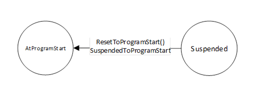
Figure 31 – ReadySubstateMachine
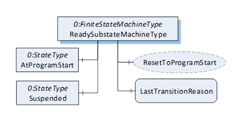
Figure 32 – ReadySubstateMachineType Overview
The ReadySubstateMachineType is formally defined in Table 104.
Table 104 – ReadySubstateMachineType Definition
|
Attribute |
Value |
||||
|
BrowseName |
ReadySubstateMachineType |
||||
|
IsAbstract |
False |
||||
|
References |
Node Class |
BrowseName |
DataType |
TypeDefinition |
Other |
|
Subtype of the FiniteStateMachineType defined in OPC 1000-5 |
|||||
|
0:HasComponent |
Variable |
LastTransitionReason |
0:Int16 |
0:MultiStateValueDiscreteType |
M |
|
0:HasComponent |
Object |
AtProgramStart |
|
0:StateType |
|
|
0:HasComponent |
Object |
Suspended |
|
0:StateType |
|
|
0:HasComponent |
Object |
ProgramStartToSuspended |
|
0:TransitionType |
|
|
0:HasComponent |
Object |
SuspendedToProgramStart |
|
0:TransitionType |
|
|
0:HasComponent |
Method |
ResetToProgramStart |
|
|
O |
|
Inherited from FiniteStateMachineType |
|||||
|
0:HasComponent |
Variable |
LastTransition |
0:LocalizedText |
0:FiniteTransitionVariableType |
M |
|
0:GeneratesEvent |
ObjectType |
TransitionEventType |
|
|
O |
|
ConformanceUnits |
|||||
|
Rob Task Control ReadySubstate |
|||||
|
Rob Task Control Ready Reset |
|||||
The Variable LastTransitionReason provides the reason for the LastTransition. The EnumValue and ValueAsText of this 0:MultiStateValueDiscreteType are described in .
Table 105 – ReadySubstateMachineType Attribute values for child nodes
|
BrowsePath |
Value Attribute |
Description Attribute |
||
|
[ {"Value":0,"DisplayName":"Unknown","Description":"Caused by an unknown reason"}, {"Value":1,"DisplayName":"External","Description":"Caused by external operation"}, {"Value":2,"DisplayName":"Direct","Description":"Caused by direct operation"}, {"Value":3,"DisplayName":"System","Description":"Caused by system specific behavior"}, {"Value":4,"DisplayName":"Error", "Description": "Caused by an error"}, {"Value":5,"DisplayName":"Application","Description":"Caused explicitly by end user program logic"} ] |
|
The states of the ReadySubstateMachineType are described in Table 106.
Table 106 – ReadySubstateMachineType State Descriptions
|
StateName |
Description |
|
AtProgramStart |
The program pointer of the program loaded in the task control is at the starting point. |
|
Suspended |
The program pointer of the program loaded in the task control is anywhere in the program, but not at starting point. |
The components of the ReadySubstateMachineType have additional references which are defined in Table 107.
Table 107 – ReadySubstateMachineType Additional References
|
SourceBrowsePath |
Reference Type |
Is Forward |
TargetBrowsePath |
|
ProgramStartToSuspended |
0:FromState |
True |
AtProgramStart |
0:ToState |
True |
Suspended |
0:HasEffect |
True |
TransitionEventType |
|
SuspendedToProgramStart |
0:FromState |
True |
Suspended |
0:ToState |
True |
AtProgramStart |
0:HasEffect |
True |
TransitionEventType |
0:HasCause |
True |
ResetToProgramStart |
The transitions are described in Table 108 – ReadySubstateMachineType Transition Descriptions.
Table 108 – ReadySubstateMachineType Transition Descriptions
|
TransitionName |
Description |
|
ProgramStartToSuspended |
Changes from AtProgramStart to Suspended. |
|
SuspendedToProgramStart |
Changes from Suspended to AtProgramStart because program was restarted. (Direct, External, System) |
The component Variables of the ReadySubstateMachineType have additional Attributes defined in Table 109.
Table 109 – ReadySubstateMachineType Attribute values for child Nodes
|
BrowsePath |
Value Attribute |
||
|
1 |
||
|
2 |
||
|
1 |
||
|
2 |
The signature of this Method is specified below.
Signature
ResetToProgramStart (
[out]0:Int32Status
);
Table 92 specifies the Arguments.
Table 92 – ResetToProgramStart Method Arguments
|
Argument |
Description |
|
Status |
0 – OK – Everything is OK 1 – E_SystemState – The system is not in correct state for this operation 2 – E_UnexpectedError – Unexpected Error during the method call 3 – E_ActiveAlarm – An Active Alarm prevents the system start 4 – E_AcknowledgeRequired – Condition needs to be acknowledged <0 – shall be used for vendor-specific errors. >0 – are reserved for errors defined by this and future standards |
The ResetToProgramStart Method is called by a Client to set the program pointer to the starting point of the program.
The possible Method result codes are formally defined in the table below.
Table 93 – Method Result Codes (defined in Call Service)
|
Result Code |
Description |
|
Good |
The operation succeeded |
|
Bad_InternalError |
The operation failed because of an internal error |
|
Bad_ResourceUnavailable |
The Method is locked by another Client/Clientgroup |
|
Bad_UserAccessDenied |
The caller is not allowed to call this Method. |
The ResetToProgramStart Method representation in the AddressSpace is formally defined in Table 94.
Table 94 – ResetToProgramStart Method AddressSpace definition
|
Attribute |
Value |
||||
|
BrowseName |
ResetToProgramStart |
||||
|
References |
NodeClass |
BrowseName |
DataType |
TypeDefinition |
ModellingRule |
|
0:HasProperty |
Variable |
0:OutputArguments |
0:Argument[] |
0:PropertyType |
M |
|
ConformanceUnits |
|||||
|
Task Control Ready Reset |
|||||
The ControllerType describes the control unit of motion devices. One motion device system can have one or more instances of the ControllerType. The ControllerType is formally defined in Table 95.
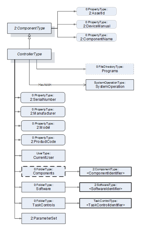
Figure 25 – Overview ControllerType
Table 95 – ControllerType Definition
|
Attribute |
Value |
||||
|
BrowseName |
ControllerType |
||||
|
IsAbstract |
False |
||||
|
References |
Node Class |
BrowseName |
DataType |
TypeDefinition |
Modelling Rule |
|
Subtype of the ComponentType defined in OPC Unified Architecture for Devices (DI) |
|||||
|
0:HasProperty |
Variable |
2:SerialNumber |
0:String |
0:PropertyType |
M |
|
0:HasProperty |
Variable |
2:Manufacturer |
0:LocalizedText |
0:PropertyType |
M |
|
0:HasProperty |
Variable |
2:Model |
0:LocalizedText |
0:PropertyType |
M |
|
0:HasProperty |
Variable |
2:ProductCode |
0:String |
0:PropertyType |
M |
|
0:HasComponent |
Object |
CurrentUser |
|
UserType |
M |
|
0:HasComponent |
Object |
Components |
|
0:FolderType |
O |
|
0:HasComponent |
Object |
Software |
|
0:FolderType |
M |
|
0:HasComponent |
Object |
TaskControls |
|
0:FolderType |
M |
|
0:HasComponent |
Object |
2:ParameterSet |
|
0:BaseObjectType |
O |
|
HasSafetyStates |
Object |
<SafetyStatesIdentifier> |
|
SafetyStateType |
OP |
|
0:HasComponent |
Object |
Programs |
|
0:FileDirectoryType |
O |
|
0:HasAddIn |
Object |
SystemOperation |
|
SystemOperationType |
O |
|
Controls |
Object |
<MotionDeviceIdentifier> |
|
MotionDeviceType |
OP |
|
0:HasProperty |
Variable |
2:AssetId |
0:String |
0:PropertyType |
O |
|
0:HasProperty |
Variable |
2:DeviceManual |
0:String |
0:PropertyType |
O |
|
0:HasProperty |
Variable |
2:ComponentName |
0:LocalizedText |
0:PropertyType |
O |
|
Conformance Units |
|||||
|
Rob System Monitor |
|||||
|
Rob System Operation |
|||||
|
Rob Program File Directory |
|||||
|
Rob System Events |
|||||
|
Rob Controller AM Extended |
|||||
|
Rob Controller AM Extended |
|||||
|
Rob MotionDeviceSystem Base |
|||||
The components of the ControllerType have additional subcomponents which are defined in Table 96.
Table 96 – ControllerType Additional Subcomponents
|
Source Path |
Reference |
NodeClass |
BrowseName |
DataType |
TypeDefinition |
Others |
|
Components |
0:HasComponent |
Object |
<ComponentIdentifier> |
|
2:ComponentType |
MP |
|
Software |
0:HasComponent |
Object |
<SoftwareIdentifier> |
|
2:SoftwareType |
MP |
|
TaskControls |
0:HasComponent |
Object |
<TaskControlIdentifier> |
|
TaskControlType |
MP |
|
2:ParameterSet |
0:HasComponent |
Variable |
TotalPowerOnTime |
0:DurationString |
0:BaseDataVariableType |
O |
|
2:ParameterSet |
0:HasComponent |
Variable |
StartUpTime |
0:DateTime |
0:BaseDataVariableType |
O |
|
2:ParameterSet |
0:HasComponent |
Variable |
UpsState |
0:String |
0:BaseDataVariableType |
O |
|
2:ParameterSet |
0:HasComponent |
Variable |
TotalEnergyConsumption |
0:Double |
0:AnalogUnitType |
O |
|
2:ParameterSet |
0:HasComponent |
Variable |
CabinetFanSpeed |
0:Double |
0:AnalogUnitType |
O |
|
2:ParameterSet |
0:HasComponent |
Variable |
CPUFanSpeed |
0:Double |
0:AnalogUnitType |
O |
|
2:ParameterSet |
0:HasComponent |
Variable |
InputVoltage |
0:Double |
0:AnalogUnitType |
O |
|
2:ParameterSet |
0:HasComponent |
Variable |
Temperature |
0:Double |
0:AnalogUnitType |
O |
The SerialNumber property is a unique production number assigned by the manufacturer of the device. This is often stamped on the outside of the device and may be used for traceability and warranty purposes. This property is derived from ComponentType defined in OPC 10000-100.
The Manufacturer property provides the name of the company that manufactured the device. This property is derived from ComponentType defined in OPC 10000-100.
The Model property provides the name of the product. This property is derived from ComponentType defined in OPC 10000-100.
The ProductCode property provides a unique combination of numbers and letters used to identify the product. It may be the order information displayed on type shields or in ERP systems. This property is derived from ComponentType defined in OPC 10000-100.
The AssetId property is a user writable alphanumeric character sequence uniquely identifying a component. The vendor, integrator or user of the device provides the ID. It contains typically an identifier in a branch, use case or user specific naming scheme. This could be for example a reference to an electric scheme. For electric schemes typically EN 81346-2 is used. A use case could be to build up a location-oriented view in a spare part management client software. It enables to identify parts with the same article number which is not possible if this entry is not used. This property is defined by ComponentType defined in OPC 10000-100.
The DeviceManual property allows specifying an address of the user manual for the controller. It may be a pathname in the file system or a URL (Web address). This property is defined by ComponentType defined in OPC 10000-100.
The ComponentName property provides a user writeable name provided by the vendor, integrator, or user of the device. The ComponentName may be a default name given by the vendor. This property is defined by ComponentType defined in OPC 10000-100.
The CurrentUser object provides information about the active vendor specific user level of the controller.
Components is a container for one or more instances of subtypes of ComponentType defined in OPC 10000-100. The listed components are installed in the motion device system, e.g. a processing-unit, a power-supply, an IO-board, or a drive, and have an electrical interface to the controller.
NOTE: This specification recommends using the 3:Components folder defined in OPC 40001-1 instead of the one defined in this specification above.
Table 97 – TypeDefinition of Components of ControllerType
|
Attribute |
Value |
||||
|
BrowseName |
Components |
||||
|
References |
Node Class |
BrowseName |
DataType |
TypeDefinition |
Modelling Rule |
|
0:HasComponent |
Object |
<ComponentIdentifier> |
|
2:ComponentType |
MandatoryPlaceholder |
The AuxiliaryComponentType and DriveType are the only subtypes of ComponentType for use in this container which are described in this specification. The intention is to integrate inside this container devices which are defined in other companion specifications using DI.
Software is a container for one or more instances of SoftwareType defined in OPC 10000-100. Each controller has at least one software installed.
TaskControls is a container for one or more instances of TaskControlType.
Description of ParameterSet of ControllerType:
- Variable TotalPowerOnTime: The TotalPowerOnTime variable provides the total accumulated time the controller was powered on.
- Variable StartUpTime: The StartUpTime variable provides the date and time of the last start-up of the controller.
- Variable UpsState: The UpsState variable provides the vendor specific status of an integrated uninterruptible power supply or accumulator system.
- Variable TotalEnergyConsumption: The TotalEnergyConsumption variable provides total accumulated energy consumed by the motion devices related with this controller instance.
- Variable CabinetFanSpeed: The CabinetFanSpeed variable provides the speed of the cabinet fan.
- Variable CPUFanSpeed: The CPUFanSpeed variable provides the speed of the CPU fan.
- Variable InputVoltage: The InputVoltage variable provides the input voltage of the controller which can be a configured value. To distinguish between an AC or DC supply the optional property Definition of the base type DataItemType shall be used.
- Variable Temperature: The Temperature variable provides the controller temperature given by a temperature sensor inside of the controller.
To transfer programs for task controls from or to the controller a file directory named Programs can be extended to instances of the ControllerType, which is the entry point for organizing programs. Within this file directory programs can be organized in underlaying file directories. This file directory is a virtual folder, so it does not need to be mapped to a folder naming and structure of the file system on the controller.
The HasSafetyStates reference provides the relationship of safety states to a controller. The InverseName is SafetyStatesOf.
The Controls reference provides the relationship of a motion device and controller. The InverseName is IsControlledBy.
The AuxiliaryComponentType describes components mounted in a controller cabinet or a motion device e.g. an IO-board or a power supply.
It is formally defined in Table 98.
This type should not be used for instances of components which represent a motor, a gear, or a drive For these components this specification describes specific types.
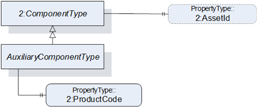
Figure 26 – Overview AuxiliaryComponentType
Table 98 – AuxiliaryComponentType Definition
|
Attribute |
Value |
||||
|
BrowseName |
AuxiliaryComponentType |
||||
|
IsAbstract |
False |
||||
|
References |
Node Class |
BrowseName |
DataType |
TypeDefinition |
Others |
|
Subtype of the ComponentType defined in OPC Unified Architecture for Devices (DI) |
|||||
|
0:HasProperty |
Variable |
2:ProductCode |
0:String |
0:PropertyType |
M |
|
0:HasProperty |
Variable |
2:AssetId |
0:String |
0:PropertyType |
O |
The ProductCode property provides a unique combination of numbers and letters used to identify the product. It may be the order information displayed on type shields or in ERP systems. This property is derived from ComponentType defined in OPC 10000-100.
The AssetId property is a user writable alphanumeric character sequence uniquely identifying a component. The vendor, integrator or user of the device provides the ID. It contains typically an identifier in a branch, use case or user specific naming scheme. This could be for example a reference to an electric scheme. For electric schemes typically EN 81346-2 is used. A use case could be to build up a location-oriented view in a spare part management client software. It enables to identify parts with the same article number which is not possible if this entry is not used. This property is defined by ComponentType defined in OPC 10000-100.
The DriveType describes drives (multi-slot or single-slot axis amplifier) mounted in a controller cabinet or a motion device. When used inside a motion device it should be part of a power train. It is formally defined in Table 99.
B.10.1 shows different possibilities of usage.
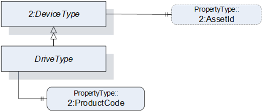
Figure 27 – Overview DriveType
Table 99 – DriveType Definition
|
Attribute |
Value |
||||
|
BrowseName |
DriveType |
||||
|
IsAbstract |
False |
||||
|
References |
Node Class |
BrowseName |
DataType |
TypeDefinition |
Modelling Rule |
|
Subtype of the ComponentType defined in OPC Unified Architecture for Devices (DI) |
|||||
|
0:HasProperty |
Variable |
2:ProductCode |
0:String |
0:PropertyType |
M |
|
The following instance declarations are not defined by this type, but by the supertype ComponentType are repeated here for better readability |
|||||
|
0:HasProperty |
Variable |
2:AssetId |
0:String |
0:PropertyType |
O |
The ProductCode property provides a unique combination of numbers and letters used to identify the product. It may be the order information displayed on type shields or in ERP systems. This property is derived from ComponentType defined in OPC 10000-100.
The AssetId property is a user writable alphanumeric character sequence uniquely identifying a component. The vendor, integrator or user of the device provides the ID. It contains typically an identifier in a branch, use case or user specific naming scheme. This could be for example a reference to an electric scheme. For electric schemes typically EN 81346-2 is used. A use case could be to build up a location-oriented view in a spare part management client software. It enables to identify parts with the same article number which is not possible if this entry is not used. This property is defined by ComponentType defined in OPC 10000-100.
TaskControlType represents instances of task controls of a controller and is formally defined in Table 100.
The task control describes an execution engine that loads and runs task programs. One task runs one task program at the time. The system should instantiate the maximum allowed number of task controls.
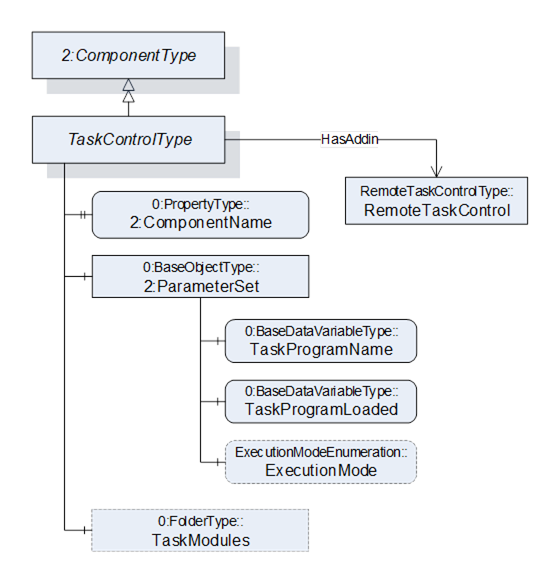
Figure 28 – Overview TaskControlType
Table 100 – TaskControlType Definition
|
Attribute |
Value |
||||
|
BrowseName |
TaskControlType |
||||
|
IsAbstract |
False |
||||
|
References |
Node Class |
BrowseName |
DataType |
TypeDefinition |
Modelling Rule |
|
Subtype of the ComponentType defined in OPC Unified Architecture for Devices (DI) |
|||||
|
0:HasProperty |
Variable |
2:ComponentName |
0:LocalizedText |
0:PropertyType |
M |
|
0:HasComponent |
Object |
2:ParameterSet |
|
0:BaseObjectType |
M |
|
Controls |
Object |
<MotionDeviceIdentifier> |
|
MotionDeviceType |
OP |
|
0:HasAddIn |
Object |
TaskControlOperation |
|
TaskControlOperationType |
O |
|
0:HasComponent |
Object |
TaskModules |
|
0:FolderType |
O |
|
Conformance Units |
|||||
|
Rob Task Control CM Extended |
|||||
|
Rob Task Control Monitor |
|||||
|
Rob Task Control Operation |
|||||
|
Rob Task Control Modules |
|||||
|
Rob MotionDeviceSystem Base |
|||||
The components of the TaskControlType have additional subcomponents which are defined in Table 101.
Table 101 – TaskControlType Additional Subcomponents
|
Source Path |
Reference |
NodeClass |
BrowseName |
DataType |
TypeDefinition |
Others |
|
2:ParameterSet |
0:HasComponent |
Variable |
TaskProgramName |
0:String |
0:BaseDataVariableType |
M |
|
2:ParameterSet |
0:HasComponent |
Variable |
TaskProgramLoaded |
0:Boolean |
0:BaseDataVariableType |
M |
|
2:ParameterSet |
0:HasComponent |
Variable |
ExecutionMode |
ExecutionModeEnumeration |
0:BaseDataVariableType |
O |
|
TaskModules |
0:Organizes |
Object |
<TaskModule> |
|
TaskModuleType |
OP |
The ComponentName property provides a user writeable name provided by the vendor, integrator, or user of the device. The ComponentName of the TaskControlType provides a customer given identifier for the task control or a default name given by the vendor. This property is derived from ComponentType defined in OPC 10000-100.
Object TaskModules is a folder of TaskModuleType (see 7.22) instances that provides more information about the loaded task modules.
Description of ParameterSet of TaskControlType:
- Variable TaskProgramName: The TaskProgramName variable provides a customer given identifier for the task program.
- Variable TaskProgramLoaded: The TaskProgramLoaded variable is TRUE if a task program is loaded in the task control, FALSE otherwise.
- Variable ExecutionMode: The ExecutionMode variable tells how the task control executes the task program (see 10.3).
Controls is a reference to provide the relationship between a task control and a motion device. The InverseName is IsControlledBy.
TaskModuleType provides information about modules loaded on to the TaskControl. It is formally defined in Table 100.
Table 102 – TaskModuleType Definition
|
Attribute |
Value |
||||
|
BrowseName |
TaskModuleType |
||||
|
IsAbstract |
False |
||||
|
References |
Node Class |
BrowseName |
DataType |
TypeDefinition |
Modelling Rule |
|
Subtype of the BaseObjectType defined in OPC Unified Architecture |
|||||
|
0:HasProperty |
Variable |
Name |
0:String |
0:PropertyType |
M |
|
0:HasProperty |
Variable |
Version |
0:String |
0:PropertyType |
O |
|
0:HasProperty |
Variable |
IsReferenced |
0:Boolean |
0:PropertyType |
O |
|
Conformance Units |
|||||
|
Rob Task Control Modules |
|||||
The components of the TaskControlType have additional subcomponents which are defined in Table 101.
Variable Name provides a name for the task module.
Variable Version provides a version information for the task module.
Variable IsReferenced provides a boolean flag to indicate if the module is referenced in other modules and/or the program. This information can be useful to determine if the unloading of a module is possible.
The LoadType is for describing loads mounted on the motion device typically by an integrator or a customer and is formally defined in Table 103. Instances of this ObjectType definition are used to describe the load mounted on one of several mounting points. A common mounting point is the flange of a motion device. Typically, a motion device has additional mounting points on some of the axis. The provided values can either be determined by the robot controller or can be set up by an operator.
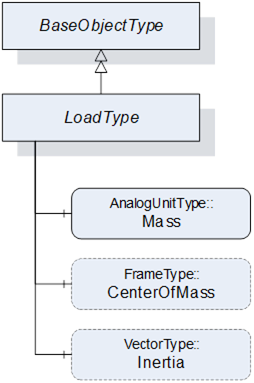
Table 103 – LoadType Definition
|
Attribute |
Value |
||||
|
BrowseName |
LoadType |
||||
|
IsAbstract |
False |
||||
|
References |
Node Class |
BrowseName |
DataType |
TypeDefinition |
Modelling Rule |
|
Subtype of the 0:BaseObjectType defined in OPC Unified Architecture |
|||||
|
0:HasComponent |
Variable |
Mass |
0:Double |
AnalogUnitType |
M |
|
0:HasComponent |
Variable |
CenterOfMass |
0:3DFrame |
3DFrameType |
O |
|
0:HasComponent |
Variable |
Inertia |
0:3DVector |
3DVectorType |
O |
The variable Mass provides the weight of the load mounted on one mounting point. The EngineeringUnits of the Mass shall be provided.
The variable CenterOfMass provides the position and orientation of the center of the mass related to the mounting point using a 3DFrameType. X, Y, Z define the position of the center of gravity relative to the mounting point coordinate system. A, B, C define the orientation of the principal axes of inertia relative to the mounting point coordinate system. Orientation A, B, C can be "0" for systems which do not need these values.
If the instance of the LoadType describes the flange load of a motion device the mounting point coordinate system is the flange coordinate system. If the instance of the LoadType describes an additional load of an axis the mounting point coordinate system is vendor specific and it is up to the vendor to model this coordinate system.
The variable Inertia uses the 3DVectorType to describe the three values of the principal moments of inertia with respect to the mounting point coordinate system. If inertia values are provided for rotary axis the CenterOfMass shall be provided as well.
Table 104 describes the possible degrees of modelling from a minimal one e.g. only the weight of the mass to a complete one comprising weight, center of mass, principal axes, and inertia.
Table 104 – LoadType possible degrees of modelling
|
|
Mass |
CenterOfMass |
Inertia |
X, Y, Z |
A, B, C |
|
|
Mass only |
Used |
- |
- |
- |
|
Mass with center of gravity |
Used |
Used |
0, 0, 0 |
- |
|
Mass with inertia |
Used |
Used |
Used |
Used |
The UserType ObjectType describes information of the registered user groups within the control system.
It is formally defined in Table 105.
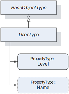
Table 105 – UserType Definition
|
Attribute |
Value |
||||
|
BrowseName |
UserType |
||||
|
IsAbstract |
False |
||||
|
References |
Node Class |
BrowseName |
DataType |
TypeDefinition |
Modelling Rule |
|
Subtype of the BaseObjectType defined in OPC Unified Architecture |
|||||
|
0:HasProperty |
Variable |
Level |
0:String |
0:PropertyType |
M |
|
0:HasProperty |
Variable |
Name |
0:String |
0:PropertyType |
O |
|
Conformance Units |
|||||
|
Rob MotionDeviceSystem Base |
|||||
The Level property provides information about the access rights and determines what can be viewed, updated, or deleted by a user. Depending on the user level different functionalities are available. The robot vendors might use different descriptions and access levels for the users and might require authentication.
The Name property provides the name for the current user within the control system.