
8 OPC UA ObjectTypes
8.1 MachineToolType
The MachineToolType represents the entire machine tool interface of the information model. It is the entry point to the OPC UA interface of a machine tool. It gives a basic structure to the interface. An instance of this type aggregates all information related to one machine tool.
All instances of MachineToolType have to be referenced from the 3:Machines node defined in OPC 40001-1. At least one MachineToolType instance shall be present to qualify for any profile of OPC UA for Machine Tools.
The MachineToolType is formally defined in Table 9.
| Attribute | Value | ||||
| BrowseName | MachineToolType | ||||
| IsAbstract | False | ||||
| References | Node Class | BrowseName | DataType | TypeDefinition | Other |
|---|---|---|---|---|---|
| Subtype of the 0:BaseObjectType defined in OPC 10000-5 i.e. inheriting the InstanceDeclarations of that Node. | |||||
| 0:HasAddIn | Object | 3:Components | 3:MachineComponentsType | O | |
| 0:HasComponent | Object | Equipment | EquipmentType | M | |
| 0:HasAddIn | Object | 2:Identification | MachineToolIdentificationType | M | |
| 0:HasComponent | Object | 3:MachineryBuildingBlocks | 0:FolderType | O | |
| 0:HasComponent | Object | Monitoring | MonitoringType | M | |
| 0:HasComponent | Object | Notification | NotificationType | M | |
| 0:HasComponent | Object | Production | ProductionType | M | |
| 0:HasComponent | Object | 0:FileSystem | 0:FileDirectoryType | O | |
| Conformance Units | |||||
|---|---|---|---|---|---|
| MachineTool MachineToolType Mandatory Nodes | |||||
| MachineTool Components | |||||
| MachineTool FileSystem | |||||
| MachineTool Production Machinery Job Management |
Equipment (see 8.5 ), 2:Identification (see 8.2), Monitoring (see 8.3), Notification (see 8.6) and Production (see 8.4) are instances of the respective types. They are used to structure the information in the MachineToolType topically. 3:Components and 3:MachineryBuildingBlocks are used as described in OPC 40001-1. To differentiate between 3:Components and Equipment, 3:Components should contain elements that are an inseparable part of the machine and Equipment should contain removable elements (e.g., tools).
The components of the MachineToolType have additional subcomponentns which are defined in Table 10.
| Source Path | Reference | NodeClass | BrowseName | DataType | TypeDefinition | Others |
| 0:FileSystem | 0:HasComponent | Object | WorkMasters | 0:FileDirectoryType | O | |
| 3:MachineryBuildingBlocks | 0:HasAddIn | Object | 6:JobManagement | 6:JobManagementType | O |
The 0:FileSystem is the root of all file directories of the OPC UA server and the underlying machine.
Note: While a direct coupling is not essential, aligning the file paths in both OPC UA 0:FileSystem and actual file systems is recommended (e.g. "/Directory1/FileA" in Unix and "ns=1;i=1001 Directory1/FileA" in OPC UA BrowsePath). Harmonizing OPC UA 0:FileSystem with actual file systems is advised for a more intuitive and efficient work environment.
The components of the MachineToolType have additional references which are defined in Table 11. The Production component will be replaced by the 6:JobManagement AddIn of the 3:MachineryBuildingBlocks in future versions of this specification. Hence, Table 11 defines its 0:IsDeprecated Reference.
| SourceBrowsePath | ReferenceType | Is Forward | TargetBrowsePath | ||||
| 3:MachineryBuildingBlocks | 0:HasAddIn | True |
| ||||
| 3:MachineryBuildingBlocks | 0:HasAddIn | True |
| ||||
| 3:MachineryBuildingBlocks | 0:HasAddIn | True |
| ||||
| Production | 0:IsDeprecated | True |
|
8.2 Identification
8.2.1 MachineToolIdentificationType
The MachineToolIdentificationType of the Machine Tools information model holds static data which shall uniquely identify a machine tool among a pool of the machine tool operating entity. It is a subtype of the 3:MachineIdentificationType defined in OPC 40001-1, so it inherits all InstanceDeclarations specified there.
The MachineToolIdentificationType is formally defined in Table 12.
| Attribute | Value | ||||
| BrowseName | MachineToolIdentificationType | ||||
| IsAbstract | False | ||||
| References | Node Class | BrowseName | DataType | TypeDefinition | Other |
|---|---|---|---|---|---|
| Subtype of the 3:MachineIdentificationType defined in OPC 40001-1 i.e. inheriting the InstanceDeclarations of that Node. | |||||
| 0:HasComponent | Object | SoftwareIdentification | 0:BaseObjectType | O | |
| Conformance Units | |||||
|---|---|---|---|---|---|
| MachineTool Identification SoftwareInformation | |||||
| MachineTool Identification Machinery additional |
SoftwareIdentification contains a list of instances of the SoftwareIdentificationType (see Table 14). This list contains the machine tool's software identification information. It allows to add multiple software items, e.g., one for each of PLC, NC and HMI.
2:SoftwareRevision inherited from the 3:MachineIdentificationType shall contain an overall software patch level of the machine tool. Individual software revision numbers may be given using SoftwareIdentification.
For the 2:DeviceClass inherited from the 3:MachineIdentificationType, the values in Table 13 should be used but might be extended by specifications using OPC 40501-1. The most appropriate value, based on the main machine tool technology shall be chosen.
Additive manufacturing machines are not defined in the source mentioned. They include every additive technology currently available.
| DeviceClasses for Machine Tools | |||
| Additive manufacturing machine | Forming machine | Mill-turn machining centre | Shaping machine |
| Additive manufacturing hybrid machine | Gear cutting machine | Nibbling machine | Shearing machine |
| Beading machine | Grinding machine | Other | Slotting machine |
| Bending machine | Hammer machine | Planer | Straightening machine |
| Broaching machine | Hardening machine | Planing machine | Testing machine |
| Copy milling machine | Honing machine | Plasma cutting machine | Thermal deburring machine (TEM) |
| Curling machine | Lapping machine | Polishing machine | Transfer machine |
| Deburring machine | Laser ablation machine | Press | Trimming machine |
| Drawing machine | Laser cutting machine | Profiling machine | Turn-mill machining centre |
| Drilling / Boring machine | Laser drilling machine | Punch laser machine | Turning machine |
| Electrical discharge machine (EDM) | Laser texturing machine | Punching machine | Water jet cutting machine |
| Electro chemical machine (ECM) | Laser welding machine | Riveting machine | |
| Finishing machine | Machining centre | Rolling machine | |
| Flanging machine | Machining centre (other) | Rotary transfer machine | |
| Folding machine | Measuring machine | Sawing machine | |
| Forging machine | Milling machine | Seaming machine | |
All other properties of the MachineToolIdentificationType are defined in OPC 40001-1 and are intended to be used as indicated there.
| BrowsePath | References | NodeClass | BrowseName | DataType | TypeDefinition | Others |
| SoftwareIdentification | 0:HasComponent | Object | <SoftwareItem> | SoftwareIdentificationType | MP |
8.2.2 SoftwareIdentificationType
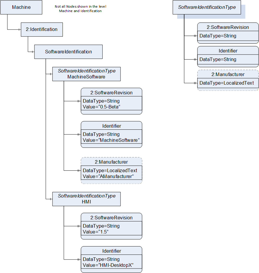
The SoftwareIdentificationType holds information about the specific software in operation in the machine tool. Almost all modern machine tools operate on several software system components, this shall enable presentation of software components (NC Kernel, HMI base system, etc.). Figure 13 shows an example instance of the application of this type within the 2:Identification component of the MachineToolType.
The SoftwareIdentificationType is formally defined in Table 15.
| Attribute | Value | ||||
| BrowseName | SoftwareIdentificationType | ||||
| IsAbstract | False | ||||
| References | Node Class | BrowseName | DataType | TypeDefinition | Other |
|---|---|---|---|---|---|
| Subtype of the 0:BaseObjectType defined in OPC 10000-5 i.e. inheriting the InstanceDeclarations of that Node. | |||||
| 0:HasProperty | Variable | 2:SoftwareRevision | 0:String | 0:PropertyType | M, RO |
| 0:HasProperty | Variable | Identifier | 0:String | 0:PropertyType | M, RO |
| 0:HasProperty | Variable | 2:Manufacturer | 0:LocalizedText | 0:PropertyType | O, RO |
| Conformance Units | |||||
|---|---|---|---|---|---|
| MachineTool Identification SoftwareInformation |
In most cases, machine tools consist of several software components. A software component can be an individual application, or plugin of an application involved in controlling the machine tool.
2:SoftwareRevision provides a string representation of the version or revision level of the software component, the software/firmware of a hardware component. Examples are: "PLL01 1.10.0.3", "V05.01.01.15", "3.1 R1293", "70.0.1".
The Identifier Property provides an identifier to distinguish the software component.
2:Manufacturer refers to the manufacturer/producer of the software.
8.3 Monitoring
8.3.1 MonitoringType
The MonitoringType is used to structure information given in the MachineToolType. It contains the monitoring information of the machine tool and its subsystems.
The MonitoringType is formally defined in Table 16.
| Attribute | Value | ||||
| BrowseName | MonitoringType | ||||
| IsAbstract | False | ||||
| References | Node Class | BrowseName | DataType | TypeDefinition | Other |
|---|---|---|---|---|---|
| Subtype of the 0:BaseObjectType defined in OPC 10000-5 i.e. inheriting the InstanceDeclarations of that Node. | |||||
| 0:HasComponent | Object | <MonitoredElement> | ElementMonitoringType | OP | |
| 0:HasComponent | Object | MachineTool | MachineOperationMonitoringType | M | |
| 0:HasComponent | Object | Stacklight | 4:BasicStacklightType | O | |
| Conformance Units | |||||
|---|---|---|---|---|---|
| MachineTool Monitoring Basic - Stacklight | |||||
| MachineTool Monitoring Basic - Channels |
<MonitoredElement> is an optional Placeholder for ElementMonitoringType instances. This allows for any number of such instances as a component of the MonitoringType. For the DisplayName, it is recommended to use the value of the Name Property of the respective ElementMonitoringType instance.
MachineTool provides overall monitoring information of the machine tool.
Stacklight contains the information about a stacklight's composition and status. It is an object of 4:BasicStacklightType, defined in OPC 10000-200. If the machine tool has a stacklight available, the Stacklight shall be present.
The optional 4:StackLevelType and 4:StackRunningType of the 4:BasicStacklightType shall not be used, only a segmented light shall be shown. Thus, the 4:StacklightMode of each stacklight has to be "Segmented" (0).
As 4:<StackElement>, only elements of 4:StackElementLightType shall be used. For these, the 4:SignalOn, 4:SignalColor and 4:SignalMode shall be used, not the 4:ControlChannelType (see Table 17).
| BrowsePath | References | NodeClass | BrowseName | DataType | TypeDefinition | Other | ||
| Stacklight | 0:HasOrderedComponent | Object | 0:<OrderedObject> | 4:StackElementLightType | MP | |||
| 0:HasProperty | Variable | 4:SignalOn | 0:Boolean | 0:PropertyType | M, RO | ||
| 0:HasComponent | Variable | 4:SignalColor | 4:SignalColor | 0:BaseDataVariableType | M, RO | ||
| 0:HasComponent | Variable | 4:SignalMode | 4:SignalModeLight | 0:BaseDataVariableType | M, RO |
8.3.2 ElementMonitoringType
The ElementMonitoringType is intended to be a supertype for all monitoring information that is specific to a particular element within the machine tool. An element doesn't have to be a physical component. Examples for such elements are NC channels or spindles. It is an abstract type, meaning it is not instantiated, only the subtypes are.
The ElementMonitoringType is formally defined in Table 18.
| Attribute | Value | ||||
| BrowseName | ElementMonitoringType | ||||
| IsAbstract | True | ||||
| References | Node Class | BrowseName | DataType | TypeDefinition | Other |
|---|---|---|---|---|---|
| Subtype of the 0:BaseObjectType defined in OPC 10000-5 i.e. inheriting the InstanceDeclarations of that Node. | |||||
| 0:HasProperty | Variable | Name | 0:String | 0:PropertyType | M, RO |
| Conformance Units |
|---|
The Name property refers to a name of the element.
8.3.3 WorkingUnitMonitoringType
The WorkingUnitMonitoringType is a supertype used to group monitoring information of machine tool elements that are a direct and active part of the machining process. It is an abstract type, meaning it is not instantiated, only the subtypes are.
The WorkingUnitMonitoringType is formally defined in Table 19.
| Attribute | Value | ||||
| BrowseName | WorkingUnitMonitoringType | ||||
| IsAbstract | True | ||||
| References | Node Class | BrowseName | DataType | TypeDefinition | Other |
|---|---|---|---|---|---|
| Subtype of the ElementMonitoringType defined in 8.3.2 i.e. inheriting the InstanceDeclarations of that Node. | |||||
| Conformance Units | |||||
|---|---|---|---|---|---|
| MachineTool Monitoring WorkingUnit |
The WorkingUnitMonitoringType has no other explicitly defined References.
8.3.4 LaserMonitoringType
The LaserMonitoringType provides basic monitoring information of a laser device used in the machining process, e.g., a beam source for a laser beam used as a tool.
The LaserMonitoringType is formally defined in Table 20.
| Attribute | Value | ||||
| BrowseName | LaserMonitoringType | ||||
| IsAbstract | False | ||||
| References | Node Class | BrowseName | DataType | TypeDefinition | Other |
|---|---|---|---|---|---|
| Subtype of the WorkingUnitMonitoringType defined in 8.3.3 i.e. inheriting the InstanceDeclarations of that Node. | |||||
| 0:HasComponent | Variable | ControllerIsOn | 0:Boolean | 0:BaseDataVariableType | M, RO |
| 0:HasComponent | Variable | LaserState | LaserState | 0:BaseDataVariableType | M, RO |
| Conformance Units | |||||
|---|---|---|---|---|---|
| MachineTool Monitoring WorkingUnit |
ControllerIsOn being True indicates that the controller of the laser device is running. This gives no indication whether laser light is currently emitted.
LaserState indicates the current state of a laser device. It is defined in 12.4.
8.3.5 EDMGeneratorMonitoringType
The EDMGeneratorMonitoringType is a collection of information about the EDM spark generator
The EDMGeneratorMonitoringType is formally defined in Table 21
| Attribute | Value | ||||
| BrowseName | EDMGeneratorMonitoringType | ||||
| IsAbstract | False | ||||
| References | Node Class | BrowseName | DataType | TypeDefinition | Other |
|---|---|---|---|---|---|
| Subtype of the WorkingUnitMonitoringType defined in 8.3.3 i.e. inheriting the InstanceDeclarations of that Node. | |||||
| 0:HasComponent | Variable | IsOn | 0:Boolean | 0:BaseDataVariableType | M, RO |
| 0:HasComponent | Variable | EDMGeneratorState | EDMGeneratorState | 0:BaseDataVariableType | M, RO |
| Conformance Units | |||||
|---|---|---|---|---|---|
| MachineTool Monitoring WorkingUnit |
IsOn being True indicates that the EDM spark generator has a valid set of technology parameters, meets all safety conditions required and is switched on.
EDMGeneratorState indicates the current state of the EDM spark generator. It is defined in 12.3.
8.3.6 SpindleMonitoringType
The SpindleMonitoringType is a collection of information about the rotary process axis.
Depending on the actual context of the machine tool, this may for example be a tool-holding milling spindle or a workpiece-holding turning spindle.
The SpindleMonitoringType is formally defined in Table 22.
| Attribute | Value | ||||
| BrowseName | SpindleMonitoringType | ||||
| IsAbstract | False | ||||
| References | Node Class | BrowseName | DataType | TypeDefinition | Other |
|---|---|---|---|---|---|
| Subtype of the WorkingUnitMonitoringType defined in 8.3.3 i.e. inheriting the InstanceDeclarations of that Node. | |||||
| 0:HasComponent | Variable | IsRotating | 0:Boolean | 0:BaseDataVariableType | M, RO |
| 0:HasComponent | Variable | Override | 0:Double | 0:AnalogUnitRangeType | O, RO |
| 0:HasComponent | Variable | IsUsedAsAxis | 0:Boolean | 0:BaseDataVariableType | O, RO |
| Conformance Units | |||||
|---|---|---|---|---|---|
| MachineTool Monitoring WorkingUnit |
IsRotating being True indicates if the spindle is rotating and has a valid commanded rotation speed.
Override is representing the current value of the spindle override.
IsUsedAsAxis being True indicates if the monitored element is used as an axis or, if False, as a spindle. If IsUsedAsAxis is True, the values of IsRotating and Override shall not be used by a client.
8.3.7 ChannelMonitoringType
The ChannelMonitoringType provides the monitoring information about one NC channel.
The ChannelMonitoringType is formally defined in Table 23.
| Attribute | Value | ||||
| BrowseName | ChannelMonitoringType | ||||
| IsAbstract | False | ||||
| References | Node Class | BrowseName | DataType | TypeDefinition | Other |
|---|---|---|---|---|---|
| Subtype of the ElementMonitoringType defined in 8.3.2 i.e. inheriting the InstanceDeclarations of that Node. | |||||
| 0:HasComponent | Variable | ChannelState | ChannelState | 0:BaseDataVariableType | M, RO |
| 0:HasComponent | Variable | ChannelMode | ChannelMode | 0:BaseDataVariableType | M, RO |
| 0:HasComponent | Variable | FeedOverride | 0:Double | 0:AnalogUnitRangeType | M, RO |
| 0:HasComponent | Variable | RapidOverride | 0:Double | 0:AnalogUnitRangeType | O, RO |
| 0:HasComponent | Object | ChannelModifiers | ChannelModifierType | O | |
| Conformance Units | |||||
|---|---|---|---|---|---|
| MachineTool Monitoring Basic - Channels |
ChannelState is representing the current status of the NC channel and is defined in 12.1.
ChannelMode is representing the current mode the NC channel operates in. It is defined in 12.2.
FeedOverride is representing the current value of the feed override of the NC channel.
RapidOverride is representing the current value of the rapid override of the NC channel.
ChannelModifiers is representing additional program modifiers usually used during special operations of the machine tool, e.g., preparation of production (see 8.3.10).
8.3.8 CombinedChannelMonitoringType
The CombinedChannelMonitoringType is a subtype of the ChannelMonitoringType and inherits all its InstanceDeclarations. Using this type instead of a ChannelMonitoringType provides an aggregated representation of the channels in a machine tool. The rules for aggregation are given in Table 24. Sometimes it is not necessary to provide one representation per individual channel, e.g., if one channel is of primary interest, the status of the remaining channels is irrelevant for the machine tool status. It could be used together with the separate channels. Typical applications are multi-spindle machines in which a large number of channels are used for interlinked work steps.
| Component of the CombinedChannelMonitoringType | Rule for Aggregation |
| ChannelState | Mode of the channel not in "active", otherwise "active" - if all channels active --> active - if >0 channel reset --> reset - else interrupted |
| ChannelMode | Mode of the channel not in "automatic", otherwise "automatic" If one or more channel of the combined channels is not in "automatic" the machine tool is not producing (except if the channel is not currently in use). If for example the operator is in JogManual and moving one axis, the whole machine tool is not producing in automatic and the combined channel can be viewed as in JogManual |
| FeedOverride | selection from HMI mirrored On most multi spindle machines there is one HMI which controls the whole machine tool, so most of the input is applied to all combined channels |
| RapidOverride | selection from HMI mirrored On most multi spindle machines there is one HMI which controls the whole machine tool, so most of the input is applied to all combined channels |
| ChannelModifiers | If an element of ChannelModifiers is True in any channel, it has to be True in the combined channel. |
The CombinedChannelMonitoringType is formally defined in Table 25.
| Attribute | Value | ||||
| BrowseName | CombinedChannelMonitoringType | ||||
| IsAbstract | False | ||||
| References | Node Class | BrowseName | DataType | TypeDefinition | Other |
|---|---|---|---|---|---|
| Subtype of the ChannelMonitoringType defined in 8.3.7 i.e. inheriting the InstanceDeclarations of that Node. | |||||
| Conformance Units | |||||
|---|---|---|---|---|---|
| MachineTool Monitoring Basic - Channels |
The CombinedChannelMonitoringType contains no further References than the ones inherited.
8.3.9 MachineOperationMonitoringType
The MachineOperationMonitoringType provides overall monitoring information of the machine tool.
The MachineOperationMonitoringType is formally defined in Table 26.
| Attribute | Value | ||||
| BrowseName | MachineOperationMonitoringType | ||||
| IsAbstract | False | ||||
| References | Node Class | BrowseName | DataType | TypeDefinition | Other |
|---|---|---|---|---|---|
| Subtype of the 0:BaseObjectType defined in OPC 10000-5 i.e. inheriting the InstanceDeclarations of that Node. | |||||
| 0:HasComponent | Variable | FeedOverride | 0:Double | 0:AnalogUnitRangeType | O, RO |
| 0:HasComponent | Variable | IsWarmUp | 0:Boolean | 0:BaseDataVariableType | O, RO |
| 0:HasAddIn | Object | 3:MachineryItemState | 3:MachineryItemState_StateMachineType | O | |
| 0:HasAddIn | Object | 3:MachineryOperationMode | MachineOperationModeStateMachineType | O | |
| 0:HasComponent | Object | Obligation | ObligationType | O | |
| 0:HasComponent | Variable | OperationMode | MachineOperationMode | 0:BaseDataVariableType | M, RO |
| 0:HasComponent | Variable | PowerOnDuration | 0:UInt32 | 0:BaseDataVariableType | O, RO |
| 0:HasAddIn | Object | 2:OperationCounters | 3:MachineryOperationCounterType | O, RO | |
| Conformance Units | |||||
|---|---|---|---|---|---|
| MachineTool MachineToolType Mandatory Nodes | |||||
| MachineTool Monitoring Obligation | |||||
| MachineTool Monitoring Basic - PowerOnDuration | |||||
| MachineTool Monitoring Machinery PowerOnDuration | |||||
| MachineTool Production PartsProducedInLifetime |
FeedOverride is the combined actual feed override value that is effective for the manufacturing program of the machine tool.
IsWarmUp being True indicates if the machine tool is performing a warmup task. A warmup is not used for production, it is the mode used to reach a stable operating point for the machine tool. An example is reaching the optimal operating temperature. This might be indicated by a hardware switch on the machine tool, a special control command, a special production program (referenced by program name) or otherwise. In combination with the 3:MachineryItemState and the 3:MachineryOperationMode, the following behaviour is expected: If IsWarmUp is True, the 3:MachineryItemState is in state 3:Executing and the 3:MachineryOperationMode is in state 3:Setup.
3:MachineryItemState is used as defined in OPC 40001-1. Shall also be referenced as AddIn in the 3:MachineryBuildingBlocks folder.
3:MachineryOperationMode is used as defined in OPC 40001-1. Shall also be referenced as AddIn in the 3:MachineryBuildingBlocks folder.
MaintenanceMode, as a SubStateMachine of the 3:MachineryOperationMode (see Table 29), is only valid if the 0:CurrentState of 3:MachineryOperationMode is 3:Maintenance.
Obligation indicates the instance responsible for the current activities of the machine.
OperationMode contains a MachineOperationMode value as defined in 12.5. The values of the MachineOperationMode enum are derived from the MO modes of machinery functional safety standards. For a machine adhering to such a standard, the OperationMode shall show the respective mode. For a machine not adhering to such a standard, the OperationMode shall be filled with the appropriate mode available from the MachineOperationMode Enum. The OperationMode is only a representation of the machine mode, it shall not be used in a safety relevant manner.
[DEPRECATED in version 1.02] PowerOnDuration is the duration the machine has been powered, meaning all systems have line voltage. It is counted in full hours. This value only increases during the lifetime of the machine and is not reset when the machine is power cycled.
2:OperationCounters with 3:MachineryOperationCounterType is used as defined in OPC 40001-1. Shall also be referenced as AddIn in the 3:MachineryBuildingBlocks folder. It shall contain the 2:PowerOnDuration defined in OPC 40001-1.
2:OperationCounters optionally contains the counter PartsProducedInLifetime, which is the counter for the total number of produced parts during the machine's lifetime. The exact way this number is acquired may differ between different machines. No quality information of PartsProducedInLifetime can be given.
| BrowsePath | References | NodeClass | BrowseName | DataType | TypeDefinition | Other |
| 2:OperationCounters | 0:HasProperty | Variable | 2:PowerOnDuration | 0:Duration | 0:PropertyType | M |
| 2:OperationCounters | 0:HasComponent | Variable | PartsProducedInLifetime | 0:UInt64 | 0:BaseDataVariableType | O, RO |
The PowerOnDuration component will be replaced by the 2:PowerOnDuration of the 2:OperationCounters in future versions of this specification. Hence, Table 28 defines its 0:IsDeprecated Reference.
| SourceBrowsePath | ReferenceType | Is Forward | TargetBrowsePath | ||||
| PowerOnDuration | 0:IsDeprecated | True |
|
8.3.10 MachineOperationModeStateMachineType
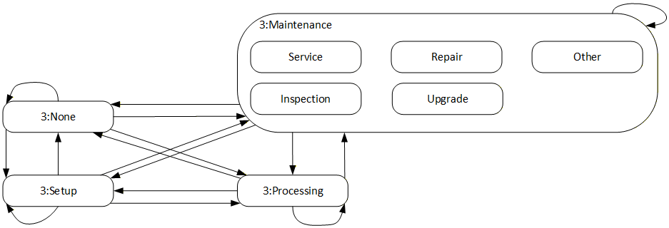
For this specification, the 3:MachineryOperationModeStateMachineType defined in OPC 40001-1 is extended by a sub state for 3:Maintenance. An overview is shown in Figure 14.
| Attribute | Value | ||||
| BrowseName | MachineOperationModeStateMachineType | ||||
| IsAbstract | False | ||||
| References | Node Class | BrowseName | DataType | TypeDefinition | Other |
|---|---|---|---|---|---|
| Subtype of the 3:MachineryOperationModeStateMachineType defined in OPC 40001-1 i.e. inheriting the InstanceDeclarations of that Node. | |||||
| 0:HasProperty | Variable | 0:DefaultInstanceBrowseName | 0:QualifiedName | 0:PropertyType | None |
| 0:HasComponent | Object | 3:None | 0:StateType | None | |
| 0:HasComponent | Object | 3:Maintenance | 0:StateType | None | |
| 0:HasComponent | Object | 3:Processing | 0:StateType | None | |
| 0:HasComponent | Object | 3:Setup | 0:StateType | None | |
| 0:HasComponent | Object | MaintenanceMode | MaintenanceModeStateMachineType | O | |
| 0:HasComponent | Object | 3:FromNoneToMaintenance | 0:TransitionType | None | |
| 0:HasComponent | Object | 3:FromNoneToSetup | 0:TransitionType | None | |
| 0:HasComponent | Object | 3:FromNoneToProcessing | 0:TransitionType | None | |
| 0:HasComponent | Object | 3:FromNoneToNone | 0:TransitionType | None | |
| 0:HasComponent | Object | 3:FromMaintenanceToNone | 0:TransitionType | None | |
| 0:HasComponent | Object | 3:FromMaintenanceToSetup | 0:TransitionType | None | |
| 0:HasComponent | Object | 3:FromMaintenanceToProcessing | 0:TransitionType | None | |
| 0:HasComponent | Object | 3:FromMaintenanceToMaintenance | 0:TransitionType | None | |
| 0:HasComponent | Object | 3:FromSetupToNone | 0:TransitionType | None | |
| 0:HasComponent | Object | 3:FromSetupToMaintenance | 0:TransitionType | None | |
| 0:HasComponent | Object | 3:FromSetupToProcessing | 0:TransitionType | None | |
| 0:HasComponent | Object | 3:FromSetupToSetup | 0:TransitionType | None | |
| 0:HasComponent | Object | 3:FromProcessingToNone | 0:TransitionType | None | |
| 0:HasComponent | Object | 3:FromProcessingToMaintenance | 0:TransitionType | None | |
| 0:HasComponent | Object | 3:FromProcessingToSetup | 0:TransitionType | None | |
| 0:HasComponent | Object | 3:FromProcessingToProcessing | 0:TransitionType | None | |
| Conformance Units | |||||
|---|---|---|---|---|---|
| MachineTool Monitoring MaintenanceMode | |||||
| 3:Machinery Operation Mode |
The state 3:Maintenance is overridden in the MachineOperationModeStateMachineType. The additional references are defined in Table 31. The remaining contents of the state machine are left unchanged, as defined in OPC 40001-1.
| BrowsePath | Value Attribute | Description Attribute | ||
| State Numbers | ||||
| 0:DefaultInstanceBrowseName | 3:MachineryOperationMode | The default BrowseName for instances of the type | ||
| 3:None | - | There is currently no operation mode available | ||
| 3:Maintenance | - | MachineryItem is set into maintenance mode with the intention to carry out maintenance or servicing activities | ||
| 3:Setup | - | MachineryItem is set into setup mode with the intention to carry out setup, preparation or postprocessing activities of a production process | ||
| 3:Processing | - | MachineryItem is set into processing mode with the intention to carry out the value adding activities | ||
| 3:FromNoneToMaintenance | - | Transition from state None to state Maintenance | ||
| 3:FromNoneToSetup | - | Transition from state None to state Setup | ||
| 3:FromNoneToProcessing | - | Transition from state None to state Processing | ||
| 3:FromNoneToNone | - | Transition from state None to state None | ||
| 3:FromMaintenanceToNone | - | Transition from state Maintenance to state None | ||
| 3:FromMaintenanceToSetup | - | Transition from state Maintenance to state Setup | ||
| 3:FromMaintenanceToProcessing | - | Transition from state Maintenance to state Processing | ||
| 3:FromMaintenanceToMaintenance | - | Transition from state Maintenance to state Maintenance | ||
| 3:FromSetupToNone | - | Transition from state Setup to state None | ||
| 3:FromSetupToMaintenance | - | Transition from state Setup to state Maintenance | ||
| 3:FromSetupToProcessing | - | Transition from state Setup to state Processing | ||
| 3:FromSetupToSetup | - | Transition from state Setup to state Setup | ||
| 3:FromProcessingToNone | - | Transition from state Processing to state None | ||
| 3:FromProcessingToMaintenance | - | Transition from state Processing to state Maintenance | ||
| 3:FromProcessingToSetup | - | Transition from state Processing to state Setup | ||
| 3:FromProcessingToProcessing | - | Transition from state Processing to state Processing | ||
| 0 | - | ||
| 1 | - | ||
| 2 | - | ||
| 3 | - | ||
| 0 | |||
| 1 | |||
| 2 | |||
| 3 | |||
| 4 | - | ||
| 5 | - | ||
| 6 | - | ||
| 7 | - | ||
| 8 | - | ||
| 9 | - | ||
| 10 | - | ||
| 11 | - | ||
| 12 | - | ||
| 13 | - | ||
| 14 | - | ||
| 15 | - | ||
| SourceBrowsePath | ReferenceType | Is Forward | TargetBrowsePath |
| 3:Maintenance | 0:HasSubStateMachine | True | MaintenanceMode |
| 3:FromNoneToMaintenance | 0:FromState | True | 3:None |
| 0:ToState | True | 3:Maintenance | |
| 3:FromNoneToProcessing | 0:FromState | True | 3:None |
| 0:ToState | True | 3:Processing | |
| 3:FromNoneToSetup | 0:FromState | True | 3:None |
| 0:ToState | True | 3:Setup | |
| 3:FromMaintenanceToNone | 0:FromState | True | 3:Maintenance |
| 0:ToState | True | 3:None | |
| 3:FromMaintenanceToProcessing | 0:FromState | True | 3:Maintenance |
| 0:ToState | True | 3:Processing | |
| 3:FromMaintenanceToSetup | 0:FromState | True | 3:Maintenance |
| 0:ToState | True | 3:Setup | |
| 3:FromProcessingToNone | 0:FromState | True | 3:Processing |
| 0:ToState | True | 3:None | |
| 3:FromProcessingToMaintenance | 0:FromState | True | 3:Processing |
| 0:ToState | True | 3:Maintenance | |
| 3:FromProcessingToSetup | 0:FromState | True | 3:Processing |
| 0:ToState | True | 3:Setup | |
| 3:FromSetupToNone | 0:FromState | True | 3:Setup |
| 0:ToState | True | 3:None | |
| 3:FromSetupToMaintenance | 0:FromState | True | 3:Setup |
| 0:ToState | True | 3:Maintenance | |
| 3:FromSetupToProcessing | 0:FromState | True | 3:Setup |
| 0:ToState | True | 3:Processing | |
| 3:FromNoneToNone | 0:FromState | True | 3:None |
| 0:ToState | True | 3:None | |
| 3:FromMaintenanceToMaintenance | 0:FromState | True | 3:Maintenance |
| 0:ToState | True | 3:Maintenance | |
| 3:FromProcessingToProcessing | 0:FromState | True | 3:Processing |
| 0:ToState | True | 3:Processing | |
| 3:FromSetupToSetup | 0:FromState | True | 3:Setup |
| 0:ToState | True | 3:Setup |
8.3.11 MaintenanceModeStateMachineType
The MaintenanceModeStateMachineType defines the different modes of maintenance being perfomed on a machine. It is used as a SubStateMachine. If the parent state is not active, the 0:CurrentState Variable of the MaintenanceModeStateMachineType shall have a status equal to Bad_StateNotActive.
The MaintenanceModeStateMachineType is formally defined in Table 32.
| Attribute | Value | ||||
| BrowseName | MaintenanceModeStateMachineType | ||||
| IsAbstract | False | ||||
| References | Node Class | BrowseName | DataType | TypeDefinition | Other |
|---|---|---|---|---|---|
| Subtype of the 0:FiniteStateMachineType defined in OPC 10000-5 i.e. inheriting the InstanceDeclarations of that Node. | |||||
| 0:HasComponent | Object | Service | 0:StateType | None | |
| 0:HasComponent | Object | Inspection | 0:StateType | None | |
| 0:HasComponent | Object | Repair | 0:StateType | None | |
| 0:HasComponent | Object | Upgrade | 0:StateType | None | |
| 0:HasComponent | Object | Other | 0:StateType | None | |
| Conformance Units | |||||
|---|---|---|---|---|---|
| MachineTool Monitoring MaintenanceMode |
The MaintenanceModeStateMachineType does not define an initial state.
The Service state indicates that measures to maintain or increase availability and duration of life are implemented. For example, linear guides are replaced, the bearings are lubricated, or the working area is cleaned.
The Inspection state indicates that the status is evaluated. For example, the lubrication is checked, the expendable parts are examined for wear and tear or the functionality of a workpiece holder is checked.
The Repair state indicates that the functionality of the unit is restored. For example, errors are fixed, or components are replaced.
The Upgrade state indicates that the performance, functionality, etc. of the unit are improved. For example, software upgrades, retrofitting of more powerful modules or modules with a longer duration of life.
The Other state is used if none of the other states apply.
The InstanceDeclarations of the MaintenanceModeStateMachineType have additional Attribute values defined in Table 33.
| BrowsePath | Value Attribute | ||
| 0 | ||
| 1 | ||
| 2 | ||
| 3 | ||
| 4 |
8.3.12 ChannelModifierType
The ChannelModifierType allows to show which modifiers are used while the machine is performing pre-production tests and similar tasks.
The ChannelModifierType is formally defined in Table 34.
| Attribute | Value | ||||
| BrowseName | ChannelModifierType | ||||
| IsAbstract | False | ||||
| References | Node Class | BrowseName | DataType | TypeDefinition | Other |
|---|---|---|---|---|---|
| Subtype of the 0:BaseObjectType defined in OPC 10000-5 i.e. inheriting the InstanceDeclarations of that Node. | |||||
| 0:HasComponent | Variable | BlockSkip | 0:Boolean | 0:BaseDataVariableType | O, RO |
| 0:HasComponent | Variable | DryRun | 0:Boolean | 0:BaseDataVariableType | M, RO |
| 0:HasComponent | Variable | OptionalStop | 0:Boolean | 0:BaseDataVariableType | M, RO |
| 0:HasComponent | Variable | TestMode | 0:Boolean | 0:BaseDataVariableType | O, RO |
| 0:HasComponent | Variable | SingleStep | 0:Boolean | 0:BaseDataVariableType | M, RO |
| Conformance Units | |||||
|---|---|---|---|---|---|
| MachineTool Monitoring Basic - Channels |
BlockSkip being True indicates that specially marked NC program blocks are skipped.
DryRun being True indicates that a test run using with a dedicated axis feed is being performed.
OptionalStop being True indicates that the execution will stop at special machine commands.
TestMode being True indicates a test mode which enables execution of a program without physical axis movement. The machining process may be simulated during program execution.
SingleStep being True indicates if the NC channel operates in single block/single step mode.
8.3.13 ObligationType
The ObligationType is used to indicate the entity responsible for the current activities of the machine. This value is needed for certain KPI standards.
The ObligationType is formally defined in Table 35.
| Attribute | Value | ||||
| BrowseName | ObligationType | ||||
| IsAbstract | False | ||||
| References | Node Class | BrowseName | DataType | TypeDefinition | Other |
|---|---|---|---|---|---|
| Subtype of the 0:BaseObjectType defined in OPC 10000-5 i.e. inheriting the InstanceDeclarations of that Node. | |||||
| 0:HasComponent | Variable | EndUserObligated | 0:Boolean | 0:BaseDataVariableType | M, RO |
| 0:HasComponent | Variable | MachineBuilderObligated | 0:Boolean | 0:BaseDataVariableType | M, RO |
| Conformance Units | |||||
|---|---|---|---|---|---|
| MachineTool Monitoring Obligation |
EndUserObligated being True indicates that the machine's activity is the responsibility of the end user/operator.
MachineBuilderObligated being True indicates that the machine's activity is the responsibility of the machine builder.
Typically, only one of EndUserObligated or MachineBuilderObligated is True, indicating the respective entity as responsible. Both being False indicates the obligation being unclear (e.g., unknown, third entity responsible). Both variables being True should not be used. It is foreseen that further obligation entities may be added in later versions; this way of representation allows for extension.
8.4 Production
8.4.1 ProductionType
[DEPRECATED in version 1.02] The ProductionType will be replaced by the job management defined in OPC 40001-3 in future versions of this specification. Hence the 0:IsDeprecated Reference was added.
As a minimal implementation please only instantiate the mandatory variables. Set NumberInList to the value 0, fill Name according to the mapping in Annex B.2 and implement State, as described below in the respective sections.
The ProductionType is used to structure information given in the MachineToolType. It groups the information about the production plan and the production statistics.
The ProductionType is formally defined in Table 36.
| Attribute | Value | ||||
| BrowseName | ProductionType | ||||
| IsAbstract | False | ||||
| References | Node Class | BrowseName | DataType | TypeDefinition | Other |
|---|---|---|---|---|---|
| Subtype of the 0:BaseObjectType defined in OPC 10000-5 i.e. inheriting the InstanceDeclarations of that Node. | |||||
| 0:HasComponent | Object | ProductionPlan | ProductionJobListType | O | |
| 0:HasComponent | Object | ActiveProgram | ProductionActiveProgramType | M | |
| 0:HasComponent | Object | Statistics | ProductionStatisticsType | O | |
| 0:IsDeprecated | Object | MachineTool_v102 | 0:BaseObjectType | ||
| Conformance Units | |||||
|---|---|---|---|---|---|
| MachineTool MachineToolType Mandatory Nodes | |||||
| MachineTool Production Basic |
ProductionPlan is a list of all job elements currently running and planned for execution.
If there is no job on the machine, there may be no ProductionJob object in the list.
In case the ProductionPlan is used as a dynamic list (i.e., ProductionJobType nodes are being added and deleted), the precondition for deleting any node is that all values of variables represent the final state of the job and are sent to all clients in active subscriptions.
ActiveProgram contains the program that is currently running on the machine. If the machine control discriminates between main and subprograms, this program shall be the main program. It is used in parallel to the ProductionPlan, so it allows for an access of the running program without browsing the jobs in the ProductionPlan. The 0:NumberInList Property of the ActiveProgram shall match the one used in the ProductionPlan for the same program. If the ProductionPlan is not used, it shall be 0.
Statistics is the object that contains statistics information related to production.
8.4.2 ProductionJobListType
[DEPRECATED in version 1.02] The ProductionJobListType will be replaced by the job management defined in OPC 40001-3 in future versions of this specification. Hence the 0:IsDeprecated Reference was added.
The ProductionJobListType is a type used for structuring objects of ProductionJobType in an ordered list structure.
The ProductionJobListType is formally defined in Table 37.
| Attribute | Value | ||||
| BrowseName | ProductionJobListType | ||||
| IsAbstract | False | ||||
| References | Node Class | BrowseName | DataType | TypeDefinition | Other |
|---|---|---|---|---|---|
| Subtype of the 0:OrderedListType defined in OPC 10000-5 i.e. inheriting the InstanceDeclarations of that Node. | |||||
| 0:HasOrderedComponent | Object | 0:<OrderedObject> | ProductionJobType | OP | |
| 0:IsDeprecated | Object | MachineTool_v102 | 0:BaseObjectType | ||
| Conformance Units | |||||
|---|---|---|---|---|---|
| MachineTool Production Job | |||||
| MachineTool Production Dynamic Job List | |||||
| MachineTool Production Job Available |
0:<OrderedObject> is a placeholder for any number of ProductionJobType instances. To indicate the order of jobs on the machine, the 0:NumberInList parameter of the ProductionJobType is used. This index shall be 0 for the first list element and increase by one for each subsequent list element. If jobs are deleted from the list or inserted into the list, the 0:NumberInList has to be adjusted for all following ProductionJobType instances in the list, such that the 0:NumberInList elements always form a sequential series of numbers. For the DisplayName of the 0:<OrderedObject>, it is recommended to use the value of the Identifier Property of the respective ProductionJobType instance.
The 0:NodeVersion and the 0:GeneralModelChangeEventType inherited from the 0:OrderedListType are intended to be used in the way defined in OPC 10000-3 and 7.3.
8.4.3 ProductionJobType
[DEPRECATED in version 1.02] The ProductionJobType will be replaced by the job management defined in OPC 40001-3 in future versions of this specification. Hence the 0:IsDeprecated Reference was added.
The ProductionJobType provides aggregated production data for running a sequence to produce several parts after one preparation mounting.
Examples for such a mounting are putting four raw parts on a pallet for a machining centre, setting up the fitting diameter bars in a turning centre bar feeder or loading a metal sheet from which hundreds of parts can be cut or punched. This sequence shall represent several parts which will usually (but not always) be several identical products. A job may be executed several times.
The ProductionJobType is formally defined in Table 38.
| Attribute | Value | ||||
| BrowseName | ProductionJobType | ||||
| IsAbstract | False | ||||
| References | Node Class | BrowseName | DataType | TypeDefinition | Other |
|---|---|---|---|---|---|
| Subtype of the 0:BaseObjectType defined in OPC 10000-5 i.e. inheriting the InstanceDeclarations of that Node | |||||
| 0:HasProperty | Variable | CustomerOrderIdentifier | 0:String | 0:PropertyType | O, RO |
| 0:HasProperty | Variable | Identifier | 0:String | 0:PropertyType | M, RO |
| 0:HasProperty | Variable | OrderIdentifier | 0:String | 0:PropertyType | O, RO |
| 0:HasComponent | Variable | PartsCompleted | 0:UInt32 | 0:BaseDataVariableType | O, RO |
| 0:HasComponent | Object | PartSets | 0:BaseObjectType | O | |
| 0:HasComponent | Variable | PartsGood | 0:UInt32 | 0:BaseDataVariableType | O, RO |
| 0:HasComponent | Object | ProductionPrograms | 0:OrderedListType | M | |
| 0:HasComponent | Variable | RunsCompleted | 0:UInt32 | 0:BaseDataVariableType | M, RO |
| 0:HasComponent | Variable | RunsPlanned | 0:UInt32 | 0:BaseDataVariableType | M, RO |
| 0:HasComponent | Object | State | ProductionJobStateMachineType | M | |
| 0:HasInterface | ObjectType | 0:IOrderedObjectType | |||
| Applied from 0:IOrderedObjectType | |||||
| 0:HasProperty | Variable | 0:NumberInList | 0:UInt16 | 0:PropertyType | M, RO |
| 0:IsDeprecated | Object | MachineTool_v102 | 0:BaseObjectType | ||
| Conformance Units | |||||
|---|---|---|---|---|---|
| MachineTool Production Job | |||||
| MachineTool Production Dynamic Job List | |||||
| MachineTool Production Job Available | |||||
| MachineTool Production Simple Parts Monitoring |
The components of the ProductionJobType have additional references which are defined in Table 39.
| BrowsePath | References | NodeClass | BrowseName | DataType | TypeDefinition | Others |
| PartSets | 0:HasComponent | Object | <PartSet> | ProductionPartSetType | MP | |
| ProductionPrograms | 0:HasOrderedComponent | Object | 0:<OrderedObject> | ProductionProgramType | MP | |
| RunsPlanned | 0:HasProperty | Variable | IsValid | Boolean | PropertyType | M, RO |
The Identifier is the identifier of the job. This Identifier is used to reference the job in other places of the AddressSpace, e.g., in the ProductionPartTransitionEventType. For this reason, the Identifier shall be unique.
The CustomerOrderIdentifier is used to reference the customer order this job belongs to. This information often originates from an external system handling production organisation (e.g., MES).
The OrderIdentifier is used to reference a company internal order the job belongs to. This information often originates from an external system handling production organisation (e.g., MES).
PartsCompleted indicates how many parts have been completed in the current job including all runs. This counter does not give any indication about the part quality. If PartSets are used, this counter shall be in sync with the respective PartsCompletedPerRun counter.
PartSets contains a list of ProductionPartSetType nodes related to the job. It is a list of the part sets, which contain the parts produced in the current run of the job. For the DisplayName of the <PartSet>, it is recommended to use the value of the Name Property of the respective ProductionPartSetType instance.
PartsGood indicates how many good parts have been completed in the current job including all runs. A part is counted as long as there is no contradicting evidence. Note that such evidence may arise in subsequent processing steps (on different machines), even if a part was counted as good. In this case, the data on the OPC UA Server are not changed retrospectively. If individual Parts are modelled, this counter shall be identical to the number of PartType instances with PartQuality set to Good, CapabilityUnavailable or WillNotBeMeasured.
ProductionPrograms contains a list of ProductionProgramType nodes representing the programs used in the job. This list is made out of at least one instance of ProductionProgramType. The ordering of the programs is displayed using the 0:HasOrderedComponent Reference and the 0:NumberInList component of the ProductionProgramType instance applied from the 0:IOrderedObjectType. The underlying ordering is the call sequence of the programs. The program called first shall have the number 0 and appear first along the OrderedComponents. For the DisplayName of the 0:<OrderedObject>, it is recommended to use the value of the Name Property of the respective ProductionProgramType instance.
The ProductionPrograms may include one single ProductionProgramType instance. If it contains more than one ProductionProgramType instance, the call hierarchy of the programs is not shown in this list. Neither is the relation of programs and channels modelled in the ProductionProgramType. Which programs to include in the list can be chosen by the integrator of the information model (e.g., main program only, subprograms included, …). The list shall include programs relevant to the job and manufacturing of the job, macros and cycles for general purpose tasks are usually not included.
RunsCompleted is a counter that increases after each completed run of the job. This means, the run was not aborted and finished regularly. This counter does not give any indication about the part quality.
RunsPlanned indicates how many times a job should be executed. RunsPlanned has a Property called IsValid, which indicates if the planned number of job runs is known to the machine (True) or not (False). The number of planned job runs not being known occurs in continuous production, that is if the machine is started with the respective job and job runs are repeated endlessly. The production process only ends when the machine is stopped by an external measure (operator or system).
State is an instance representation of the ProductionJobStateMachineType. It indicates the current state the job is in and the transition used to get into this state.
0:NumberInList is used to enumerate ProductionJobType instances used as list elements. This index shall be 0 for the first list element and increase by one for each subsequent list element. If nodes are deleted from the list or inserted into the list, the 0:NumberInList has to be adjusted for all following nodes in the list, such that the 0:NumberInList elements always form a sequential series of numbers.
8.4.4 ProductionProgramType
[DEPRECATED in version 1.02] The ProductionProgramType will be replaced by the job management defined in OPC 40001-3 in future versions of this specification. Hence the 0:IsDeprecated Reference was added.
The ProductionProgramType is the representation of a program. A program is a list of operations that the controller performs in sequence. It's usually a machine-readable file which is needed for the controller to fulfil the job.
The ProductionProgramType is formally defined in Table 40.
| Attribute | Value | ||||
| BrowseName | ProductionProgramType | ||||
| IsAbstract | False | ||||
| References | Node Class | BrowseName | DataType | TypeDefinition | Other |
|---|---|---|---|---|---|
| Subtype of the 0:BaseObjectType defined in OPC 10000-5 i.e. inheriting the InstanceDeclarations of that Node | |||||
| 0:HasProperty | Variable | Name | 0:String | 0:PropertyType | M, RO |
| 0:HasComponent | Object | State | ProductionProgramStateMachineType | O | |
| 0:HasInterface | ObjectType | 0:IOrderedObjectType | |||
| Applied from 0:IOrderedObjectType | |||||
| 0:HasProperty | Variable | 0:NumberInList | 0:UInt16 | 0:PropertyType | M, RO |
| 0:IsDeprecated | Object | MachineTool_v102 | 0:BaseObjectType | ||
| Conformance Units | |||||
|---|---|---|---|---|---|
| MachineTool MachineToolType Mandatory Nodes | |||||
| MachineTool Production Basic |
The Name is used to distinguish and identify programs on a machine.
State is an instance representation of the ProductionProgramStateMachineType. It indicates the current state the part is in and the transition used to get into this state.
0:NumberInList is used to enumerate ProductionProgramType instances used as list elements. This index shall be 0 for the first list element and increase by one for each subsequent list element. If nodes are deleted from the list or inserted into the list, the 0:NumberInList has to be adjusted for all following nodes in the list, such that the 0:NumberInList elements always form a sequential series of numbers.
8.4.5 ProductionActiveProgramType
[DEPRECATED in version 1.02] The ProductionActiveProgramType will be replaced by the job management defined in OPC 40001-3 in future versions of this specification. Hence the 0:IsDeprecated Reference was added.
The ProductionActiveProgramType is used to represent programs that are currently running within the machine.
The ProductionActiveProgramType is formally defined in Table 41.
| Attribute | Value | ||||
| BrowseName | ProductionActiveProgramType | ||||
| IsAbstract | False | ||||
| References | Node Class | BrowseName | DataType | TypeDefinition | Other |
|---|---|---|---|---|---|
| Subtype of the ProductionProgramType defined in 8.4.4 i.e. inheriting the InstanceDeclarations of that Node. | |||||
| 0:HasComponent | Variable | JobNodeId | 0:NodeId | 0:BaseDataVariableType | O, RO |
| 0:HasComponent | Variable | JobIdentifier | 0:String | 0:BaseDataVariableType | O, RO |
| 0:HasComponent | Object | State | ProductionProgramStateMachineType | M | |
| 0:IsDeprecated | Object | MachineTool_v102 | 0:BaseObjectType | ||
| Conformance Units | |||||
|---|---|---|---|---|---|
| MachineTool MachineToolType Mandatory Nodes | |||||
| MachineTool Production Basic |
JobNodeId contains the 0:NodeId of the ProductionJobType instance this program is used in.
JobIdentifier holds the same content as the Identifier Property of the ProductionJobType instance this program is used in.
State is inherited from the ProductionProgramType and overridden to be mandatory.
8.4.6 ProductionPartSetType
[DEPRECATED in version 1.02] The ProductionPartSetType will be replaced by the job management defined in OPC 40001-3 in future versions of this specification. Hence the 0:IsDeprecated Reference was added.
The ProductionPartSetType is used to group parts within a production job. It also contains information about the parts in the group.
It is formally defined in Table 42. Its additional subcomponents are defined in Table 43.
| Attribute | Value | ||||
| BrowseName | ProductionPartSetType | ||||
| IsAbstract | False | ||||
| References | Node Class | BrowseName | DataType | TypeDefinition | Other |
|---|---|---|---|---|---|
| Subtype of the 0:BaseObjectType defined in OPC 10000-5 i.e. inheriting the InstanceDeclarations of that Node | |||||
| 0:HasProperty | Variable | Name | 0:String | 0:PropertyType | O, RO |
| 0:HasComponent | Variable | PartsPlannedPerRun | 0:UInt32 | 0:BaseDataVariableType | M, RO |
| 0:HasComponent | Variable | PartsCompletedPerRun | 0:UInt32 | 0:BaseDataVariableType | M, RO |
| 0:HasComponent | Object | PartsPerRun | 0:BaseObjectType | O | |
| 0:HasProperty | Variable | ContainsMixedParts | 0:Boolean | 0:PropertyType | M, RO |
| 0:IsDeprecated | Object | MachineTool_v102 | 0:BaseObjectType | ||
| Conformance Units | |||||
|---|---|---|---|---|---|
| MachineTool Production Job | |||||
| MachineTool Production Dynamic Job List | |||||
| MachineTool Production Job Available |
| BrowsePath | References | NodeClass | BrowseName | DataType | TypeDefinition | Others |
| PartsPerRun | 0:HasComponent | Object | <Part> | ProductionPartType | MP |
Name is used to specify the type of parts in a group.
PartsPlannedPerRun indicates how many of the parts in this group are intended to be produced in one run of a job.
PartsCompletedPerRun indicates how many parts of this group have been completed in the current run of the job. This counter does not give any indication about the part quality.
PartsPerRun contains a list of the parts in the current run of the job. This list is made out of at least one <Part> instance of ProductionPartType. In each new run of the job, all variables in the part nodes are reset to their initial values. For the DisplayName of the <Part>, it is recommended to use the value of the Name Property of the respective ProductionPartType instance.
ContainsMixedParts indicates if the parts in a ProductionPartSetType may be different from each other (True) or if they are parts of the same type (False).
8.4.7 ProductionPartType
[DEPRECATED in version 1.02] The ProductionPartType will be replaced by the job management defined in OPC 40001-3 in future versions of this specification. Hence the 0:IsDeprecated Reference was added.
The ProductionPartType represents a part. A part is the workpiece of the machine which is treated in the purpose of the machine.
This may be for the purpose of machining, measuring or others, depending on the type of machine.
The ProductionPartType is formally defined in Table 44.
| Attribute | Value | ||||
| BrowseName | ProductionPartType | ||||
| IsAbstract | False | ||||
| References | Node Class | BrowseName | DataType | TypeDefinition | Other |
|---|---|---|---|---|---|
| Subtype of the 0:BaseObjectType defined in OPC 10000-5 i.e. inheriting the InstanceDeclarations of that Node | |||||
| 0:HasProperty | Variable | CustomerOrderIdentifier | 0:String | 0:PropertyType | O, RO |
| 0:HasProperty | Variable | Name | 0:String | 0:PropertyType | M, RO |
| 0:HasProperty | Variable | Identifier | 0:String | 0:PropertyType | O, RO |
| 0:HasComponent | Variable | PartQuality | PartQuality | 0:BaseDataVariableType | M, RO |
| 0:HasComponent | Variable | ProcessIrregularity | ProcessIrregularity | 0:BaseDataVariableType | M, RO |
| 0:HasComponent | Object | State | ProductionPartStateMachineType | O | |
| 0:IsDeprecated | Object | MachineTool_v102 | 0:BaseObjectType | ||
| Conformance Units | |||||
|---|---|---|---|---|---|
| MachineTool Production Job | |||||
| MachineTool Production Dynamic Job List | |||||
| MachineTool Production Job Available |
The Name is used to name a part in production in a machine. This name can be specific to the part (e.g., "MBL30/PartNo32001") or to the type of part (e.g., "M8x10 Bolt Type 15").
The CustomerOrderIdentifier is used to reference the customer order this job belongs to. This information often originates from an external system handling production organisation (e.g., MES).
The Identifier is used to distinguish and identify an individual part in production in a machine. It shall be unique.
PartQuality indicates the part quality. The PartQuality DataType is defined in 12.6.
ProcessIrregularity is used to tell if a process irregularity has been detected. A process irregularity might for example be the breakage of a tool or exceeding a temperature limit on coolant. The ProcessIrregularity DataType is defined in 12.7.
State is an instance representation of the ProductionPartStateMachineType. It indicates the current state in manufacturing the part is in and the transition used to get into this state.
8.4.8 ProductionStateMachineType
[DEPRECATED in version 1.02] The ProductionStateMachineType will be replaced by the job management defined in OPC 40001-3 in future versions of this specification. Hence the 0:IsDeprecated Reference was added.
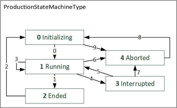
The ProductionStateMachineType shows the states an element in production can be in and the possible transitions between those states. The states and transitions are depicted in Figure 15. Their representation in the OPC UA address space is given in Table 45. The name of each transition consists of the names of the states it connects: [FromState]To[ToState]. Their References are specified in Table 48.
The ProductionStateMachineType is formally defined in Table 45.
| Attribute | Value | ||||
| BrowseName | ProductionStateMachineType | ||||
| IsAbstract | False | ||||
| References | Node Class | BrowseName | DataType | TypeDefinition | Other |
|---|---|---|---|---|---|
| Subtype of the 0:FiniteStateMachineType defined in OPC 10000-5 i.e. inheriting the InstanceDeclarations of that Node. | |||||
| 0:HasComponent | Object | Aborted | 0:StateType | None | |
| 0:HasComponent | Object | AbortedToInitializing | 0:TransitionType | None | |
| 0:HasComponent | Variable | 0:CurrentState | 0:LocalizedText | 0:FiniteStateVariableType | M, RO |
| 0:HasComponent | Object | Ended | 0:StateType | None | |
| 0:HasComponent | Object | EndedToInitializing | 0:TransitionType | None | |
| 0:HasComponent | Object | Initializing | 0:InitialStateType | None | |
| 0:HasComponent | Object | InitializingToAborted | 0:TransitionType | None | |
| 0:HasComponent | Object | InitializingToRunning | 0:TransitionType | None | |
| 0:HasComponent | Object | Interrupted | 0:StateType | None | |
| 0:HasComponent | Object | InterruptedToAborted | 0:TransitionType | None | |
| 0:HasComponent | Object | InterruptedToRunning | 0:TransitionType | None | |
| 0:HasComponent | Variable | 0:LastTransition | 0:LocalizedText | 0:FiniteTransitionVariableType | O, RO |
| 0:HasComponent | Object | Running | 0:StateType | None | |
| 0:HasComponent | Object | RunningToAborted | 0:TransitionType | None | |
| 0:HasComponent | Object | RunningToEnded | 0:TransitionType | None | |
| 0:HasComponent | Object | RunningToInterrupted | 0:TransitionType | None | |
| 0:HasComponent | Object | RunningToRunning | 0:TransitionType | None | |
| 0:IsDeprecated | Object | MachineTool_v102 | 0:BaseObjectType | ||
| Conformance Units | |||||
|---|---|---|---|---|---|
| MachineTool Production LastTransition |
The states and transitions shall have the numbers indicated in Table 47. The 0:Number property of 0:CurrentState and 0:LastTransition shall use those same numbers for the respective state/transition.
The components 0:CurrentState and 0:LastTransition of the ProductionStateMachineType have their optional property 0:Number changed to be mandatory, as defined in Table 46.
| BrowsePath | References | NodeClass | BrowseName | DataType | TypeDefinition | Others |
| 0:CurrentState | 0:HasProperty | Variable | 0:Number | 0:UInt32 | 0:PropertyType | M, RO |
| 0:LastTransition | 0:HasProperty | Variable | 0:Number | 0:UInt32 | 0:PropertyType | M, RO |
The state Aborted indicates that the operation of or on an element in production has been irreversibly stopped before finishing.
Ended is reached when the operation of or on an element in production has finished.
Initializing is the state in which the element in production is being prepared. During this state, the machine doesn't have to be ready for production, although it has to be as soon as the transition InitializingToRunning is used. The production is not yet started.
Interrupted indicates that the execution of or on the element in production has been reversibly halted. This is usually due to an error or an intervention by the operating personnel. It is possible to restart operation of or on the element in production after it was in the interrupted state.
Running indicates that the operation of or on an element in production has been started or re-started and is currently running.
| BrowsePath | Value Attribute | ||
| 0 | ||
| 1 | ||
| 2 | ||
| 3 | ||
| 4 | ||
| 0 | ||
| 1 | ||
| 2 | ||
| 3 | ||
| 4 | ||
| 5 | ||
| 6 | ||
| 7 | ||
| 8 | ||
| 9 |
InitializingToRunning is triggered when the operation of or on an element in production starts.
RunningToEnded is triggered when the operation of or on an element in production finishes.
EndedToInitializing is triggered when re-initialization of the operation of or on an element in production starts.
RunningToRunning is triggered when another consecutive run of the operation of or on an element in production in direct succession starts.
RunningToInterrupted is triggered when the operation of or on an element in production is interrupted.
InterruptedToRunning is triggered when an interruption ends and the operation of or on an element in production continues running.
RunningToAborted is triggered when the operation of or on an element in production is aborted while in the Running state.
InterruptedToAborted is triggered when the operation of or on an element in production is aborted while in the Interrupted state.
AbortedToInitializing is triggered if the operation of or on an element in production is being re-initialized after an abort.
InitializingToAborted is triggered when the operation of or on an element in production is aborted while in the Initializing state.
| SourceBrowsePath | ReferenceType | Is Forward | TargetBrowsePath |
| AbortedToInitializing | 0:FromState | True | Aborted |
| 0:ToState | True | Initializing | |
| EndedToInitializing | 0:FromState | True | Ended |
| 0:ToState | True | Initializing | |
| InitializingToAborted | 0:FromState | True | Initializing |
| 0:ToState | True | Aborted | |
| InitializingToRunning | 0:FromState | True | Initializing |
| 0:ToState | True | Running | |
| InterruptedToAborted | 0:FromState | True | Interrupted |
| 0:ToState | True | Aborted | |
| InterruptedToRunning | 0:FromState | True | Interrupted |
| 0:ToState | True | Running | |
| RunningToAborted | 0:FromState | True | Running |
| 0:ToState | True | Aborted | |
| RunningToEnded | 0:FromState | True | Running |
| 0:ToState | True | Ended | |
| RunningToInterrupted | 0:FromState | True | Running |
| 0:ToState | True | Interrupted | |
| RunningToRunning | 0:FromState | True | Running |
| 0:ToState | True | Running |
8.4.9 ProductionJobStateMachineType
[DEPRECATED in version 1.02] The ProductionJobStateMachineType will be replaced by the job management defined in OPC 40001-3 in future versions of this specification. Hence the 0:IsDeprecated Reference was added.
The ProductionJobStateMachineType shows the states a production job can be in and the possible transitions between those states.
The ProductionJobStateMachineType is formally defined in Table 49.
| Attribute | Value | ||||
| BrowseName | ProductionJobStateMachineType | ||||
| IsAbstract | False | ||||
| References | Node Class | BrowseName | DataType | TypeDefinition | Other |
|---|---|---|---|---|---|
| Subtype of the ProductionStateMachineType defined in 8.4.8 i.e. inheriting the InstanceDeclarations of that Node. | |||||
| 0:GeneratesEvent | ObjectType | InterruptionConditionType | |||
| 0:HasComponent | Object | Aborted | 0:StateType | None | |
| 0:HasComponent | Object | AbortedToInitializing | 0:TransitionType | None | |
| 0:HasComponent | Object | Ended | 0:StateType | None | |
| 0:HasComponent | Object | EndedToInitializing | 0:TransitionType | None | |
| 0:HasComponent | Object | Initializing | 0:InitialStateType | None | |
| 0:HasComponent | Object | InitializingToAborted | 0:TransitionType | None | |
| 0:HasComponent | Object | InitializingToRunning | 0:TransitionType | None | |
| 0:HasComponent | Object | Interrupted | 0:StateType | None | |
| 0:HasComponent | Object | InterruptedToAborted | 0:TransitionType | None | |
| 0:HasComponent | Object | InterruptedToRunning | 0:TransitionType | None | |
| 0:HasComponent | Object | Running | 0:StateType | None | |
| 0:HasComponent | Object | RunningToAborted | 0:TransitionType | None | |
| 0:HasComponent | Object | RunningToEnded | 0:TransitionType | None | |
| 0:HasComponent | Object | RunningToInterrupted | 0:TransitionType | None | |
| 0:HasComponent | Object | RunningToRunning | 0:TransitionType | None | |
| 0:IsDeprecated | Object | MachineTool_v102 | 0:BaseObjectType | ||
| Conformance Units | |||||
|---|---|---|---|---|---|
| MachineTool Production ProductionJobStateMachineType | |||||
| MachineTool Production InterruptionConditionType |
When a new interruption occurs in the production job, an event of InterruptionConditionType can be sent to clarify the reason for the interruption. This is an option in addition to the Interrupted state of the ProductionStateMachineType. It is possible that other interruptions occur while the state machine is in the Interrupted state, e.g., the first interruption being due to a missing part and while the part is still missing, a utility change becomes necessary. In such a case, Events of InterruptionConditionType may be sent for each subsequent interruption. The transition InterruptedToRunning may only be used if no interruption is active. If the interrupted job is aborted (via InterruptedToAborted), the interruption may persist. If a job is then re-initialized via AbortedToInitializing, there are multiple possible cases. In one case the interruption is solved before the job enters the Initializing state. In this case, the same job can transition to Initializing. Another option, when the ProductionPlan is used statically, the job node can be overwritten with the new job being in the Initializing state. Depending on the production context, the interruption of the old job might persist. When the ProductionPlan is used dynamically, a new job node can be created. Whether the interruption can persist is again depending on the production context.
The ProductionJobStateMachineType allows to send Events of ProductionJobTransitionEventType with every transition, as indicated in Table 51. This makes it possible to send all relevant information of the ProductionJobType the state machine instance belongs to with the TransitionEvent.
The state Aborted indicates that the job has been irreversibly stopped before finishing. If the job enters this state, the state machines of any ProductionProgramType and ProductionPartType instances associated with it shall not remain in the state Running.
Ended is reached when the job has finished all its runs, so the value of RunsCompleted is the same as the one for RunsPlanned.
Initializing is the state in which the job is being prepared. That implies the job being scheduled for production in the near future. In this state, actions like e.g., loading and configuring programs, inserting tools and utilities and mounting workpieces may be conducted.
InitializingToRunning is triggered when the job starts. This can only be triggered if all preconditions to start the job are met. A job is usually started by starting a related control routine. This does not result in changes to the components and properties (other than State) of the ProductionJobType instance being started.
RunningToEnded is triggered when the last run of a job finishes. The value of RunsCompleted in the affected ProductionJobType instance is increased by one (and equal to the value of RunsPlanned) due to this transition. In the ProductionJobTransitionEventType, this increased value is sent. This transition also implies that all parts and programs related to the job will no longer change, so e.g., the quality information for each part is finally set.
EndedToInitializing is triggered when initialization of a new job starts. This transition is only used if the nodes in the ProductionPlan are never added or deleted, but remain static in the address space. In this case, all values of the ProductionJobType instance the state machine belongs to are changed to represent a different job. The values of this new job are sent with the ProductionJobTransitionEventType.
RunningToRunning is triggered when a new run of the job starts. The RunsCompleted of the affected ProductionJobType instance increases by one. The ProductionJobTransitionEventType shall send this increased value.
RunningToInterrupted is triggered when the job is interrupted. The point in time the interruption starts shall be when the machine gets the command to interrupt the job process. To indicate the reason for the interruption, an InterruptionConditionType with the appropriate ConditionClass may be sent. The components and properties (other than State) of the affected ProductionJobType instance stay unchanged.
InterruptedToRunning is triggered when an interruption ends and production continues running. This transition requires that no interruption is active, regardless of what interruption initially led to the RunningToInterrupted transition. The components and properties (other than State) of the affected ProductionJobType instance stay unchanged.
InterruptedToAborted is triggered when the job is aborted while in the Interrupted state. This transition does not require the reason for the interruption to be solved. The components and properties (other than State) of the affected ProductionJobType instance stay unchanged.
AbortedToInitializing is triggered if production is being re-initialized after an abort. This transition is only used if the nodes in the ProductionPlan are never added or deleted, but remain static in the address space. In this case, all values of the ProductionJobType instance the state machine belongs to are changed to represent a different job. The values of this new job are sent with the ProductionJobTransitionEventType.
The states and transitions shall have the numbers indicated in Table 50. The 0:Number property of 0:CurrentState and 0:LastTransition shall use those same numbers for the respective state/transition.
| BrowsePath | Value Attribute | ||
| 0 | ||
| 1 | ||
| 2 | ||
| 3 | ||
| 4 | ||
| 0 | ||
| 1 | ||
| 2 | ||
| 3 | ||
| 4 | ||
| 5 | ||
| 6 | ||
| 7 | ||
| 8 | ||
| 9 |
| SourceBrowsePath | ReferenceType | Is Forward | TargetBrowsePath |
| AbortedToInitializing | 0:FromState | True | Aborted |
| 0:ToState | True | Initializing | |
| 0:HasEffect | True | ProductionJobTransitionEventType | |
| EndedToInitializing | 0:FromState | True | Ended |
| 0:ToState | True | Initializing | |
| 0:HasEffect | True | ProductionJobTransitionEventType | |
| InitializingToAborted | 0:FromState | True | Initializing |
| 0:ToState | True | Aborted | |
| 0:HasEffect | True | ProductionJobTransitionEventType | |
| InitializingToRunning | 0:FromState | True | Initializing |
| 0:ToState | True | Running | |
| 0:HasEffect | True | ProductionJobTransitionEventType | |
| InterruptedToAborted | 0:FromState | True | Interrupted |
| 0:ToState | True | Aborted | |
| 0:HasEffect | True | ProductionJobTransitionEventType | |
| InterruptedToRunning | 0:FromState | True | Interrupted |
| 0:ToState | True | Running | |
| 0:HasEffect | True | ProductionJobTransitionEventType | |
| RunningToAborted | 0:FromState | True | Running |
| 0:ToState | True | Aborted | |
| 0:HasEffect | True | ProductionJobTransitionEventType | |
| RunningToEnded | 0:FromState | True | Running |
| 0:ToState | True | Ended | |
| 0:HasEffect | True | ProductionJobTransitionEventType | |
| RunningToInterrupted | 0:FromState | True | Running |
| 0:ToState | True | Interrupted | |
| 0:HasEffect | True | ProductionJobTransitionEventType | |
| RunningToRunning | 0:FromState | True | Running |
| 0:ToState | True | Running | |
| 0:HasEffect | True | ProductionJobTransitionEventType |
8.4.10 ProductionProgramStateMachineType
[DEPRECATED in version 1.02] The ProductionProgramStateMachineType will be replaced by the job management defined in OPC 40001-3 in future versions of this specification. Hence the 0:IsDeprecated Reference was added.
The ProductionProgramStateMachineType shows the states a program can be in and the possible transitions between those states. Their representation in the OPC UA address space is given in Table 54. The name of each transition consists of the names of the states it connects: [FromState]To[ToState].
The ProductionProgramStateMachineType is formally defined in Table 52.
| Attribute | Value | |||||
| BrowseName | ProductionProgramStateMachineType | |||||
| IsAbstract | False | |||||
| References | Node Class | BrowseName | DataType | TypeDefinition | Other | |
|---|---|---|---|---|---|---|
| Subtype of the ProductionStateMachineType defined in 8.4.8 i.e. inheriting the InstanceDeclarations of that Node. | ||||||
| 0:HasComponent | Object | Aborted | 0:StateType | None | ||
| 0:HasComponent | Object | AbortedToInitializing | 0:TransitionType | None | ||
| 0:HasComponent | Object | Ended | 0:StateType | None | ||
| 0:HasComponent | Object | EndedToInitializing | 0:TransitionType | None | ||
| 0:HasComponent | Object | Initializing | 0:InitialStateType | None | ||
| 0:HasComponent | Object | InitializingToAborted | 0:TransitionType | None | ||
| 0:HasComponent | Object | InitializingToRunning | 0:TransitionType | None | ||
| 0:HasComponent | Object | Interrupted | 0:StateType | None | ||
| 0:HasComponent | Object | InterruptedToAborted | 0:TransitionType | None | ||
| 0:HasComponent | Object | InterruptedToRunning | 0:TransitionType | None | ||
| 0:HasComponent | Object | Running | 0:StateType | None | ||
| 0:HasComponent | Object | RunningToAborted | 0:TransitionType | None | ||
| 0:HasComponent | Object | RunningToEnded | 0:TransitionType | None | ||
| 0:HasComponent | Object | RunningToInterrupted | 0:TransitionType | None | ||
| 0:HasComponent | Object | RunningToRunning | 0:TransitionType | None | ||
| 0:IsDeprecated | Object | MachineTool_v102 | 0:BaseObjectType | |||
| Conformance Units | ||||||
|---|---|---|---|---|---|---|
| MachineTool Production ProductionProgramStateMachineType |
The ProductionProgramStateMachineType allows to send Events of ProductionProgramTransitionEventType with every transition, as indicated in Table 54. This makes it possible to send all relevant information of the ProductionProgramType the state machine instance belongs to with the TransitionEvent.
Initializing is the state in which the program is not yet started.
Interrupted indicates that the execution of the program has been paused and can be continued. This might be due to waiting for the execution of a subprogram or until a certain condition is met, e.g., the doors of the machine are closed.
EndedToInitializing is only used if the nodes in the ProductionPlan are never added or deleted, but remain static in the address space. The Transition is triggered when a new program is loaded. In this case, all values of the ProductionProgramType instance the state machine belongs to are changed to represent a different program. The values of this new job are sent with the ProductionProgramTransitionEventType.
The states and transitions shall have the numbers indicated in Table 53. The 0:Number property of 0:CurrentState and 0:LastTransition shall use those same numbers for the respective state/transition.
| BrowsePath | Value Attribute | ||
| 0 | ||
| 1 | ||
| 2 | ||
| 3 | ||
| 4 | ||
| 0 | ||
| 1 | ||
| 2 | ||
| 3 | ||
| 4 | ||
| 5 | ||
| 6 | ||
| 7 | ||
| 8 | ||
| 9 |
| SourceBrowsePath | ReferenceType | Is Forward | TargetBrowsePath |
| AbortedToInitializing | 0:FromState | True | Aborted |
| 0:ToState | True | Initializing | |
| 0:HasEffect | True | ProductionProgramTransitionEventType | |
| EndedToInitializing | 0:FromState | True | Ended |
| 0:ToState | True | Initializing | |
| 0:HasEffect | True | ProductionProgramTransitionEventType | |
| InitializingToAborted | 0:FromState | True | Initializing |
| 0:ToState | True | Aborted | |
| 0:HasEffect | True | ProductionProgramTransitionEventType | |
| InitializingToRunning | 0:FromState | True | Initializing |
| 0:ToState | True | Running | |
| 0:HasEffect | True | ProductionProgramTransitionEventType | |
| InterruptedToAborted | 0:FromState | True | Interrupted |
| 0:ToState | True | Aborted | |
| 0:HasEffect | True | ProductionProgramTransitionEventType | |
| InterruptedToRunning | 0:FromState | True | Interrupted |
| 0:ToState | True | Running | |
| 0:HasEffect | True | ProductionProgramTransitionEventType | |
| RunningToAborted | 0:FromState | True | Running |
| 0:ToState | True | Aborted | |
| 0:HasEffect | True | ProductionProgramTransitionEventType | |
| RunningToEnded | 0:FromState | True | Running |
| 0:ToState | True | Ended | |
| 0:HasEffect | True | ProductionProgramTransitionEventType | |
| RunningToInterrupted | 0:FromState | True | Running |
| 0:ToState | True | Interrupted | |
| 0:HasEffect | True | ProductionProgramTransitionEventType | |
| RunningToRunning | 0:FromState | True | Running |
| 0:ToState | True | Running | |
| 0:HasEffect | True | ProductionProgramTransitionEventType |
8.4.11 ProductionPartStateMachineType
[DEPRECATED in version 1.02] The ProductionPartStateMachineType will be replaced by the job management defined in OPC 40001-3 in future versions of this specification. Hence the 0:IsDeprecated Reference was added.
The ProductionPartStateMachineType shows the states a part can be in and the possible transitions between those states. Their representation in the OPC UA address space is given in Table 57. The name of each transition consists of the names of the states it connects: [FromState]To[ToState].
The ProductionPartStateMachineType is formally defined in Table 55.
| Attribute | Value | |||||
| BrowseName | ProductionPartStateMachineType | |||||
| IsAbstract | False | |||||
| References | Node Class | BrowseName | DataType | TypeDefinition | Other | |
|---|---|---|---|---|---|---|
| Subtype of the ProductionStateMachineType defined in 8.4.8 i.e. inheriting the InstanceDeclarations of that Node. | ||||||
| 0:HasComponent | Object | Aborted | 0:StateType | None | ||
| 0:HasComponent | Object | AbortedToInitializing | 0:TransitionType | None | ||
| 0:HasComponent | Object | Ended | 0:StateType | None | ||
| 0:HasComponent | Object | EndedToInitializing | 0:TransitionType | None | ||
| 0:HasComponent | Object | Initializing | 0:InitialStateType | None | ||
| 0:HasComponent | Object | InitializingToAborted | 0:TransitionType | None | ||
| 0:HasComponent | Object | InitializingToRunning | 0:TransitionType | None | ||
| 0:HasComponent | Object | Interrupted | 0:StateType | None | ||
| 0:HasComponent | Object | InterruptedToAborted | 0:TransitionType | None | ||
| 0:HasComponent | Object | InterruptedToRunning | 0:TransitionType | None | ||
| 0:HasComponent | Object | Running | 0:StateType | None | ||
| 0:HasComponent | Object | RunningToAborted | 0:TransitionType | None | ||
| 0:HasComponent | Object | RunningToEnded | 0:TransitionType | None | ||
| 0:HasComponent | Object | RunningToInterrupted | 0:TransitionType | None | ||
| 0:HasComponent | Object | RunningToRunning | 0:TransitionType | None | ||
| 0:IsDeprecated | Object | MachineTool_v102 | 0:BaseObjectType | |||
| Conformance Units | ||||||
|---|---|---|---|---|---|---|
| MachineTool Production ProductionPartStateMachineType |
The ProductionPartStateMachineType allows to send Events of ProductionPartTransitionEventType with every transition, as indicated in Table 57. This makes it possible to send all relevant information of the ProductionPartType the state machine instance belongs to with the TransitionEvent.
Ended is reached when the production on the part has finished. The PartQuality may be changed while in this state, implying that the part is measured after the production process. The part does not have to be mounted inside the machine while in this state.
Initializing implies the part is scheduled for production, but the machining process on the part has not yet started. The part does not have to be mounted inside the machine while in this state.
Running indicates that the processing of the part within the machine has been started or re-started and is currently running.
InitializingToRunning is triggered when the processing of the part starts. This Transition requires the part to be mounted within the machine.
RunningToEnded is triggered when the processing of the part finishes. This Transition does not require an update of the PartQuality.
The states and transitions shall have the numbers indicated in Table 56. The 0:Number property of 0:CurrentState and 0:LastTransition shall use those same numbers for the respective state/transition.
| BrowsePath | Value Attribute | ||
| 0 | ||
| 1 | ||
| 2 | ||
| 3 | ||
| 4 | ||
| 0 | ||
| 1 | ||
| 2 | ||
| 3 | ||
| 4 | ||
| 5 | ||
| 6 | ||
| 7 | ||
| 8 | ||
| 9 |
| SourceBrowsePath | ReferenceType | Is Forward | TargetBrowsePath |
| AbortedToInitializing | 0:FromState | True | Aborted |
| 0:ToState | True | Initializing | |
| 0:HasEffect | True | ProductionPartTransitionEventType | |
| EndedToInitializing | 0:FromState | True | Ended |
| 0:ToState | True | Initializing | |
| 0:HasEffect | True | ProductionPartTransitionEventType | |
| InitializingToAborted | 0:FromState | True | Initializing |
| 0:ToState | True | Aborted | |
| 0:HasEffect | True | ProductionPartTransitionEventType | |
| InitializingToRunning | 0:FromState | True | Initializing |
| 0:ToState | True | Running | |
| 0:HasEffect | True | ProductionPartTransitionEventType | |
| InterruptedToAborted | 0:FromState | True | Interrupted |
| 0:ToState | True | Aborted | |
| 0:HasEffect | True | ProductionPartTransitionEventType | |
| InterruptedToRunning | 0:FromState | True | Interrupted |
| 0:ToState | True | Running | |
| 0:HasEffect | True | ProductionPartTransitionEventType | |
| RunningToAborted | 0:FromState | True | Running |
| 0:ToState | True | Aborted | |
| 0:HasEffect | True | ProductionPartTransitionEventType | |
| RunningToEnded | 0:FromState | True | Running |
| 0:ToState | True | Ended | |
| 0:HasEffect | True | ProductionPartTransitionEventType | |
| RunningToInterrupted | 0:FromState | True | Running |
| 0:ToState | True | Interrupted | |
| 0:HasEffect | True | ProductionPartTransitionEventType | |
| RunningToRunning | 0:FromState | True | Running |
| 0:ToState | True | Running | |
| 0:HasEffect | True | ProductionPartTransitionEventType |
8.4.12 ProductionStatisticsType
[DEPRECATED in version 1.02] The ProductionType containing the ProductionStatisticsType will be replaced by the job management defined in OPC 40001-3 in future versions of this specification. Hence the 0:IsDeprecated Reference was added for the ProductionStatisticsType. The PartsProducedInLifetime counter is added to the 2:OperationCounters in the MachineOperationMonitoringType (see section 8.3.9).
The ProductionStatisticsType aggregates statistics information related to production on the machine.
The ProductionStatisticsType is formally defined in Table 58.
| Attribute | Value | ||||
| BrowseName | ProductionStatisticsType | ||||
| IsAbstract | False | ||||
| References | Node Class | BrowseName | DataType | TypeDefinition | Other |
|---|---|---|---|---|---|
| Subtype of the 0:BaseObjectType defined in OPC 10000-5 i.e. inheriting the InstanceDeclarations of that Node. | |||||
| 0:HasComponent | Variable | PartsProducedInLifetime | 0:UInt32 | 0:BaseDataVariableType | O, RO |
| 0:IsDeprecated | Object | MachineTool_v102 | 0:BaseObjectType | ||
| Conformance Units | |||||
|---|---|---|---|---|---|
| MachineTool Production Job | |||||
| MachineTool Production PartsProducedInLifetime |
PartsProducedInLifetime is the counter for the total number of produced parts during the machine's lifetime. The exact way this number is acquired may differ between different machines. No quality information of PartsProducedInLifetime can be given.
8.5 Equipment
8.5.1 EquipmentType
The EquipmentType is used to structure elements for machine equipment.
The EquipmentType is formally defined in Table 59.
| Attribute | Value | ||||
| BrowseName | EquipmentType | ||||
| IsAbstract | False | ||||
| References | Node Class | BrowseName | DataType | TypeDefinition | Other |
|---|---|---|---|---|---|
| Subtype of the 0:BaseObjectType defined in OPC 10000-5 i.e. inheriting the InstanceDeclarations of that Node. | |||||
| 0:HasComponent | Object | Tools | ToolListType | O | |
| Conformance Units | |||||
|---|---|---|---|---|---|
| MachineTool MachineToolType Mandatory Nodes | |||||
| MachineTool Equipment ToolIdentification |
Tools is the entry point to the list of BaseToolType subtype instances in the machine. The list of tools provided here shall contain the tools that are present in the machine and the magazines the machine has automated access to.
8.5.2 ToolListType
The ToolListType is a list of tools, where a tool may be a single tool or a multitool.
The ToolListType is formally defined in Table 60.
| Attribute | Value | ||||
| BrowseName | ToolListType | ||||
| IsAbstract | False | ||||
| References | Node Class | BrowseName | DataType | TypeDefinition | Other |
|---|---|---|---|---|---|
| Subtype of the 0:BaseObjectType defined in OPC 10000-5 i.e. inheriting the InstanceDeclarations of that Node. | |||||
| 0:HasComponent | Object | <Tool> | BaseToolType | OP | |
| 0:HasProperty | Variable | 0:NodeVersion | 0:String | 0:PropertyType | O, RO |
| 0:GeneratesEvent | ObjectType | 0:GeneralModelChangeEventType | |||
| Conformance Units | |||||
|---|---|---|---|---|---|
| MachineTool Equipment ToolIdentification | |||||
| MachineTool Equipment Dynamic Tool List |
<Tool> is an OptionalPlaceholder for nodes of BaseToolType. The tool list can thus contain any number of tools, including none. For the DisplayName of the <Tool>, it is recommended to use the value of the Name Property of the respective BaseToolType instance.
The contents of the ToolListType instance can change during the Server runtime (e.g., if tools are inserted into the machine or removed from it). A change in the list can be indicated using the 0:NodeVersion Property and the 0:GeneralModelChangeEventType. The 0:NodeVersion and the 0:GeneralModelChangeEventType are intended to be used in the way defined in OPC 10000-3 and 7.3.
8.5.3 BaseToolType
The BaseToolType serves as a supertype to the ToolType and the MultiToolType. It is an abstract type, meaning it is not instantiated, only the subtypes are.
The BaseToolType is formally defined in Table 61.
| Attribute | Value | |||||
| BrowseName | BaseToolType | |||||
| IsAbstract | True | |||||
| References | Node Class | BrowseName | DataType | TypeDefinition | Other | |
|---|---|---|---|---|---|---|
| Subtype of the 0:BaseObjectType defined in OPC 10000-5 i.e. inheriting the InstanceDeclarations of that Node. | ||||||
| 0:HasProperty | Variable | Identifier | 0:String | 0:PropertyType | O, RO | |
| 0:HasComponent | Object | Location | 0:BaseObjectType | O | ||
| 0:HasProperty | Variable | Name | 0:String | 0:PropertyType | O, RO | |
| Conformance Units | ||||||
|---|---|---|---|---|---|---|
| MachineTool Equipment ToolIdentification | ||||||
| MachineTool Equipment Dynamic Tool List |
| BrowsePath | References | NodeClass | BrowseName | DataType | TypeDefinition | Others |
| Location | 0:HasProperty | Variable | Name | 0:String | 0:PropertyType | M, RO |
| Location | 0:HasProperty | Variable | PlaceNumber | 0:UInt16 | 0:PropertyType | M, RO |
Identifier is a unique identifier for a tool. The Identifier can be used to provide a unique ID given by a superordinated management system. This ID can't be generated on the machine, it has to be transferred to the machine by a global tool management system.
The Location indicates where the tool is located, represented by Name, a name for the tool's location (e.g., the tool magazine) and PlaceNumber, the place number at this location (refer to Table 62). If there is a shared magazine for multiple machines, a tool will be shown in the tool list (see 8.5.1 and 8.5.2) of all machines for which the tool is available.
The Name is used to name a tool to ease recognition. This name can be specific to the tool (e.g., "special_formpress_part294"), to the type of tool (e.g., "8mm drill") or to the program (e.g., "T3").
8.5.4 ToolType
The ToolType is the representation of a tool. Tools are exchangeable components used in a machine to execute the production process and may for example be drills, ball milling heads, cutting inserts, pinching tools and so forth. It may also be a non-contact tool, for example a processing laser.
The ToolType is formally defined in Table 63.
| Attribute | Value | ||||
| BrowseName | ToolType | ||||
| IsAbstract | False | ||||
| References | Node Class | BrowseName | DataType | TypeDefinition | Other |
|---|---|---|---|---|---|
| Subtype of the BaseToolType defined in 8.5.3 i.e. inheriting the InstanceDeclarations of that Node. | |||||
| 0:HasComponent | Variable | ControlIdentifier1 | 0:UInt32 | 0:BaseDataVariableType | M, RO |
| 0:HasComponent | Variable | ControlIdentifier2 | 0:UInt32 | 0:BaseDataVariableType | O, RO |
| 0:HasComponent | Variable | ControlIdentifierInterpretation | ToolManagement | 0:BaseDataVariableType | M, RO |
| 0:HasComponent | Variable | LastUsage | 0:UtcTime | 0:BaseDataVariableType | O, RO |
| 0:HasComponent | Variable | Locked | 0:Boolean | 0:BaseDataVariableType | M, RO |
| 0:HasComponent | Variable | PlannedForOperating | 0:Boolean | 0:BaseDataVariableType | O, RO |
| 0:HasComponent | Object | ToolLife | 0:BaseObjectType | O | |
| Conformance Units | |||||
|---|---|---|---|---|---|
| MachineTool Equipment ToolIdentification | |||||
| MachineTool Equipment Dynamic Tool List | |||||
| MachineTool Equipment ToolLife |
The components of the ToolType have additional references which are defined in Table 64.
| BrowsePath | References | NodeClass | BrowseName | DataType | TypeDefinition | Others |
| Locked | 0:HasProperty | Variable | ReasonForLocking | ToolLocked | 0:PropertyType | M, RO |
| ToolLife | 0:HasComponent | Variable | <ToolLifeEntry> | 0:Number | ToolLifeType | MP, RO |
The two components ControlIdentifier1, ControlIdentifier2 are to be interpreted depending on ControlIdentifierInterpretation (refer to 12.10). This reflects the main methods which CNC-based tool management approaches use. In a ToolNumberBased approach, only ControlIdentifier1 is provided and sufficient to identify the tool. In a system with a ToolGroupBasedManagemet, tools are identified by a group and an indexing number inside this group, which are provided as ControlIdentifier1 and ControlIdentifier2 respectively. Should yet another approach be present in a given system, this is indicated by the ControlIdentifierInterpretation being reported as custom. It shall be noted that this identification data is used to identify the tool in the reference frame of the tool management system inside the machine. In many applications the machine control system uses these identifiers to handle multiple tools which are equivalent and present in the machine as spares. For an identification of the tool inside the NC program or globally, independent of the machine management view, the properties Name and Identifier are provided by the BaseToolType.
LastUsage is the time, where the specific tool was the active tool on a tool carrier for the last time, while the machine was operating in an automatic mode (e.g., for CNC controllers: in Mdi- or Automatic-mode).
The property Locked represents whether the tool was locked from use in processing. If True, the tool was locked. It has an additional property as seen in Table 64, ReasonForLocking. ReasonForLocking is defined in 12.9.
The component PlannedForOperating marks tools which the machine control can already mark as being needed for the running NC program or process when being True.
The ToolLife reports on how the tool use and tool life is being currently managed and how far the use of the tool has progressed. If more than one measurement is provided as <ToolLifeEntry>, they shall show the same value as if only one entry was provided, so they shall not be accumulated by a Client.
8.5.5 MultiToolType
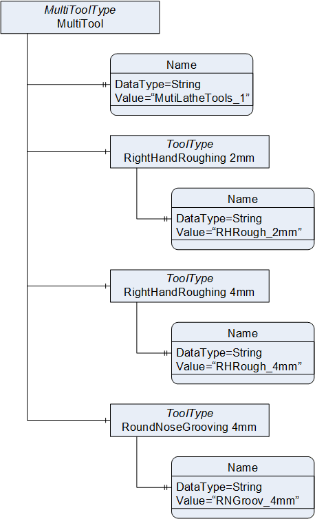
The MultiToolType represents a unit of different tools, usually used in order to have several tools available in-process without requiring explicit tool-changes. Multitools carry several tools on one tool magazine socket or one revolver index position and will be mounted into the machine as one prepared unit.
Typical applications are in turning, when one indexed position of the tool revolver holds several outer-diameter cutting inserts and boring tools, such that a tool change process can quickly complete by merely readjusting the CNC setpoint position tool compensation.
An instance example on how to instantiate the MultiToolType is shown in Figure 16.
The MultiToolType is formally defined in Table 65.
| Attribute | Value | ||||
| BrowseName | MultiToolType | ||||
| IsAbstract | False | ||||
| References | Node Class | BrowseName | DataType | TypeDefinition | Other |
|---|---|---|---|---|---|
| Subtype of the BaseToolType defined in 8.5.3 i.e. inheriting the InstanceDeclarations of that Node. | |||||
| 0:HasComponent | Object | <Tool> | ToolType | OP | |
| Conformance Units | |||||
|---|---|---|---|---|---|
| MachineTool Equipment ToolIdentification | |||||
| MachineTool Equipment Dynamic Tool List |
<Tool> is a placeholder for instances of ToolType. Using this placeholder, the individual ToolType instances making up the MultiTool can be represented in the information model. For individual tools within the MultiTool, use of the Location object is not recommended.
8.6 Notification
8.6.1 NotificationType
The NotificationType is used to structure information given in the MachineToolType. It groups the messages and alerts of the machine and contains the prognoses for the machining operation.
The NotificationType is formally defined in Table 66.
| Attribute | Value | ||||
| BrowseName | NotificationType | ||||
| IsAbstract | False | ||||
| References | Node Class | BrowseName | DataType | TypeDefinition | Other |
|---|---|---|---|---|---|
| Subtype of the 0:BaseObjectType defined in OPC 10000-5 i.e. inheriting the InstanceDeclarations of that Node. | |||||
| 0:HasComponent | Object | Messages | MessagesType | O | |
| 0:HasComponent | Object | Prognoses | PrognosisListType | O | |
| Conformance Units | |||||
|---|---|---|---|---|---|
| MachineTool Notification - Errors and Alerts | |||||
| MachineTool PrognosisType | |||||
| MachineTool Prognoses Dynamic List |
Messages is the node sending events, which are used for errors, warnings and messages. The respective references are formally defined in Table 67.
Prognoses contains a list of the current prognoses for machine operation. Reliability for any prognosis in the list will rely on the specific case and cannot be guaranteed to be precise.
8.6.2 MessagesType
The MessagesType is used to define the object sending events. These events are used for errors, warnings and messages.
The MessagesType is formally defined in Table 67.
| Attribute | Value | ||||
| BrowseName | MessagesType | ||||
| IsAbstract | False | ||||
| References | Node Class | BrowseName | DataType | TypeDefinition | Other |
|---|---|---|---|---|---|
| Subtype of the 0:BaseObjectType defined in OPC 10000-5 i.e. inheriting the InstanceDeclarations of that Node. | |||||
| 0:GeneratesEvent | ObjectType | AlertType | |||
| 0:GeneratesEvent | ObjectType | NotificationEventType | |||
| Conformance Units | |||||
|---|---|---|---|---|---|
| MachineTool Notification - Errors and Alerts |
To differentiate between errors, warnings and messages on the interface, the following convention shall be used, with regard to the recommendations in OPC 10000-5:
Errors have a high 0:Severity between 667 and 1000 and are using an AlertType.
Warnings have a medium 0:Severity between 334 and 666 and are using an AlertType.
Messages have a low 0:Severity lower or equal to 333 and are using a NotificationEventType.
8.6.3 PrognosisListType
The PrognosisListType is a structuring node to collect predictions about future times when certain interaction with the machine may be necessary.
The PrognosisListType is formally defined in Table 68.
| Attribute | Value | ||||
| BrowseName | PrognosisListType | ||||
| IsAbstract | False | ||||
| References | Node Class | BrowseName | DataType | TypeDefinition | Other |
|---|---|---|---|---|---|
| Subtype of the 0:BaseObjectType defined in OPC 10000-5 i.e. inheriting the InstanceDeclarations of that Node. | |||||
| 0:HasComponent | Object | <Prognosis> | PrognosisType | OP | |
| 0:HasProperty | Variable | 0:NodeVersion | String | 0:PropertyType | O, RO |
| 0:GeneratesEvent | ObjectType | 0:GeneralModelChangeEventType | |||
| Conformance Units | |||||
|---|---|---|---|---|---|
| MachineTool PrognosisType | |||||
| MachineTool Prognoses Dynamic List |
<Prognosis> is an optional placeholder for PrognosisType nodes. Thus, the PrognosisListType can have any number of prognoses as components, including none. If the number of prognoses in this list changes during the runtime of the OPC UA server, the 0:NodeVersion and 0:GeneralModelChangeEventType can be used to indicate those changes. The 0:NodeVersion and the 0:GeneralModelChangeEventType are intended to be used in the way defined in OPC 10000-3 and 7.3.
8.6.4 PrognosisType
The PrognosisType is the most basic prognosis type and the supertype to more specific prognosis types. It is an abstract type, meaning it is not instantiated, only the subtypes are.
The PrognosisType is formally defined in Table 69.
| Attribute | Value | ||||
| BrowseName | PrognosisType | ||||
| IsAbstract | True | ||||
| References | Node Class | BrowseName | DataType | TypeDefinition | Other |
|---|---|---|---|---|---|
| Subtype of the 0:BaseObjectType defined in OPC 10000-5 i.e. inheriting the InstanceDeclarations of that Node. | |||||
| 0:HasProperty | Variable | PredictedTime | 0:UtcTime | 0:PropertyType | M, RO |
| Conformance Units | |||||
|---|---|---|---|---|---|
| MachineTool PrognosisType |
PredictedTime is used to indicate the point in time the predicted user interaction will become necessary.
8.6.5 MaintenancePrognosisType
The MaintenancePrognosisType is a prognosis indicating at which time in the future a specific maintenance action may become necessary. The MaintenancePrognosisType is also used if an upcoming maintenance is scheduled for the machine.
Examples may be oil changes, filter mat replacements or regular checks.
The MaintenancePrognosisType is formally defined in Table 70.
| Attribute | Value | ||||
| BrowseName | MaintenancePrognosisType | ||||
| IsAbstract | False | ||||
| References | Node Class | BrowseName | DataType | TypeDefinition | Other |
|---|---|---|---|---|---|
| Subtype of the PrognosisType defined in 8.6.4 i.e. inheriting the InstanceDeclarations of that Node. | |||||
| 0:HasComponent | Variable | Activity | 0:LocalizedText | 0:BaseDataVariableType | M, RO |
| Conformance Units | |||||
|---|---|---|---|---|---|
| MachineTool PrognosisType | |||||
| MachineTool Prognoses Dynamic List |
Activity indicates the specific maintenance task to perform.
8.6.6 ManualActivityPrognosisType
The ManualActivityPrognosisType is a prognosis indicating at which time in the future a manual intervention may become necessary.
An example for a manual intervention is a measurement or control activity, which needs to be carried out during the run of the program.
The ManualActivityPrognosisType is formally defined in Table 71.
| Attribute | Value | ||||
| BrowseName | ManualActivityPrognosisType | ||||
| IsAbstract | False | ||||
| References | Node Class | BrowseName | DataType | TypeDefinition | Other |
|---|---|---|---|---|---|
| Subtype of the PrognosisType defined in 8.6.4 i.e. inheriting the InstanceDeclarations of that Node. | |||||
| 0:HasComponent | Variable | Activity | 0:LocalizedText | 0:BaseDataVariableType | M, RO |
| Conformance Units | |||||
|---|---|---|---|---|---|
| MachineTool PrognosisType | |||||
| MachineTool Prognoses Dynamic List |
Activity indicates the specific maintenance task to perform.
8.6.7 PartLoadPrognosisType
The PartLoadPrognosisType is a prognosis indicating at which time in the future a part needs to be loaded into the machine in order to be processed further.
The PartLoadPrognosisType is formally defined in Table 72.
| Attribute | Value | ||||
| BrowseName | PartLoadPrognosisType | ||||
| IsAbstract | False | ||||
| References | Node Class | BrowseName | DataType | TypeDefinition | Other |
|---|---|---|---|---|---|
| Subtype of the PrognosisType defined in 8.6.4 i.e. inheriting the InstanceDeclarations of that Node. | |||||
| 0:HasComponent | Variable | Location | 0:LocalizedText | 0:BaseDataVariableType | M, RO |
| 0:HasComponent | Variable | PartIdentifier | 0:String | 0:BaseDataVariableType | O, RO |
| 0:HasComponent | Variable | PartName | 0:String | 0:BaseDataVariableType | M, RO |
| 0:HasComponent | Variable | PartNodeId | 0:NodeId | 0:BaseDataVariableType | O, RO |
| Conformance Units | |||||
|---|---|---|---|---|---|
| MachineTool PrognosisType | |||||
| MachineTool Prognoses Dynamic List |
Location is the place where the part to load will be located within the machine. This may for example be the indication and number of the working area.
PartIdentifier shall be identical to the SerialNumber field of the OutputInformationDataType defined in OPC 40001-3 if available. Otherwhise, if the ProductionType is used instead, it shall be identical to the Identifier property of the ProductionPartType instance the prognosis relates to.
PartName shall be identical to the ItemNumber field of the OutputInformationDataType defined in OPC 40001-3. If the ProductionType is used, it shall be identical to the Name property of the ProductionPartType instance the prognosis relates to. If both of these values are unavailable, PartName is filled with the most appropriate value as a name of the part.
[DEPRECATED in version 1.02] PartNodeId shall reference the ProductionPartType instance the prognosis relates to.
The PartNodeId component will not be included in future versions of this specification. Hence, Table 73 defines its 0:IsDeprecated Reference.
| SourceBrowsePath | ReferenceType | Is Forward | TargetBrowsePath | ||||
| PartNodeId | 0:IsDeprecated | True |
|
8.6.8 PartUnloadPrognosisType
The PartUnloadPrognosisType is a prognosis indicating at which time in the future a part unload may become necessary.
The PartUnloadPrognosisType is formally defined in Table 74.
| Attribute | Value | ||||
| BrowseName | PartUnloadPrognosisType | ||||
| IsAbstract | False | ||||
| References | Node Class | BrowseName | DataType | TypeDefinition | Other |
|---|---|---|---|---|---|
| Subtype of the PrognosisType defined in 8.6.4 i.e. inheriting the InstanceDeclarations of that Node. | |||||
| 0:HasComponent | Variable | Location | 0:LocalizedText | 0:BaseDataVariableType | M, RO |
| 0:HasComponent | Variable | PartIdentifier | 0:String | 0:BaseDataVariableType | O, RO |
| 0:HasComponent | Variable | PartName | 0:String | 0:BaseDataVariableType | M, RO |
| 0:HasComponent | Variable | PartNodeId | 0:NodeId | 0:BaseDataVariableType | O, RO |
| Conformance Units | |||||
|---|---|---|---|---|---|
| MachineTool PrognosisType | |||||
| MachineTool Prognoses Dynamic List |
Location is the place where the part to unload is located within the machine. This may for example be the indication and number of the working area.
PartIdentifier shall be identical to the SerialNumber field of the OutputInformationDataType defined in OPC 40001-3 if available. Otherwhise, if the ProductionType is used instead, it shall be identical to the Identifier property of the ProductionPartType instance the prognosis relates to.
PartName shall be identical to the ItemNumber field of the OutputInformationDataType defined in OPC 40001-3. If the ProductionType is used, it shall be identical to the Name property of the ProductionPartType instance the prognosis relates to. If both of these values are unavailable, PartName is filled with the most appropriate value as a name of the part.
[DEPRECATED in version 1.02] PartNodeId shall reference the ProductionPartType instance the prognosis relates to.
The PartNodeId component will not be included in future versions of this specification. Hence, Table 75 defines its 0:IsDeprecated Reference.
| SourceBrowsePath | ReferenceType | Is Forward | TargetBrowsePath | ||||
| PartNodeId | 0:IsDeprecated | True |
|
8.6.9 ProcessChangeoverPrognosisType
The ProcessChangeoverPrognosisType is a prognosis indicating at which time in the future the machine has to be prepared for its next manufacturing process. This might e.g., be the change of a fixture within the machine. It can also be used to group different manual steps like tool changes and loading new parts when done between processes, usually given as setup instruction.
The ProcessChangeoverPrognosisType is formally defined in Table 76.
| Attribute | Value | ||||
| BrowseName | ProcessChangeoverPrognosisType | ||||
| IsAbstract | False | ||||
| References | Node Class | BrowseName | DataType | TypeDefinition | Other |
|---|---|---|---|---|---|
| Subtype of the PrognosisType defined in 8.6.4 i.e. inheriting the InstanceDeclarations of that Node. | |||||
| 0:HasComponent | Variable | Activity | 0:LocalizedText | 0:BaseDataVariableType | M, RO |
| 0:HasComponent | Variable | Location | 0:LocalizedText | 0:BaseDataVariableType | M, RO |
| Conformance Units | |||||
|---|---|---|---|---|---|
| MachineTool PrognosisType | |||||
| MachineTool Prognoses Dynamic List |
Activity indicates the specific task(s) to perform or the indication of the setup instruction.
Location is the place where the activity for the process changeover is located within the machine. This may for example be the indication and number of the working area.
8.6.10 ProductionJobEndPrognosisType
The ProductionJobEndPrognosisType is the estimated point in time of the end of the current Job.
The ProductionJobEndPrognosisType is formally defined in Table 77.
| Attribute | Value | ||||
| BrowseName | ProductionJobEndPrognosisType | ||||
| IsAbstract | False | ||||
| References | Node Class | BrowseName | DataType | TypeDefinition | Other |
|---|---|---|---|---|---|
| Subtype of the PrognosisType defined in 8.6.4 i.e. inheriting the InstanceDeclarations of that Node. | |||||
| 0:HasComponent | Variable | SourceIdentifier | 0:String | 0:BaseDataVariableType | M, RO |
| 0:HasComponent | Variable | JobNodeId | 0:NodeId | 0:BaseDataVariableType | O, RO |
| 0:IsDeprecated | Object | MachineTool_v102 | 0:BaseObjectType | ||
| Conformance Units | |||||
|---|---|---|---|---|---|
| MachineTool PrognosisType | |||||
| MachineTool Prognoses Dynamic List |
The SourceIdentifier Variable shall be identical to the JobOrderID field of the ISA95JobOrderDataType defined in OPC 10031-4. Otherwise, if the ProductionType is used, it shall be identical to the Identifier property belonging to the ProductionJobType the prognosis refers to if modelled in the AddressSpace. Otherwise, it shall contain the identifier of the job.
[DEPRECATED in version 1.02] The JobNodeId shall reference the 0:NodeId of the ProductionJobType instance the prognosis refers to.
The JobNodeId component will not be included in future versions of this specification. Hence, Table 78 defines its 0:IsDeprecated Reference.
| SourceBrowsePath | ReferenceType | Is Forward | TargetBrowsePath | ||||
| JobNodeId | 0:IsDeprecated | True |
|
8.6.11 ToolChangePrognosisType
The ToolChangePrognosisType is a prognosis indicating at which time in the future a tool within the machine or a magazine shall be exchanged with a similar tool (usually due to wear).
The ToolChangePrognosisType is formally defined in Table 79.
| Attribute | Value | ||||
| BrowseName | ToolChangePrognosisType | ||||
| IsAbstract | False | ||||
| References | Node Class | BrowseName | DataType | TypeDefinition | Other |
|---|---|---|---|---|---|
| Subtype of the PrognosisType defined in 8.6.4 i.e. inheriting the InstanceDeclarations of that Node. | |||||
| 0:HasComponent | Variable | Location | 0:LocalizedText | 0:BaseDataVariableType | M, RO |
| 0:HasComponent | Variable | ToolIdentifier | 0:String | 0:BaseDataVariableType | O, RO |
| 0:HasComponent | Variable | ToolName | 0:String | 0:BaseDataVariableType | O, RO |
| 0:HasComponent | Variable | ToolNodeId | 0:NodeId | 0:BaseDataVariableType | O, RO |
| Conformance Units | |||||
|---|---|---|---|---|---|
| MachineTool PrognosisType | |||||
| MachineTool Prognoses Dynamic List |
Location refers to the place the tool shall be removed from within the machine's system boundary, e.g., a tool magazine or the workspace of the machine.
ToolIdentifier is identical to the Identifier property of the tool to change, if applicable. If the tool is not modelled in the AddressSpace of the OPC UA Server, this component shall be filled accordingly.
ToolName contains the name of the tool to change, as described for the BaseToolType in 8.5.3. If the tool is not available in the AddressSpace, the ToolName shall be given in a similar manner.
ToolNodeId is the 0:NodeId of the BaseToolType subtype instance this prognosis refers to.
8.6.12 ToolLoadPrognosisType
The ToolLoadPrognosisType is a prognosis indicating at which time in the future a tool will be loaded into the machine. This prognosis indicates loading a tool within the machine's workspace or a tool magazine the machine has access to. The ToolLoadPrognosisType shall also be used for prognoses to load tools larger than standard tools (which might imply different work routines).
If a tool that already is in the machine is intended to be exchanged with a similar tool, the ToolChangePrognosisType shall be used.
The ToolLoadPrognosisType is formally defined in Table 80.
| Attribute | Value | ||||
| BrowseName | ToolLoadPrognosisType | ||||
| IsAbstract | False | ||||
| References | Node Class | BrowseName | DataType | TypeDefinition | Other |
|---|---|---|---|---|---|
| Subtype of the PrognosisType defined in 8.6.4 i.e. inheriting the InstanceDeclarations of that Node. | |||||
| 0:HasComponent | Variable | Location | 0:LocalizedText | 0:BaseDataVariableType | M, RO |
| 0:HasComponent | Variable | ToolIdentifier | 0:String | 0:BaseDataVariableType | O, RO |
| 0:HasComponent | Variable | ToolName | 0:String | 0:BaseDataVariableType | O, RO |
| Conformance Units | |||||
|---|---|---|---|---|---|
| MachineTool PrognosisType | |||||
| MachineTool Prognoses Dynamic List |
Location refers to the place the tool shall be put within the machine's system boundary, e.g., a tool magazine or the workspace of the machine.
ToolIdentifier contains the unique identifier of the tool. This value shall be the same as for the Identifier Property of the BaseToolType. If the tool is not available in the AddressSpace, the ToolIdentifier shall be given in a similar manner. The ToolIdentifier of ToolLoadPrognosisType and ToolUnloadPrognosisType shall match exactly for the same tool.
ToolName contains the name of the tool, as described for the BaseToolType in 8.5.3. If the tool is not available in the AddressSpace, the ToolName shall be given in a similar manner.
8.6.13 ToolUnloadPrognosisType
The ToolUnloadPrognosisType is a prognosis indicating at which time in the future a tool will be loaded out of the machine or a tool magazine.
The ToolUnloadPrognosisType is formally defined in Table 81.
| Attribute | Value | ||||
| BrowseName | ToolUnloadPrognosisType | ||||
| IsAbstract | False | ||||
| References | Node Class | BrowseName | DataType | TypeDefinition | Other |
|---|---|---|---|---|---|
| Subtype of the PrognosisType defined in 8.6.4 i.e. inheriting the InstanceDeclarations of that Node. | |||||
| 0:HasComponent | Variable | Location | 0:LocalizedText | 0:BaseDataVariableType | M, RO |
| 0:HasComponent | Variable | ToolIdentifier | 0:String | 0:BaseDataVariableType | O, RO |
| 0:HasComponent | Variable | ToolName | 0:String | 0:BaseDataVariableType | O, RO |
| 0:HasComponent | Variable | ToolNodeId | 0:NodeId | 0:BaseDataVariableType | O, RO |
| Conformance Units | |||||
|---|---|---|---|---|---|
| MachineTool PrognosisType | |||||
| MachineTool Prognoses Dynamic List |
Location refers to the place the tool shall be removed from within the machine's system boundary, e.g., a tool magazine or the workspace of the machine.
ToolIdentifier contains the unique identifier of the tool. This value shall be the same as for the Identifier Property of the BaseToolType. If the tool is not available in the AddressSpace, the ToolIdentifier shall be given in a similar manner. The ToolIdentifier of ToolLoadPrognosisType and ToolUnloadPrognosisType shall match exactly for the same tool.
ToolName contains the name of the tool, as described for the BaseToolType in 8.5.3. If the tool is not available in the AddressSpace, the ToolName shall be given in a similar manner.
ToolNodeId contains the 0:NodeId of the appropriate BaseToolType subtype instance.
8.6.14 UtilityChangePrognosisType
The UtilityChangePrognosisType is the estimated point in time at which a utility needs to be refilled or changed. Utilities are for example coolants, filters or scrap material storages.
The UtilityChangePrognosisType is formally defined in Table 82.
| Attribute | Value | ||||
| BrowseName | UtilityChangePrognosisType | ||||
| IsAbstract | False | ||||
| References | Node Class | BrowseName | DataType | TypeDefinition | Other |
|---|---|---|---|---|---|
| Subtype of the PrognosisType defined in 8.6.4 i.e. inheriting the InstanceDeclarations of that Node. | |||||
| 0:HasComponent | Variable | UtilityName | 0:String | 0:BaseDataVariableType | M, RO |
| Conformance Units | |||||
|---|---|---|---|---|---|
| MachineTool PrognosisType | |||||
| MachineTool Prognoses Dynamic List |
UtilityName provides an identifier of the utility to be changed inside the machine. This variable can for example be used by human personnel to prepare the right material for the utility change.