The MonitoringType is used to structure information given in the MachineToolType. It contains the monitoring information of the machine tool and its subsystems.
The MonitoringType is formally defined in Table 15.
Table 15 – MonitoringType Definition
|
Attribute |
Value |
||||
|
BrowseName |
MonitoringType |
||||
|
IsAbstract |
False |
||||
|
References |
Node Class |
BrowseName |
DataType |
TypeDefinition |
Other |
|
Subtype of the 0:BaseObjectType defined in OPC 10000-5 i.e. inheriting the InstanceDeclarations of that Node. |
|||||
|
0:HasComponent |
Object |
<MonitoredElement> |
|
ElementMonitoringType |
OP |
|
0:HasComponent |
Object |
MachineTool |
|
MachineOperationMonitoringType |
M |
|
0:HasComponent |
Object |
Stacklight |
|
4:BasicStacklightType |
O |
|
Conformance Units |
|||||
|
MachineTool Monitoring Basic - Stacklight |
|||||
|
MachineTool Monitoring Basic - PowerOnDuration |
|||||
|
MachineTool Monitoring Basic - Channels |
|||||
<MonitoredElement > is an optional Placeholder for ElementMonitoringType instances. This allows for any number of such instances as a component of the MonitoringType. For the DisplayName, it is recommended to use the value of the Name Property of the respective ElementMonitoringType instance.
MachineTool provides overall monitoring information of the machine tool.
Stacklight contains the information about a stacklight’s composition and status. It is an object of BasicStacklightType, defined in OPC 10000-200. If the machine tool has a stacklight available, the Stacklight shall be present.
The optional 4:StackLevelType and 4:StackRunningType of the 4:BasicStacklightType shall not be used, only a segmented light shall be shown. Thus, the 4:StacklightMode of each stacklight has to be “Segmented” (0).
As 4:<StackElement>, only elements of 4:StackElementLightType shall be used. For these, the 4:SignalOn, 4:SignalColor and 4:SignalMode shall be used, not the 4:ControlChannelType (see Table 16).
Table 16 – MonitoringType Additional Subcomponents
|
BrowsePath |
References |
NodeClass |
BrowseName |
DataType |
TypeDefinition |
Other |
||
|
Stacklight |
0:HasOrderedComponent |
Object |
0:<OrderedObject> |
|
4:StackElementLightType |
MP |
||
|
0:HasProperty |
Variable |
4:SignalOn |
0:Boolean |
0:PropertyType |
M, RO |
||
|
0:HasComponent |
Variable |
4:SignalColor |
4:SignalColor |
0:BaseDataVariableType |
M, RO |
||
|
0:HasComponent |
Variable |
4:SignalMode |
4:SignalModeLight |
0:BaseDataVariableType |
M, RO |
The ElementMonitoringType is intended to be a supertype for all monitoring information that is specific to a particular element within the machine tool. An element doesn’t have to be a physical component. Examples for such elements are NC channels or spindles. It is an abstract type, meaning it is not instantiated, only the subtypes are.
The ElementMonitoringType is formally defined in Table 17.
Table 17 – ElementMonitoringType Definition
|
Attribute |
Value |
||||
|
BrowseName |
ElementMonitoringType |
||||
|
IsAbstract |
True |
||||
|
References |
Node Class |
BrowseName |
DataType |
TypeDefinition |
Other |
|
Subtype of the 0:BaseObjectType defined in OPC 10000-5 i.e. inheriting the InstanceDeclarations of that Node. |
|||||
|
0:HasProperty |
Variable |
Name |
0:String |
0:PropertyType |
M, RO |
|
Conformance Units |
|||||
The Name property refers to a name of the element.
The WorkingUnitMonitoringType is a supertype used to group monitoring information of machine tool elements that are a direct and active part of the machining process. It is an abstract type, meaning it is not instantiated, only the subtypes are.
The WorkingUnitMonitoringType is formally defined in Table 18.
Table 18 – WorkingUnitMonitoringType Definition
|
Attribute |
Value |
||||
|
BrowseName |
WorkingUnitMonitoringType |
||||
|
IsAbstract |
True |
||||
|
References |
Node Class |
BrowseName |
DataType |
TypeDefinition |
Other |
|
Subtype of the ElementMonitoringType defined in 8.3.2 i.e. inheriting the InstanceDeclarations of that Node. |
|||||
|
Conformance Units |
|||||
|
MachineTool Monitoring WorkingUnit |
|||||
The WorkingUnitMonitoringType has no other explicitly defined References.
The LaserMonitoringType provides basic monitoring information of a laser device used in the machining process, i.e. a beam source for a laser beam used as a tool.
The LaserMonitoringType is formally defined in Table 19.
Table 19 – LaserMonitoringType Definition
|
Attribute |
Value |
||||
|
BrowseName |
LaserMonitoringType |
||||
|
IsAbstract |
False |
||||
|
References |
Node Class |
BrowseName |
DataType |
TypeDefinition |
Other |
|
Subtype of the WorkingUnitMonitoringType defined in 8.3.3 i.e. inheriting the InstanceDeclarations of that Node. |
|||||
|
0:HasComponent |
Variable |
ControllerIsOn |
0:Boolean |
0:BaseDataVariableType |
M, RO |
|
0:HasComponent |
Variable |
LaserState |
LaserState |
0:BaseDataVariableType |
M, RO |
|
Conformance Units |
|||||
|
MachineTool Monitoring WorkingUnit |
|||||
ControllerIsOn being True indicates that the controller of the laser device is running. This gives no indication whether laser light is currently emitted.
LaserState indicates the current state of a laser device. It is defined in 12.4.
The EDMGeneratorMonitoringType is a collection of information about the EDM spark generator
The EDMGeneratorMonitoringType is formally defined in Table 20
Table 20 – EDMGeneratorMonitoringType Definition
|
Attribute |
Value |
||||
|
BrowseName |
EDMGeneratorMonitoringType |
||||
|
IsAbstract |
False |
||||
|
References |
Node Class |
BrowseName |
DataType |
TypeDefinition |
Other |
|
Subtype of the WorkingUnitMonitoringType defined in 8.3.3 i.e. inheriting the InstanceDeclarations of that Node. |
|||||
|
0:HasComponent |
Variable |
IsOn |
0:Boolean |
0:BaseDataVariableType |
M, RO |
|
0:HasComponent |
Variable |
EDMGeneratorState |
EDMGeneratorState |
0:BaseDataVariableType |
M, RO |
|
Conformance Units |
|||||
|
MachineTool Monitoring WorkingUnit |
|||||
IsOn being True indicates that the EDM spark generator has a valid set of technology parameters, meets all safety conditions required and is switched on.
EDMGeneratorState indicates the current state of the EDM spark generator. It is defined in 12.3.
The SpindleMonitoringType is a collection of information about the rotary process axis.
Depending on the actual context of the machine tool, this may for example be a tool-holding milling spindle or a workpiece-holding turning spindle.
The SpindleMonitoringType is formally defined in Table 21.
Table 21 – SpindleMonitoringType Definition
|
Attribute |
Value |
||||
|
BrowseName |
SpindleMonitoringType |
||||
|
IsAbstract |
False |
||||
|
References |
Node Class |
BrowseName |
DataType |
TypeDefinition |
Other |
|
Subtype of the WorkingUnitMonitoringType defined in 8.3.3 i.e. inheriting the InstanceDeclarations of that Node. |
|||||
|
0:HasComponent |
Variable |
IsRotating |
0:Boolean |
0:BaseDataVariableType |
M, RO |
|
0:HasComponent |
Variable |
Override |
0:Double |
0:AnalogUnitRangeType |
O, RO |
|
0:HasComponent |
Variable |
IsUsedAsAxis |
0:Boolean |
0:BaseDataVariableType |
O, RO |
|
Conformance Units |
|||||
|
MachineTool Monitoring WorkingUnit |
|||||
IsRotating being True indicates if the spindle is rotating and has a valid commanded rotation speed.
Override is representing the current value of the spindle override.
IsUsedAsAxis being True indicates if the monitored element is used as an axis or, if False, as a spindle. If IsUsedAsAxis is True, the values of IsRotating and Override shall not be used by a client.
The ChannelMonitoringType provides the monitoring information about one NC channel.
The ChannelMonitoringType is formally defined in Table 22.
Table 22 – ChannelMonitoringType Definition
|
Attribute |
Value |
||||
|
BrowseName |
ChannelMonitoringType |
||||
|
IsAbstract |
False |
||||
|
References |
Node Class |
BrowseName |
DataType |
TypeDefinition |
Other |
|
Subtype of the ElementMonitoringType defined in 8.3.2 i.e. inheriting the InstanceDeclarations of that Node. |
|||||
|
0:HasComponent |
Variable |
ChannelState |
ChannelState |
0:BaseDataVariableType |
M, RO |
|
0:HasComponent |
Variable |
ChannelMode |
ChannelMode |
0:BaseDataVariableType |
M, RO |
|
0:HasComponent |
Variable |
FeedOverride |
0:Double |
0:AnalogUnitRangeType |
M, RO |
|
0:HasComponent |
Variable |
RapidOverride |
0:Double |
0:AnalogUnitRangeType |
O, RO |
|
0:HasComponent |
Object |
ChannelModifiers |
|
ChannelModifierType |
O |
|
Conformance Units |
|||||
|
MachineTool Monitoring Basic - Channels |
|||||
ChannelState is representing the current status of the NC channel and is defined in 12.1.
ChannelMode is representing the current mode the NC channel operates in. It is defined in 12.2.
FeedOverride is representing the current value of the feed override of the NC channel.
RapidOverride is representing the current value of the rapid override of the NC channel.
ChannelModifiers is representing additional program modifiers usually used during special operations of the machine tool, e.g. preparation of production (see 8.3.10).
The CombinedChannelMonitoringType is a subtype of the ChannelMonitoringType and inherits all its InstanceDeclarations. Using this type instead of a ChannelMonitoringType provides an aggregated representation of the channels in a machine tool. The rules for aggregation are given in Table 23. Sometimes it is not necessary to provide one representation per individual channel, e.g. if one channel is of primary interest, the status of the remaining channels is irrelevant for the machine tool status. It could be used together with the separate channels. Typical applications are multi-spindle machines in which a large number of channels are used for interlinked work steps.
Table 23 – Rules for Aggregation of the CombinedChannelMonitoringType
|
Component of the CombinedChannelMonitoringType |
Rule for Aggregation |
|
ChannelState |
Mode of the channel not in “active”, otherwise “active” - if all channels active --> active - if >0 channel reset --> reset - else interrupted |
|
ChannelMode |
Mode of the channel not in “automatic”, otherwise “automatic” If one or more channel of the combined channels is not in “automatic” the machine tool is not producing (except if the channel is not currently in use). If for example the operator is in JogManual and moving one axis, the whole machine tool is not producing in automatic and the combined channel can be viewed as in JogManual |
|
FeedOverride |
selection from HMI mirrored On most multi spindle machines there is one HMI which controls the whole machine tool, so most of the input is applied to all combined channels |
|
RapidOverride |
selection from HMI mirrored On most multi spindle machines there is one HMI which controls the whole machine tool, so most of the input is applied to all combined channels |
|
ChannelModifiers |
If an element of ChannelModifiers is True in any channel, it has to be True in the combined channel. |
The CombinedChannelMonitoringType is formally defined in Table 24.
Table 24 – CombinedChannelMonitoringType Definition
|
Attribute |
Value |
||||
|
BrowseName |
CombinedChannelMonitoringType |
||||
|
IsAbstract |
False |
||||
|
References |
Node Class |
BrowseName |
DataType |
TypeDefinition |
Other |
|
Subtype of the ChannelMonitoringType defined in 8.3.7 i.e. inheriting the InstanceDeclarations of that Node. |
|||||
|
Conformance Units |
|||||
|
MachineTool Monitoring Basic - Channels |
|||||
The CombinedChannelMonitoringType contains no further References than the ones inherited.
The MachineOperationMonitoringType provides overall monitoring information of the machine tool.
The MachineOperationMonitoringType is formally defined in Table 25.
Table 25 – MachineOperationMonitoringType Definition
|
Attribute |
Value |
||||
|
BrowseName |
MachineOperationMonitoringType |
||||
|
IsAbstract |
False |
||||
|
References |
Node Class |
BrowseName |
DataType |
TypeDefinition |
Other |
|
Subtype of the 0:BaseObjectType defined in OPC 10000-5 i.e. inheriting the InstanceDeclarations of that Node. |
|||||
|
0:HasComponent |
Variable |
FeedOverride |
0:Double |
0:AnalogUnitRangeType |
O, RO |
|
0:HasComponent |
Variable |
IsWarmUp |
0:Boolean |
0:BaseDataVariableType |
O, RO |
|
0:HasAddIn |
Object |
3:MachineryItemState |
|
3:MachineryItemState_StateMachineType |
O |
|
0:HasAddIn |
Object |
3:MachineryOperationMode |
|
MachineOperationModeStateMachineType |
O |
|
0:HasComponent |
Object |
Obligation |
|
ObligationType |
O |
|
0:HasComponent |
Variable |
OperationMode |
MachineOperationMode |
0:BaseDataVariableType |
M, RO |
|
0:HasComponent |
Variable |
PowerOnDuration |
0:UInt32 |
0:BaseDataVariableType |
O, RO |
|
Conformance Units |
|||||
|
MachineTool MachineToolType Mandatory Nodes |
|||||
|
MachineTool Monitoring Obligation |
|||||
FeedOverride is the combined actual feed override value that is effective for the manufacturing program of the machine tool.
IsWarmUp being True indicates if the machine tool is performing a warmup task. A warmup is not used for production, it is the mode used to reach a stable operating point for the machine tool. An example is reaching the optimal operating temperature. This might be indicated by a hardware switch on the machine tool, a special control command, a special production program (referenced by program name) or otherwise. In combination with the MachineryItemState and the MachineryOperationMode, the following behaviour is expected: If IsWarmUp is True, the MachineryItemState is in State Executing and the MachineryOperationMode is in State Setup.
MachineryItemState is used as defined in OPC 40001-1. Shall also be referenced as AddIn in the MachineryBuildingBlocks Folder.
MachineryOperationMode is used as defined in OPC 40001-1. Shall also be referenced as AddIn in the MachineryBuildingBlocks Folder.
MaintenanceMode, as a SubStateMachine of the MachineryOperationMode (see Table 26), is only valid if the CurrentState of MachineryOperationMode is Maintenance.
Obligation indicates the instance responsible for the current activities of the machine.
OperationMode contains a MachineOperationMode value as defined in 12.5. The values of the MachineOperationMode enum are derived from the MO modes of machinery functional safety standards. For a machine adhering to such a standard, the OperationMode shall show the respective mode. For a machine not adhering to such a standard, the OperationMode shall be filled with the appropriate mode available from the MachineOperationMode Enum. The OperationMode is only a representation of the machine mode, it shall not be used in a safety relevant manner.
PowerOnDuration is the duration the machine has been powered, meaning all systems have line voltage. It is counted in full hours. This value only increases during the lifetime of the machine and is not reset when the machine is power cycled.
For this specification, the MachineryOperationStateMachineType defined in OPC 40001-1 is extended by a SubState for Maintenance. An overview is shown in Figure 14.
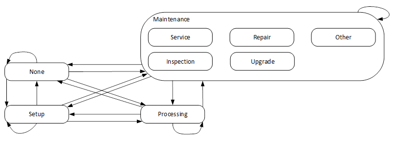
Figure 14 – The States and Transitions of the MachineOperationModeStateMachineType with Maintenance SubStates
Table 26 – MachineOperationModeStateMachineType Definition
|
Attribute |
Value |
||||
|
BrowseName |
MachineOperationModeStateMachineType |
||||
|
IsAbstract |
False |
||||
|
References |
Node Class |
BrowseName |
DataType |
TypeDefinition |
Other |
|
Subtype of the 3:MachineryOperationModeStateMachineType defined in OPC 40001-1 i.e. inheriting the InstanceDeclarations of that Node. |
|||||
|
0:HasProperty |
Variable |
0:DefaultInstanceBrowseName |
0:QualifiedName |
0:PropertyType |
None |
|
0:HasComponent |
Object |
3:None |
|
0:StateType |
None |
|
0:HasComponent |
Object |
3:Maintenance |
|
0:StateType |
None |
|
0:HasComponent |
Object |
3:Processing |
|
0:StateType |
None |
|
0:HasComponent |
Object |
3:Setup |
|
0:StateType |
None |
|
0:HasComponent |
Object |
MaintenanceMode |
|
MaintenanceModeStateMachineType |
O |
|
0:HasComponent |
Object |
3:FromNoneToMaintenance |
|
0:TransitionType |
None |
|
0:HasComponent |
Object |
3:FromNoneToSetup |
|
0:TransitionType |
None |
|
0:HasComponent |
Object |
3:FromNoneToProcessing |
|
0:TransitionType |
None |
|
0:HasComponent |
Object |
3:FromNoneToNone |
|
0:TransitionType |
None |
|
0:HasComponent |
Object |
3:FromMaintenanceToNone |
|
0:TransitionType |
None |
|
0:HasComponent |
Object |
3:FromMaintenanceToSetup |
|
0:TransitionType |
None |
|
0:HasComponent |
Object |
3:FromMaintenanceToProcessing |
|
0:TransitionType |
None |
|
0:HasComponent |
Object |
3:FromMaintenanceToMaintenance |
|
0:TransitionType |
None |
|
0:HasComponent |
Object |
3:FromSetupToNone |
|
0:TransitionType |
None |
|
0:HasComponent |
Object |
3:FromSetupToMaintenance |
|
0:TransitionType |
None |
|
0:HasComponent |
Object |
3:FromSetupToProcessing |
|
0:TransitionType |
None |
|
0:HasComponent |
Object |
3:FromSetupToSetup |
|
0:TransitionType |
None |
|
0:HasComponent |
Object |
3:FromProcessingToNone |
|
0:TransitionType |
None |
|
0:HasComponent |
Object |
3:FromProcessingToMaintenance |
|
0:TransitionType |
None |
|
0:HasComponent |
Object |
3:FromProcessingToSetup |
|
0:TransitionType |
None |
|
0:HasComponent |
Object |
3:FromProcessingToProcessing |
|
0:TransitionType |
None |
|
Conformance Units |
|||||
|
MachineTool Monitoring MaintenanceMode |
|||||
|
3:Machinery Operation Mode |
|||||
The state Maintenance is overridden in the MachineOperationStateMachineType. The additional references are defined in Table 28. The remaining contents of the state machine are left unchanged, as defined in OPC 40001-1.
Table 27 – MachineOperationModeStateMachineType Attribute Values for Child Nodes
|
BrowsePath |
Value Attribute |
Description Attribute |
||
|
State Numbers |
||||
|
0:DefaultInstanceBrowseName |
3:MachineryOperationMode |
The default BrowseName for instances of the type |
||
|
3:None |
- |
There is currently no operation mode available |
||
|
3:Maintenance |
- |
MachineryItem is set into maintenance mode with the intention to carry out maintenance or servicing activities |
||
|
3:Setup |
- |
MachineryItem is set into setup mode with the intention to carry out setup, preparation or postprocessing activities of a production process |
||
|
3:Processing |
- |
MachineryItem is set into processing mode with the intention to carry out the value adding activities |
||
|
3:FromNoneToMaintenance |
- |
Transition from state None to state Maintenance |
||
|
3:FromNoneToSetup |
- |
Transition from state None to state Setup |
||
|
3:FromNoneToProcessing |
- |
Transition from state None to state Processing |
||
|
3:FromNoneToNone |
- |
Transition from state None to state None |
||
|
3:FromMaintenanceToNone |
- |
Transition from state Maintenance to state None |
||
|
3:FromMaintenanceToSetup |
- |
Transition from state Maintenance to state Setup |
||
|
3:FromMaintenanceToProcessing |
- |
Transition from state Maintenance to state Processing |
||
|
3:FromMaintenanceToMaintenance |
- |
Transition from state Maintenance to state Maintenance |
||
|
3:FromSetupToNone |
- |
Transition from state Setup to state None |
||
|
3:FromSetupToMaintenance |
- |
Transition from state Setup to state Maintenance |
||
|
3:FromSetupToProcessing |
- |
Transition from state Setup to state Processing |
||
|
3:FromSetupToSetup |
- |
Transition from state Setup to state Setup |
||
|
3:FromProcessingToNone |
- |
Transition from state Processing to state None |
||
|
3:FromProcessingToMaintenance |
- |
Transition from state Processing to state Maintenance |
||
|
3:FromProcessingToSetup |
- |
Transition from state Processing to state Setup |
||
|
3:FromProcessingToProcessing |
- |
Transition from state Processing to state Processing |
||
|
0 |
- |
||
|
1 |
- |
||
|
2 |
- |
||
|
3 |
- |
||
|
0 |
|
||
|
1 |
|
||
|
2 |
|
||
|
3 |
|
||
|
4 |
- |
||
|
5 |
- |
||
|
6 |
- |
||
|
7 |
- |
||
|
8 |
- |
||
|
9 |
- |
||
|
10 |
- |
||
|
11 |
- |
||
|
12 |
- |
||
|
13 |
- |
||
|
14 |
- |
||
|
15 |
- |
||
Table 28 – MachineOperationModeStateMachineType Additional References
|
SourceBrowsePath |
ReferenceType |
Is Forward |
TargetBrowsePath |
|
3:Maintenance |
0:HasSubStateMachine |
True |
MaintenanceMode |
|
3:FromNoneToMaintenance |
0:FromState |
True |
3:None |
|
|
0:ToState |
True |
3:Maintenance |
|
3:FromNoneToProcessing |
0:FromState |
True |
3:None |
|
|
0:ToState |
True |
3:Processing |
|
3:FromNoneToSetup |
0:FromState |
True |
3:None |
|
|
0:ToState |
True |
3:Setup |
|
3:FromMaintenanceToNone |
0:FromState |
True |
3:Maintenance |
|
|
0:ToState |
True |
3:None |
|
3:FromMaintenanceToProcessing |
0:FromState |
True |
3:Maintenance |
|
|
0:ToState |
True |
3:Processing |
|
3:FromMaintenanceToSetup |
0:FromState |
True |
3:Maintenance |
|
|
0:ToState |
True |
3:Setup |
|
3:FromProcessingToNone |
0:FromState |
True |
3:Processing |
|
|
0:ToState |
True |
3:None |
|
3:FromProcessingToMaintenance |
0:FromState |
True |
3:Processing |
|
|
0:ToState |
True |
3:Maintenance |
|
3:FromProcessingToSetup |
0:FromState |
True |
3:Processing |
|
|
0:ToState |
True |
3:Setup |
|
3:FromSetupToNone |
0:FromState |
True |
3:Setup |
|
|
0:ToState |
True |
3:None |
|
3:FromSetupToMaintenance |
0:FromState |
True |
3:Setup |
|
|
0:ToState |
True |
3:Maintenance |
|
3:FromSetupToProcessing |
0:FromState |
True |
3:Setup |
|
|
0:ToState |
True |
3:Processing |
|
3:FromNoneToNone |
0:FromState |
True |
3:None |
|
|
0:ToState |
True |
3:None |
|
3:FromMaintenanceToMaintenance |
0:FromState |
True |
3:Maintenance |
|
|
0:ToState |
True |
3:Maintenance |
|
3:FromProcessingToProcessing |
0:FromState |
True |
3:Processing |
|
|
0:ToState |
True |
3:Processing |
|
3:FromSetupToSetup |
0:FromState |
True |
3:Setup |
|
|
0:ToState |
True |
3:Setup |
The MaintenanceModeStateMachineType defines the different modes of maintenance being perfomed on a machine. It is used as a SubStateMachine. If the parent State is not active, the CurrentState Variable of the MaintenanceModeStateMachineType shall have a status equal to Bad_StateNotActive.
The MaintenanceModeStateMachineType is formally defined in Table 29.
Table 29 – MaintenanceModeStateMachineType Definition
|
Attribute |
Value |
||||
|
BrowseName |
MaintenanceModeStateMachineType |
||||
|
IsAbstract |
False |
||||
|
References |
Node Class |
BrowseName |
DataType |
TypeDefinition |
Other |
|
Subtype of the 0:FiniteStateMachineType defined in OPC 10000-5 i.e. inheriting the InstanceDeclarations of that Node. |
|||||
|
0:HasComponent |
Object |
Service |
|
0:StateType |
None |
|
0:HasComponent |
Object |
Inspection |
|
0:StateType |
None |
|
0:HasComponent |
Object |
Repair |
|
0:StateType |
None |
|
0:HasComponent |
Object |
Upgrade |
|
0:StateType |
None |
|
0:HasComponent |
Object |
Other |
|
0:StateType |
None |
|
Conformance Units |
|||||
|
MachineTool Monitoring MaintenanceMode |
|||||
The MaintenanceModeStateMachineType does not define an initial State.
The Service State indicates that measures to maintain or increase availability and duration of life are implemented. For example, linear guides are replaced, the bearings are lubricated, or the working area is cleaned.
The Inspection State indicates that the status is evaluated. For example, the lubrication is checked, the expendable parts are examined for wear and tear or the functionality of a workpiece holder is checked.
The Repair State indicates that the functionality of the unit is restored. For example, errors are fixed, or components are replaced.
The Upgrade State indicates that the performance, functionality, etc. of the unit are improved. For example, software upgrades, retrofitting of more powerful modules or modules with a longer duration of life.
The Other State is used if none of the other states apply.
The InstanceDeclarations of the MaintenanceModeStateMachineType have additional Attribute values defined in Table 30.
Table 30 – MaintenanceModeStateMachineType Attribute Values for Child Nodes
|
BrowsePath |
Value Attribute |
||
|
0 |
||
|
1 |
||
|
2 |
||
|
3 |
||
|
4 |
The ChannelModifierType allows to show which modifiers are used while the machine is performing pre-production tests and similar tasks.
The ChannelModifierType is formally defined in Table 31.
Table 31 – ChannelModifierType Definition
|
Attribute |
Value |
||||
|
BrowseName |
ChannelModifierType |
||||
|
IsAbstract |
False |
||||
|
References |
Node Class |
BrowseName |
DataType |
TypeDefinition |
Other |
|
Subtype of the 0:BaseObjectType defined in OPC 10000-5 i.e. inheriting the InstanceDeclarations of that Node. |
|||||
|
0:HasComponent |
Variable |
BlockSkip |
0:Boolean |
0:BaseDataVariableType |
O, RO |
|
0:HasComponent |
Variable |
DryRun |
0:Boolean |
0:BaseDataVariableType |
M, RO |
|
0:HasComponent |
Variable |
OptionalStop |
0:Boolean |
0:BaseDataVariableType |
M, RO |
|
0:HasComponent |
Variable |
TestMode |
0:Boolean |
0:BaseDataVariableType |
O, RO |
|
0:HasComponent |
Variable |
SingleStep |
0:Boolean |
0:BaseDataVariableType |
M, RO |
|
Conformance Units |
|||||
|
MachineTool Monitoring Basic - Channels |
|||||
BlockSkip being True indicates that specially marked NC program blocks are skipped.
DryRun being True indicates that a test run using with a dedicated axis feed is being performed.
OptionalStop being True indicates that the execution will stop at special machine commands.
TestMode being True indicates a test mode which enables execution of a program without physical axis movement. The machining process may be simulated during program execution.
SingleStep being True indicates if the NC channel operates in single block/single step mode.
The ObligationType is used to indicate the entity responsible for the current activities of the machine. This value is needed for certain KPI standards.
The ObligationType is formally defined in Table 32.
Table 32 – ObligationType Definition
|
Attribute |
Value |
||||
|
BrowseName |
ObligationType |
||||
|
IsAbstract |
False |
||||
|
References |
Node Class |
BrowseName |
DataType |
TypeDefinition |
Other |
|
Subtype of the 0:BaseObjectType defined in OPC 10000-5 i.e. inheriting the InstanceDeclarations of that Node. |
|||||
|
0:HasComponent |
Variable |
EndUserObligated |
0:Boolean |
0:BaseDataVariableType |
M, RO |
|
0:HasComponent |
Variable |
MachineBuilderObligated |
0:Boolean |
0:BaseDataVariableType |
M, RO |
|
Conformance Units |
|||||
|
MachineTool Monitoring Obligation |
|||||
EndUserObligated being True indicates that the machine‘s activity is the responsibility of the end user/operator.
MachineBuilderObligated being True indicates that the machine’s activity is the responsibility of the machine builder.
Typically, only one of EndUserObligated or MachineBuilderObligated is True, indicating the respective entity as responsible. Both being False indicates the obligation being unclear (e.g. unknown, third entity responsible). Both variables being True should not be used. It is foreseen that further obligation entities may be added in later versions; this way of representation allows for extension.