
4 Concept
4.1 Overview
Automation does not end with equipment control; it also includes higher levels of control that manage personnel, equipment, and materials across production areas. Effectiveness in manufacturing companies is not based solely on equipment control capability. The ISA-95 Enterprise/Control System Integration standard defines 5 levels of activities in a manufacturing organization. Generally, automation and control support Levels 1 and 2, Manufacturing Operations Management (MOM) systems support Level 3, and business Enterprise Resource Planning (ERP) systems support Level 4 activities. ISA-95 defines four primary types of information that often must be exchanged among MOM systems and between ERP systems and MOM systems, these types are;
Information about material and the properties of materials,
Information about equipment as it pertains to the operations being performed,
Information about the physical assets that make up the equipment,
Information about personnel and their roles and qualifications.
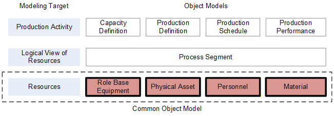
ISA-95 provides a standard manner to uniquely describe this information for exchange, including the interrelationships between the various types of information. The ISA-95 standard is described in multiple parts, where each part describes a portion of the standard. The 2010 versions of Parts 1 and 2 of the ISA-95 standard have been used to define a UA companion standard using OPC UA constructs for the purpose of exposing the ISA-95 objects and attributes in an OPC UA environment. This first release of the UA companion standard supports a subset of the entire ISA-95 standard, covering the role based equipment, physical asset, material and personnel object models in ISA-95 (see Figure 1). Later revisions of the companion standard may include support for the other ISA-95 object models such as process segment, operations definition, operations schedule, operations performance and operations capability object models.
4.2 ISA-95 Summary
4.2.1 Introduction
For an OPC UA user that may not be familiar with ISA-95, the following section provides a brief overview of key features that ISA-95 provides along with a little background related to ISA-95 and the concepts behind it.
4.2.2 Why ISA-95?
Typically in a manufacturing world plants optimize their control systems to maximize production and profits. Manufacturing companies must also be efficient at coordinating and controlling personnel, materials, and equipment across different control systems in order to reach their maximum potential. This coordination and control must occur in at least four different parts of an organization; production, quality tests and test labs, warehousing and inventory management, and maintenance.
This coordination and control is often supported by Manufacturing Execution Systems (MES) for management of production operations, Laboratory Information Management Systems (LIMS) for quality tests and test lab management, Warehouse Management Systems (WMS) or Tank Farm Management systems for management of inventory operations, and Asset Management or Computerized Maintenance Management Systems (CMMS) for maintenance operations. These systems together are collectively called Manufacturing Operations Management (MOM) systems. MOM defines a diverse set of functions that operate above automation control systems, reside below the level of enterprise business systems and are local to a site or area.
ISA-95 was created to allow efficient sharing and coordination of information between the various levels. The following subsections summarize the information that needs to be exchanged.
Sharing Material Information: Manufacturing requires materials. It is not surprising that manufacturing systems have a requirement to identify and track materials because the main purpose of manufacturing is to convert materials in one form into materials of another form. An important part of MOM integration is maintaining and exchanging material identification and information.
MES identify materials and their suitability for use, batch management systems confirm that the correct materials are used as specified in the recipes,
Tracking and tracing systems (bar-code scanners and RFID readers),
LIMS confirm that the correct materials are tested and the correct materials are used in testing,
WMS identify materials in their storage locations.
Shared material information can be divided into three main categories;
material class information identifies the materials without regard to the source of the material,
material definition information identifies material from specific vendors or sources,
material lot information identifies actual material, its location and quantity.
Sharing Equipment Information: One important element of managed information is the correct identification of the equipment used for manufacturing. Equipment identification is used for:
scheduling,
tracking and tracing,
maintenance,
troubleshooting,
visualization (HMI),
capacity tracking,
OEE (Overall Equipment Effectiveness) calculations.
Unfortunately, it is not uncommon for a manufacturing company to have multiple identifications for a single piece of equipment. Therefore, a critical aspect of equipment information management is managing different equipment ID's across multiple vendor systems and applications.
Sharing Physical Asset Information: Identification of a unique physical asset, irrespective of the role the equipment is performing is vital for:
maintenance,
equipment qualification and regulatory compliance,
financial asset tracking
While equipment is typically identified by a tag, such as TT-101 for a temperature transmitter, that identifies the role, or current function, of a specific asset physical asset information this is not sufficient for tracking individual assets for maintenance and financial purposes. To manage assets a company must have a unique identifier for the physical asset that is independent of the role it serves at a specific point in time. For example temperature transmitter TT-101 may have a serial number of X2 on a specific day, the next day the transmitter may be swapped out with a replacement transmitter with the same specifications but with the serial number X3. X3 would then be configured to have the tag TT-101 and X2 would no longer be known as TT-101. In order to track the transmitters X2 and X3 the physical asset information model would be used, while for operations purposes it is only important that TT-101 is in use and providing a temperature reading, the operators and control systems do not generally need to know the asset tag of TT-101, they just need the tag.
Tracking of individual physical assets allows companies to monitor individual asset's health records, ensure they are qualified for production and track them in financial systems.
Sharing Personnel Information: Multiple regulatory rules, laws, and internal procedures require that personnel who perform shop floor actions are unequivocally identified, are authorized to perform the actions, and have valid training or qualifications to perform the actions. Because personnel information is usually maintained in multiple IT systems and control systems, it is a key area of exchanged information. Specific uses in different systems that require coordination and sharing include:
MES Personnel qualification to be checked before someone is allowed to take an action
LIMS Identification of approved personnel to perform tests and handle materials, often based on their training qualifications,
AM Certification information about personnel performing maintenance activities to ensure that they have the proper training required by the activity,
WMS Certification that personnel are trained and qualified to handle material movement systems, such as fork trucks or crane systems.
4.2.3 ISA-95
The ISA-95 Enterprise/Control System Integration standard defines five levels of activities in a manufacturing organization. Generally, automation and control support Levels 1 and 2, MOM systems support Level 3, and business Enterprise Resource Planning (ERP) systems support Level 4 activities. The ISA-95 levels are shown in Figure 1.
Level 0 defines the actual physical processes.
Level 1 elements are the sensors and actuators attached to the control functions in automation systems.
Level 2 automation and control systems have real-time responses measured in sub-seconds and are typically implemented on Programmable Logic Controllers (PLC), Distributed Control Systems (DCS), and Open Control Systems (OCS).
Level 3 typically operates on time frames of days, shifts, hours, minutes, and seconds. Level 3 functions also include maintenance functions, quality assurance and laboratory functions, and inventory movement functions, and are collectively called Manufacturing Operations Management. A wide variety of systems support the activities, including SCADA (Supervisory Control and Data Acquisition) systems for monitoring the process and providing operator control, batch control systems for execution of recipes, data historians for the collection and preservation of time based data from Level 2 systems, recipe and document management systems for managing recipes and workflow instructions, detailed scheduling, campaign management or work dispatching, and work or product tracking.
Level 4 typically operates on time frames of months, weeks, and days. Enterprise Resource Planning (ERP) logistics systems are used to automate Level 4 functions. Level 4 is called Business Planning and Logistics.
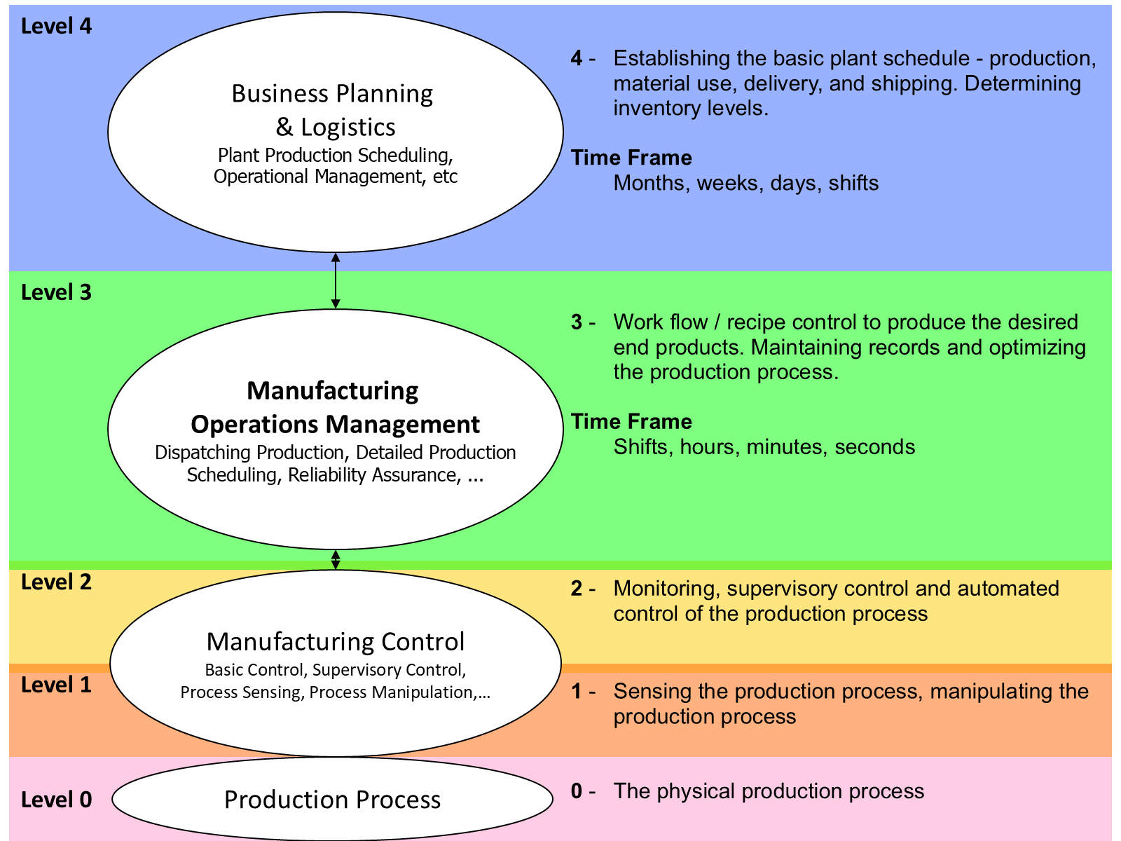
It is important to remember that each level has some form of control and each level has its own definition for real-time. Level 3 systems consider real-time to mean information available a few seconds after shop floor events occur. Level 4 systems consider real-time to mean that logistics and material information is available daily or within a few hours after the end of a shift.
ISA-95 typically deals with information exchange across Level 3 systems or between Level 3 and Level 4 systems. Specifically this would involve information exchange between ERP, EAM, CMMS, MES, WMS, LIMS, PLC and DCS systems. This information exchange in real-time is often required in order to allow workflows and recipes to execute in a timely manner. ISA-95 defines four primary types of information that often must be exchanged among MOM systems and between ERP systems and MOM systems, these types are; information about material and the properties of materials, information about equipment as it pertains to the operations being performed, information about the physical assets that make up the equipment, and information about personnel and their roles and qualifications.
4.2.4 Modelling Approach of ISA-95
The ISA-95 modelling approach to information is based on a "Property" model. [Note this is an ISA Property not a Property as defined by OPC UA] The ISA-95 models define a minimum set of industry-independent information as attributes. Industry specific, application specific, and company specific information are represented as property objects. For example, the personnel class property would be used to define application or industry specific attributes for personnel classes, and person property would be used to contain instance values for the properties.
In the ISA-95 resource models there are "Classes" and "Instances". The word "Class" used as part of an object definition name should be considered as a classification, not as a "Class" in the official UML Modelling definition. For example: "Personnel Class" should be considered a "Personnel Classification", because it is used to distinguish between the kinds of personnel in the real world and to define properties that would be common to personnel within the same classification. The UML description of each of the ISA Information models is described. The ISA-95 Model also includes definitions of common attributes. These definitions are not part of the UML figures, but are included as text in the ISA-95 specification.
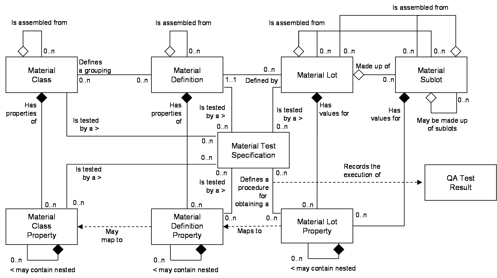
Material: is from ISA-95.00.02, it is the ISA-95 material object model. This is the definition of the lots, sublots, material definitions, and material classes involved in production. This information allows Level 3 and Level 4 systems to unambiguously identify material specified in production schedules and consumed or produced in actual production. A prime business driver for using the material model is to provide the ability to trace all materials used in the manufacture of a product to aide in quality analysis and product recalls.
Each Material Definition instance defines a type of material, such as Acetic Acid, grade 4. Each Material Definition may have specific properties, such as pH. These properties can be nested, in that a property can have its own properties. Material Definitions may be assembled from other Material Definitions, as in the case of a sub-assembly in car manufacturing, such as a transaxle which is identified as a Material Definition but is pre-assembled from multiple other Material Definitions. The sub-assembly record keeping is important to maintain traceability.
Material Definitions may belong to a Material Class. Material Classes are used as logical groups to manage Material definitions. Material Classes also have properties that can be nested and may also use the same assembly construct as used by Material Definitions.
Each Material Lot is an instance of a Material Definition that is uniquely identified. Material Lots also have properties that can be nested and may also use an assembly construct similar to that used by Material Definitions, the difference is that a Material Lot may be assembled from other Material Lots and/or Material Sublots. Material Lot instance properties are typically used to track specific shipments or orders of material.
Each Material Sublot is an instance of a Material Definition that is uniquely identified. Material Sublots do not have properties since each sublot instance must have the same properties as the Material Lot it is part of. Material Sublots may also use the same assembly construct as used by Material Lots. Material Sublot instances are typically used to provide tracking resolution within Material Lots, for example a Material Lot may have been received from a vendor in ten barrels, each barrel may be identified as a separate Material Sublot in order to track its movements and environmental conditions during storage and production.
The Material Test Specification identifies a test that may be associated with determining the value for a property of a Material Class, Material Definition or Material Lot instance. The information obtained from running the test can be modelled in the QA Test Result.
Personnel: Figure 2 is from ISA-95.00.02, it is the ISA-95 personnel object model. This is the definition of the persons and personnel classes (roles) involved in production. This information may be used to associate production with specific persons as part of a production record, or with personnel classes to allocate production costs.
Each instance of the Personnel Class from ANSI/ISA-95.00.02, is the Personnel object model. Each instance of the Personnel Class defines a role that a person can perform, such as a Draftsman. Each role may have specific properties, such as a Drafting License Number and a License Expiration Date. These Properties can also have their own nested properties. Each Person can be associated to one or more Personnel Class Roles. If the person is a Draftsman, then the Person Properties define the values for the Drafting License Number and License Expiration Date for that person. The Qualification Test Specification identifies a test that may be associated with determining the value for a property (such as a test for Draftsman used to obtain a Drafting License Number.) The information obtained from taking the test can be modelled in the Qualification Test Result.
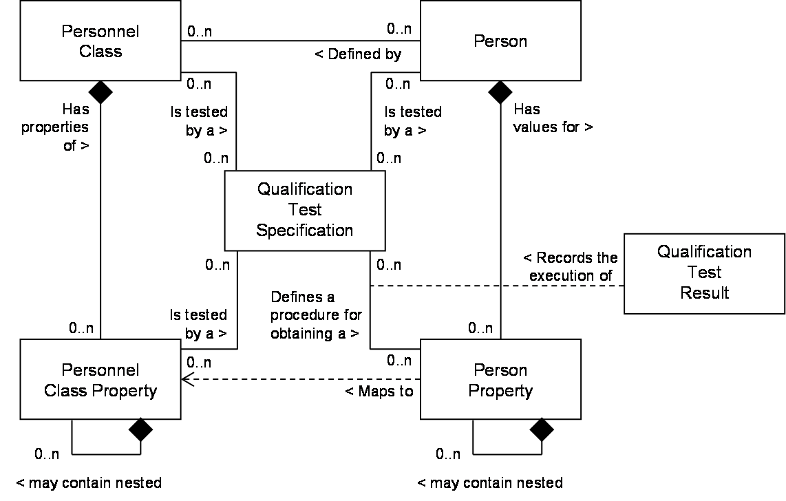
This modelling approach for ISA-95 means that properties must be able to be dynamically queried and browsed. The properties available for individual objects will be different, for example in Figure 22 - Personnel Overview, Joe Smith has a Drafting License Number, but Sally Jones does not.
Equipment: Figure 5 is, from ISA-95.00.02, it is the equipment object model. This is the definition of the roles that equipment and equipment classes perform in production, inventory management, and quality test labs. This information may be used to associate production with specific equipment as part of a production record, or with equipment classes to schedule production and allocate costs
Each instance of the Equipment Class defines a classification of equipment, such as a tank. Each Equipment Class may have specific properties, such as a volume. These properties can be nested, in that a property can have its own properties. Each piece of Equipment can be associated to one or more Equipment Classes. If the Equipment is a tank, then the Equipment Properties define the values for the volume of the tank. Equipment can also be nested, in that they can contain other Equipment. The tank may also include several sensors such as temperature. The modeller can choose between extra properties or next properties and nest equipment depending on their own criteria. The Equipment Capability Test Specification identifies a test that may be associated with determining the value for a property. The information obtained from running the test can be modelled in the Equipment Capability Test Result.
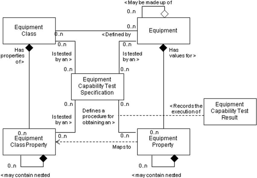
The Modelling approach for ISA-95 results in multiple levels of Equipment and Equipment Classes. By definition if an Equipment is defined by an Equipment Class then it will have Equipment Properties that correspond to the Equipment Class Properties in the defining Equipment Class.
Physical Assets: Figure 6 is from ISA-95.00.02, it is the physical asset object model. This is an identification of the specific physical asset (by serial number or asset ID) used in manufacturing operations. It also includes the make and model information that identifies the type of physical asset and its properties.
Each instance of the Physical Asset Class defines a classification of Physical Asset, such as a valve. Each class may have specific properties, such as a percent open. These properties can be nested, in that a property can have its own properties. Each Physical Asset is associated to one Physical Asset Classes. This relationship is more like a type of, for example a car would be a Porsche 911 Carrera S, and it could not also be any other model. If the Physical Asset is a car, then the Physical Asset Properties define the values for the colour of the car and maybe the option package associated with the car. The option package would have its own properties such as leather interior, sun roof etc.. Physical Assets can also be nested, in that they can contain other Physical Assets. For example a Car would contain four tires that have their own Physical Asset Class. The Physical Asset Capability Test Specification identifies a test that may be associated with determining the value for a property. The information obtained from running the test can be modelled in the Physical Asset Capability Test Result.
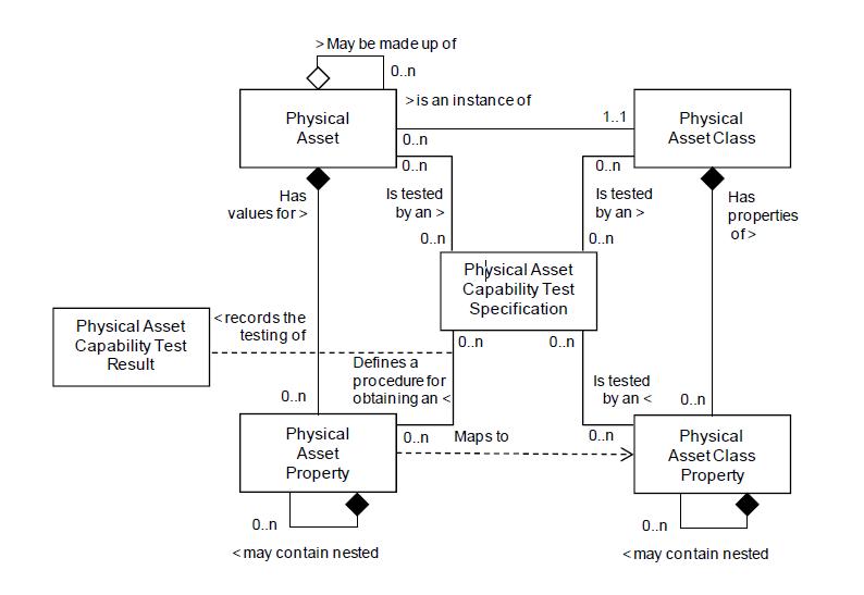
The Modelling approach for ISA-95 results in multiple levels of Physical Assets. By definition if a Physical Asset is defined by a Physical Asset Class then it will have Physical Asset Properties that correspond to the Physical Asset Class Properties in the defining Physical Asset Class.
4.2.5 Key Points
ISA-95 is an abstract specification in that it does not provide any implementation. Other organizations, such as MESA, have created an implementation (B2MML) of the ISA-95 standard. B2MML generated a mapping of the ISA-95 standard that is appropriate for the technology used in the mapping, but the mapping used does not in all cases map well to OPC UA. This specification generates a mapping based on the ISA-95 specification, and where possible it follows the B2MML mapping to allow an easier translation of a B2MML model to an OPC UA Model.
The ISA-95 Model also expects end users to generate a custom model that is based on the defined constructs. The resulting model contains a large amount of information and can require considerable time to develop. The ability to translate a B2MML model to an OPC UA model is an attempt to allow reuse of the extended effort to define a B2MML model.
4.3 OPC UA Summary
4.3.1 Introduction
For ISA-95 user that may not be familiar with OPC UA the following section provides a brief overview of key features that OPC UA provides.
4.3.2 What is OPC UA?
OPC UA is an open and royalty free set of standards designed as a universal communications protocol. While there are numerous communication solutions available, OPC UA has several advantages:
A state of art security model (see OPC 10000-2).
A fault tolerant communication protocol.
An information modelling framework that allows application developers to represent their data in a way that makes sense to them.
OPC UA has a broad scope which delivers for economies of scale for application developers. This means that a larger number of high quality applications at a reasonable cost are available. When combined with powerful semantic models such as ISA-95, OPC UA makes it easier for end users to access data via generic commercial application.
The OPC UA model is scalable from small devices to ERP systems. OPC UA devices process information locally and then provide that data in a consistent format to any application requesting data - ERP, MES, PMS, Maintenance Systems, HMI, Smartphone or a standard Browser, for examples. For a more complete overview see OPC 10000-1.
4.3.3 Basics of OPC UA
As an Open Standard, OPC UA is based on standard Internet technologies - TCP/IP, HTTP, Ethernet, and XML.
As an Extensible Standard, OPC UA provides a set of services (see OPC 10000-4) and a basic information model framework. This framework provides an easy manner for creating and exposing vendor defined information in a standard way. More importantly all OPC UA Clients are expected to be able to discover and use vendor defined information. This means OPC UA users can benefit from the economies of scale that come with generic visualization and historian applications. This specification is an example of an OPC UA Information Model designed to meet the needs of developers and users.
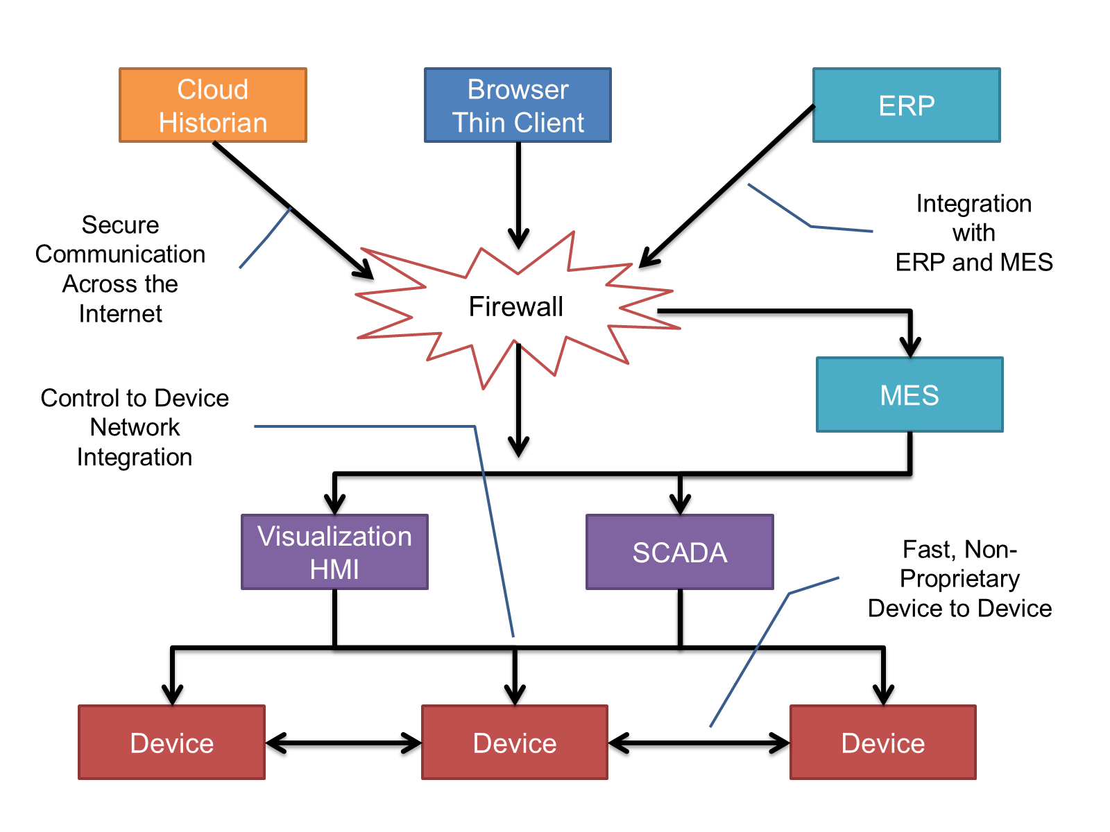
OPC UA Clients can be any consumer of data from another device on the network to browser based thin clients and ERP systems. The full scope of OPC UA applications are shown in Figure 7.
OPC UA provides a robust and reliable communication infrastructure having mechanisms for handling lost messages, failover, heartbeat, etc. With its binary encoded data it offers a high-performing data exchange solution. Security is built into OPC UA as security requirements become more and more important especially since environments are connected to the office network or the internet and attackers are starting to focus on automation systems
4.3.4 Information Modelling in OPC UA
4.3.4.1 Concepts
OPC UA provides a framework that can be used to represent complex information as Objects in an address space which can be accessed with standard web services. These Objects consist of Nodes connected by References. Different classes of Nodes convey different semantics. For example a Variable Node represents a value that can be read or written. The Variable Node has an associated DataType that can define the actual value, such as a string, float, structure etc. It can also describe the variable value as a variant. A Method Node represents a function that can be called. Every Node has a number of Attributes including a unique identifier called a NodeId and non-localized name called as BrowseName. An Object representing a 'Reservation' is shown in Figure 8.

Object and Variable Nodes are called Instance Nodes and they always reference a Type Definition (ObjectType or VariableType) Node which describes their semantics and structure. Figure 9 illustrates the relationship between an Instance and its Type Definition.
The Type Nodes are templates that define all of the children that can be present in an Instance of the Type. In the example in Figure 9 the PersonType ObjectType defines two children: First Name and Last Name. All instances of PersonType are expected to have the same children with the same BrowseNames. Within a Type the BrowseNames uniquely identify the child. This means Client applications can be designed to search for children based on the BrowseNames from the Type instead of NodeIds. This eliminates the need for manual reconfiguration of systems if a Client uses Types that multiple devices implement.
OPC UA also supports the concept of sub typing. This allows a modeller to take an existing Type and extend it. There are rules regarding sub typing defined in OPC 10000-3, but in general they allow the extension of a given type or the restriction of a DataType. For example the modeller may decide that the existing ObjectType in some cases needs an additional variable. The modeller can create a Subtype of the object and add the variable. A client that is expecting the parent type can treat the new Type as if it was of the parent Type. With regard to DataTypes, if a variable is defined to have a numeric value, a sub type could restrict the Value to a float.

References allow Nodes to be connected together in ways that describe their relationships. All References have a ReferenceType that specifies the semantics of the relationship. References can be hierarchical or non-hierarchical. Hierarchical references are used to create the structure of Objects and Variables. Non-hierarchical are used to create arbitrary associations. Applications can define their own ReferenceType by creating Subtypes of the existing ReferenceType. Subtypes inherit the semantics of the parent but may add additional restrictions. Figure 10 depicts several references connecting different Objects.

The figures above use a notation that was developed for the OPC UA specification. The notation is summarized in Figure 11. UML representations can also be used; however, the OPC UA notation is less ambiguous because there is a direct mapping from the elements in the figures to Nodes in the address space of an OPC UA server.
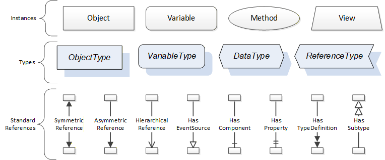
A complete description of the different types of Nodes and References can be found in OPC 10000-3 and the base OPC UA Address space is described in OPC 10000-5.
OPC UA specification defines a very wide range of functionality in its basic information model. It is not expected that all Clients or Servers support all functionality in the OPC UA specifications. OPC UA includes the concept of profiles, which segment the functionality into testable certifiable units. This allows the development of companion specification (such as OPC UA for ISA-95) that can describe the subset of functionality that is expected to be implemented. The profiles do not restrict functionality, but generate requirements for a minimum set of functionality (see OPC 10000-7)
The OPC Foundation also defines a set of information models that provide a basic set of functionality. The Data Access specification (see OPC 10000-8) provides a basic information model for typical data. The Alarm and Condition specification (see OPC 10000-9) defines a standard information model for Alarms and Conditions. The Programs specification (see OPC 10000-10) defines a standard information model for extending the functionality available via method calls and state machines. The Historical Access specification (see OPC 10000-11) defines the information model associated with Historical Data and Historical Events. The aggregates specification (see OPC 10000-13) defines a series of standard aggregate functions that allow a Client to request summary data. Examples of aggregates include averages, minimums, time in state, Standard deviation, etc.
4.3.4.2 Namespaces
OPC UA allows information from many different sources to be combined into a single coherent address space. Namespaces are used to make this possible by eliminating naming and id conflicts between information from different sources. Namespaces in OPC UA have a globally unique string called a NamespaceUri and a locally unique integer called a NamespaceIndex. The NamespaceIndex is only unique within the context of a Session between an OPC UA Client and an OPC UA Server. All of the web services defined for OPC UA use the NamespaceIndex to specify the Namespace for qualified values.
There are two types of values in OPC UA that are qualified with Namespaces: NodeIds and QualifiedNames. NodeIds are globally unique identifiers for Nodes. This means the same Node with the same NodeId can appear in many Servers. This, in turn, means Clients can have built in knowledge of some Nodes. OPC UA Information Models generally define globally unique NodeIds for the TypeDefinitions defined by the Information Model.
QualifiedNames are non-localized names qualified with a Namespace. They are used for the BrowseNames of Nodes and allow the same Names to be used by different information models without conflict. The BrowseName is used to identify the children within a TypeDefinitions. Instances of a TypeDefinition are expected to have children with the same BrowseNames. TypeDefinitions are not allowed to have children with duplicate BrowseNames; however, Instances do not have that restriction.
4.3.4.3 Companion Specifications
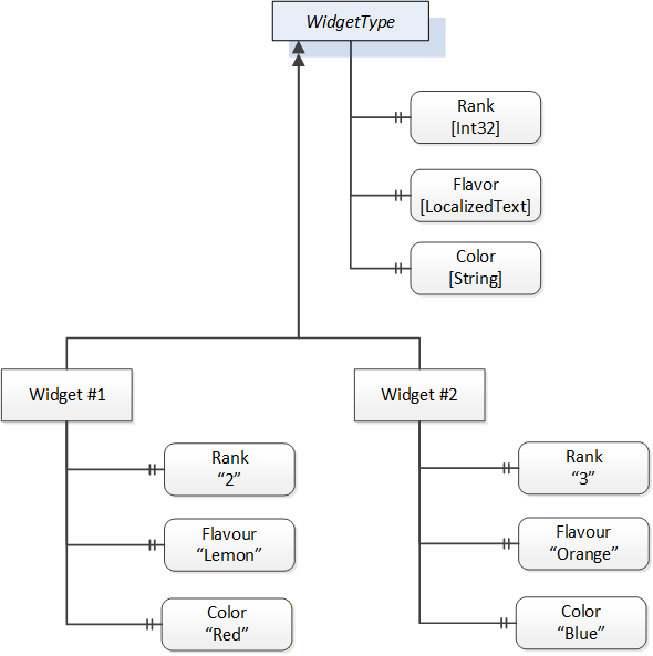
An OPC UA companion specification for an industry specific vertical market describes an information model by defining ObjectTypes, VariableTypes, DataTypes and ReferenceTypes that represent the concepts used in the vertical market. Table 1 contains an example of an ObjectType definition.
| Attribute | Value | ||||
| BrowseName | WidgetType | ||||
| IsAbstract | False | ||||
| Reference | NodeClass | BrowseName | DataType | TypeDefinition | ModellingRule |
|---|---|---|---|---|---|
| Subtype of the BaseObjectType from OPC 10000-5. | |||||
| HasProperty | Variable | Color | String | PropertyType | Mandatory |
| HasProperty | Variable | Flavor | LocalizedText | PropertyType | Mandatory |
| HasProperty | Variable | Rank | Int32 | PropertyType | Mandatory |
The BrowseName is a non-localized name for an ObjectType.
IsAbstract is a flag indicating whether instances of the ObjectType can be created.
The bottom of the table lists the child nodes for the type. The Reference is the type of reference between the Object instance and the child Node. The NodeClass is the class of Node. The BrowseName is the non-localized name for the child. The DataType is the structure of the Value accessible via the Node (only used for Variable NodeClass Nodes) and the TypeDefinition is the ObjectType or VariableType for the child.
The ModellingRule indicates whether a child is Mandatory or Optional. It can also indicate cardinality. Note that the BrowseName is not defined if the cardinality is greater than 1. Figure 12 visually depicts the ObjectType defined in Table 1 along with two instances of the ObjectType.
4.4 Modelling Approach of ISA-95
The modelling approach for generating an UA model from an existing ISA-95 follows the following general concepts / suggestions.
Review the ISA-95 model documentation.
Map all ISA95 properties to OPC UA Variables and OPC UA VariableTypes, creating OPC UA VariableTypes as needed. Create a subtype of a VariableType whenever the item will be reused multiple times; otherwise just create an instance of the appropriate OPC UA VariableType (Equipment Property Type or PhysicalAssetPropertyType ….).
Map all ISA Classes and ISA Objects to OPC UA ObjectTypes, creating OPC UA ObjectTypes as needed. Again ObjectType need only be created for Objects where multiple instance of the Object will exist, otherwise simply creating an instance of the appropriate ObjectType (EquipmentType, PhysicalAssetType).
Create all types as part of a hierarchical set of types, to allow for easier implementation and maintenance.
Convert IDs that are used to indicate a relationship between ISA-95 Model items to OPC UA References. Use the References defined in this specification as needed. Generate Custom References only if an existing reference does not exist, and the Reference provides some unique semantic information.
Reuse existing OPC UA concepts wherever possible, such as Descriptions, Names, EngineeringUnits etc. These items should not be duplicated as additional ISA properties.
Compare any resulting model to the B2MML model for the same concept. This comparison is to ensure that no concepts were misunderstood or modelled very differently. The goal does include being able to transform a UA model into B2MML and also to transform B2MML Models into UA Models. The two models do not need to be identical, but they need to be transformable.