
1 Scope
This document provides a comprehensive overview of the Application and Use Cases defined in the OPC UA Companion Specification Mining. As explained in OPC 40560, this document contains definitions and descriptions of the Application and Use Cases defined by the Specialist Working Groups for machines and systems participating in longwall operation.
2 Normative references
The following documents are referred to in the text in such a way that some or all of their content constitutes requirements of this document. For dated references, only the edition cited applies. For undated references, the latest edition of the referenced document (including any amendments and errata) applies.
OPC 10000-1, OPC Unified Architecture - Part 1: Overview and Concepts
OPC 10000-1
OPC 40560, OPC Unified Architecture for Mining - General
http://opcfoundation.org/UA/Mining/General/
3 Terms, definitions and conventions
3.1 Overview
It is assumed that basic concepts and motivations of OPC UA information modelling from OPC 10000-1 are understood in this document. This document will describe the abstract Application Case Longwall Operation and its constituent Use Cases. These have been developed by a Specialist Working Group and serve as a base for the OPC UA information models of machines and systems taking part in longwall operations.
3.2 Abbreviated Terms
| AC | Application Case AFC Armored Face Conveyor FAS Face Alignment System RSS Roof Support System UC Use Case |
3.3 Conventions used in this document
For a definition and example of the terms of 'Application Case' and 'Use Case', please refer to OPC 40560.
4 Application and Use Cases of OPC 40569-1: Longwall Operation
4.1 Application Case Longwall Operation
The Application Case Longwall Operation is composed of all defined and modelled Use Cases for longwall mining operations. The detailed descriptions and diagrams of each Use Case may be found in Chapter 0 of this document. Table 1 contains information regarding the chapter number of each Use Case within the Application Case Longwall Operation and the involved equipment. The rows contain the different equipment types used within the Use Cases, which are displayed in the columns.
| Use Cases → | Initializa-tion | Shield Advance | PushAFC | Conveying | Anti- Collision | Face-Alignment | Horizon-Control |
|---|---|---|---|---|---|---|---|
| Equipment ↓ | |||||||
| Shearer |
4.2.1 | 4.2.2 | 4.2.3 | 4.2.4 | 4.2.5 | 0 | 4.2.7 |
| AFC | |||||||
| RSS | 4.2.2 | 4.2.3 | 4.2.5 | 0 | 4.2.7 | ||
| FAS |
4.2 Use Cases for the AC Longwall Operation
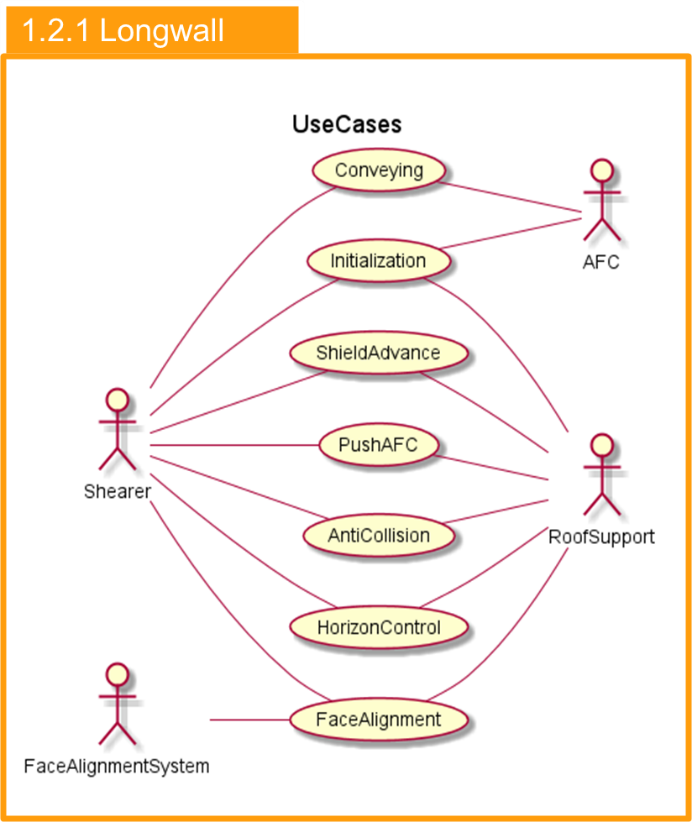
The Application Case Longwall Operation is composed of the Use Cases for underground longwall mining systems. Figure 1 presents the Application Case "Longwall" including the Use Cases "Conveying", "Initialization", "Shield Advance", "Push AFC", "Anti-Collision" "Horizon Control" and "Face Alignment". Furthermore, the involved Users, which are the "Shearer", "AFC", "RoofSupport" and "Face Alignment System are displayed in Figure 1 as well.
4.2.1 Use Case Initialization
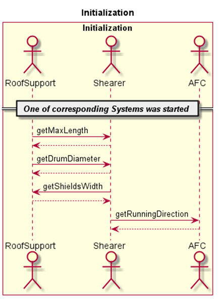
The Initialization UC is utilized for the initial exchange of system dimensions or non-mutable data between the communication partners. It is mandatory and needs to be run every time the connection to one of the partners is (re-)established. Figure 2 shows the sequence diagram of the Initialization use case.
4.2.2 Use Case Shield Advance
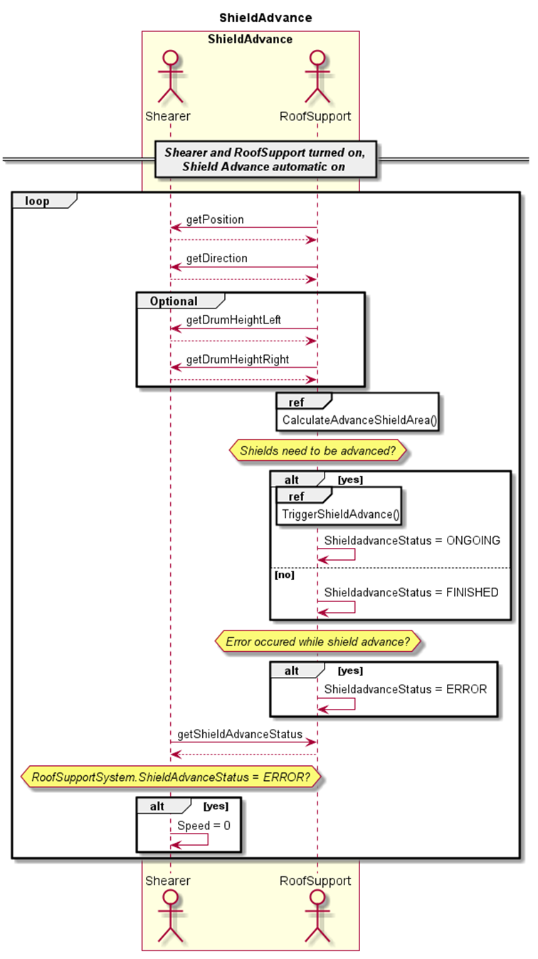
The Shield Advance UC describes the process of moving shields towards the coal face depending on the Shearer's position.
The Roof Support System cyclically reads the position and the running direction of the Shearer. By taking the Shearer's position and dimensions and the actual position of the shields into account, the Roof Support System calculates which shields shall be pulled. The Roof Support System advances the corresponding shields, if necessary. This state is reflected by setting the ShieldadvanceStatus-Variable to ONGOING. Once the shield advance action is finished, i.e. all shields are in the desired position, ShieldadvanceStatus is set to FINISHED.
If necessary and applicable, the Shearer can use the Roof Support System's ShieldadvanceStatus in its automation states.
For advanced operation, the Shearer's drum heights can be used by the Roof Support System to determine the desired shield positions, if shield advance above the machine body is allowed. Figure 3 contains the sequence diagram of this UC.
4.2.3 Use Case Push AFC
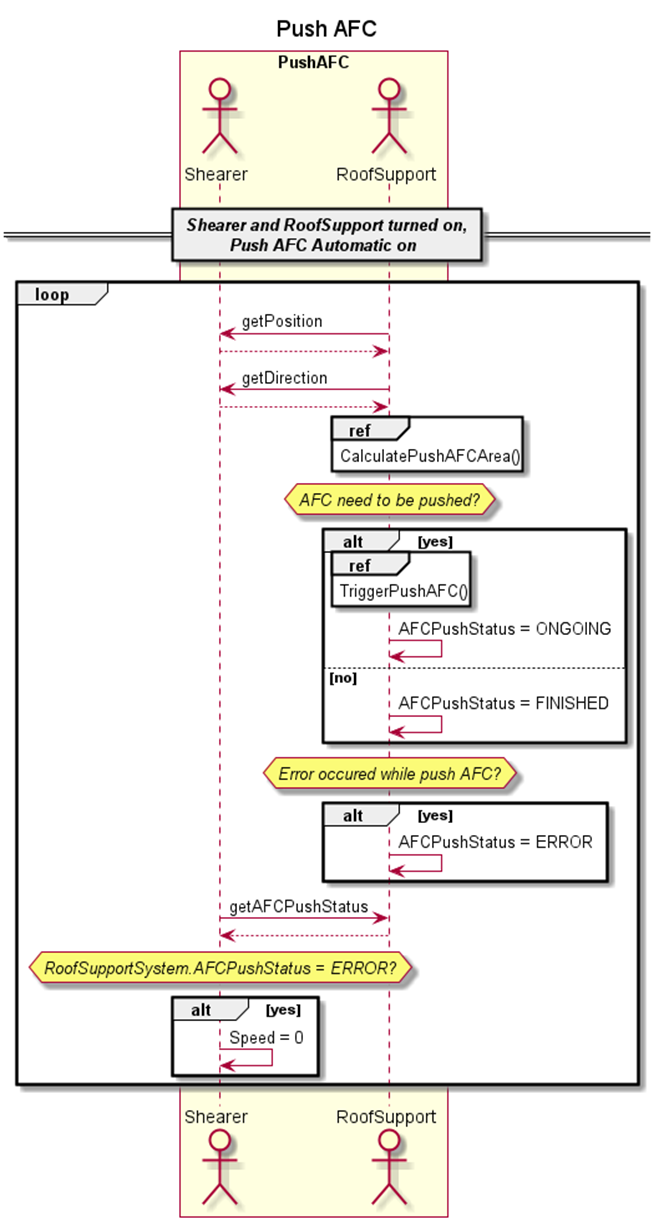
This Push AFC UC describes the process of pushing the AFC towards the coal face depending on the Shearer's position.
The Roof Support System cyclically reads the position and the running direction of the Shearer. By taking the Shearer's position and dimensions and the actual position of the AFC sections into account, the Roof Support System calculates which sections shall be pushed. The Roof Support System advances the corresponding sections, if necessary. This state is reflected by setting the AFCPushStatus to ONGOING. If the AFC has successfully advanced all sections (i.e. all sections are in the desired position), the AFCPushStatus is set to FINISHED. The Shearer can use the AFC's AFCPushStatus in its automation states if necessary. Figure 4 illustrates the sequence diagram of this UC.
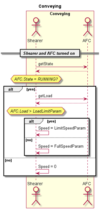
4.2.4 Use Case Conveying
The Conveying UC describes the automatic adaption of the Shearer's speed depending on the AFC's load.
The Shearer cyclically reads the State of the AFC. If the AFC's State is RUNNING, the Shearer reads the Load-Variable from the AFC. If the AFC's Load exceeds a parameterizable threshold, the Shearer's speed is limited to a certain value. For advanced operation, the AFC's Load can be used for a linear increase of the Shearer's maximum speed. Figure 5 displays the sequence diagram of this UC.
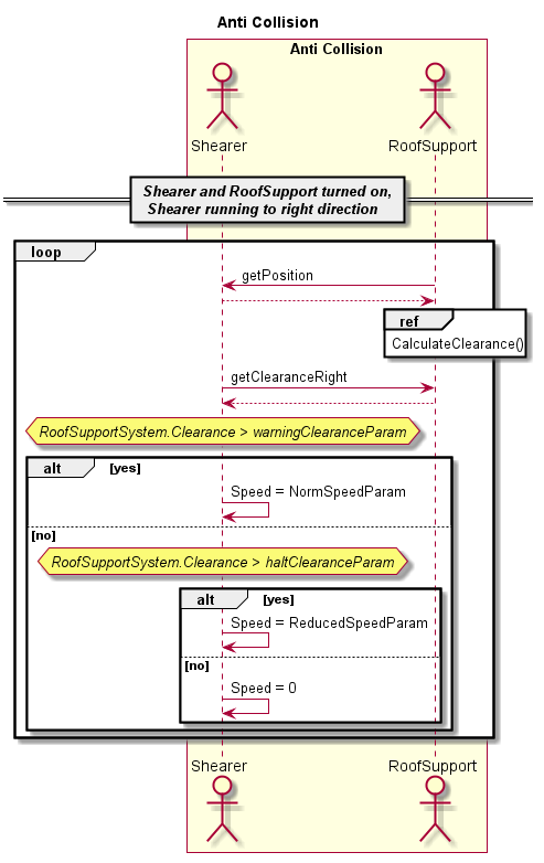
4.2.5 Use Case Anti-Collision
The Anti-Collision UC describes the automated process of preventing collisions between the Shearer cutting drums and the Roof Support Shields. The Shearer receives information about the clear area and is responsible for decreasing speed or stopping before a collision would occur.
The Roof Support System cyclically reads the Shearer's position. By taking the Shearer's position, dimensions and the actual position of the shields into account, the Roof Support System calculates clearance values for each side of the machine (ClearanceLeft and ClearanceRight). These values reflect the area, in which it is safe for the shearer to move. The values are based on the Shearer's center of machine.
Depending on the current project/mine, the clearance values will be determined in different ways and will include different factors. Depending on the application, the Roof Support System can check sensor values of flipper, forepole canopy, setting pressure and advance ram.
The Shearer cyclically reads the clearance value for the current movement direction (ClearanceLeft or ClearanceRight) and reduces its maximum speed, if the clearance is below a warning threshold, or even stops, if it is lower than a halt threshold.
For advanced operation, the Roof Support System's clearance can be used for a linear increase of the Shearer's maximum speed. Figure 6 displays the sequence diagram of this UC.
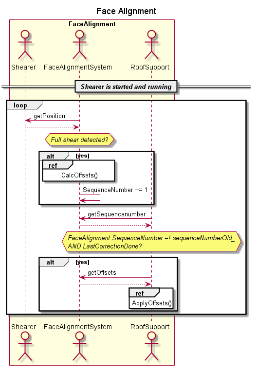
4.2.6 Use Case Face Alignment
The Face Alignment UC describes the automated process for straightening the conveyor line respective to an aerial view.
The Face Alignment System cyclically reads the Shearer's position for determining the completion of a full shear. If a full shear was detected, the Face Alignment System uses its measurements to calculate offset values for each shield. After the calculation is finished, the Face Alignment System increases its SequenceNumber.
The Roof Support System cyclically reads the SequenceNumber of the Face Alignment System. If a new SequenceNumber was detected, the Roof Support System reads the new calculated offsets from the Face Alignment System and applies these offsets for the next shear. Figure 7 contains the sequence diagram of this UC.
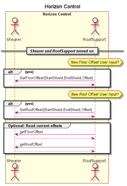
4.2.7 Use Case Horizon Control
The Horizon Control UC describes the process of manually correcting the cutting heights to optimize coal extraction and reduce rock cutting in specific areas. The operator uses the Roof Support System's control panel to send correction data to the shearer.
If a new user input for either the roof or the floor offset is done, the Roof Support System sends the offset for the corresponding area (identified by StartShield and EndShield) to the Shearer.
The Shearer uses these offsets for controlling the arm heights in the next shear. Optionally, the Roof Support System can read the present FloorOffset and RoofOffset of all shields from the Shearer to allow the user to see the currently applied values. Figure 8 contains the sequence diagram of this UC.
___________
Agreement of Use
COPYRIGHT RESTRICTIONS
This document is provided "as is" by the OPC Foundation and VDMA.
Right of use for this specification is restricted to this specification and does not grant rights of use for referred documents.
Right of use for this specification will be granted without cost.
This document may be distributed through computer systems, printed or copied as long as the content remains unchanged and the document is not modified.
OPC Foundation and VDMA do not guarantee usability for any purpose and shall not be made liable for any case using the content of this document.
The user of the document agrees to indemnify OPC Foundation and VDMA and their officers, directors and agents harmless from all demands, claims, actions, losses, damages (including damages from personal injuries), costs and expenses (including attorneys' fees) which are in any way related to activities associated with its use of content from this specification.
The document shall not be used in conjunction with company advertising, shall not be sold or licensed to any party.
The intellectual property and copyright is solely owned by the OPC Foundation and VDMA.
PATENTS
The attention of adopters is directed to the possibility that compliance with or adoption of OPC or VDMA specifications may require use of an invention covered by patent rights. OPC Foundation or VDMA shall not be responsible for identifying patents for which a license may be required by any OPC or VDMA specification, or for conducting legal inquiries into the legal validity or scope of those patents that are brought to its attention. OPC or VDMA specifications are prospective and advisory only. Prospective users are responsible for protecting themselves against liability for infringement of patents.
WARRANTY AND LIABILITY DISCLAIMERS
WHILE THIS PUBLICATION IS BELIEVED TO BE ACCURATE, IT IS PROVIDED "AS IS" AND MAY CONTAIN ERRORS OR MISPRINTS. THE OPC FOUDATION NOR VDMA MAKES NO WARRANTY OF ANY KIND, EXPRESSED OR IMPLIED, WITH REGARD TO THIS PUBLICATION, INCLUDING BUT NOT LIMITED TO ANY WARRANTY OF TITLE OR OWNERSHIP, IMPLIED WARRANTY OF MERCHANTABILITY OR WARRANTY OF FITNESS FOR A PARTICULAR PURPOSE OR USE. IN NO EVENT SHALL THE OPC FOUNDATION NOR VDMA BE LIABLE FOR ERRORS CONTAINED HEREIN OR FOR DIRECT, INDIRECT, INCIDENTAL, SPECIAL, CONSEQUENTIAL, RELIANCE OR COVER DAMAGES, INCLUDING LOSS OF PROFITS, REVENUE, DATA OR USE, INCURRED BY ANY USER OR ANY THIRD PARTY IN CONNECTION WITH THE FURNISHING, PERFORMANCE, OR USE OF THIS MATERIAL, EVEN IF ADVISED OF THE POSSIBILITY OF SUCH DAMAGES.
The entire risk as to the quality and performance of software developed using this specification is borne by you.
RESTRICTED RIGHTS LEGEND
This Specification is provided with Restricted Rights. Use, duplication or disclosure by the U.S. government is subject to restrictions as set forth in (a) this Agreement pursuant to DFARs 227.7202-3(a); (b) subparagraph (c)(1)(i) of the Rights in Technical Data and Computer Software clause at DFARs 252.227-7013; or (c) the Commercial Computer Software Restricted Rights clause at FAR 52.227-19 subdivision (c)(1) and (2), as applicable. Contractor / manufacturer are the OPC Foundation, 16101 N. 82nd Street, Suite 3B, Scottsdale, AZ, 85260-1830
COMPLIANCE
The combination of VDMA and OPC Foundation shall at all times be the sole entities that may authorize developers, suppliers and sellers of hardware and software to use certification marks, trademarks or other special designations to indicate compliance with these materials as specified within this document. Products developed using this specification may claim compliance or conformance with this specification if and only if the software satisfactorily meets the certification requirements set by VDMA or the OPC Foundation. Products that do not meet these requirements may claim only that the product was based on this specification and must not claim compliance or conformance with this specification.
TRADEMARKS
Most computer and software brand names have trademarks or registered trademarks. The individual trademarks have not been listed here.
GENERAL PROVISIONS
Should any provision of this Agreement be held to be void, invalid, unenforceable or illegal by a court, the validity and enforceability of the other provisions shall not be affected thereby.
This Agreement shall be governed by and construed under the laws of Germany.
This Agreement embodies the entire understanding between the parties with respect to, and supersedes any prior understanding or agreement (oral or written) relating to, this specification.