This clause defines network services needed for the operation of UAFX and their remote management (see 7.2). Network services defined in this document's release include topology discovery (see 7.3) and time synchronisation (see 7.4).
This subclause defines remote management for UAFX Stations for networking features, including those defined in Clause 6, as well as the services and capabilities defined in Clause 7. For interoperable remote management, UAFX uses the Network Configuration Protocol (NETCONF) as a remote management protocol (see 7.2.2).
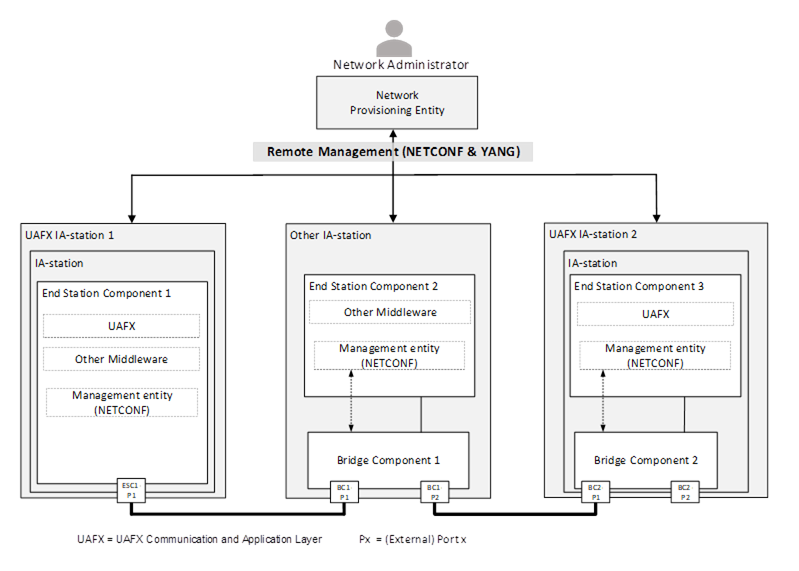
Figure 15 – Network commissioning using NETCONF and YANG
Figure 15 shows an example network consisting of two UAFX Stations and one IA-station. The Network Provisioning Entity uses NETCONF as the common remote management protocol for network configuration during commissioning (see OPC 10000-80, Figure 6) as required for the site. This configuration may contain, amongst others, VLAN configuration, IP subnet configuration, time synchronisation configuration, and QoS configuration. In addition, remote management enables network monitoring and communication fault diagnostics.
A UAFX Station supporting remote management shall support a Network Configuration Protocol (NETCONF) server as defined in IETF RFC 7589 (NETCONF over TLS).
NOTE 1 This document does not make use of SSH as a secure transport for NETCONF.
NOTE 2 A future release of this document will define NETCONF capabilities (for both client and server) and YANG modules to be supported by a UAFX Station.
A single management entity controls all components of a UAFX Station. Figure 16 shows a UAFX Station comprised of two End Station Components and one Bridge Component, all controlled by a single management entity.
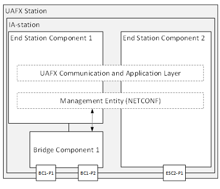
Figure 16 – Example of a UAFX Station supporting NETCONF
NETCONF messages are recommended to be transmitted using priority information defined for Remote Management in Table 1.
UAFX defines the use of LLDP for the discovery of IA-stations, their external ports, and their external connectivity (see 7.3.2). A Topology Discovery Entity (TDE) queries this information by remote management to derive the physical network topology and provide it to a System Engineer (see Figure 17).
NOTE A Topology Discovery Entity (TDE) can be run from anywhere in the network with reachability to the to-be-discovered devices.
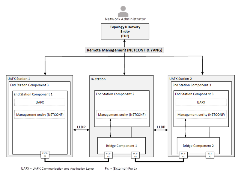
Figure 17 – Example of a TDE querying LLDP information from two UAFX Stations and an IA-station
UAFX defines the use of the LLDP protocol for IA-stations to announce themselves to their peers for device and topology discovery. By default, announcements from a UAFX Station contain, among others, the management address(es) and system capabilities (see 7.3.2.2.4).
For adaptability of the operational behaviour and the announced information of LLDP, all UAFX Stations support the LLDP local system YANG (see 7.3.2.2.5). UAFX Stations that include a Bridge Component also receive and store LLDP announcement information received from their peers in the LLDP remote systems YANG.
A remote management protocol (see 7.2) is used between the TDE and IA-stations to query the local system YANG and remote systems YANG. The management address information in the retrieved remote systems YANG allows the TDE to discover and query new IA-stations. The correlation of an IA-station’s local system data with a neighbouring IA-station’s remote systems data enables the TDE to discover the physical network topology.
Figure 18 illustrates an example network showing the LLDP agents and their management in a UAFX Station consisting of a single End Station Component, an IA-station, and a UAFX Station with an End Station Component and a Bridge Component.
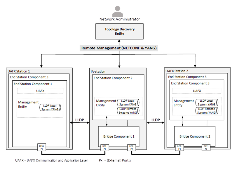
Figure 18 – Usage example of LLDP in UAFX
A UAFX Station shall implement LLDP according to IEEE Std 802.1AB-2016, 5.3, following the definitions in 7.3.2.2.
LLDP defines several operational parameters that control the protocol behaviour (see IEEE Std 802.1AB2016, 10.5.1). These parameter definitions apply to all external ports of a UAFX Station.
NOTE According to IEEE Std 802.1AB2016, 9.1.1 c), changes to the local system that impact information exchanged via LLDP immediately trigger the transmission of an LLDPDU to communicate the local changes as quickly as possible to any neighbouring systems.
A UAFX Station shall support LLDP transmit mode (adminStatus enabledTxOnly) on an external End Station Component port and may support transmit and receive mode (adminStatus enabledRxTx) on that port (see IEEE Std 802.1AB-2016, 10.5.1).
A UAFX Station shall support LLDP transmit and receive mode (adminStatus enabledRxTx) on an external Bridge Component port (see IEEE Std 802.1AB-2016, 10.5.1).
The destination address shall be the nearest bridge group MAC address, i.e. 01-80-C2-00-00-0E, to limit the scope of LLDPDU propagation to a single physical link (see IEEE Std 802.1AB2016, 7.1 item a).
It is recommended that LLDPDUs be transmitted using the traffic class associated with Network Control as defined in Table 1 and derived from 6.4.3.
NOTE IEEE 802.1AB-2016 defines LLDPDUs to be transmitted untagged, i.e., frames do not carry priority information for traffic class selection. At the same time, IEEE 802.1AB-2016 neither specifies a well-defined device-internal priority nor management capabilities for the configuration of the traffic class to be used for the transmission of LLDPDUs.
A UAFX Station transmitting LLDPDUs shall include the LLDP TLVs selected in this sub-clause. A UAFX Station receiving LLDPDUs shall process LLDPDUs and include the information in the LLDP Remote System’s YANG.
Each transmitted LLDPDU shall contain the following LLDP TLVs defined in IEEE 802.1AB-2016, 8.5:
- exactly one Chassis ID TLV, as defined in 7.3.2.2.4.2,
- exactly one Port ID TLV, as defined in 7.3.2.2.4.3,
- exactly one Time To Live TLV,
- exactly one System Capabilities TLV, as defined in chapter 7.3.2.2.4.4,
- one or more Management Address TLVs, as defined in 7.3.2.2.4.5, and
- zero or more additional TLVs not listed in this requirement.
NOTE The concatenation of the Chassis ID and Port ID fields enables the recipient of an LLDPDU to identify the sending LLDP agent/port.
The Chassis ID field shall contain the same value for all transmitted LLDPDUs independent from the transmitting port of the UAFX Station, i.e., be a non-volatile, UAFX Station-unique identifier.
The Chassis ID subtype field should contain subtype 4, indicating that the Chassis ID field contains a MAC address to achieve the Chassis ID's desired deployment-wide uniqueness. For UAFX Stations with multiple unique MAC addresses, any one of the UAFX Station’s MAC addresses may be used and shall be the same for all external ports of that UAFX Station.
The Port ID field shall contain the same value for all transmitted LLDPDUs for a given external port, i.e., be a non-volatile, UAFX Station-unique identifier of the LLDPDU-transmitting port.
The Port ID subtype field should contain subtype 5, indicating that the Port ID field contains the interface name (name) according to IETF RFC 8343.
A UAFX Station consisting of only one or more End Station Components shall set the system and enabled capabilities fields to Station Only (i.e., bit 8 set to “1”) for all transmitted LLDPDUs.
A UAFX Station with at least one End Station Component and at least one Bridge Component shall set the system and enabled capabilities fields to Station Only (i.e., bit 8 set to “1”) and C-VLAN component (i.e., bit 9 set to “1”) for all transmitted LLDPDUs.
NOTEThe combination of the Station Only and C-VLAN component flags is used as a marker indicating to the TDE that the internal structure of the UAFX Station consists of multiple components. This is a deliberate deviation from a footnote in IEEE Std 802.1AB2016, Table 8-4.
A UAFX Station supporting remote management shall announce at least one IPv4 address by which its management entity (see 7.2.2) can be reached.
A UAFX Station supporting remote management (see 7.2) shall implement LLDP management according to IEEE 802.1ABcu-2021, 5.3 Item o).
A UAFX Station supporting the remote systems YANG shall be able to store information from at least one neighbour per external port. Receiving LLDPDUs from more neighbours than supported on a given port shall result in the last one received being saved to the remote systems YANG as described in IEEE Std 802.1AB2016, 9.2.7.7.5.
UAFX defines the use of a time synchronisation protocol to ensure a common sense of time among participating IA-stations.
UAFX defines the use of gPTP as defined in IEEE Std 802.1AS2020 for the time synchronisation of UAFX Stations. Figure 19 illustrates an exemplary time-synchronised network with two gPTP domains (see 7.4.2.1.1). The usage of an application clock as ClockSource or ClockTarget depends on the IEEE Std 802.1AS defined role for synchronisation. Each instance of ClockSource or ClockTarget is bound to one PTP Instance. The number and type of PTP Instances residing on a UAFX Station depend on the gPTP domains it participates in and its composition, e.g., the presence of a Bridge Component. A UAFX Station can host more than one PTP Instance, e.g., UAFX Stations 1 and 2. A Grandmaster PTP Instance can reside on any grandmaster-capable UAFX Station, e.g., UAFX Station 3. UAFX Station 2 and IA-station support the forwarding of corrected time information in both gPTP domains via PTP Relay Instances (see 7.4.2.1.2).
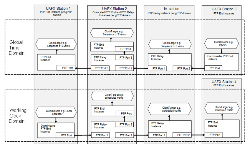
NOTE The extent of the Working Clock domain and the Global Time domain may differ.
Figure 19 – Usage example of Global Time and Working Clock domains in UAFX.
The gPTP generates a tree-structure clock relationship between PTP Instances in the network. The clocks in all PTP Instances within a gPTP domain derive their time from a clock known as the Grandmaster Clock.
The following subclauses provide further informative descriptions of IEEE Std 802.1AS2020 terminology and how it applies to UAFX.
IEEE Std 802.1AS2020 defines a gPTP domain in which system timing is consistent. A gPTP domain defines the scope of gPTP message communication, state, operations, parameters, and timescale. The Grandmaster PTP Instance is the root of a gPTP domain.
UAFX supports the following two types of gPTP domains:
Working Clock domain maintains a common sense of time for use cases such as enhancements for scheduled traffic (see IEEE Std 802.1Q).
Global Time domain (e.g. wall clock) maintains a common sense of time across an industrial automation network for use cases such as sequence of events.
There are two types of PTP Instances used in a gPTP domain:
A PTP Instance operates in a single Bridge Component or End Station Component within exactly one gPTP domain. A UAFX Station can contain more than one PTP Instance in the same gPTP domain (see 7.4.2.1.4).
PTP Instances interface with the communications network using logical entities called PTP Ports.
A UAFX Station can support one or more gPTP domains. Each gPTP domain is represented by a PTP Instance, which can have an associated ClockSource or ClockTarget. A PTP Instance with an associated ClockSource is a Grandmaster PTP Instance. A ClockSource and ClockTarget can serve as a provider of time for a UAFX Application (e.g., sequence of events).
Figure 20 shows an example of a UAFX Station consisting of a single End Station Component supporting one gPTP domain. Figure 21 shows an example of a UAFX Station consisting of a single End Station Component supporting two gPTP domains. Each gPTP domain has an associated PTP End Instance, which connects via a PTP Port to an Ethernet port.
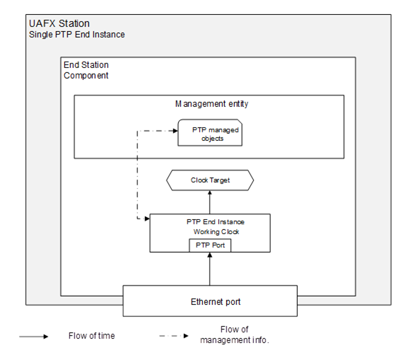
Figure 20 – UAFX Station example with one PTP End Instance
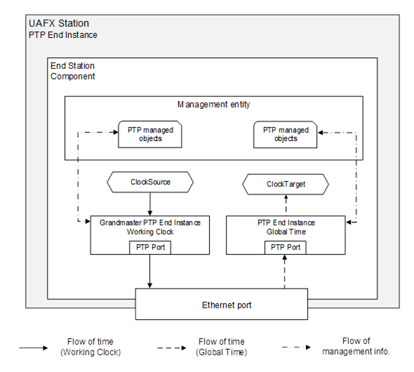
Figure 21 – UAFX Station example with two PTP End Instances
Figure 22 shows an example of a UAFX Station consisting of a single End Station Component and Bridge Component, each supporting two gPTP domains. This example includes Bridge Component ClockTargets and End Station Component PTP End Instances and ClockTargets for both domains. ClockTargets and PTP End Instances may be omitted in an implementation depending on the expected usage of time.
NOTE How PTP messages are internally dispatched between the PTP Relay Instance and the PTP End Instance is implementation-dependent.
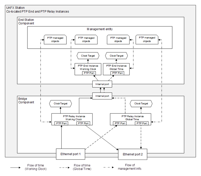
Figure 22 – UAFX Station example with PTP End and PTP Relay Instances
Engineered time synchronisation spanning tree (sync tree) for a given gPTP domain refers to the usage of external port configuration instead of BMCA to construct a desired sync tree with the Grandmaster PTP Instance as the root (see IEEE Std 802.1AS2020, 10.3.1).
One of the advantages of engineered sync trees is to enable a planned, deterministic, and stable configuration of the IEEE Std 802.1AS2020 sync tree for a given gPTP domain, e.g., prevent sync tree changes in case of UAFX Station addition or removal from the network. Working Clock is a use case of the engineered sync tree.
The Grandmaster PTP Instance resides in a dedicated Grandmaster-capable IA-station.
An external sync tree management entity should use the remote management interface described in clause 7.4.2.2.4 to set up an engineered sync tree.
The following configuration is used for all PTP Ports intended to participate in a gPTP domain using an engineered time synchronisation spanning tree:
- The externalPortConfigurationEnabled parameter is set to TRUE;
- The ptpPortEnabled parameter is set to TRUE.
For validation that the computed sync tree configuration can be applied to all PTP Ports intended to participate in the given gPTP domain, the management entity configuring the sync tree will, for example, verify that these ports are up, IEEE Std 802.1AS2020-capable, and satisfy topology constraints by checking the following parameters:
- The status of oper-status parameter is up (see IETF RFC 8343) for all participating Ethernet links;
- The status of isMeasuringDelay (see IEEE Std 802.1AS2020, 14.16.4) parameter is TRUE;
- The status of asCapable (see IEEE Std 802.1AS2020, 14.8.7) is TRUE;
- The status of asCapableAcrossDomains (see IEEE Std 802.1AS2020, 14.16.5);
- The status of gmCapable (see IEEE Std 802.1AS2020, 14.2.7) is TRUE, only applicable to the Grandmaster PTP Instance;
- Verify that the number of PTP Relay Instances (hops) between the Grandmaster PTP Instance and any given PTP End Instance is within the limit prescribed by an external sync tree management entity;
- Verify per PTP link that the value of meanLinkDelay (see IEEE Std 802.1AS2020, 14.16.6) is less than or equal to meanLinkDelayThresh (see IEEE Std 802.1AS2020, 14.16.7 and IEEE Std 802.1AS2020 Table 11-1) value to detect, e.g., an anomaly in propagation delay;
NOTE Even if neighbouring PTP Instances do report asCapable, it can be that the link between asCapable neighbouring PTP Instances is not asCapable due to, for example, the wrong setting of meanLinkDelayThresh value. The meanLinkDelayThresh value reflects the estimated propagation delay of the installed link.
The sync tree needs to have the following properties to ensure consistent protocol behaviour and time synchronisation:
- The desiredState of all PTP Ports of the Grandmaster PTP Instance is set to MasterPort;
- The desiredState of exactly one PTP Port of all the other PTP Instances is set to SlavePort;
- The desiredState of remaining PTP Ports that are part of sync tree in non-Grandmaster PTP Relay Instances is set to MasterPort.
- The desiredState of all other PTP Ports is set to PassivePort.
After synthesis, the configuration of the gPTP domain and its engineered sync tree may then be applied and validated, for example:
Set Sync message transmission interval uniformly, e.g., default interval.
Set PTP Port states according to synthesis for all PTP Instances.
Check that the syncLocked (see IEEE Std 802.1AS2020, 14.8.52) parameter is TRUE for all PTP Ports of PTP Relay Instances in MasterPort state.
A UAFX Station supporting gPTP time synchronisation as defined in IEEE Std 802.1AS2020 shall conform to IEEE Std 802.1AS2020, 5 with the definitions specified in 7.4.2.2.2, 7.4.2.2.3, and 7.4.2.2.4.
NOTE Clocks are currently not modelled in OPC UA, and it is a vendor decision to select a gPTP domain for use at the application layer if multiple gPTP domains are supported. Clock representation in OPC UA needs to be added in a future release for UAFX.
A UAFX Station supporting gPTP time synchronisation shall support at least two gPTP domains in a Bridge Component for Working Clock and Global Time and at least one gPTP domain in an End Station Component for Working Clock or Global Time.
The gPTP message priority is defined in IEEE Std 802.1AS2020, 8.4.4.
It is recommended that gPTP messages are transmitted using the traffic class associated with Network Control as defined in Table 1 and derived from 6.4.3.
NOTE IEEE Std 802.1AS2020 defines gPTP messages to be transmitted untagged, i.e., frames do not carry priority information for traffic class selection. At the same time, IEEE Std 802.1AS2020 neither specifies a well-defined device-internal priority nor management capabilities for the configuration of the traffic class to be used for the transmission of gPTP messages.
A UAFX Station supporting remote management (see 6.2) and gPTP time synchronisation shall implement gPTP management for the managed objects defined in IEEE Std 802.1AS2020, 14.
Bibliography
IEEE Std 1588-2019 – Precision Clock Synchronization Protocol for Networked Measurement and Control Systems
https://standards.ieee.org/standard/1588-2019.html
OPC 10000-84, OPC Unified Architecture – Part 84: UAFX Profiles
http://www.opcfoundation.org/UA/Part84/
IEC/IEEE 60802 – Time-Sensitive Networking Profile for Industrial Automation
https://1.ieee802.org/tsn/iec-ieee-60802/
OPC 1000083, OPC Unified Architecture – Part 83: UAFX OfflineEngineering
http://www.opcfoundation.org/UA/Part83/
OPC 10000-100, OPC Unified Architecture – Part 100: Devices
http://www.opcfoundation.org/UA/Part100/
IETF RFC 4594 – Configuration Guidelines for DiffServ Service Classes, August 2006
https://www.rfc-editor.org/rfc/pdfrfc/rfc4594.txt.pdf
IETF RFC 3246 – An Expedited Forwarding PHB (Per-Hop Behavior), March 2002
https://www.rfc-editor.org/rfc/pdfrfc/rfc3246.txt.pdfhttps://www.rfc-editor.org/rfc/pdfrfc/rfc3246.txt.pdf
IETF RFC 8343 – A YANG Data Model for Interface Management, March 2018
https://www.rfc-editor.org/rfc/pdfrfc/rfc8343.txt.pdf
IEEE Std 802.1AS-2011 – IEEE Standard for Local and Metropolitan Area Networks – Timing and Synchronisation for Time-Sensitive Applications in Bridged Local Area Networks
https://standards.ieee.org/standard/802_1AS-2011.html
IEEE Draft Std P802.1ASdn – Draft Standard for Local and Metropolitan Area Networks: Timing and Synchronisation for Time-Sensitive Applications – Amendment: YANG Data Model
https://1.ieee802.org/tsn/802-1asdn/
IETF RFC 6762 – Multicast DNS
https://www.rfc-editor.org/rfc/pdfrfc/rfc6762.txt.pdf
____________