
5 OPC UA FX Information Model concepts
5.1 Overview
OPC UA provides the concepts for standard communication between Servers and Clients as well as Publishers and Subscribers, but additional concepts are required for OPC UA FX. These concepts include Connection establishment and bidirectional communication. The establishment of Connections further requires concepts such as identity and compatibility verification of Asset and FunctionalEntity, establishing control via ControlGroup selection, setting ConfigurationData, and communication configuration. These concepts are mapped to existing OPC UA communication models and are provided by the OPC UA FX Information Model. This clause conceptually describes the functionality provided in the overview of the Objects defined by the OPC UA FX Information Model.
5.2 Identity and compatibility verification
5.2.1 Overview
In an industrial automation system, device identity and compatibility refer to the process and mechanisms used to check that AutomationComponents (e.g., controllers, drives, IO devices) in a system allow operation that is consistent or compatible with what was expected by system engineering.
It is a common practice that various properties of communicating AutomationComponents are verified to check that:
AutomationComponents present in a system are either consistent with system engineering (i.e., match expectations);
their communication interfaces and exhibited application behaviour are compatible with system engineering expectations.
There are several scenarios where the verification of various properties of an AutomationComponent is utilised in an automation system:
ensuring that AutomationComponents match system engineering expectations during commissioning or initiating communication (e.g., detecting missing Assets like IO modules in a modular IO system);
replacing or updating an AutomationComponent or any of its subcomponents.
Identity and compatibility verification can be done at any time (and executed by any AutomationComponent or tool that knows expected properties and their values) as long as the AutomationComponents can be accessed via Client Server services. In an automation system, verification is typically done before AutomationComponents participate in the industrial control application or process. It is crucial to ensure that the participating AutomationComponents will supply output data (to a consuming AutomationComponent) and use the input data (from a producing AutomationComponent) in an expected way.
This document defines verification modes and a verification Method for Assets, which provides the possibility to verify an Asset’s identity and whether or not it performs at a level that is compatible with what is expected by system engineering. For FunctionalEntities, a verification Method is defined, which can be used to verify instance-specific properties (e.g., identity properties) to ensure that they are consistent with what is expected by system engineering.
The subsequent clauses provide the general concepts for identity and compatibility verification.
5.2.2 Asset verification
5.2.2.1 Overview
Asset verification provides functionality to verify whether a given Asset’s type and instance information match or are compatible with what was expected by system engineering.
Applicable use cases include:
commissioning an automation system (e.g., a machine) to ensure all Assets in an engineered system are from the expected manufacturer and are the expected model;
prior to or at the initiation of data communication between AutomationComponents to ensure nothing has been (adversely) changed (e.g., during maintenance or shutdown);
after conducting a firmware update to ensure the updated Asset is compatible with what was engineered;
after replacing an Asset to ensure that the Asset has been replaced by one that is compatible or identical to what was engineered;
verification of the instance of an Asset (e.g., serial number), which is often a requirement in certain applications and industries (e.g., pharmaceutical).
5.2.2.2 Asset identity
Asset identity refers to an Asset’s properties that make unambiguous identification possible. The IAssetRevisionType VerifyAsset Method provides the possibility to verify an Asset’s identity. See 6.3.3 for a detailed description.
5.2.2.3 Asset compatibility
This clause introduces the concept of Asset compatibility, which allows an Asset to report if it is compatible with what was expected by system engineering.
An important use case is AutomationComponent replacement. If an identical replacement (same manufacturer, model, and firmware) is unavailable, the vendor could be shipping a compatible substitute with updated hardware or firmware.
Asset compatibility verification provides functionality to verify whether a specific Asset’s properties match or are compatible (e.g., a newer firmware that is backwards compatible) with what was expected by system engineering.
Knowledge about Asset (and/or firmware) compatibility typically only exists with the vendor of a specific Asset. Thus, compatibility can only be determined by vendor-specific tools or a vendor’s Asset.
The IAssetRevisionType VerifyAsset Method, combined with the AssetVerificationModeEnum AssetCompatibility, allows verifying an Asset’s compatibility; see 6.3.3 for a detailed description.
5.2.3 FunctionalEntity verification
FunctionalEntity verification ensures that a given FunctionalEntity conforms to what was expected by system engineering. This verification includes checking the FunctionalEntity’s author, identifier, or version (issued by the author of a FunctionalEntity). It also supports checking any Variables defined by the application.
It can include checking, for instance, specific additional properties (e.g., the existence and values of optional properties that can represent the configuration of optional functionality or whether a FunctionalEntity is part of a specific application).
The IFunctionalEntityType Verify Method provides the possibility to verify instance-specific properties of a FunctionalEntity; see 6.4.3 for a detailed description.
5.3 ControlGroups
A FunctionalEntity can support multiple operating modes or groupings of functionality. An example might be a simple PID function block that supports cascade. In non-cascade mode, an HMI can set a setpoint, but the ability to externally set the setpoint is blocked in cascade. ControlGroups allow a FunctionalEntity to advertise these different groupings or modes.
A FunctionalEntity might define multiple (even nested) ControlGroups. These ControlGroups might be mutually exclusive, or they might be concurrently active. A ControlGroup might be related to just part of the functionality exposed by a FunctionalEntity.
Selecting a ControlGroup for control will often result in the locking of configuration or restricted access to ConfigurationData as defined by the FunctionalEntity (when the ControlGroup was defined). ControlGroups expose what restriction would occur if the given ControlGroup were selected for control. Locking can restrict access to Variables or Methods to a specific application/user. It can also just block all access to Variables or Methods. What occurs with the selection of a ControlGroup is defined as part of the ControlGroup. For example, all changes to some configuration parameters might need to be blocked as long as communication is occurring, or all changes to some configuration parameters might need to be restricted to a specific application. Any ControlGroup can reference any Variable / Method, and multiple ControlGroups might reference the same Variable / Method.
The ControlGroup provides a standard mechanism to configure what would be restricted or blocked, and with what application or functionality the restriction/block is associated. ControlGroups might be configured by product vendors and be related to the functionality provided by the AutomationComponent (e.g., a drive vendor or function block library vendor). It could also be defined by a system integrator that defines an application that will be using the FunctionalEntity.
5.4 ConfigurationData
ConfigurationData describes a collection of Variables within a FunctionalEntity that are used to set up and configure its functionality. As part of establishing a Connection between FunctionalEntities, some configuration might be required. This configuration is separate from the configuration required for the actual communication. The EstablishConnections Method allows any of the FunctionalEntity’s ConfigurationData to be set.
ConfigurationData can contain Variables that have the AccessLevelEx Attribute NonVolatile bit set to TRUE (see OPC 10000-3). After a power cycle, such Variables are initialised to the last value written before the power cycle.
OPC UA FX defines the concept of the storage of Variables (see 6.4.6). Variables that do not have the AccessLevelEx Attribute NonVolatile bit set can be configured to be part of the storage and are initialised to the stored value following a power cycle.
Variables that are not stored and do not have the AccessLevelEx Attribute NonVolatile bit set have an unspecified value (e.g., vendor-specific value) after a power cycle.
It is up to the provider of the FunctionalEntity whether to provide NonVolatile ConfigurationData or to support storage of Variables.
5.5 Logical connections
5.5.1 Overview
The logical functionality of an AutomationComponent is represented by one or more FunctionalEntities described in 4.4. An important part of the functional model is the data exchange between FunctionalEntities using logical connections. Figure 8 illustrates this interaction.
A logical connection is represented by two ConnectionEndpoints, one on each FunctionalEntity that is part of the connection. Figure 28 provides a more detailed view of the Objects involved.
Logical connections are configured using ConnectionConfigurationSets.
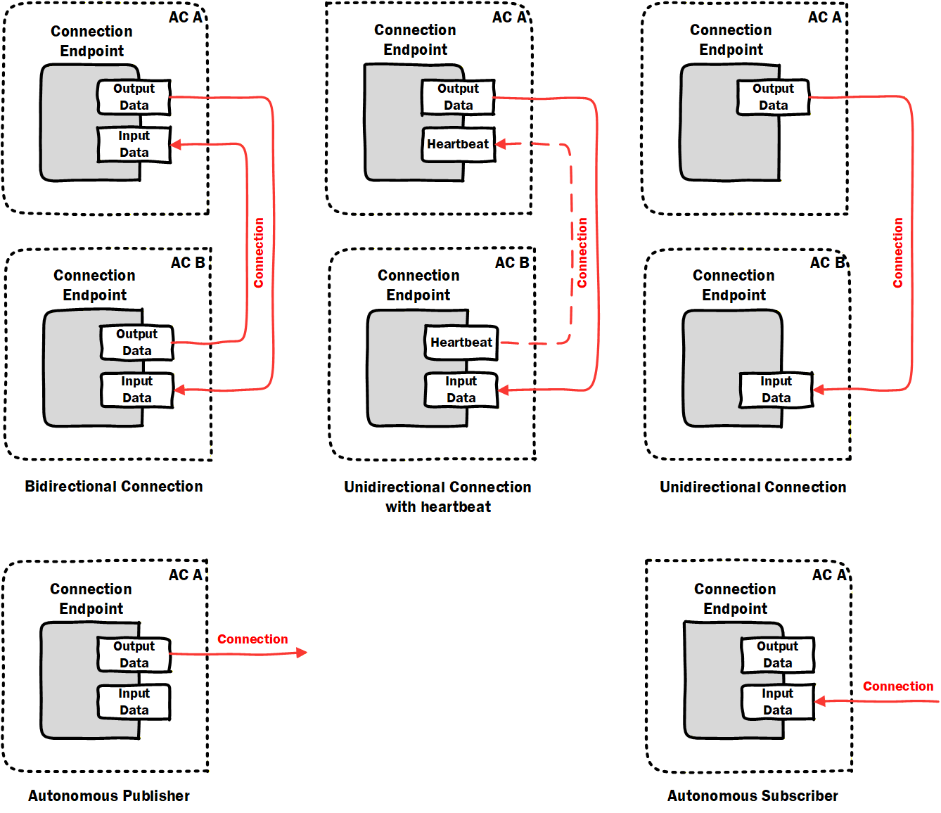
The following types of logical connections are supported (see Figure 10):
Bidirectional connections describe bidirectional data exchange between two FunctionalEntities.
Unidirectional connections with heartbeat describe unidirectional data exchange in one direction and a heartbeat message (for logical connection monitoring) in the opposite direction between two FunctionalEntities.
Unidirectional connections describe unidirectional data exchange between two FunctionalEntities.
Autonomous publisher describes data published by a FunctionalEntity, where the related subscribing ConnectionEndpoint(s) are unknown to the logical connection.
Autonomous subscriber describes data subscribed by a FunctionalEntity, where the related publishing ConnectionEndpoint(s) are unknown to the logical connection.
Auditing reports problems and changes triggered by an external application. A subscription within a Connection is considered a source of data (for source of data, see OPC 10000-4). Changes in the values of Variables from a data source do not generate AuditEvents.
5.5.2 Generation, deployment, and modification
This document defines the required data model for logical connection configuration information, represented by the ConnectionConfigurationSetType and additional ObjectTypes it utilises.
The ConnectionManagerType (see 6.7) exposes configuration information related to the establishment of logical connections. The configuration information is typically generated by an engineering tool based on offline or online information.
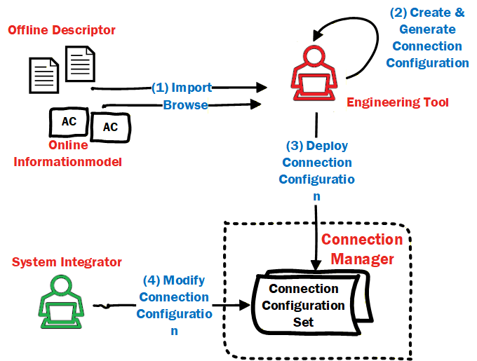
OfflineEngineering (see OPC 10000-83) offers the concept of Descriptors that describe the AutomationComponents; see Figure 11, label 1. Using these Descriptors or retrieving information online from the AutomationComponents, application engineers use vendor-specific engineering tools to generate the configuration data for logical connections (see Figure 11, label 2). All configuration data represented by one or more logical connections is defined in a ConnectionConfigurationSet. The instances can also include configuration information for the utilised OPC UA communication model (e.g., PubSub or Client Server [future]).
The engineering tool and ConnectionManager could reside on separate devices or be located on the same device.
ConnectionConfigurationSets can be deployed to the ConnectionManager (see Figure 11, label 3) using functionality defined in Annex F or vendor-specific means.
A ConnectionConfigurationSet can allow changes. For example, addressing information that is only available at commissioning time or communication-related properties like the PublishingInterval for data exchange can be modified by a system integrator. The changes that can be made can be restricted by the generator of the ConnectionConfigurationSet. The ConnectionManager exposes the ConnectionConfigurationSets (see 6.86.8), representing sets of logical connections to be established. Using generic tools (Clients), the ConnectionConfigurationSets can be modified as restricted (see Figure 11, label 4).
The ConnectionManager provides optional Methods to interact with these sets of logical connections, i.e., for editing and committing updates to sets (see 6.7.4) and to trigger processing (establishment for all logical connections) of sets (see 6.7.5). The ConnectionManager can also provide vendor-specific means.
5.5.3 Establishing and closing Connections
As introduced in 4.7, logical connection establishment can be executed by a ConnectionManager. If present on a Server, the ConnectionManager is represented in the Information Model by a well-known instance of ConnectionManagerType (see 6.7). To start the establishment of logical connections, the ConnectionManager could be triggered by vendor-specific means or by a Client using the ProcessConnectionConfigurationSets Method. It could also be an application that is always executing. The ConnectionManager calls the EstablishConnections Method on the AutomationComponents to establish the logical connections.
For each logical connection to be established, the ConnectionConfigurationSet includes:
address information, e.g., Server address, BrowsePath to the AutomationComponent, FunctionalEntity, etc.,
optional parameters to be used for verifying the Assets and FunctionalEntities,
optional parameters to be used for establishing control,
optional parameters to be used for configuring the application behaviour,
the definition of the data to be exchanged via the logical connection,
communication model-specific properties for the utilised OPC UA communication model (e.g., PubSub or Client Server [future]).
For more details on the ConnectionConfigurationSetType, see 6.8. For details on ConnectionManager functionality, see 6.7.
The ConnectionManager could be triggered to close logical connections by vendor-specific means or by a Client invoking the ProcessConnectionConfigurationSets Method. The ConnectionManager calls the CloseConnections Method on the AutomationComponents to close the logical connections.
5.5.4 Cleaning up Connections
5.5.4.1 Overview
A consumer of data can always detect data loss (e.g., caused by loss of network communication or a faulty producer), but in many industrial control applications, it is of interest to the application producing the data whether the consumer(s) of that data are still available. OPC UA FX provides a configurable clean-up of logical connections and all associated resources.
5.5.4.2 Operation
The lifetime of a logical connection on an AutomationComponent can be tied to its Status (see 6.6.2), which is, in turn, tied to the reception of data or heartbeat messages. A configurable CleanupTimeout (see 6.6.2) allows the deletion of all resources allocated to a specific ConnectionEndpoint once its status indicates loss of data reception.
This revision of the specification supports logical connections that utilise the PubSub communication model and hence builds on the usage of either DataSetMessages or heartbeat messages (see OPC 10000-14).
5.5.5 Persistent and preconfigured objects
Establishing logical connections can involve creating several Objects within the AutomationComponents.
Persistence refers to the ability of AutomationComponents to store configuration, which allows these Objects to be restored after a power cycle or other restart. Individual logical connections can be marked for persistence (see IsPersistent in 6.6.2).
An AutomationComponent can provide preconfigured Objects (e.g., PublishedDataSet or ConnectionEndpoint). An example might be a FunctionalEntity that includes a preconfigured PublishedDataSet that is used as part of a logical connection. The other parts of the logical connection (e.g., ConnectionEndpoint, WriterGroup, DataSetWriter) are all created during connection establishment. If the Connection is not marked for persistence, the other parts are deleted on clean-up or on a power cycle, and the preconfigured Objects will remain.
5.5.6 Relationship to OPC UA communication models
5.5.6.1 Overview
Connections between FunctionalEntities are designed to exchange data by utilising OPC UA communication models. This revision of the specification supports the PubSub communication model as defined in OPC 10000-14. Future revisions will support the Client Server communication model.
5.5.6.2 PubSub
5.5.6.2.1 Overview
This clause illustrates how Connections utilise the PubSub communication model, focusing on three use cases relevant in the context of industrial automation and the design of AutomationComponents. These are just illustrations, and additional or different uses might also apply. The grey-blue boxes in these illustrations are defined in this document, while the yellow blocks are defined in OPC 10000-14.
5.5.6.2.2 Single Connection using unicast network messages
This use case, illustrated in Figure 12, describes a single logical connection between two FunctionalEntities located on the AutomationComponents A and B, each containing a Publisher, a Subscriber, and a single PubSubConnectionEndpoint. Both FunctionalEntities could be publishing data (bidirectional Connection), or only one could be publishing data while the other publishes a heartbeat (unidirectional connection with heartbeat).
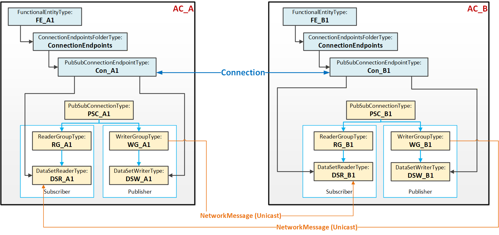
Figure 12 illustrates the logical connection between the two FunctionalEntities FE_A1 and FE_B1. Each FunctionalEntity contains a PubSubConnectionEndpoint (Con_A1 and Con_B1), which references a DataSetReader and a DataSetWriter.
The PubSub instances are configured to exchange data between AutomationComponents AC_A and AC_B using unicast NetworkMessages.
5.5.6.2.3 Multiple Connections using unicast network messages
This use case, illustrated in Figure 13, typically applies to AutomationComponents that host multiple FunctionalEntities and/or nested FunctionalEntities.
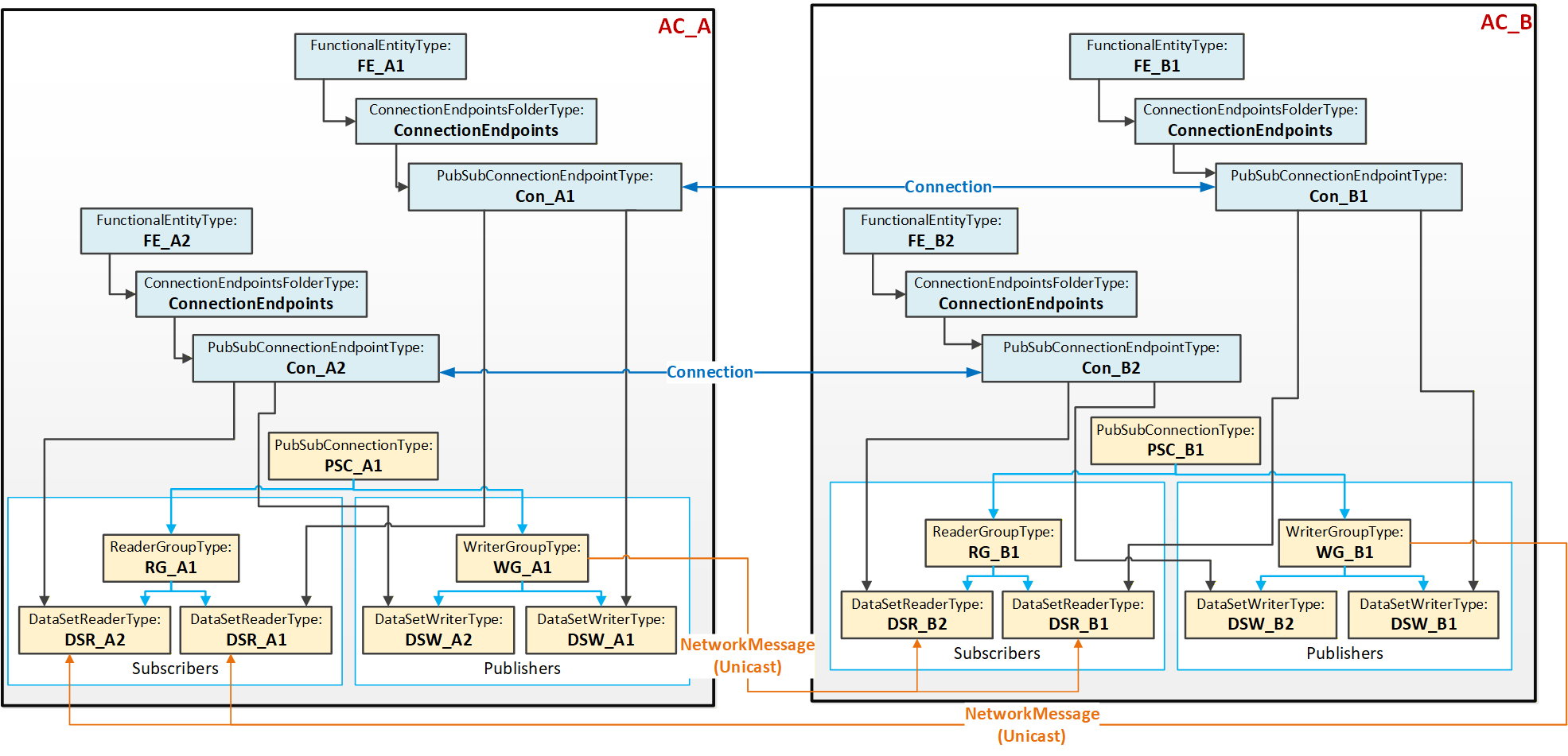
Figure 13 illustrates two Connections, each between two PubSubConnectionEndpoints. Each PubSubConnectionEndpoint on AC_A (and similarly on AC_B) references a DataSetWriter (and DataSetReader) that is located under the same WriterGroup (and ReaderGroup).
The PubSub instances are configured to exchange data between AC_A and AC_B using unicast NetworkMessages. This use case is called aggregated because a single NetworkMessage aggregates multiple DataSetMessages (one per logical connection). Aggregation reduces the required network bandwidth.
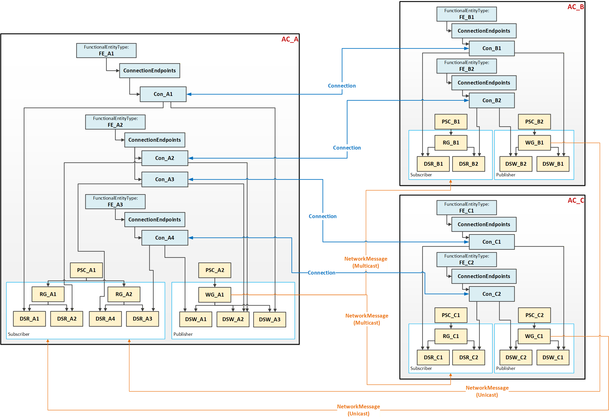
5.5.6.2.4 Multiple Connections using multicast network messages
This use case, illustrated in Figure 14, could be applied to an AutomationComponent (AC_A) communicating with multiple AutomationComponents (AC_B and AC_C). To minimise network bandwidth usage in specific topologies, AC_A can aggregate published data into a single NetworkMessage, which is sent via multicast to the associated AutomationComponents AC_B and AC_C. In turn, AC_B and AC_C publish an individual NetworkMessage back to AC_A. Multicast can also help with scaling issues in the device (less processing of network messages is required).
5.5.6.2.5 DataSetMetaData
Connections are configured by an engineering tool on behalf of Descriptors and are deployed to a ConnectionManager (see 5.5.2). Independent of the lifetime of a Connection, another engineering tool can update a FunctionalEntity, including its preconfigured DataSets. In addition, the Descriptor can describe a different version of the FunctionalEntity to be connected at runtime. This can result in misinterpretation of the exchanged data.
To prevent this error scenario, PubSub provides the DataSetMetaData. DataSetMetaData describes the content and semantics of a DataSet. In addition, the DataSetMetaData provides the details defining the contract between the Publisher and the Subscriber, including how to encode and decode the DataSetMessage. Thus, Subscribers must know about the PublishedDataSet’s DataSetMetaData. For the concepts of the DataSetMetaData and its definition, see OPC 10000-14.
Any change to a PublishedDataSet regarding its content but also its semantics (e.g., engineering units) would generate changes to its DataSetMetaData, indicated by a change in its ConfigurationVersion (see OPC 10000-14). Depending on the chosen UADP header layout, the ConfigurationVersion of an individual Publisher or a GroupVersion combining the ConfigurationVersions of all Publishers belonging to a WriterGroup is transmitted with the NetworkMessage. Any mismatch between the transmitted version and the one configured at the Subscriber will cause the Subscriber to go into Error. To resolve the Error, the Subscriber needs an update of the DataSetMetaData. OPC 10000-14 offers multiple ways to accomplish this.
5.6 Health
Assets, FunctionalEntities, ConnectionEndpoints, and ConnectionConfigurationSets provide general health status and diagnostic conditions. This health status is aggregated from child objects to parent objects (e.g., from ConnectionEndpoints to the FunctionalEntity, from FunctionalEntities to the AutomationComponent, or from ConnectionConfigurationSets to the ConnectionManager). The aggregated health status allows a Client to easily detect whether diagnostic conditions are present somewhere in the Information Model. If the aggregated health status is “good”, a Client does not have to check other Objects in the tree. If a status other than “good” is reported, aggregated health status indicates the elements (e.g., Assets) which need more investigation (see 6.2.2).
5.7 AliasNames and OPC UA FX
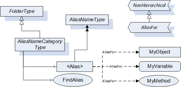
AliasNames is a concept in OPC UA (defined in OPC 10000-17) that allows defining alternate names for Objects, Variables or Methods in an AddressSpace (see Figure 15). These names can be grouped into categories. The FindAlias method returns the ExpandedNodeId for the actual Object/Variable/Method. AliasNames are most commonly used for configuration management, but can also be used for DataSet/topic discovery and many other uses.
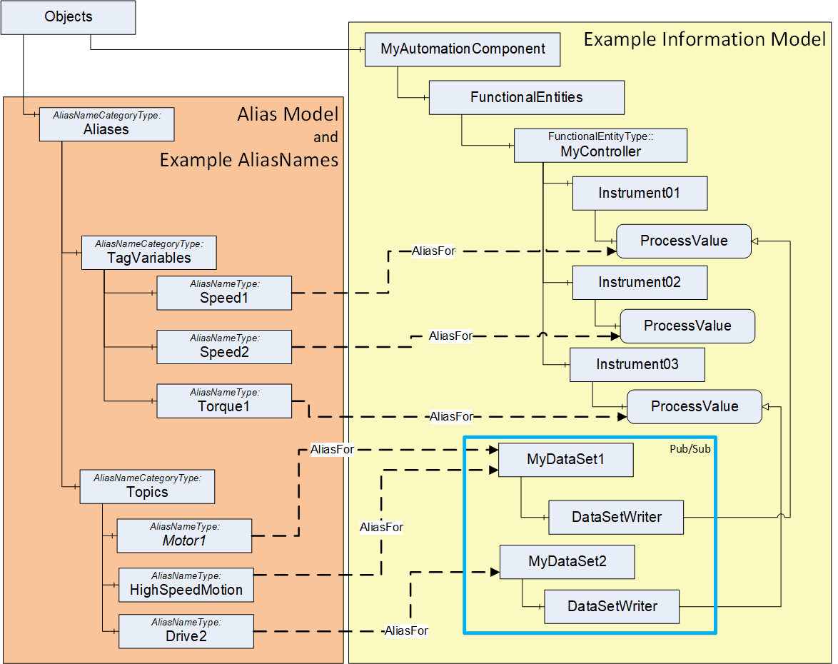
In OPC UA FX, AliasNames can be used to define a configuration for information used by the ConnectionManager. AliasNames allow offline engineering tools to assign alternate names to Variables or Objects that are used in the configuration (see Figure 16). These alternate names could be assigned and used long before the actual configuration is available. They can be exchanged between vendors, allowing vendors to configure Connections without having all the required data defined. The resolution of this configuration information into the actual Server / NodeId of the Node identified by the AliasName happens at runtime. The aggregation of AliasNames into a Global Discovery Server (GDS) happens automatically for Servers that are registered with a GDS. An AggregatingServer can also collect AliasNames.
5.8 Aggregation of OPC UA FX Servers
AggregatingServers can be used to collect information from multiple underlying Servers and add additional functionality to the information and/or source the information for higher-level applications, offloading the underlying Servers. The Information Model that is defined in this document can be aggregated. This clause provides some explanation regarding the aggregation of AutomationComponents and ConnectionManagers.
The AutomationComponent(s) can be reflected in a higher-level Server. This reflection can include Assets and FunctionalEntities, but it is expected that the communication model (between FunctionalEntities) will only exist in the actual Servers, not in the AggregatingServer. Any actions performed against the AutomationComponent in the AggregatingServer are expected to be passed down and performed on the actual Server, including any method calls. Also, only the status/configuration information from a ConnectionEndpoint would be mirrored. ControlGroup information can be displayed in an AggregatingServer. Still, all data just reflects data from the underlying Servers, so changes to values would only occur in the underlying Server and could only be made if no locks are in place. Any writes or Method calls made against an AutomationComponent on an AggregatingServer would need to be applied against the AutomationComponent in the underlying Server. The value in the AggregatingServer would only be updated due to mirroring the change in the underlying Server. The value would not be directly updated in the AggregatingServer.
An AggregatingServer can add functionality, such as the generation of Alarms or historization. It can also be the source of data for higher-level applications such as HMIs or advanced control applications. Multiple AutomationComponents from multiple Servers could be included under a single AggregatingServer.
An AggregatingServer can expose a ConnectionManager, but only one well-known ConnectionManager is allowed on a Server. This single ConnectionManager can reflect the ConnectionConfigurationSets from the underlying Servers. It can directly execute any commands it receives or pass the commands down to the underlying Servers.
5.9 Well Known Roles
All Servers supporting OPC UA FX should support the well-known Roles as defined in OPC 10000-3. The well-known Role ConfigureAdmin should be extended as indicated in Table 2.
| BrowseName | Suggested Permissions |
|---|---|
| 0:ConfigureAdmin | The Role is allowed to browse the Information Model, execute methods related to application configuration, and read and write non-security-related configuration settings. This includes changing connection and network-related configuration settings. Safety configuration is explicitly separate from this Role. |
All Servers supporting OPC UA FX should support the additional well-known Role as defined in Table 3.
| BrowseName | Suggested Permissions |
|---|---|
| 3:ConnectionAdmin | The Role is allowed to establish, close, and modify Connections between FunctionalEntities. This includes reading and writing connection configuration settings, reading endpoint and connection capabilities, and executing methods related to the management of Connections. It is intended to be a non-human Role. |
For a detailed description of Roles, see OPC 10000-3, OPC 10000-14, and OPC 10000-18.