5 Overview
5.1 Motivation
Today’s automation devices use a wide variety of different fieldbus systems and real-time Ethernet protocols to communicate on the control and field level. Although most of these fieldbus systems and real-time Ethernet protocols are standardised by IEC (61158/61784 series), many devices are not interoperable with each other. Many of these protocols support different network infrastructures. However, even if they support the same infrastructure, they cannot coexist in the same network. Also, device information is structured using different syntax and semantics, making data analysis a labour-intensive and time-consuming task vulnerable to error, especially in multi-vendor and multi-protocol environments.
The trend towards Industry 4.0 and IIoT requires concepts for vendor-independent end-to-end interoperability from sensor to cloud, including field-level devices for all relevant industrial automation use cases, including real-time, motion, security, and safety. A standardised communication protocol from sensor to cloud supports the digital transformation across all industries, including process control and discrete manufacturing. End-users and system integrators benefit from easier Controller integration and cross-vendor Controller-to-Controller interoperability. Seamless access to production data and process conditions facilitates less downtime and optimisation of production processes.
This approach requires standardisation on different levels, including semantics and information modelling, application profiles, communication protocols, and data link/physical level connections. An important aspect is the convergence of information technology (IT) and operational technology (OT), allowing a common network infrastructure to be shared by IT and OT traffic while guaranteeing different levels of Quality of Service demanded by diverse IT and OT applications.
5.2 The UAFX Solution
OPC UA FX specifies a standardised Information Model and connection model for AutomationComponents, providing timely data delivery, security, and functional safety. Interactions addressed by UAFX include Controller-to-Controller, Controller-to-Device, Controller-to-Compute, Device-to-Device, and Device-to-Compute. This release of the specification includes Controller-to-Controller interactions. Other interactions will be included in future releases.
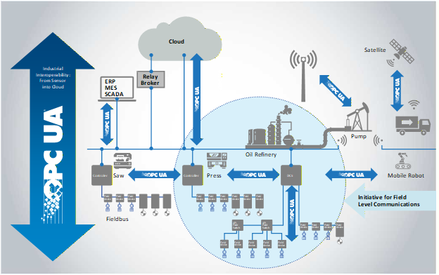
Figure 2 shows the scope of UAFX relative to the overall OPC UA integration patterns. UAFX extends the existing OPC UA communication solution (e.g., OPC 10000-14 and OPC 10000-100) to address industrial automation requirements in the discrete manufacturing and process industries, providing vendor-independent end-to-end interoperability of field-level devices for all relevant industrial automation use cases.
5.3 Interaction Model
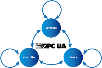
In the interaction model shown in Figure 3, a Controller represents a control automation component typically implemented in a PLC or DCS controller. Today, Devices may be connected to Controllers and can be as simple as an inductive proximity switch or as complex as a Coriolis flowmeter or servo drive. In the future, Devices may communicate directly with Compute application, eliminating the overhead of a Controller acting as an intermediary. Compute’s hardware aspect scales from a single-board computer-based data gateway to a blade server in the cloud. Examples of Compute applications include historians, analytics, and complete MESs.
These interactions can be depicted by dividing the participants into different categories: Controller-to-Controller, Controller-to-Device, Controller-to-Compute, Device-to-Device, and Device-to-Compute. The interactions within these categories are similar in many ways, but each category will include interactions unique to its use cases. Controllers and devices may have vastly different functions and roles; however, their functionality is modelled at an abstract level in UAFX as an AutomationComponent (see 6.2). While capabilities specific to Compute-to-Compute are not part of UAFX, these interactions will inherit and benefit from the increased harmonisation delivered at the field level.
5.4 Engineering workflow
5.4.1 General
UAFX defines a mechanism for standardising the exchange of information used for establishing Connections between AutomationComponents (see 6.2) in an OfflineEngineering environment (see 6.4). From initial AutomationComponent development to on-site commissioning, engineers exchange offline data using the Descriptor (see 6.4). See OPC 10000-83 for more details regarding OfflineEngineering and Descriptors.
Assets and FunctionalEntities being used in applications, their available input, output, and configuration data, and communication capabilities are shared between engineers using Descriptors. The Descriptor allows product and system configuration data to be added by different engineers using their engineering tools at each phase of the workflow until the configuration ultimately can be deployed in the field.
5.4.2 Actors
5.4.2.1 Overview
This subclause defines actors interacting with a UAFX system during the system’s engineering, which are referenced for workflow phase descriptions in all parts of the UAFX specifications.
5.4.2.2 Controls Engineer
Controls Engineers are responsible for the design of an automation or control system. Their primary responsibility is the programming/configuration of the application code in a PLC, PAC or DCS (etc.), which is necessary to execute algorithms that define the operation of a piece of equipment. In support of this function, they are typically responsible for integrating automation devices into the controller engineering tools and parameterising those devices with all information necessary for their correct functional operation.
There are multiple disciplines within the Controls Engineer category, including safety engineer, PLC programmer and process automation engineer, all of whom fulfil essentially the same function but with differing expertise.
5.4.2.3 Network Engineer
The Network Engineer, a peer to the Controls Engineer, is responsible for designing and configuring the network infrastructure and implementing network technologies. At the machine or skid level, the Network Engineer is often the same individual as the Controls Engineer.
5.4.2.4 Security Administrator
The Security Administrator has no direct stake in production operations or technologies. They are responsible for ensuring that there is no unauthorised access to production operations (whether from an outside hacker, inside bad actor or former employee). They are also charged with ensuring that the propagation of viruses, worms, malware, ransomware, etc., is restricted and that reasonable measures are taken to ensure resilience against these threats. They are responsible for the security of proprietary data entering and leaving facilities.
5.4.2.5 System Commissioner
The System Commissioner or commissioning engineer is responsible for the start-up of a system once it has been installed in a manufacturing/processing plant. In some cases, the System Commissioner may have operated as Controls Engineer earlier in the project lifecycle. For machine/skid builders, the commissioning engineer may never have met the Controls Engineer in person as they may work in different locations, or the machine design may be many years old.
5.4.3 Application engineering
Figure 4 shows an example of an engineering workflow where Controls Engineers A and B jointly create a control application consisting of Controller A and Controller B while separated in time and space and potentially without the physical devices. Using Controller A’s engineering tool, Engineer A creates the User Program for Controller A and describes the inputs and outputs to be shared. Engineer A then exports an updated, signed Descriptor with the shared information. Engineer B then imports this Descriptor using Controller B’s engineering tool and adds the information needed for Controller A and B Connections. Engineer B may import additional Descriptors describing components used with their Controller or other Controllers to be connected. Engineer B then adds the Connection configuration needed to exchange the data required for the application.
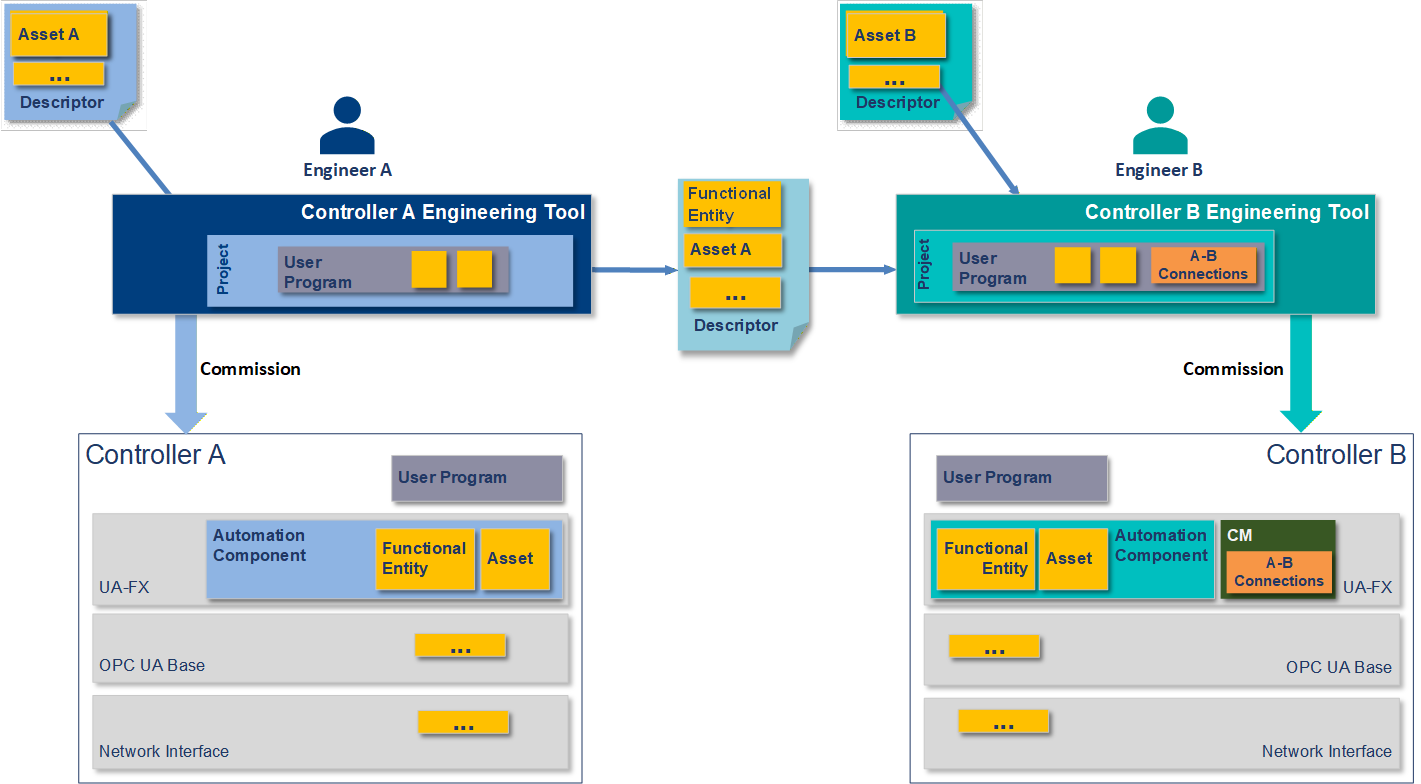
Engineer A and Engineer B deploy their applications to their respective Controllers and deliver them to the site. Initial network address assignment is a precondition for the following steps.
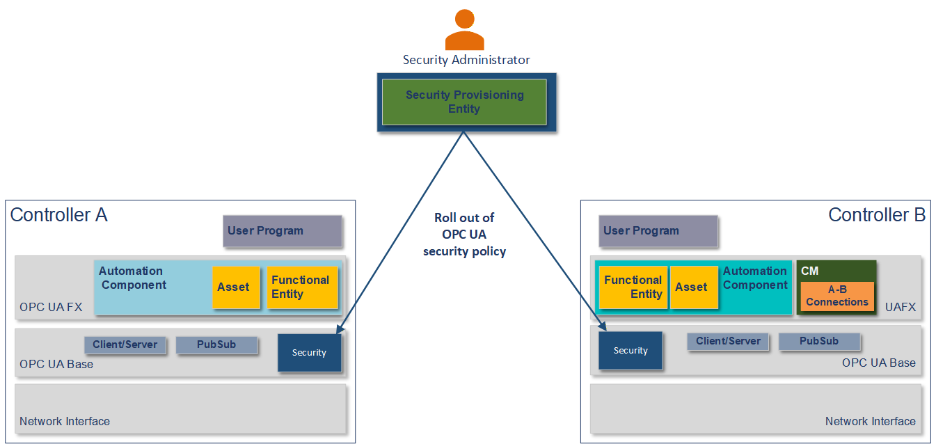
5.4.4 Security configuration
Using a Security Provisioning Entity, the Security Administrator configures the Controllers for OPC UA security and rolls out the security policy required for the site per Controller, as shown in Figure 5. The security policy contains, amongst others, certificates, roles, and user management. For PubSub, this includes the configuration of the SecurityKeyServer (see OPC 10000-14). The Security Administrator might use a GlobalDiscoveryServer (see OPC 10000-12) for security configuration.
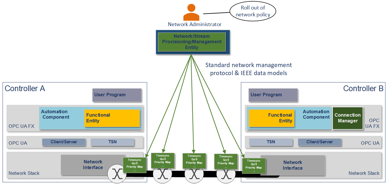
5.4.5 Network configuration
The Network Engineer commissions the Controllers with a hostname, DNS information, and an IP address or address acquisition mechanism such as DHCP. The Network Engineer may apply firmware or software updates if needed.
The Network Engineer then rolls out the network configuration as required for the site using vendor-independent mechanisms and tools, such as a Network Provisioning Entity, as shown in Figure 6. The network configuration contains, amongst others, VLAN usage, the configuration of time synchronisation, and the configuration of QoS (see 6.3).
5.4.6 System integration
The System Commissioner may adjust the Connection configuration, such as addresses of Connection partners, publishing intervals, and QoS mapping tables using a generic OPC UA client or a tool based on standard OPC UA Client Server services, as shown in Figure 7.
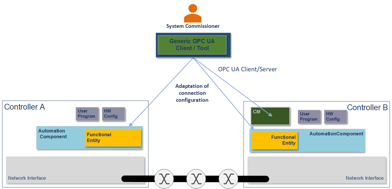
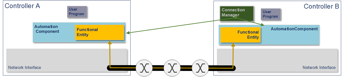
The ConnectionManager uses OPC UA Methods exposed by each AutomationComponent to establish the configured Connections when the system goes operational, as shown in Figure 8. See clause 6.2 for more details on Connections and the ConnectionManager.
See OPC 10000-81 for more details.