
7 OPC UA ObjectTypes
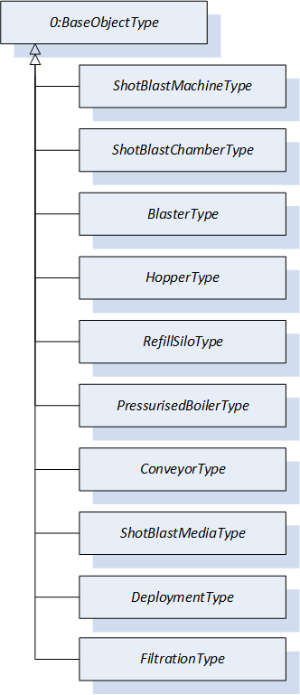
Figure 7 shows all ObjectTypes which are defined by this companion specification.
7.1 ShotBlastMachineType ObjectType Definition
The ShotBlastMachineType defines the representation of a shot blasting machine. This Object is the entry point into the OPC UA information model. The ShotBlastMachineType is defined in Table 15.
| Attribute | Value | ||||
| BrowseName | ShotBlastMachineType | ||||
| IsAbstract | False | ||||
| References | Node Class | BrowseName | DataType | TypeDefinition | Other |
|---|---|---|---|---|---|
| Subtype of the BaseObjectType defined in OPC 10000-5 | |||||
| 0:HasAddIn | Object | 2:Identification | 3:MachineIdentificationType | M | |
| 0:HasAddIn | Object | 3:Components | 3:MachineComponentsType | M | |
| 0:HasComponent | Object | ShotBlastMedia | ShotBlastMediaType | O | |
| 0:HasComponent | Object | Monitoring | 0:FolderType | O | |
| 0:HasComponent | Object | 3:MachineryBuildingBlocks | 0:FolderType | M | |
| Conformance Units | |||||
|---|---|---|---|---|---|
| ShotBlastMachine Basic | |||||
| ShotBlastMachine Media | |||||
| ShotBlastMachine Deployment Monitoring | |||||
| ShotBlastMachine RefillSilo | |||||
| ShotBlastMachine Pressurised | |||||
| ShotBlastMachine Filtration System | |||||
| ShotBlastMachine PAEFS Filtration System | |||||
| ShotBlastMachine StateMachines | |||||
| ShotBlastMachine JobManagement |
Identification is used as defined in OPC 40001-1 and shall also be referenced as AddIn in the MachineryBuildingBlocks Folder.
Components is representing a collection of all physical components of the shot blast machine.
ShotBlastingMedia is representing the material accelerated by the blaster for surface treatment of the workpiece.
Monitoring is representing a collection of the variables that are assigned to this specific component. All media and energy consumption should be mapped according to the DeploymentType and placed within the Monitoring folder. Furthermore, any Variables that are recorded over the entire machine should be placed within the Monitoring folder.
MachineryBuildingBlocks is representing a folder that directly references all those building blocks of the OPC UA for Machinery (OPC 40001-1, OPC 40001-3) which are implemented as an add-in in this specific component.
The components of the ShotBlastMachineType have additional references which are defined in Table 16.
| SourceBrowsePath | Reference Type | Is Forward | TargetBrowsePath |
| 3:MachineryBuildingBlocks | 0:HasAddIn | True | 2:Identification |
| 3:MachineryBuildingBlocks | 0:HasAddIn | True | 3:Components |
The components of the ShotBlastMachineType have additional subcomponents which are defined in Table 17.
| Source Path | Reference | NodeClass | BrowseName | DataType | TypeDefinition | Others |
| 3:Components | 0:HasComponent | Object | <ShotBlastChamber> | ShotBlastChamberType | MP | |
| 3:Components | 0:HasComponent | Object | <Hopper> | HopperType | MP | |
| 3:Components | 0:HasComponent | Object | <RefillSilo> | RefillSiloType | OP | |
| 3:Components | 0:HasComponent | Object | <PressurisedBoiler> | PressurisedBoilerType | OP | |
| 3:Components | 0:HasComponent | Object | <Conveyor> | ConveyorType | OP | |
| 3:Components | 0:HasComponent | Object | <FiltrationSystem> | FiltrationType | OP | |
| Monitoring | 0:HasComponent | Object | <ShotBlastMediaSupply> | DeploymentType | OP | |
| Monitoring | 0:HasComponent | Object | <Water> | DeploymentType | OP | |
| Monitoring | 0:HasComponent | Object | <Electricity> | DeploymentType | OP | |
| Monitoring | 0:HasComponent | Object | <PressurisedAir> | DeploymentType | OP | |
| 3:MachineryBuildingBlocks | 0:HasAddIn | Object | 3:OperationCounter | 3:MachineryOperationCounterType | O | |
| 3:MachineryBuildingBlocks | 0:HasAddIn | Object | 3:LifetimeCounter | 3:MachineryLifetimeCounterType | O | |
| 3:MachineryBuildingBlocks | 0:HasAddIn | Object | 3:MachineryOperationMode | 3:MachineryOperationModeStateMachineType | O | |
| 3:MachineryBuildingBlocks | 0:HasAddIn | Object | 3:MachineryItemState | 3:MachineryItemState_StateMachineType | O | |
| 3:MachineryBuildingBlocks | 0:HasAddIn | Object | 5:JobManagement | 5:JobManagementType | O |
Note: All media and energy consumption should be mapped according to the DeploymentType and placed within the Monitoring folder. Furthermore, any variables that are recorded over the entire machine should be placed within the Monitoring folder.
ShotBlastChamber is representing the enclosed working area in which the blasting media is projected onto the workpiece.
Hopper is representing the main working storage for the shotblast media.
RefillSilo is representing the refill working storage with new shotblast media.
PressurisedBoiler is representing the main working storage for air blast machines.
Conveyor is representing the system that transports the workpiece within the shot blasting area.
FiltrationSystem is representing the system that is responsible for handling the existing process air and its filter unit.
ShotBlastMediaSupply is representing the consumption of blasting material during the blasting process.
Water is representing the consumption of water of the shot blast machine.
Electricity is representing the consumption of electricity of the shot blast machine.
PressurisedAir is representing the consumption of pressurized air of the shot blast machine.
OperationCounter is used as defined in OPC 40001-1. In the information model for shot blasting machines, all counters that are implemented according to the MachineryOperationCounterType of the OPC 40001-1 shall be integrated with the HasComponent reference under this Object. This Object shall also be referenced as AddIn in the MachineryBuildingBlocks Folder.
LifetimeCounter is used as defined in OPC 40001-1. In the information model for shot blasting machines, all counters that are implemented according to the MachineryLifetimeCounterType of the OPC 40001-1 shall be integrated with the HasComponent reference under this Object. This Object shall also be referenced as AddIn in the MachineryBuildingBlocks Folder.
OperationMode is to be used as decribed by OPC 40001-1 and shall also be referenced as AddIn in the MachineryBuildingBlocks Folder.
MachineryItemState is to be used as decribed by OPC 40001-1 and shall also be referenced as AddIn in the MachineryBuildingBlocks Folder.
JobManagement is used as defined in OPC 40001-3 and shall also be referenced as AddIn in the MachineryBuildingBlocks Folder.
7.2 ShotBlastChamberType ObjectType Definition
The ShotBlastChamberType is representing the TypeDefinition of the enclosed shot blasting chamber in which the blasting media is projected onto the workpiece. A shot blasting machine has at least one shot blast chamber, but can also be configured with several shot blasting chambers.
The ShotBlastChamberType is formally defined in Table 18.
| Attribute | Value | ||||
| BrowseName | ShotBlastChamberType | ||||
| IsAbstract | False | ||||
| References | Node Class | BrowseName | DataType | TypeDefinition | Other |
|---|---|---|---|---|---|
| Subtype of the BaseObjectType defined in OPC 10000-5 | |||||
| 0:HasAddIn | Object | 2:Identification | 3:MachineIdentificationType | M | |
| 0:HasAddIn | Object | 3:Components | 3:MachineComponentsType | M | |
| 0:HasProperty | Variable | LoadingState | 0:Boolean | 0:PropertyType | M |
| 0:HasComponent | Object | 3:MachineryBuildingBlocks | 0:FolderType | M | |
| Conformance Units | |||||
|---|---|---|---|---|---|
| ShotBlastChamber Multiple Blasters |
Identification is used as defined in OPC 40001-1 and shall also be referenced as AddIn in the MachineryBuildingBlocks Folder.
Components is representing a collection of all physical components of the shot blasting machine.
Blaster is representing the device which accelerates the shot blasting media either a rotating wheel with blades or by pressurized air.
LoadingState is indicating the status whether the shot blast machine is loaded with a workpiece or not. True means the shotblast chamber is loaded.
MachineryBuildingBlocks is representing a folder that directly references all those building blocks of the OPC UA for Machinery (OPC 40001-1, OPC 40001-3) which are implemented as an add-in in this specific component.
The components of the ShotBlastChamberType have additional references which are defined in Table 19.
| SourceBrowsePath | Reference Type | Is Forward | TargetBrowsePath |
| 3:MachineryBuildingBlocks | 0:HasAddIn | True | 2:Identification |
| 3:MachineryBuildingBlocks | 0:HasAddIn | True | 3:Components |
The components of the ShotBlastChamberType have additional subcomponents which are defined in Table 23.
| Source Path | Reference | NodeClass | BrowseName | DataType | TypeDefinition | Others |
| 3:Components | 0:HasComponent | Object | <Blaster> | BlasterType | MP |
Blaster is representing the device which accelerates the shot blasting media either a rotating wheel with blades or by pressurized air.
7.3 BlasterType ObjectType Definition
The BlasterType is representing the TypeDefinition of the blaster which accelerates the shot blasting media either a rotating wheel with blades or by pressurized air. A blaster is a mandatory component of a shot blasting chamber. A shot blasting chamber can be configured with one or more blasters.
The BlasterType is formally defined in Table 21.
| Attribute | Value | ||||
| BrowseName | BlasterType | ||||
| IsAbstract | False | ||||
| References | Node Class | BrowseName | DataType | TypeDefinition | Other |
|---|---|---|---|---|---|
| Subtype of the BaseObjectType defined in OPC 10000-5 | |||||
| 0:HasAddIn | Object | 2:Identification | 3:MachineryComponentIdentificationType | M | |
| 0:HasComponent | Object | Monitoring | 0:FolderType | M | |
| 0:HasComponent | Object | 3:MachineryBuildingBlocks | 0:FolderType | M | |
| Conformance Units | |||||
|---|---|---|---|---|---|
| Wheel Blaster | |||||
| Pressurised Blaster |
Identification is used as defined in OPC 40001-1 and shall also be referenced as AddIn in the MachineryBuildingBlocks Folder.
Monitoring is representing a collection of the variables that are assigned to this specific component.
MachineryBuildingBlocks is representing a folder that directly references all those building blocks of the OPC UA for Machinery (OPC 40001-1, OPC 40001-3) which are implemented as an add-in in this specific component.
The components of the BlasterType have additional references which are defined in Table 22.
| SourceBrowsePath | Reference Type | Is Forward | TargetBrowsePath |
| 3:MachineryBuildingBlocks | 0:HasAddIn | True | 2:Identification |
The components of the BlasterType have additional subcomponents which are defined in Table 23.
| Source Path | Reference | NodeClass | BrowseName | DataType | TypeDefinition | Others |
| Monitoring | 0:HasComponent | Variable | ShotBlastMediaThroughput | 0:Double | 0:AnalogUnitType | O |
| Monitoring | 0:HasComponent | Variable | ShotBlastMediaThroughputPercent | 0:UInt16 | 0:AnalogUnitType | O |
| Monitoring | 0:HasProperty | Variable | ShotBlastTime | 0:Duration | 0:PropertyType | O |
| Monitoring | 0:HasComponent | Variable | ShotBlastPressure | 0:Double | 0:AnalogUnitType | O |
| Monitoring | 0:HasComponent | Variable | WheelRotationSpeed | 0:Int32 | 0:AnalogUnitType | O |
ShotBlastMediaThroughput is representing the shot blast media throughput per shot blaster.
ShotBlastMediaThroughputPercent is representing the shot blasting media throughput per shot blaster in percent of the maximum throughput capacity.
ShotBlastTime is representing the duration in which the blaster processes shot blasting media.
ShotBlastPressure is representing the air pressure in the pressurized boiler.
WheelRotationSpeed is representing the rotational speed of the shot blast wheel.
7.4 HopperType ObjectType Definition
The HopperType is representing the TypeDefinition of the main working storage for the shotblast media.
The HopperType is formally defined in Table 24.
| Attribute | Value | ||||
| BrowseName | HopperType | ||||
| IsAbstract | False | ||||
| References | Node Class | BrowseName | DataType | TypeDefinition | Other |
|---|---|---|---|---|---|
| Subtype of the BaseObjectType defined in OPC 10000-5 | |||||
| 0:HasComponent | Object | Monitoring | 0:FolderType | O | |
| Conformance Units | |||||
|---|---|---|---|---|---|
| Hopper Fill Level Monitoring |
Monitoring is representing a collection of the variables that are assigned to this specific component.
The components of the HopperType have additional subcomponents which are defined in Table 25.
| Source Path | Reference | NodeClass | BrowseName | DataType | TypeDefinition | Others |
| Monitoring | 0:HasProperty | Variable | HopperLevelMax | 0:Boolean | 0:PropertyType | O |
| Monitoring | 0:HasProperty | Variable | HopperLevelMin | 0:Boolean | 0:PropertyType | O |
HopperLevelMax is indicating that the maximum fill level of the hopper has been reached. True means the maximum fill level has been reached.
HopperLevelMin is indicating that the minimum fill level of the hopper has been reached. True means the minimum fill level has been reached.
7.5 RefillSiloType ObjectType Definition
The RefillSiloType is representing the TypeDefinition of the refill working storage with new shotblast media.
The RefillSiloType is formally defined in Table 26.
| Attribute | Value | ||||
| BrowseName | RefillSiloType | ||||
| IsAbstract | False | ||||
| References | Node Class | BrowseName | DataType | TypeDefinition | Other |
|---|---|---|---|---|---|
| Subtype of the BaseObjectType defined in OPC 10000-5 | |||||
| 0:HasComponent | Object | Monitoring | 0:FolderType | O | |
Monitoring is representing a collection of the variables that are assigned to this specific component.
The components of the RefillSiloType have additional subcomponents which are defined in Table 27.
| Source Path | Reference | NodeClass | BrowseName | DataType | TypeDefinition | Others |
| Monitoring | 0:HasProperty | Variable | RefillSiloLevelMax | 0:Boolean | 0:PropertyType | O |
| Monitoring | 0:HasProperty | Variable | RefillSiloLevelMin | 0:Boolean | 0:PropertyType | O |
RefillSiloLevelMax is indicating that the maximum fill level of the refill silo has been reached. True means the maximum fill level has been reached.
RefillSiloLevelMin is indicating that the minimum fill level of the refill silo has been reached. True means the minimum fill level has been reached.
7.6 PressurisedBoilerType ObjectType Definition
The PressurisedBoilerType is representing the TypeDefinition of the main working storage for air blast machines.
The PressurisedBoilerType is formally defined in Table 28.
| Attribute | Value | ||||
| BrowseName | PressurisedBoilerType | ||||
| IsAbstract | False | ||||
| References | Node Class | BrowseName | DataType | TypeDefinition | Other |
|---|---|---|---|---|---|
| Subtype of the BaseObjectType defined in OPC 10000-5 | |||||
| 0:HasAddIn | Object | 2:Identification | 3:MachineryComponentIdentificationType | M | |
| 0:HasComponent | Object | Monitoring | 0:FolderType | M | |
| 0:HasComponent | Object | 3:MachineryBuildingBlocks | 0:FolderType | M | |
Identification is used as defined in OPC 40001-1 and shall also be referenced as AddIn in the MachineryBuildingBlocks Folder.
Monitoring is representing a collection of the variables that are assigned to this specific component.
MachineryBuildingBlocks is representing a folder that directly references all those building blocks of the OPC UA for Machinery (OPC 40001-1, OPC 40001-3) which are implemented as an add-in in this specific component.
The components of the PressurisedBoilerType have additional references which are defined in Table 29.
| SourceBrowsePath | Reference Type | Is Forward | TargetBrowsePath |
| 3:MachineryBuildingBlocks | 0:HasAddIn | True | 2:Identification |
The components of the PressurisedBoilerType have additional subcomponents which are defined in Table 30.
| Source Path | Reference | NodeClass | BrowseName | DataType | TypeDefinition | Others |
| Monitoring | 0:HasProperty | Variable | PressurisedBoilerLevelMax | 0:Boolean | 0:PropertyType | O |
| Monitoring | 0:HasProperty | Variable | PressurisedBoilerLevelMin | 0:Boolean | 0:PropertyType | O |
| Monitoring | 0:HasComponent | Variable | StoragePressure | 0:Double | 0:AnalogUnitType | O |
PressurisedBoilerLevelMax is indicating that the maximum fill level of the pressurized boier has been reached. True means the maximum fill level has been reached.
PressurisedBoilerLevelMin is indicating that the minimum fill level of the pressurized boiler has been reached. True means the minimum fill level has been reached.
StoragePressure is representing the current pressure inside of the pressurized boiler.
7.7 ConveyorType ObjectType Definition
The ConveyorType is representing the component that is used to transport the part to be processed.
The ConveyorType is formally defined in Table 31.
| Attribute | Value | ||||
| BrowseName | ConveyorType | ||||
| IsAbstract | False | ||||
| References | Node Class | BrowseName | DataType | TypeDefinition | Other |
|---|---|---|---|---|---|
| Subtype of the BaseObjectType defined in OPC 10000-5 | |||||
| 0:HasAddIn | Object | 2:Identification | 3:MachineryComponentIdentificationType | M | |
| 0:HasComponent | Object | Monitoring | 0:FolderType | O | |
| 0:HasComponent | Object | 3:MachineryBuildingBlocks | 0:FolderType | M | |
Identification is used as defined in OPC 40001-1 and shall also be referenced as AddIn in the MachineryBuildingBlocks Folder.
Monitoring is representing a collection of the variables that are assigned to this specific component.
MachineryBuildingBlocks is representing a folder that directly references all those building blocks of the OPC UA for Machinery (OPC 40001-1, OPC 40001-3) which are implemented as an add-in in this specific component.
The components of the ConveyorType have additional references which are defined in Table 32.
| SourceBrowsePath | Reference Type | Is Forward | TargetBrowsePath |
| 3:MachineryBuildingBlocks | 0:HasAddIn | True | 2:Identification |
The components of the ConveyorType have additional subcomponents which are defined in Table 33.
| Source Path | Reference | NodeClass | BrowseName | DataType | TypeDefinition | Others |
| Monitoring | 0:HasComponent | Variable | ConveyorTransportSpeed | 0:Double | 0:AnalogUnitType | O |
| Monitoring | 0:HasComponent | Variable | WorkpieceRotationSpeed | 0:Double | 0:AnalogUnitType | O |
ConveyorTransportSpeed is representing the current speed at which the workpiece is moved by the conveyor.
WorkpieceRotationSpeed is representing the current rotational speed at which the workpiece is rotated by the conveyor.
7.8 ShotBlastMediaType ObjectType Definition
The ShotBlastMediaType provides all necessary information on the blasting material used in the blasting process. It is formally defined in Table 34.
| Attribute | Value | ||||
| BrowseName | ShotBlastMediaType | ||||
| IsAbstract | False | ||||
| References | Node Class | BrowseName | DataType | TypeDefinition | Other |
|---|---|---|---|---|---|
| Subtype of the BaseObjectType defined in OPC 10000-5 | |||||
| 0:HasProperty | Variable | ShotBlastMediaName | 0:String | 0:PropertyType | O |
| 0:HasProperty | Variable | ShotBlastMediaManufacturer | 0:String | 0:PropertyType | O |
| 0:HasComponent | Variable | NominalParticleSizeAverage | 0:Double | 0:BaseDataVariableType | O |
| 0:HasComponent | Variable | NominalParticleSizeRange | 0:Range | 0:BaseDataVariableType | O |
| 0:HasComponent | Variable | ActualParticleSizeRange | 0:Range | 0:BaseDataVariableType | O |
| 0:HasComponent | Variable | ShotBlastMediaHardnessAverage | 0:Double | 0:BaseDataVariableType | O |
| 0:HasComponent | Variable | ShotBlastMediaHardnessRange | 0:Range | 0:BaseDataVariableType | O |
| 0:HasProperty | Variable | ShotBlastMediaBatch | 0:String | 0:PropertyType | O |
ShotBlastMediaName is representing the name of the current used shot blast material.
ShotBlastMediaManufacturer is representing the manufacturers name of the current used shot blast material.
NominalParticleSizeAverage is representing the average particle size of the current used shot blast material.
NominalParticleSizeRange is representing the particle size range of the current used shot blast material.
ActualParticleSizeRange is representing the actual measured particle size range of the current used shot blast material.
ShotBlastMediaHardnessAverage is representing the average hardness of the current used shot blast material.
ShotBlastMediaHardnessRange is representing hardness range of the current used shot blast.
ShotBlastMediaBatch is representing a string that is identifying the charge of the used shot blast material.
The components of the ShotBlastMediaType have additional subcomponents which are defined in Table 35.
| Source Path | Reference | NodeClass | BrowseName | DataType | TypeDefinition | Others |
| ShotBlastMediaHardnessAverage | 0:HasComponent | Variable | ShotBlastMediaHardnessUnit | 0:UInt16 | 0:MultiStateValueDiscreteType | M |
| ShotBlastMediaHardnessRange | 0:HasComponent | Variable | ShotBlastMediaHardnessUnit | 0:UInt16 | 0:MultiStateValueDiscreteType | M |
The component Variables of the ShotBlastMediaType have additional Attributes defined in Table 36.
| BrowsePath | Value Attribute | Description Attribute | |||
| [ {"Value": 0, “DisplayName": “HRC”, "Description": “”}, {“Value": 1, “DisplayName": “HV”, "Description": “”}, {“Value": 2, “DisplayName": “MOHS”, "Description": “”}, {“Value": 3, “DisplayName": “HB”, "Description": “”} ] | ||||
| [ {"Value": 0, “DisplayName": “HRC”, "Description": “”}, {“Value": 1, “DisplayName": “HV”, "Description": “”}, {“Value": 2, “DisplayName": “MOHS”, "Description": “”}, {“Value": 3, “DisplayName": “HB”, "Description": “”} ] |
7.9 DeploymentType ObjectType Definition
An object with the definition DeploymentType represents a media or energy deployment. Examples of this are water consumption, electricity consumption or the consumption of blasting material. The object is not limited to a list of media or energy sources and can map any deployment. It is formally defined in Table 37.
| Attribute | Value | ||||
| BrowseName | DeploymentType | ||||
| IsAbstract | False | ||||
| References | Node Class | BrowseName | DataType | TypeDefinition | Other |
|---|---|---|---|---|---|
| Subtype of the BaseObjectType defined in OPC 10000-5 | |||||
| 0:HasComponent | Variable | ConsumedMedia | 0:UInt16 | 0:MultiStateValueDiscreteType | M |
| 0:HasComponent | Variable | ActualConsumption | 0:Double | 0:AnalogUnitType | O |
| 0:HasComponent | Variable | TotalConsumption | 0:Double | 0:AnalogUnitType | O |
ConsumedMedia is representing the type of media consumption that is mapped by this object.
ActualConsumption is representing the current consumption of the consumed media.
TotalConsumption is representing the total consumption of the consumed media during a defined time.
The components of the DeploymentType have additional subcomponents which are defined in Table 38.
| Source Path | Reference | NodeClass | BrowseName | DataType | TypeDefinition | Others |
| TotalConsumption | 0:HasProperty | Variable | ConsumingPeriod | UtcTime | 0:PropertyType | O |
ConsumingPeriod is representing the time interval in which the TotalConsumption is recorded.
The component Variables of the DeploymentType have additional Attributes defined in Table 39.
| BrowsePath | Value Attribute | Description Attribute | ||
| [ {"Value": 0, “DisplayName": “Shotblast Media”, "Description": “”}, {“Value": 1, “DisplayName": “Electricity”, "Description": “”}, {“Value": 2, “DisplayName": “Water”, "Description": “”}, {“Value": 3, “DisplayName": “Pressurised Air”, "Description": “”} ] |
7.10 FiltrationType ObjectType Definition
The FiltrationType provides all necessary information needed for a simple filtration system of a shot blast machine. It is formally defined in Table 40.
| Attribute | Value | ||||
| BrowseName | FiltrationType | ||||
| IsAbstract | False | ||||
| References | Node Class | BrowseName | DataType | TypeDefinition | Other |
|---|---|---|---|---|---|
| Subtype of the BaseObjectType defined in OPC 10000-5 | |||||
| 0:HasAddIn | Object | 2:Identification | 3:MachineryComponentIdentificationType | M | |
| 0:HasComponent | Object | Monitoring | 0:FolderType | M | |
| 0:HasComponent | Object | 3:MachineryBuildingBlocks | 0:FolderType | M | |
| Conformance Units | |||||
|---|---|---|---|---|---|
| Filtration Status Monitoring |
Identification is used as defined in OPC 40001-1 and shall also be referenced as AddIn in the MachineryBuildingBlocks Folder.
Monitoring is representing a collection of the variables that are assigned to this specific component.
MachineryBuildingBlocks is representing a folder that directly references all those building blocks of the OPC UA for Machinery (OPC 40001-1, OPC 40001-3) which are implemented as an add-in in this specific component.
The components of the FiltrationType have additional references which are defined in Table 41.
| SourceBrowsePath | Reference Type | Is Forward | TargetBrowsePath |
| 3:MachineryBuildingBlocks | 0:HasAddIn | True | 2:Identification |
The components of the FiltrationType have additional subcomponents which are defined in Table 42.
| Source Path | Reference | NodeClass | BrowseName | DataType | TypeDefinition | Others |
| Monitoring | 0:HasProperty | Variable | FilterRunning | 0:Boolean | 0:PropertyType | M |
| Monitoring | 0:HasProperty | Variable | FlowRateOK | 0:Boolean | 0:PropertyType | O |
| Monitoring | 0:HasProperty | Variable | FilterCleaningRunning | 0:Boolean | 0:PropertyType | O |
| Monitoring | 0:HasProperty | Variable | DifferentialPressureMax | 0:Boolean | 0:PropertyType | O |
| Monitoring | 0:HasProperty | Variable | DifferentialPressureMin | 0:Boolean | 0:PropertyType | O |
| Monitoring | 0:HasProperty | Variable | DischargeSystemRunning | 0:Boolean | 0:PropertyType | O |
| Monitoring | 0:HasProperty | Variable | ResidualDustOK | 0:Boolean | 0:PropertyType | O |
| Monitoring | 0:HasComponent | Variable | DifferentialPressure | 0:Double | 0:AnalogUnitType | O |
| Monitoring | 0:HasComponent | Variable | TemperatureFilterUnit | 0:Double | 0:AnalogUnitType | O |
| Monitoring | 0:HasComponent | Variable | FillLevel<n> | 0:UInt16 | 0:AnalogUnitType | OP |
| Monitoring | 0:HasComponent | Variable | FlowRate | 0:Double | 0:AnalogUnitType | O |
| Monitoring | 0:HasComponent | Variable | ResidualDust | 0:Double | 0:AnalogUnitType | O |
| 3:MachineryBuildingBlocks | 0:HasAddIn | Object | 3:MachineryItemState | 3:MachineryItemState_StateMachineType | O |
FilterRunning is representing the state of the fan of the filtration system. True means the fan is running.
FlowRateOK is indicating that the air flow inside of the piping system is okay.
FilterCleaningRunning is representing the state of the cleaning system of the filter unit. True means the cleaning system is currently cleaning the filter unit.
DifferentialPressureMax is indicating if the maximum differential pressure is reached.
DifferentialPressureMin is indicating if the minimum differential pressure is reached.
DischargeSystemRunning is representing the state of the device used to remove collected filter material from the filter unit.
ResidualDustOK is indicating if the exhaust gas is properly cleaned and inside the needed tolerances.
DifferentialPressure is representing the current pressure difference between the two sides of the filter unit.
TemperatureFilterUnit is representing the current temperature of the filter unit.
FillLevel<n> indicates the fill level of a device. As this Variable is an optional placeholder it can be instantiated as often as needed.
FlowRate is representing the air flow inside of the piping system.
ResidualDust is representing the quality of the exhaust gas exiting the filtration system.