
4 General Information on Weighing Technology and OPC UA
4.1 Introduction to Weighing Technology Companion Specification
Scales are used in a wide range of applications. Therefore, this section describes the schematic structure of a scale and includes a simple classification of scale types.
4.1.1 Schematic Structure of a Scale system
In addition to the definition of a scale of OIML R76 the following definition applies:
A scale is a computer system, device or measuring instrument used to determine the mass or mass flow of a quantity of material and consisting of one or more weighing modules (including load receptor, load-transmitting device, load cell and data processing device) and additional modules or peripheral devices (see Figure 1). Each weighing module determines a mass. The weighing result of the scale may be the result of one weighing module or the addition of several weighing modules. Not all partial results need to be included in the result.
In addition, a scale can also have subdevices such as printers or feeder systems. Each scale needs a data processing device and at least one interface like a display or field bus. Thus, an interaction other than OPC UA is always possible.
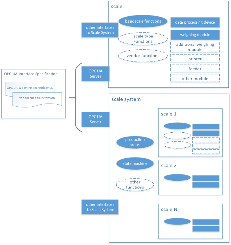
Each scale provides a specific set of functions. These functions can be divided into three categories. The basic set of functions is available for all scales and behaves the same way for all scales. The scale type functions depend on the scale types (see Section 5.1.2) and behave the same within this type. An example is the administration of zones at the checkweigher or the administration of recipes at the recipe scale. In addition, further functions or applications can be specifically defined by a vendor.
A scale system is the combination of several scales that are addressed by a common interface and can have additional functions, such as a state machine or a production preset. However, a scale must be included in any case.
The schematic described here is a significant simplification of scales and focuses on the external representation of entire scale systems. It does not include any metrological details. In addition, real systems can deviate significantly from this schematic.
4.1.2 Introduction into scale classification
This classification of the scales is based on the aspect of communication via OPC UA. If possible, existing classifications (e.g., from OIML) were used. However, further conflicting classifications may exist. Since the boundaries are partly fluid, some devices can be assigned to several scale types. The resulting classification is shown in Figure 2.
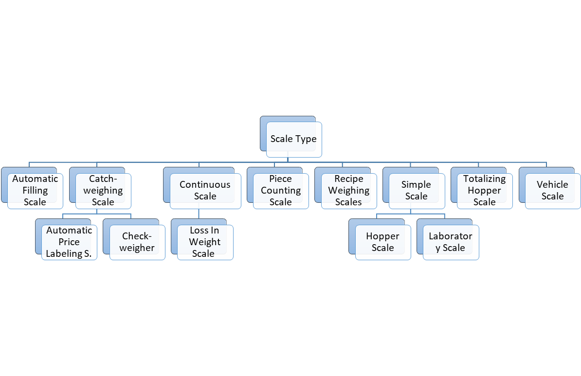
The definitions of the individual types can be found in Table 9.
| Term | Definition |
| Automatic Filling Scale | Instrument which fills containers with predetermined and virtually constant mass of product from bulk by automatic weighing, and which comprises essentially automatic feeding device(s) associated with weighing unit(s) and the appropriate control and discharge devices. (Definition is based on OIML R61) |
| Catchweighing Scale (catchweigher) | Automatic weighing instrument that weighs pre-assembled discrete loads or single loads of loose material. (Definition is based on OIML R51) |
| Automatic Weight Labeling Scale | catchweigher that labels individual pre-assembled discrete loads (e.g., prepackages) with the weight value. (Definition is based on OIML R51) |
| Automatic Price Labeling Scale | catchweigher that calculates the price to pay on the basis of the indicated mass and the unit price and labels individual pre-assembled discrete loads (e.g., prepackages with the weight value, unit price and price to pay). (Definition is based on OIML R51) |
| checkweigher | catchweigher that sub-divides prepackages of different mass into two or more sub-groups according to the value of the difference between their mass and the nominal set point. (Definition is based on OIML R51) |
| Continuous Scale | An automatic weighing instrument for continuously weighing a bulk product on a conveyor belt (or other mechanical facilities), without systematic subdivision of the mass and without interrupting the movement of the conveyor belt. (Definition is based on OIML R50) |
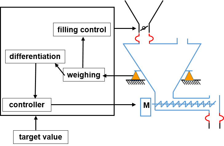
| Loss In Weight Scale | A special type of continuous scale is the loss in weight scale. It works according to the principle of controlled material increase or removal. The weight of the material is weighed by load cells and the change in weight per time unit is determined. The change in weight corresponds to the actual feed rate of the feeder when re-filling or emptying is stopped. A schematic overview is shown in Figure 3. |
| Piece Counting Scale | A scale that can determine the number of parts in the load. A reference weight must first be determined or stored. |
| Recipe Weighing Scale | Scale with the capacity to manage and process recipes. Single recipe steps in a recipe can be the weighing of ingredients, the display of user instructions, the monitoring of switching values or the activation of aggregates. |
| Simple Scale | Simple scales do not have any major functional extensions and provide only basic weighing functionality, i.e., acting as a sensor. |
| Hopper Scale | A scale for weighing a bulk product with a tank, vessel, box or hopper mounted on one or more weighing bridges. The primary use case is tank level monitoring. |
| Laboratory Scale | The laboratory scales have a particularly high resolution and represent highly sensitive measuring instruments. For this reason, additional processes and measures are necessary to carry out an accurate measurement. For this purpose, e.g., the shielding of the environment with additional signs may be necessary. |
Totalizing Hopper Scale | An automatic weighing instrument that weighs a bulk product by dividing it into discrete loads, determining the mass of each discrete load in sequence, summing the weighing results and delivering the discrete loads to bulk. (Definition is based on OIML R107) |
| Vehicle Scale | Automatic or non-automatic scale having one or more weight bridges that determines the mass of a vehicle. The load is typically a truck with or without a trailer or a rail wagon. A special variant is the automatic rail-weighbridge (see OIML R106), which has one or more load receptors, including rails for the transport of rail vehicles, which determine the mass of the wagons and/or of the entire train by weighing during travel. |
4.1.3 Product Handle Handling of product-related information
In addition to measuring, scales may also perform other tasks such as managing product data (production presetting and statistics/production output). To ensure that product-related information does not become inconsistent during the weighing process, it must be protected accordingly. For this purpose, a corresponding product information handle model shown in Figure 4 is described in this Companion Specification. It defines two different modes (ProductHandleMode/AccessRestrictionMode).
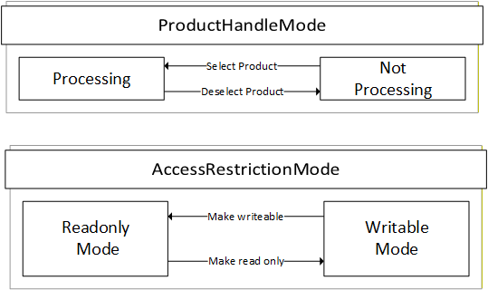
The ProductHandleMode indicates if a product can currently be processed by the scale or not. It is possible that the product-related information can be writeable or read only in both modes. The transition between the two states of the mode can be triggered internally in the scale or via the OPC UA methods SelectProduct, DeselectProduct, SwitchProduct (see sections 7.7 - 7.8). In some cases, it is possible that several products are in the "Processing" mode. For example, a catchweigher can process different products in parallel, while a continuous scale can only process one product at a time.
The AccessRestrictionMode can be used to define the access restriction of the product. A client can make a set of changes (e.g., multiple write operations and method calls) only when the mode is in "WritableMode". This mode applies to the entire product Object, including all components such as zones. The access level of all child nodes of the product Object should at least have written access and the method should be executable. The AccessRestritionMode is used via the LockingService descripted in OPC 10000-100.
4.2 Introduction to OPC Unified Architecture
4.2.1 What is OPC UA?
OPC UA is an open and royalty free set of standards designed as a universal communication protocol. While there are numerous communication solutions available, OPC UA has key advantages:
A state of art security model (see OPC 10000-2).
A fault tolerant communication protocol.
An information modelling framework that allows application developers to represent their data in a way that makes sense to them.
OPC UA has a broad scope which delivers for economies of scale for application developers. This means that a larger number of high-quality applications at a reasonable cost are available. When combined with semantic models such as Weighing Technology Companion Specification, OPC UA makes it easier for end users to access data via generic commercial applications.
The OPC UA model is scalable from small devices to ERP systems. OPC UA Servers process information locally and then provide that data in a consistent format to any application requesting data - ERP, MES, PMS, Maintenance Systems, HMI, Smartphone or a standard Browser, for examples. For a more complete overview see OPC 10000-1.
4.2.2 Basics of OPC UA
As an open standard, OPC UA is based on standard internet technologies, like TCP/IP, HTTP, Web Sockets.
As an extensible standard, OPC UA provides a set of Services (see OPC 10000-4) and a basic information model framework. This framework provides an easy manner for creating and exposing vendor defined information in a standard way. More importantly all OPC UA Clients are expected to be able to discover and use vendor-defined information. This means OPC UA users can benefit from the economies of scale that come with generic visualization and historian applications. This specification is an example of an OPC UA Information Model designed to meet the needs of developers and users.
OPC UA Clients can be any consumer of data from another device on the network to browser based thin clients and ERP systems. The full scope of OPC UA applications is shown in Figure 5.

OPC UA provides a robust and reliable communication infrastructure having mechanisms for handling lost messages, failover, heartbeat, etc. With its binary encoded data, it offers a high-performing data exchange solution. Security is built into OPC UA as security requirements become more and more important especially since environments are connected to the office network or the internet and attackers are starting to focus on automation systems.
4.2.3 Information modelling in OPC UA
4.2.3.1 Concepts
OPC UA provides a framework that can be used to represent complex information as Objects in an AddressSpace which can be accessed with standard services. These Objects consist of Nodes connected by References. Different classes of Nodes convey different semantics. For example, a Variable Node represents a value that can be read or written. The Variable Node has an associated DataType that can define the actual value, such as a 0:String, float, structure etc. It can also describe the Variable value as a variant. A Method Node represents a function that can be called. Every Node has a number of Attributes including a unique identifier called a NodeId and non-localized name called as BrowseName. An Object representing a 'Reservation' is shown in Figure 6.

Object and Variable Nodes represent instances, and they always reference a TypeDefinition (ObjectType or VariableType) Node which describes their semantics and structure. Figure 7 illustrates the relationship between an instance and its TypeDefinition.
The type Nodes are templates that define all the children that can be present in an instance of the type. In the example in Figure 7 the PersonType ObjectType defines two children: First Name and Last Name. All instances of PersonType are expected to have the same children with the same BrowseNames. Within a type the BrowseNames uniquely identify the children. This means Client applications can be designed to search for children based on the BrowseNames from the type instead of NodeIds. This eliminates the need for manual reconfiguration of systems if a Client uses types that multiple Servers implement.
OPC UA also supports the concept of sub-typing. This allows a modeller to take an existing type and extend it. There are rules regarding sub-typing defined in OPC 10000-3, but in general they allow the extension of a given type or the restriction of a DataType. For example, the modeller may decide that the existing ObjectType in some cases needs an additional Variable. The modeller can create a subtype of the ObjectType and add the Variable. A Client that is expecting the parent type can treat the new type as if it was of the parent type. Regarding DataTypes, subtypes can only restrict. If a Variable is defined to have a numeric value, a sub type could restrict it to a float.

References allow Nodes to be connected in ways that describe their relationships. All References have a ReferenceType that specifies the semantics of the relationship. References can be hierarchical or non-hierarchical. Hierarchical references are used to create the structure of Objects and Variables. Non-hierarchical are used to create arbitrary associations. Applications can define their own ReferenceType by creating subtypes of an existing ReferenceType. Subtypes inherit the semantics of the parent but may add additional restrictions. Figure 8 depicts several References, connecting different Objects.

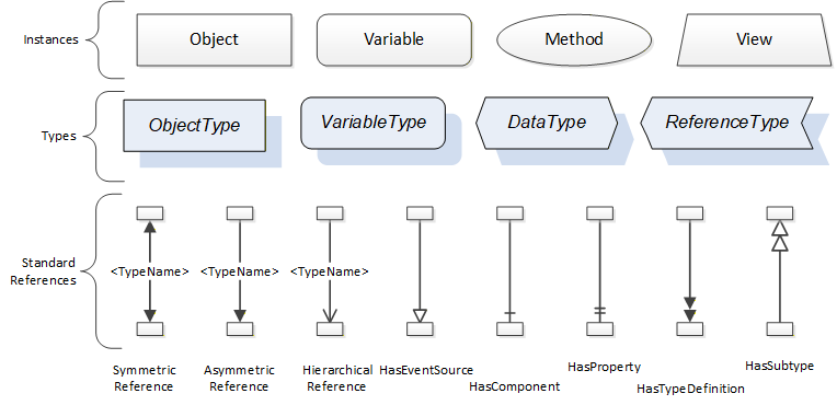
The figures above use a notation that was developed for the OPC UA specification. The notation is summarized in Figure 9. UML representations can also be used; however, the OPC UA notation is less ambiguous because there is a direct mapping from the elements in the figures to Nodes in the AddressSpace of an OPC UA Server.
A complete description of the different types of Nodes and References can be found in OPC 10000-3, and the base structure is described in OPC 10000-5.
OPC UA specification defines a very wide range of functionality in its basic information model. It is not expected that all Clients or Servers support all functionality in the OPC UA specifications. OPC UA includes the concept of Profiles, which segment the functionality into testable certifiable units. This allows the definition of functional subsets (that are expected to be implemented) within a Companion Specification. The Profiles do not restrict functionality but generate requirements for a minimum set of functionalities (see OPC 10000-7).
4.2.3.2 Namespaces
OPC UA allows information from many different sources to be combined into a single coherent AddressSpace. Namespaces are used to make this possible by eliminating naming and ID conflicts between information from different sources. Namespaces in OPC UA have a globally unique 0:String called a NamespaceUri, and a locally unique integer called a NamespaceIndex. The NamespaceIndex is only unique within the context of a Session between an OPC UA Client and an OPC UA Server. The Services defined for OPC UA use the NamespaceIndex to specify the Namespace for qualified values.
There are two types of values in OPC UA that are qualified with Namespaces: NodeIds and QualifiedNames. NodeIds are globally unique identifiers for Nodes. This means the same Node with the same NodeId can appear in many Servers. This, in turn, means Clients can have built in knowledge of some Nodes. OPC UA Information Models generally define globally unique NodeIds for the TypeDefinitions defined by the Information Model.
QualifiedNames are non-localized names qualified with a Namespace. They are used for the BrowseNames of Nodes and allow the same names to be used by different information models without conflict. TypeDefinitions are not allowed to have children with duplicate BrowseNames; however, instances do not have that restriction.
4.2.3.3 Companion Specifications
An OPC UA Companion Specification for an industry specific vertical market describes an Information Model by defining ObjectTypes, VariableTypes, DataTypes and ReferenceTypes that represent the concepts used in the vertical market, and potentially also well-defined Objects as entry points into the AddressSpace.
4.2.4 RelativePath
A RelativePath is a structure that describes a sequence of References and Nodes to follow. Annex A of Part 4 Services describes a text format for a RelativePath that can be used in documentation or in files used to store configuration information
The components of a RelativePath text format are specified in Table 10.
| Symbol | Meaning |
| / | The forward slash character indicates that the Server is to follow any subtype of HierarchicalReferences. |
| . | The period (dot) character indicates that the Server is to follow any subtype of an Aggregates ReferenceType. |
| <[#!ns:]ReferenceType> | A 0:String delimited by the '<' and '>' symbols specifies the BrowseName of a ReferenceType to follow. By default, any References of the subtypes the ReferenceType are followed as well. A '#' placed in front of the BrowseName indicates that subtypes should not be followed. A '!' in front of the BrowseName is used to indicate that the inverse Reference should be followed. The BrowseName may be qualified with a namespace index (indicated by a numeric prefix followed by a colon). This namespace index is used specify the namespace component of the BrowseName for the ReferenceType. If the namespace prefix is omitted, then namespace index 0 is used. |
| [ns:]BrowseName | A 0:String that follows a '/', '.' or '>' symbol specifies the BrowseName of a target Node to return or follow. This BrowseName may be prefixed by its namespace index. If the namespace prefix is omitted, then namespace index 0 is used. Omitting the final BrowseName from a path is equivalent to a wildcard operation that matches all Nodes which are the target of the Reference specified by the path. |
| & | The & sign character is the escape character. It is used to specify reserved characters that appear within a BrowseName. A reserved character is escaped by inserting the '&' in front of it. Examples of BrowseNames with escaped characters are: Received browse path name Resolves to "&/Name_1" "/Name_1" "&.Name_2" ".Name_2" "&:Name_3" ":Name_3" "&&Name_4" "&Name_4" |