This chapter describes examples for motion device systems, motion devices, axes and power trains.
In addition, this chapter contains examples of how to use the references contained in this specification.
Typically a motion device system consists of at least one manipulator and one control unit. Manipulators shown in Figure B.1, Figure B.2, Figure B.3, Figure B.4, Figure B.5, Figure B.6 and Figure B.7 normally have only one control unit.
Figure B.8 shows an example with four motion devices which can be controlled by one control unit.
The motion device system illustrated in Figure B.9 consists of three motion devices and may have one or more control units regarding the motion devices. When a safety PLC is integrated in this motion device system, it can be described as an own instance of a ControllerType. This Instance would have no Reference to an instance of a motion device, because the safety PLC doesn´t control a manipulator. It could however have a Reference to the instantiated SafetyStates.
The motion devices shown in Figure B.8 are typically controlled by one controller unit. Each motion device IsControlledBy the same controller.
The system illustrated in Figure B.9 may have two control units. For example one controller Controls the both articulated robots and the mobile platform IsControlledBy the other controller.
A motion device can be any manipulator e.g. a robot, a linear unit or a turn table. For each motion device which has an own type plate an instance of a MotionDeviceType shall be created.
The kind of motion device shall be described with the Property MotionDeviceCategory of the ParameterSet of the MotionDeviceType by the MotionDeviceCategoryEnumeration, which is based on definitions of ISO 8373:2012.
The Figures Figure B.1(courtesy of KraussMaffei, used with permission) and Figure B.2 (courtesy of KUKA, used with permission) show examples of cartesian manipulators.
Figure B.2 shows a portal manipulator, a variant of a cartesian manipulator. Axis 1 in this example is driven with master-slave and a robot-hand is mounted at the flange of the cartesian manipulator.
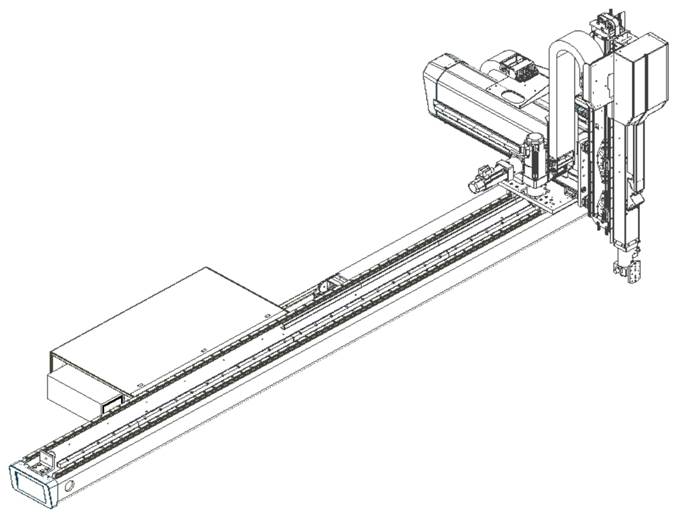
Figure B.1 – Cartesian manipulator
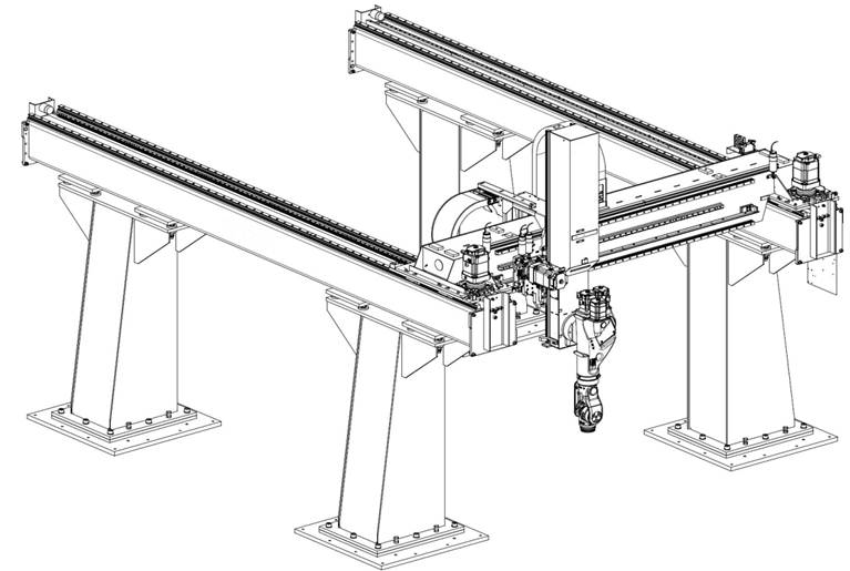
Figure B.2 – Portal manipulator
Figure B.3 (courtesy of Beckhoff used with permission) shows an example of a parallel manipulator. So called delta robots, as shown in Figure B.4 (courtesy of ABB, used with permission), are also parallel manipulators.
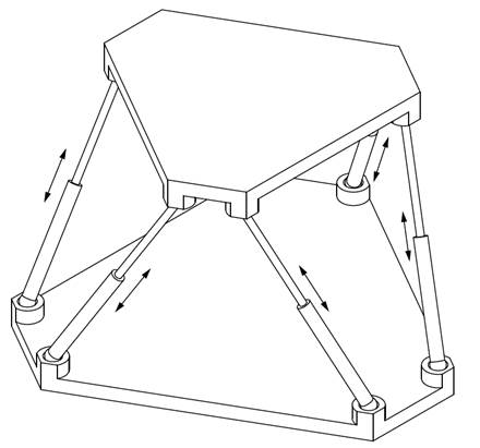
Figure B.3 – Stewart platform or Hexapod
Figure B.4 shows an abstract example of a delta robot.
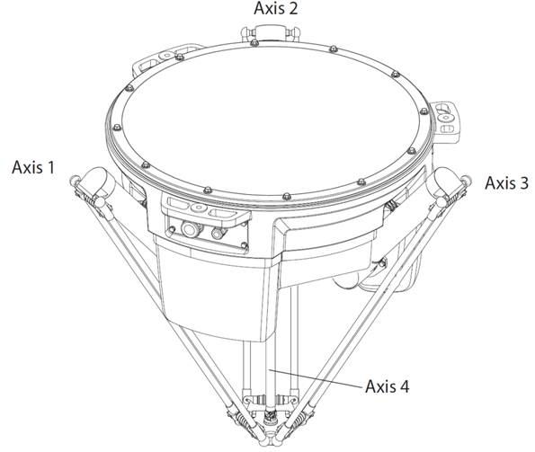
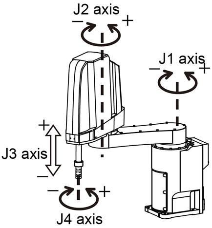
Figure B.5 (Courtesy of Mitsubishi Electric, used with permission) shows an abstract example of a scara robot.
A typical example of an articulated robot is shown in Figure B.6 (courtesy of ABB, used with permission).
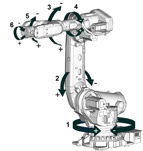
Figure B.6 – Articulated robot
Another example of an articulated robot is a so called humanoid robot as Figure B.7 (courtesy of ABB, used with permission) schematically shows.
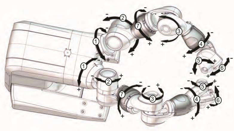
Figure B.7 – Schematic of a humanoid robot
Figure B.8 (courtesy of KUKA, used with permission) shows four motion devices integrated in one motion device system: an articulated robot on a linear unit with two turntables.
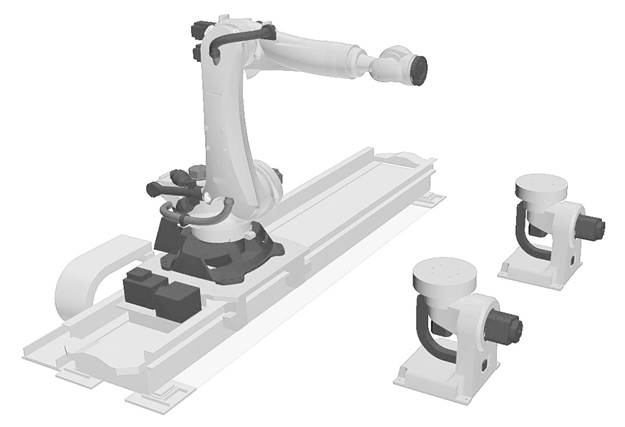
Figure B.8 – Motion device system 1
Figure B.9 (courtesy of KUKA, used with permission) shows three motion devices in one motion device system: two articulated robots on a mobile platform.
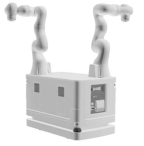
Figure B.9 – Motion device system 2
An axis of a motion device is the mechanical joint of a manipulator that performs a linear or a rotational movement.
Power trains, consisting of gears, motors and drives, are responsible for the movement of axes. Drives can be integrated in the manipulator or inside a controller cabinet. References describe the relationships between the components of the power train.
Figure B.10 shows two possibilities for a realization of a linear two-dimensional motion device. While in the left figure there is a 1:1 relation between power train and mechanical axis in the right figure power train 1 and power train 2 have effect on the movement of axis 1 and on axis 2. An additional load is located on the mechanical axis 2 but has effect on both power trains.
References describe the relationships between the movement of axes and the power trains that initiate the movement.
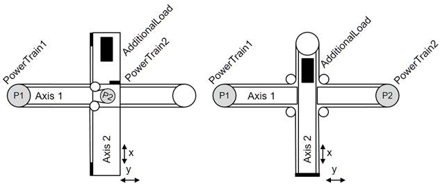
Figure B.10 – Axis and power train coupling
If there is the need to show information about virtual axes, which are not actively run by a power train, then these axes shall be provided, but they don´t have References to a power train. An example for a virtual axis is, when a robot control calculates the movement of an external axis in accordance to the robot movement, e.g. for a servo welding gun mounted at the robot flange, but doesn´t control actively the movement of this axis with an internal power train.
Another example for a virtual axis can be found in a delta robot. When the fourth axis is driven through a telescope shaft and cardan joints, then the length of the telescope shaft is depending on the positions of axes 1, 2 and 3. This length can be seen as a virtual axis, as it has constraints similar to a real axis, e.g. position limits. But it is not possible to actively move this axis.
Figure B.1 and Figure B.2 show different versions of Cartesian robots. Figure B.1 shows a three axis robot which has one dedicated power train for each axis: A power train Moves exactly one axis and so an axis only Requires one dedicated power train. One motor of a power train IsDrivenBy a drive and IsConnectedTo a gear.
Figure B.2 shows a three axis robot with a master-slave driven axis 1. The first and second power train Moves axis 1. The first power train HasSlave the second power train. Axis 1 Requires the first and the second power train. For axis 2 and 3 one power train Moves exactly one axis and so an axis only Requires one dedicated power train.
The typical six-axis industrial robot shown in Figure B.6 normally has 6 power trains for the movement of the 6 axes. Due to the robot hand design, various power trains initiate internal compensation movements. When only the motor of power train 4 is rotating then axis 4, axis 5 and 6 are moving. When only axis 4 should be moved and axis 5 and 6 should stand still then power trains 5 and 6 must compensate the movement of these axes. Thus a movement of only axis 4 requires rotation of the motors of the power trains 4, 5 and 6. The complete set of references is depiced in Figure B.11.
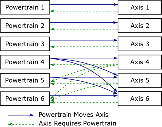
Figure B.11 – Coupling references for a typical six-axis industrial robot
A power train Moves an axis means that if the motor of only this power train moves then there will be an effect on the position of the axis.
- Power train 1 Moves axis 1
- Power train 2 Moves axis 2
- Power train 3 Moves axis 3
- Power train 4 Moves axis 4, axis 5 and axis 6
- Power train 5 Moves axis 5 and axis 6
- Power train 6 Moves axis 6
Description regarding iv.: When only the motor of power train 4 is moving there is an effect on the position of axis 4, axis 5 and axis 6.
An axis IsMovedBy a power trains means, that actions of these power trains have an influence on the axis position. It is the inverse of the Moves reference.
- Axis 1 IsMovedBy power train 1
- Axis 2 IsMovedBy power train 2
- Axis 3 IsMovedBy power train 3
- Axis 4 IsMovedBy power train 4
- Axis 5 IsMovedBy power train 5 and power train 4
- Axis 6 IsMovedBy power train 6, power train 5 and power train 4
Description regarding vi.: Axis 6 movement is depending on movement from power train 6, power train 5 and power train 4.
An axis Requires the movement of a motor of a power train to position but also other power trains might be involved by this movement to compensation movements of affected axes.
- Axis 1 Requires power train 1
- Axis 2 Requires power train 2
- Axis 3 Requires power train 3
- Axis 4 Requires power train 4, power train 5 and power train 6
- Axis 5 Requires power train 5 and power train 6
- Axis 6 Requires power train 6
Description regarding iv.: When only axis 4 should be moved compensation movements of power train 5 and power train 6 are necessary to ensure a standstill of axis 5 and axis 6.
A power train IsRequiredBy axes means that this power train is active when only the referenced axis should be moved and all other axis should stand still. It is the inverse of the Requires reference.
- Power train 1 IsRequiredBy axis 1
- Power train 2 IsRequiredBy axis 2
- Power train 3 IsRequiredBy axis 3
- Power train 4 IsRequiredBy axis 4
- Power train 5 IsRequiredBy axis 4 and axis 5
- Power train 6 IsRequiredBy axis 4, axis 5 and axis 6
Description regarding vi: Power train 6 is involved in positioning of axis 4, axis 5 and axis 6.
A high-payload six-axis industrial robot shown in Figure B.6 can have nine power trains for the movement of the six axes. In this example the axes 1 to 3 are each driven by two power trains with master-slave configuration.
Figure B.12 shows the use of the HasSlave rerference in addition to the power train to axis references.
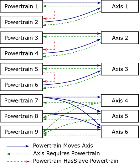
Figure B.12 – Coupling references for a six-axis industrial robot with master-slave axes
A power train HasSlave a power train means that one power train is the master of a master-slave-configuration and he references HasSlave to power train which is slave coupled.
HasSlave References:
- Power train 1 HasSlave power train 2
- Power train 3 HasSlave power train 4
- Power train 5 HasSlave power train 6
For this master-slave configuration the Moves and Requires references :
- Power train 1 Moves axis 1
- Power train 2 Moves axis 1
- Power train 3 Moves axis 2
- Power train 4 Moves axis 2
- Power train 5 Moves axis 3
- Power train 6 Moves axis 3
- Power train 7 Moves axis 4, axis 5 and axis 6
- Power train 8 Moves axis 5 and axis 6
- Power train 9 Moves axis 6
- Axis 1 Requires power train 1 and power train 2
- Axis 2 Requires power train 3 and power train 4
- Axis 3 Requires power train 5 and power train 6
- Axis 4 Requires power train 7, power train 8 and power train 9
- Axis 5 Requires power train 8 and power train 9
- Axis 6 Requires power train 9
For the left motion device in Figure B.10 the References between axes and power trains are shown in Figure B.13.
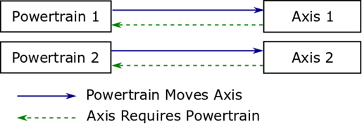
Figure B.13 – Coupling references for a simple linear two-dimensional motion device
Moves References:
Requires Refernces from power train to axis
- Power Train 1 IsRequiredBy axis 1
- Power Train 2 IsRequiredBy axis 2
For the right motion device in Figure B.10 the References between axes and power trains are shown in Figure B.14.
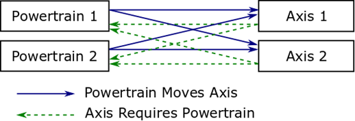
Figure B.14 – Coupling references for linear two-dimensional motion device
Moves References:
Requires Refernces from power train to axis
- Power Train 1 IsRequiredBy axis 1 and axis 2
- Power Train 2 IsRequiredBy axis 1 and axis 2
This chapter descripes different examples for the usage of DriveType or a SubType of ComponentType defined in OPC UA DI inclusive the references described in this specification.
All views show only the instances and references necessary to better illustrate the examples described.
Figure B.15 describes the usage of DriveType as an instance of a single-slot drive regarding the manipulator showed Figure B.10 on the left side.
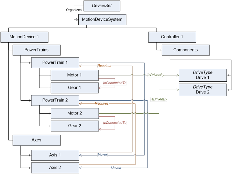
Figure B.15 – IsDrivenby references to DriveType instances
Figure B.16 describes the usage of slots or channels of a multi-slot-drive. The instance ot the slot is a vendor specific subtype of BaseObjectType.
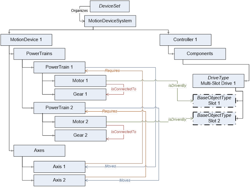
Figure B.16 – IsDrivenby references to vendor specific subtypes of BaseObjectType instances
Figure B.17 describes the usage of DriveType for a multi-slot-drive if deeper information of slot definition is not available.
It is allowed that several instances of MotorType reference IsDrivenBy to one multi-slot-drive.
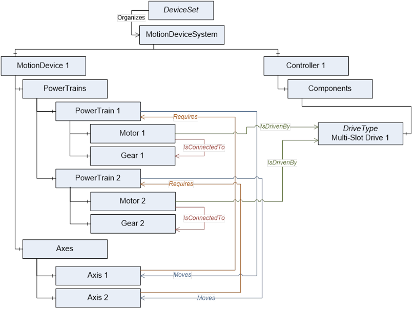
Figure B.17 – IsDrivenby references to DriveType instances for mulit-slot drives w/o slots
Figure B.18 describes the usage with a motor-integrated-drive as one physical device. The instance MyDrive is a vendor specific subtype of BaseObjectType. Identification properties of this physical device shall be defined within the referenced MotorType.
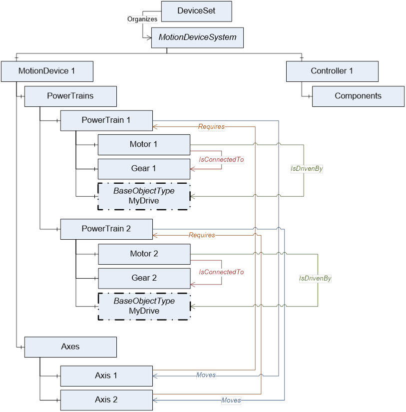
Figure B.18 – IsDrivenby used with motor-integrated-drives
Figure B.19 describes an example view on a server with the instances of ObjectTypes and references of a six-axis robot with master-slave axis and drive-slots described in Annex B.1.8.2.
If a master-slave configuration only has one gear this shall be placed inside the master-power-train.
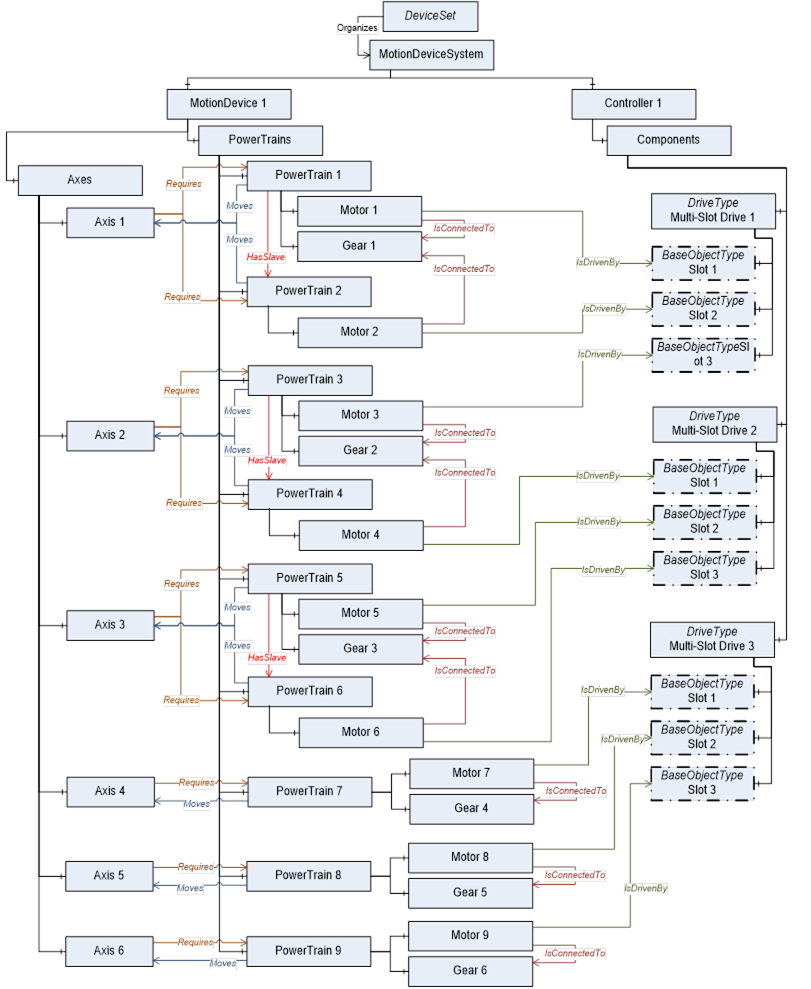
Figure B.19 – View on a six-axis robot with master-slave and drive-slots
Figure B.20 describes an example view on a server with the instances of ObjectTypes and references of a motion device system consisting of a six-axis robot, a linear unit and a turn-table which are controlled by one controller.
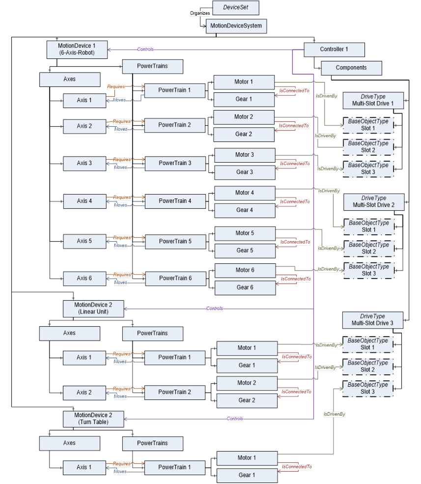
Figure B.20 – View on a motion device system with 3 motion devices controlled by one controller