To show usage of the Constant bit of the Attribute AccessLevelEx, which provides the information about dynamic or static behavior, the figures in Annex C are simplified in the following way (see Figure 12) :
- “Constant” is used for the Constant bit of the AccessLevelEx Attribute of the Variable itself
- “ConstantBase” is used for the Constant bit of the AccessLevelEx Attribute of the Variable Base
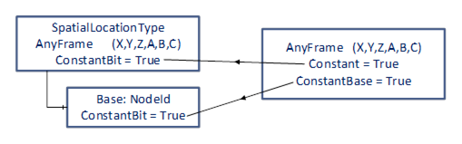
Figure 12 – Convention used for the figures in this Annex
Remark: The Variable Base of instances of SpatialLocationType are shown in the server-instance-examples as green arrows (acting as poor-mans-references) between the instances of CartesianFrameAngleOrientationType, which describe frames.
In the rendered images green coordinate systems define the positions of objects and red coordinate systems define attach points which could be added to objects. The base coordinate-system (WorldFrame) is blue.
An object is extended by the SpatialObject-Addin which provides (see Figure 13):
- Its position regarding a defined coordinate system (WorldFrame):
The green coordinate system at the left foot of the table is the location of the table. It is defined by the PositionFrame of its SpatialObject, which describes the shift related to the WorldFrame.
It is assumed that the table is movable, so the Property Constant this PositionFrame is False. This table is moveable but will always be related to this WorldFrame, so ConstantBase of this PositionFrame is True.
- Attach points of the object where other objects can be geometrically related:
The red coordinate system at the table corner can be defined as an attach-point of the table.
The blue arrow from the foot to the corner of the table shows the displacement (via a frame definition) from the table position to the table corner by the frame TableCorner. The red coordinate system defines the coordinate system of this attach point.
The table is rigid, so table corner does not change its position and so Constant and ConstantBase of this attach-point TableCorner are both True.
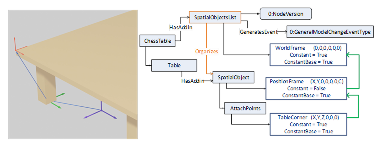
Figure 13 – Table modelled as per the RSL concept
The chess board is an own object (extended with the SpatialObjectType Addin) and is geometrically described with
- its position regarding the attach-point of the table (TableCorner) by its PositionFrame.We assume that the chess board can be moved to another object (e.g. another table), so ConstantBase of the PositionFrame of the Chessboard is False.We assume that the chess board can be displaced on this table, so the Constant of this frame is False.
And the chess board can be brought in relationship to any other object, so the ConstantBase of this frame is False. So, if this chess board should be only moved on the table it might be hard related the table corner, so the ConstantBase would be True.
- possible attach-points of the chess board. All field center positions (red coordinate systems on the right picture in Figure 14) can be described individually (xxCenterAP frames in Figure 15 where xx indicates the field number).
based on the common coordinate system of the chess board (green coordinate system which is described by the chess board PositionFrame relative to the table corner)
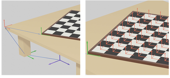
Figure 14 – Table with chessboard containing fields
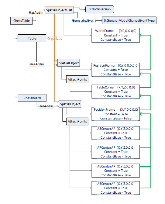
Figure 15 – Table with chessboard modelled as per the RSL concept
The brown knight piece is an own object (extended with the SpatialObjectType Addin) placed on field D7 (Figure 16), is positioned to the coordinate system of field D7 (red coordinate system) by a rotation of angle C counterclockwise in its position frame. (green coordinate system on field C7).
The head of the brown knight piece can be defined as own attach-point, of the figure because this might be a position to pick up this object.
An alternative frame for describing the position of the brown knight provides the knight´s position additionally related to the chess board position (PosToBoard based on the green coordinate system spanned up by the chess board´s PositionFrame).
For this example, the Properties of the PositionFrame of the brown knight are defined as:
- ConstantBase = False, because when the knight is moved to another field the Base may change to the new field.
- Constant = False, because the position and orientation relative to any Base will most likely change with every move.
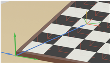
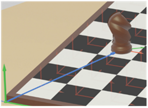
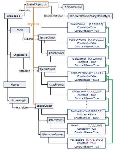
Figure 16 – Figures on the chessboard and their respective modelling with RSL
Note, that the chess pieces on the board are related directly to the chess board and not to fields of the chess board to show the flexibility of this concept.
- In this example (Figure 17) there are no fields on a chess board defined as attach-points. So, the pieces on the board are related directly to the position of the board. So, the position frames of the brown horse, the brown king and the white king include the shift of X, Y and Z additionally to the rotation C (compared to example C.1.3 using attach points for fields of a chess board).
- The PositionFrame of the brown queen is related to the attach point of the table corner
- The white king has an alternative position frame (WorldPosWK yellow) related to the WorldFrame.

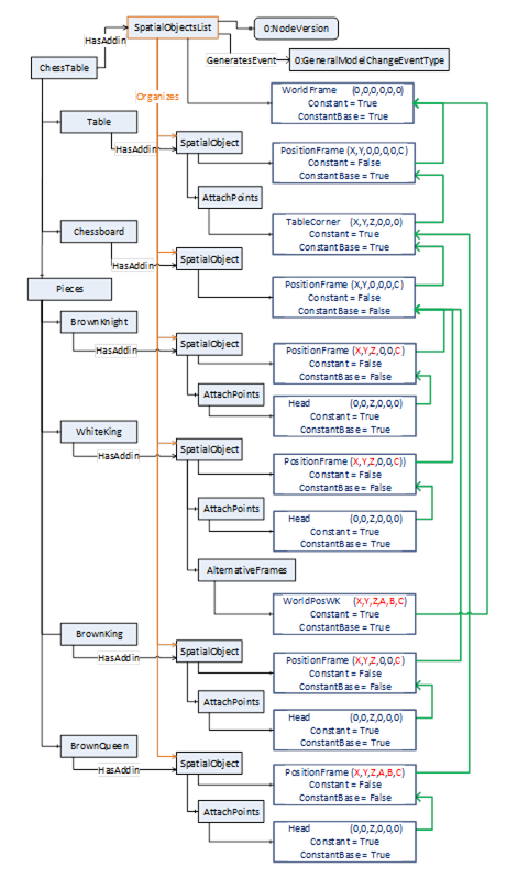
Figure 17 – Model of the table with chessboard, figures on and off the chessboard
Following example address space describes the Spatial Relative Location concept with different objects used in an example industrial application (Figure 18). A robot mounted on a linear unit carrying an exchangeable robot tool. A second tool to change is placed at a change station on a table. Additionally, a tool for the robot is configured and not used in this application scenario (so Variable Base is NULL), but may occur, when brought in spatial relationship to frames SpatialObjects of this SpatialObjectsList.
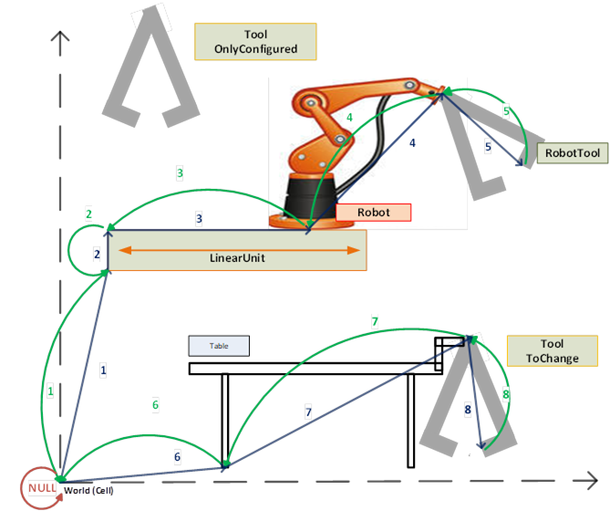
Figure 18 – Objects and their relative positions in an industrial application
Following figure (Figure 19) shows different representations how, for example, the SpatialObject of the LinearUnit can be described
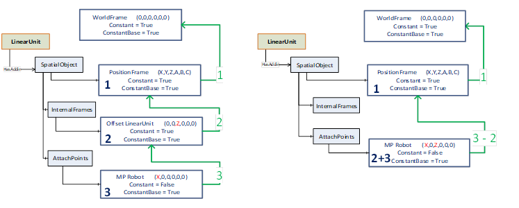
Figure 19 – Possible representations of the linear unit from the previous example
Following figure (Figure 20) shows an example address space for an automation cell as shown in Figure 18
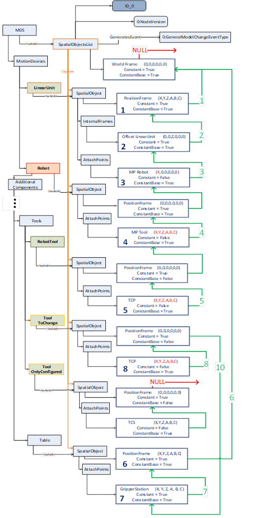
Figure 20 – Modelling of the example scenario using RSL concept
For the use in multi-server scenarios with different servers it might be needed to identify all related SpatialObjectsLists and bring them in relationship in a higher levelled SpatialObjectsList. For this the Property Identifier of a SpatialObjectsList can be instantiated as the Property Identifier of a SpatialObject contained in a higher-level SpatialObjectsList.
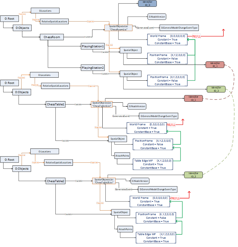
Figure 21 – Usage of the RSL concept in a multi-server scenario
Figure 22 shows an aggregating server, which aggregates all servers illustrated in Figure 21.
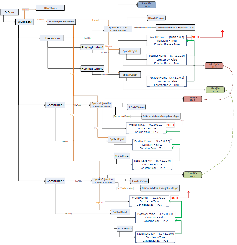
Figure 22 – Usage of the RSL concept in an aggregation scenario
A lot of devices within an automation cell are running geometrically based on a common base frame definition.
At the setup of the automation-cell the Property Identifier might be used for a common cell-id to support the usage of the Relative Spatial Location concept in different devices using a common base coordinate system (Figure 23).
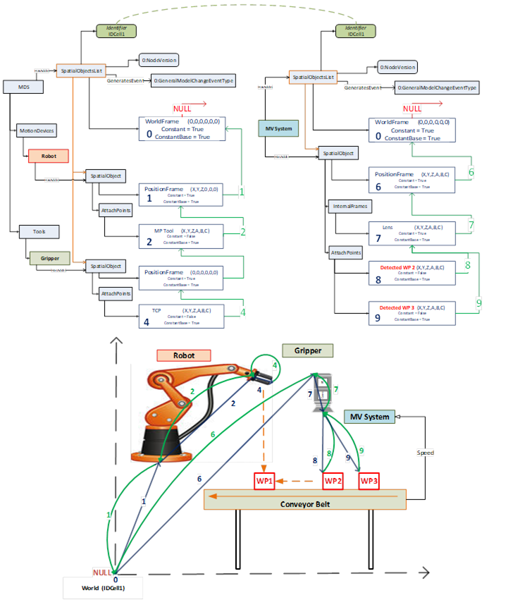
Figure 23 – Example usage of Identifier Property for systems with a common base coordinate system