The following sections define the basic OPC UA Objects defined by MDIS. This includes Method definition as needed. The use cases / object interactions for each Object are defined in a separate section.
The MDISBaseObjectType (see 6.2) is a base object that all other MDIS objects are constructed from. It is an abstract ObjectType and instances of it shall not exist. This Object will be used to create subtypes.
The MDISDiscreteInstrumentObjectType (see 6.3) is a base type and can be subtyped or instances of it can be directly created. The Object can be used with multi-state type of data (stopped, moving, faulted). It could also be used for instruments that report integer values. For a limit switch or on / off switch the MDISDigitalInstrumentObjectType should be used.
The MDISDiscreteOutObjectType (see 6.3.4) is a subtype of MDISDiscreteInstrumentObjectType and can be subtyped or instance of it can be directly created. The Object can be used for Tristate or Multistate switches.
The MDISDiscreteArbitrationObjectType (see 6.3.6) is a subtype of MDISDiscreteInstrumentObjectType and can be subtyped or instance of it can be directly created. It adds inputs that can be selected according to the arbitration mode.
The MDISDigitalInstrumentObjectType (see 6.4) is a base type and can be subtyped or instance of it can be directly created. The Object can be used to represent on / off type of functions.
The MDISDigitalOutObjectType (see 6.4.4) is a subtype of MDISDigitalInstrumentObjectType and can be subtyped or instance of it can be directly created. The Object can be used for switching on / off types.
The MDISDigitalArbitrationObjectType (see 6.4.6) is a subtype of MDISDigitalInstrumentObjectType and can be subtyped or instance of it can be directly created. It adds inputs that can be selected according to the arbitration mode.
The MDISInstrumentObjectType (see 6.5.3) is a base type and can be subtyped or instances of it can be directly created. The Object can be used for various types of analogues, e.g. pressure, temperatures, tank levels etc.
The MDISInstrumentOutObjectType (see 6.5.4) is a subtype of MDISInstrumentObjectType and can be subtyped or instance of it can be directly created. The Object can be used for writing floating point values.
The MDISInstrument ArbitrationObjectType (see 6.5.6) is a subtype of MDISInstrumentObjectType and can be subtyped or instance of it can be directly created. It adds inputs that can be selected according to the arbitration mode.
The MDISChokeObjectType (see 6.6.3) is a base type and can be subtyped or an instance of it can be directly created. A choke is a device that restricts the flow of a fluid (gases, liquids, fluidised solids, or slurries).
The MDISElectricChokeObjectType (see 6.7.3) is a base type and can be subtyped or an instance of it can be directly created. An electric choke is a device that restricts the flow of a fluid (gases, liquids, fluidised solids, or slurries) and can be positioned more precisely than a standard Choke.
The MDISValveObjectType (see 6.8.3) is a base type and can be subtyped or an instance of it can be directly created. A valve is a device that directs or controls the flow of a fluid (gases, liquids, fluidised solids, or slurries). The MDISValveObjectType represents a two-state valve type.
The MDISCIMVObjectType (see 6.9.3) is a base type and can be subtyped or an instance of it can be directly created. The CIMV (Chemical Injection Metering Valve) is used to regulate the flow of chemicals to a well. It can report optional housekeeping data.
The MDISMotorObjectType (see 6.11.3) is a base type and can be subtyped or an instance of it can be directly created. A motor is a device that is used to power pump
The MDISAggregateObjectType (see 6.12.2) is an abstract type that all aggregate ObjectTypes shall be derived from. This ObjectType allows Clients to easily identify aggregate Objects. For more information about aggregation see 10.5
The MDISCounterObjectType (see 6.10.3) is a base type, it is not envisioned that this object will be subtyped, but rather that this object is used as part of other aggregate objects. It provides the capability of resetting counters to some initial value.
The MDISTimeSyncObjectType (see 6.13.3) is a base ObjectType. An instance of this ObjectType shall be exposed as part of the MDISInformationObjectType, if the MDISTimeSyncObjectType is supported.
The MDISInformationObjectType (see 6.14) is a base ObjectType. An instance of this ObjectType shall be exposed under the Objects folder. It provides information about the MDIS Information model that is supported by the Server. It can also expose additional information related to MDIS.
The following section details the MDIS generic properties for the MDISBaseObjectType. Implementations shall ensure adherence to Mandatory [M] aspects in order to comply with the MDIS interface standardisation. Optional [O] may or may not be implemented within a project. Figure 9 provides an overview of the MDISBaseObjectType as defined by MDIS. This Object is intended to be the base object for all other MDIS ObjectTypes (see Figure 10 for an overview of inherited types)
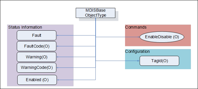
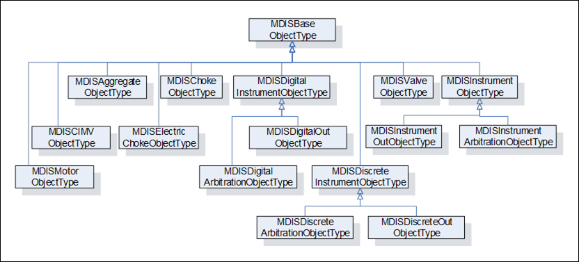
Figure 10 – Base Object Hierarchy
The Table 4 defines the structure of an MDISBaseObjectType.
Table 4 – MDISBaseObjectType Definition
|
Attribute |
Value |
||||
|
BrowseName |
MDISBaseObjectType |
||||
|
IsAbstract |
True |
||||
|
References |
Node Class |
BrowseName |
Data Type |
TypeDefinition |
Other |
|
Subtype of the 0:BaseObjectType defined in OPC 10000-5 |
|
||||
|
0:HasComponent |
Variable |
Fault |
0:Boolean |
0:BaseDataVariableType |
M, RO |
|
0:HasComponent |
Variable |
Warning |
0:Boolean |
0:BaseDataVariableType |
O, RO |
|
0:HasComponent |
Variable |
Enabled |
0:Boolean |
0:BaseDataVariableType |
O, RO |
|
0:HasProperty |
Variable |
TagId |
0:String |
0:PropertyType |
O, RO |
|
0:HasComponent |
Method |
EnableDisable |
See 6.2.3 |
O |
|
|
0:HasComponent |
Variable |
FaultCode |
0:UInt32 |
0:BaseDataVariableType |
O, RO |
|
0:HasComponent |
Variable |
WarningCode |
0:UInt32 |
0:BaseDataVariableType |
O, RO |
|
|
|
|
|
|
|
|
0:HasSubtype |
ObjectType |
MDISDigitalInstrumentObjectType |
|
||
|
0:HasSubtype |
ObjectType |
MDISDiscreteInstrumentObjectType |
|
||
|
0:HasSubtype |
ObjectType |
MDISChokeObjectType |
|
||
|
0:HasSubtype |
ObjectType |
MDISElectricChokeObjectType |
|
||
|
0:HasSubtype |
ObjectType |
MDISInstrumentObjectType |
|
||
|
0:HasSubtype |
ObjectType |
MDISValveObjectType |
|
||
|
0:HasSubtype |
ObjectType |
MDISCIMVObjectType |
|
||
|
0:HasSubtype |
ObjectType |
MDISMotorObjectType |
|
||
|
0:HasSubtype |
ObjectType |
MDISAggregateObjectType |
|
||
|
ConformanceUnits |
|||||
|
MDIS Base Fault |
|||||
The RW column indicates if a Node of Variable NodeClass is readable, writeable or both readable and writeable. Other NodeClasses (Object, Method) do not support reading or writing and do not fill in this column.
By definition a Profile can require that an Optional item be provided, it cannot change the behaviour of an Object from what is described in this specification, which includes support for any Mandatory items. Profiles are described in section 14.3.
Fault – The status of the object, true if any fault exists.
Warning – The status of the object, true if any warnings exist. A warning does not require immediate operator action.
Enabled – This Variable is set as enabled (true) by default. When disabled the Object will not report any dynamic information other than a bad status code (Bad_InvalidState). It will still report configuration related information. It will disable execution of any method that might be defined as part of the Object. For the MDISBaseObjectType the default is that only the Enabled flag, TagId and EnableDisable Method report values or perform functions. Subtypes of this ObjectType may describe additional requirements for disabled Objects.
TagId – The TagId is a unique equipment identifier. This is additional information that can be used to help identify the Variable associated with the instance of this type. This field is intended to be used to store the tag id from the P&ID.
EnableDisable – This Method allows a Client to disable or enable the Object.
FaultCode – An unsigned integer that describes a fault code(s), zero indicates no fault. The FaultCode is a 32 bit mask, with 16 bits for standard defined codes and 16 bits for vendor defined codes. Each of the Subtypes of this ObjectType defined in this specification shall define a set standard FaultCodes that apply to that ObjectType (bits 0-15). In addition, the SPCS vendor may provide vendor specific bits (bits 16-31). Once a Bit is defined (given a name), then in all Objects that use that same named fault, the same bit number is used.
WarningCode – An unsigned integer that describes a warning code(s), zero indicates no warning. The SPCS vendor will provide a definition of what the number means The WarningCode is a 32 bit mask, with 16 bits for standard defined codes and 16 bits for vendor defined codes. Each of the subtypes of this ObjectType defined in this specification shall define a set standard WarningCodes that apply to that ObjectType (bits 0-15). In addition, the SPCS vendor may provide vendor specific bits (bits 16-31). Once a Bit is defined (given a name), then in all Objects that use that same named warning, the same bit number is used.
EnableDisable is used to disable or enable an Object. The enable / disable operation applies to the Object in the UA Server. The call completes when the enable / disable operation is complete. The Server may or may not pass the enable / disable down to lower levels. This is Server specific behaviour.
Signature
EnableDisable (
[in] 0:Boolean Enable );
Table 5 – EnableDisable Method parameters
|
Argument |
Description |
|
Enable |
Boolean indicator of whether the Object is to be disabled or enabled. A true indicates that the Object is enabled. |
Method result codes are defined as part of the Call Service (see OPC 10000-4). They are described in Table 124 for ease of reference.
Comments
The EnableDisable Method will disable or enable this Object. Once the state of an Object is changed by this Method (i.e., disabled) the state will be maintained until this Method is called again to change the state (i.e., enable). The Method will report if any error occurs while disabling or enabling the Object. Table 6 specifies the AddressSpace representation for the EnableDisable Method.
Table 6 – EnableDisable Method AddressSpace Definition
|
Attribute |
Value |
||||
|
BrowseName |
EnableDisable |
||||
|
References |
Node Class |
BrowseName |
DataType |
TypeDefinition |
Other |
|
0:HasProperty |
Variable |
0:InputArguments |
0:Argument[] |
0:PropertyType |
M |
|
ConformanceUnits |
|||||
|
MDIS Base Enabled |
|||||
The following section details the generic MDISDiscreteInstrumentObjectType structure and defines the properties associated with it. Additional sections define a subtype MDISDiscreteOutObjectType that allows updates to the discrete value. This is in general a vendor and operator independent description, but all users of the MDISDiscreteInstrumentObjectType or MDISDiscreteOutObjectType can add vendor specific data. The vendor specific data should be defined as part of a subtype of the MDISDiscreteInstrumentObjectType or MDISDiscreteOutObjectType defined in this document. It is assumed that the subsea system is the Server and host of the instance of the MDISDiscreteInstrumentObjectType or MDISDiscreteOutObjectType. The DCS based system is the Client in the system. It is assumed that all interactions with the instance of the MDISDiscreteInstrumentObjectType are initiated by the Client and are directed to the Server.
The following section details the MDIS generic properties for the MDISDiscreteInstrumentObjectType. Implementation shall ensure adherence to Mandatory [M] aspects in order to comply with the MDIS interface standardisation. Optional [O] may or may not be implemented within a project. Figure 11 provides an overview of the MDISDiscreteInstrumentObjectType as defined by MDIS, including some nested types. This figure includes all items that are inherited from the MDISBaseObjectType.
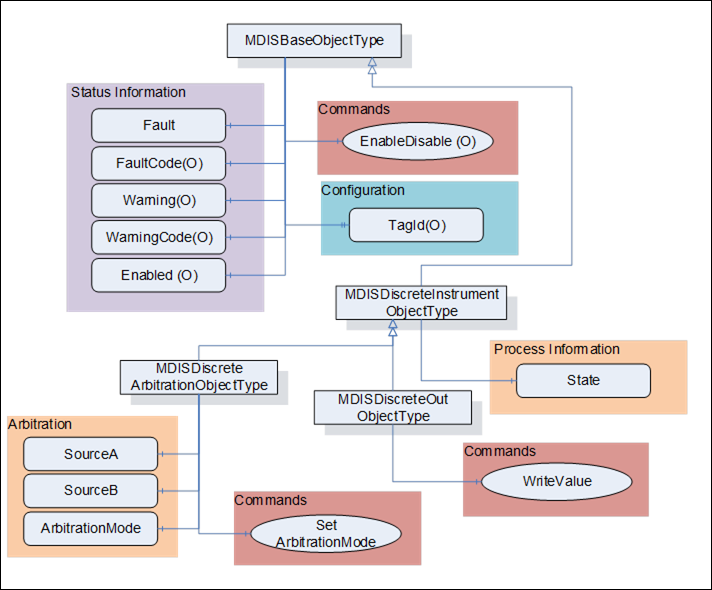
Figure 11 – MDISDiscreteInstrumentObjectType & MDISDiscreteOutObjectType & MDISDiscreteArbitrationObjectType
Table 7 defines the structure of an MDISDiscreteInstrumentObjectType. Any vendor specified properties that have been implemented within a project should be documented within a similar format and supplied to the DCS vendor. The addition of vendor specific properties will result in a subtype of the MDISDiscreteInstrumentObjectType.
Table 7 – MDISDiscreteInstrumentObjectType Definition
|
Attribute |
Value |
||||
|
BrowseName |
MDISDiscreteInstrumentObjectType |
||||
|
IsAbstract |
False |
||||
|
References |
Node Class |
BrowseName |
DataType |
TypeDefinition |
Other |
|
Subtype of the MDISBaseObjectType (see section 6.1.1) |
|
||||
|
0:HasComponent |
Variable |
State |
0:UInt32 |
0:BaseDataVariableType |
M, RO |
|
0:HasSubtype |
ObjectType |
MDISDiscreteOutObjectType |
|||
|
0:HasSubtype |
ObjectType |
MDISDiscreteArbitrationObjectType |
|||
|
ConformanceUnits |
|||||
|
MDIS Discrete Instrument Base |
|||||
State – The state of the instance of MDISDiscreteInstrumentObjectType. This state is represented as a UInt32.
The MDISDiscreteInstrumentObjectType is a subtype of MDISBaseObjectType and inherits the FaultCode Variable. The MDISDiscreteInstrumentObjectType defines the standard FaultCodes (for bits 0-15 as defined in 6.2.2) in Table 8. All subtypes of this the MDISDiscreteInstrumentObjectType will inherit all FaultCodes defined in this table. Subtypes may define additional FaultCodes in their own table.
Table 8 – MDISDiscreteInstrumentObjectType FaultCode Values
|
Value |
Bit no. |
Description |
|
IOFault |
0 |
Instrument has no usable value, there is an I/O fault. |
The MDISDiscreteInstrumentObjectType defines the standard WarningCodes (for bits 0-15 as defined in 6.2.2) in Table 9. All subtypes of this the MDISDiscreteInstrumentObjectType will inherits all WarningCodes defined in this table. Subtypes may define additional WarningCodes in their own table.
Table 9 – MDISDiscreteInstrumentObjectType WarningCode Values
|
Value |
Bit no. |
Description |
|
SideAProblem |
0 |
There is an issue with the A side of this instrument [note this only applies to instrument that are arbitrated] |
|
SideBProblem |
1 |
There is an issue with the B side of this instrument [note this only applies to instrument that are arbitrated] |
|
Discrepancy |
2 |
The values differ by more than is acceptable |
Table 10 defines the structure of an MDISDiscreteOutObjectType. Any vendor specified properties that have been implemented within a project should be documented within a similar format and supplied to the DCS vendor. The addition of vendor specific properties will result in a subtype of the MDISDiscreteOutObjectType.
Table 10 – MDISDiscreteOutObjectType Definition
|
Attribute |
Value |
||||
|
BrowseName |
MDISDiscreteOutObjectType |
||||
|
IsAbstract |
False |
||||
|
References |
Node Class |
BrowseName |
DataType |
TypeDefinition |
Other |
|
Subtype of the MDISDiscreteInstrumentObjectType (see section 6.1.2) |
|
||||
|
0:HasComponent |
Method |
WriteValue |
See 6.3.5 |
M |
|
|
ConformanceUnits |
|||||
|
MDIS Discrete Out Base |
|||||
WriteValue – This Method allows a Client to change the value of State on an instance of MDISDiscreteOutObjectType. The Method will return any errors that occurred on setting the value. The Client shall verify that the State actually changed to confirm the update. If the instrument is disabled, an error Bad_InvalidState shall be returned.
WriteValue Method (defined in Table 11) is used to change the value of the State Variable in an instance of MDISDiscreteOutObjectType. The WriteValue operation applies to the object in the subsea system. The value of the State Variable shall only be updated once the subsea system has provided a new value. For Objects that are used as a command, the value of the State Variable shall be updated directly to the value provided by the State parameter of the Method. Some systems will be able to report any errors immediately others will only be able to report that the operation was not refused. Clients are expected to monitor the State and ensure that the operation completed. If an error occurs after the Method has returned, a Fault flag shall be set and an appropriate FaultCode will be returned. The Fault (and FaultCode) will reset on the next successful WriteValue Method invocation.
Signature:
WriteValue (
[in] 0:UInt32 State);
Table 11 – WriteValue Method parameters
|
Argument |
Description |
|
State |
UInt32 value Variable, that indicates the target state of the Variable |
Method result codes are defined as part of the Call Service (see OPC 10000-4). They are described in Table 124 for ease of reference.
Comments
The WriteValue Method will result in a change the value of the State Variable. The Method will report if any error occurs while writing the state of the Object. Table 12 specifies the AddressSpace representation for the WriteValue Method.
Table 12 – WriteValue Method AddressSpace Definition
|
Attribute |
Value |
|||||
|
BrowseName |
WriteValue |
|||||
|
References |
Node Class |
BrowseName |
DataType |
TypeDefinition |
Other |
|
|
0:HasProperty |
Variable |
InputArguments |
Argument[] |
0:PropertyType |
M |
|
|
ConformanceUnits |
||||||
|
MDIS Discrete Out Base |
||||||
Table 13 defines the structure of an MDISDiscreteArbitrationObjectType. Any vendor specified properties that have been implemented within a project should be documented within a similar format and supplied to the DCS vendor. The addition of vendor specific properties will result in a subtype of the MDISDiscreteArbitrationObjectType.
Table 13 – MDISDiscreteArbitrationObjectType Definition
|
Attribute |
Value |
||||
|
BrowseName |
MDISDiscreteArbitrationObjectType |
||||
|
IsAbstract |
False |
||||
|
References |
Node Class |
BrowseName |
DataType |
TypeDefinition |
Other |
|
Subtype of the MDISDiscreteInstrumentObjectType |
|
||||
|
0:HasComponent |
Variable |
SourceA |
0:UInt32 |
0:BaseDataVariableType |
M, RO |
|
0:HasComponent |
Variable |
SourceB |
0:UInt32 |
0:BaseDataVariableType |
M, RO |
|
0:HasComponent |
Variable |
ArbitrationMode |
ArbitrationModeEnum |
0:BaseDataVariableType |
M, RO |
|
0:HasComponent |
Method |
SetArbitrationMode |
Defined in section 6.3.7 |
O |
|
|
ConformanceUnits |
|||||
|
MDIS Discrete Arbitration |
|||||
The MDISDiscreteArbitrationObjectType will select which instrument is healthy and report it. The arbitration object selects between the two sources, SourceA and SourceB base on the source and the selected ArbitrationMode. The result of the arbitration is shown in the State. The result can be either a selection of one source as default or forcing of one source (see 8.1.10 for additional details).
SourceA – a Variable that represents the value of the first source of a MDISDiscreteArbitrationObjectType.
SourceB – a Variable that represents the value of the second source of a MDISDiscreteArbitrationObjectType
ArbitrationMode – This enumeration provides information about the ArbitrationMode that is currently used (see section 8.1.10). The Average enumeration value does not apply to this arbitration ObjectType.
The MDISDiscreteArbitrationObjectType is a subtype of MDISDiscreteInstrumentObjectType and inherit the FaultCode Variable. The MDISDiscreteArbitrationObjectType defines the standard FaultCodes (for bits 0-15 as defined in 6.2.2) in Table 14 (currently empty, no additional fault codes defined). All subtypes of this the MDISDiscreteArbitrationObjectType will inherit all FaultCodes defined in this table. Subtypes may define additional FaultCodes in their own table.
Table 14 – MDISDiscreteArbitrationObjectType FaultCode Values
|
Value |
Bit no. |
Description |
|
|
|
|
The MDISDiscreteArbitrationObjectType defines the standard WarningCodes (for bits 0-15 as defined in 6.2.2) in Table 15 (currently empty, no additional warning codes defined). All subtypes of this the MDISDiscreteArbitrationObjectType will inherit all WarningCodes defined in this table. Subtypes may define additional WarningCodes in their own table.
Table 15 – MDISDiscreteArbitrationObjectType WarningCode Values
|
Value |
Bit no. |
Description |
|
|
|
|
SetArbitrationMode Method is used to change the arbitration strategy of the arbitration Object. If the mode cannot be changed the method shall return an error. This description applies to the following arbitration objects (MDISDigitalArbitrationObjectType, MDISDiscreteArbitrationObjectType, MDISInstrumentArbitrationObjectType).
Signature:
SetArbitrationMode (
[in] ArbitrationModeEnum ArbitrationMode);
Table 16 – SetArbitrationMode Method parameters
|
Argument |
Description |
|
ArbitrationMode |
ArbitrationMode enumeration value Variable, that defines the new arbitration mode, see 8.1.10 |
Method result codes are defined as part of the Call Service (see OPC 10000-4). They are described in Table 124 for ease of reference. The following specific Method result codes are defined in Table 17.
Table 17 – SetArbitrationMode Method result codes
|
ResultCode |
Description |
|
Bad_NotSupported |
The requested arbitration mode is not supported. |
Comments
The SetArbitrationMode Method will change the arbitration strategy. The Method will report if any error which occur while writing the value of the Object. Table 18 specifies the AddressSpace representation for the SetArbitrationMode Method.
Table 18 – SetArbitrationMode Method AddressSpace Definition
|
Attribute |
Value |
||||
|
SetArbitrationMode |
|||||
|
References |
Node Class |
DataType |
TypeDefinition |
Other |
|
|
0:HasProperty |
Variable |
0:InputArguments |
0:Argument[] |
0:PropertyType |
M |
|
ConformanceUnits |
|||||
|
MDIS Discrete Arbitration |
|||||
|
MDIS Digital Arbitration |
|||||
|
MDIS Instrument Arbitration Base |
|||||
The following section describes the generic MDISDigitalInstrumentObjectType structure and defines the properties associated with it. Additional sections define a subtype MDISDigitalOutObjectType that allows updates to the digital value. This is in general a vendor and operator independent description, but all users of the MDISDigitalInstrumentObjectType or MDISDigitalOutObjectType can add vendor specific data. The vendor specific data should be defined as part of a subtype of the MDISDigitalInstrumentObjectType or MDISDigitalOutObjectType defined in this document. It is assumed that the subsea system is the Server and host of the instance of MDISDigitalInstrumentObjectType or MDISDigitalOutObjectType. The DCS based system is the Client in the system. It is assumed that all interactions with the instance of the MDISDigitalInstrumentObjectType are initiated by the Client and are directed to the Server.
The following section details the MDIS generic properties for the MDISDigitalInstrumentObjectType; implementation shall ensure adherence to Mandatory [M] aspects in order to comply with the MDIS interface standardisation. Optional [O] may or may not be implemented within a project.
Figure 12 provides an overview of the MDISDigitalInstrumentObjectType as defined by MDIS, including some nested types. This figure includes all items that are inherited from the MDISBaseObjectType.
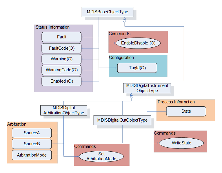
Figure 12 – MDISDigitalInstrumentObjectType & MDISDigitalOutObjectType & MDISDigitalArbitrationObjectType
Table 19 defines the structure of an MDISDigitalInstrumentObjectType. Any vendor specified properties that have been implemented within a project should be documented within a similar format and supplied to the DCS vendor. The addition of vendor specific properties will result in a subtype of the MDISDigitalInstrumentObjectType.
Table 19 – MDISDigitalInstrumentObjectType Definition
|
Attribute |
Value |
||||
|
BrowseName |
MDISDigitalInstrumentObjectType |
||||
|
IsAbstract |
False |
||||
|
References |
Node Class |
BrowseName |
DataType |
TypeDefinition |
Other |
|
Subtype of the MDISBaseObjectType (see section 6.1.1) |
|
||||
|
0:HasComponent |
Variable |
State |
0:Boolean |
0:BaseDataVariableType |
M, RO |
|
0:HasSubtype |
ObjectType |
MDISDigitalOutObjectType |
|
||
|
0:HasSubtype |
ObjectType |
MDISDigitalArbitrationObjectType |
|
||
|
ConformanceUnits |
|||||
|
MDIS Digital Instrument Base |
|||||
State – The state of the instance of MDISDigitalInstrumentObjectType. This state is represented as a Boolean, where true indicates on and false indicates off.
The MDISDigitalInstrumentObjectType is a subtype of MDISBaseObjectType and inherit the FaultCode Variable. The MDISDigitalInstrumentObjectType defines the standard FaultCodes (for bits 0-15 as defined in 6.2.2) in Table 8. All subtypes of this the MDISDigitalInstrumentObjectType will inherit all FaultCodes defined in this table. Subtypes may define additional FaultCodes in their own table.
Table 20 – MDISDigitalInstrumentObjectType FaultCode Values
|
Value |
Bit no. |
Description |
|
IOFault |
0 |
Instrument has no usable value, there is an I/O fault. |
The MDISDigitalInstrumentObjectType defines the standard WarningCodes (for bits 0-15 as defined in 6.2.2) in Table 9. All subtypes of this the MDISDigitalInstrumentObjectType will inherit all WarningCodes defined in this table. Subtypes may define additional WarningCodes in their own table.
Table 21 – MDISDigitalInstrumentObjectType WarningCode Values
|
Value |
Bit no. |
Description |
|
SideAProblem |
0 |
There is an issue with the A side of this instrument [note this only applies to instrument that are arbitrated] |
|
SideBProblem |
1 |
There is an issue with the B side of this instrument [note this only applies to instrument that are arbitrated] |
|
Discrepancy |
2 |
The values differ [note this only applies to instrument that are arbitrated] |
Table 22 defines the structure of an MDISDigitalOutObjectType. Any vendor specified properties that have been implemented within a project should be documented within a similar format and supplied to the DCS vendor. The addition of vendor specific properties will result in a subtype of the MDISDigitalOutObjectType.
Table 22 – MDISDigitalOutObjectType Definition
|
Attribute |
Value |
||||
|
BrowseName |
MDISDigitalOutObjectType |
||||
|
IsAbstract |
False |
||||
|
References |
Node Class |
BrowseName |
DataType |
TypeDefinition |
Other |
|
Subtype of the MDISDigitalInstrumentObjectType |
|
||||
|
0:HasComponent |
Method |
WriteState |
See 6.4.5 |
M |
|
|
ConformanceUnits |
|||||
|
MDIS Digital Out Base |
|||||
WriteState – This Method allows a Client to change the value of State on an instance of MDISDigitalOutObjectType. The Method will return any errors that occurred on setting the value. The Client shall verify that the State actually changed to confirm the update. If the instrument is disabled, an error Bad_InvalidState shall be returned.
WriteState Method (defined in Table 23) is used to change the state of the State Variable in an instance of MDISDigitalOutObjectType. The WriteState operation applies to the object in the subsea system. The value of the State Variable shall only be updated once the subsea system has provided a new value. For Objects that are used as a command, the value of the State Variable shall be updated directly to the value provided by the State parameter of the Method. Some systems will be able to report any errors immediately others will only be able to report that the operation was not refused. Clients are expected to monitor the State and ensure that the operation completed. If an error occurs after the Method has returned, a Fault flag shall be set and an appropriate FaultCode will be returned. The Fault (and FaultCode) will reset on the next successful WriteState Method invocation.
Signature:
WriteState (
[in] 0:Boolean State);
Table 23 – WriteState Method parameters
|
Argument |
Description |
|
State |
Boolean indicator of the target state of the variable |
Method result codes are defined as part of the Call Service (see OPC 10000-4). They are described in Table 124 for ease of reference.
Comments
The WriteState Method will result in a change the state of the State Variable. The Method will report if any error occurs while writing the state of the Object. Table 24 specifies the AddressSpace representation for the WriteState Method.
Table 24 – WriteState Method AddressSpace Definition
|
Attribute |
Value |
||||
|
BrowseName |
WriteState |
||||
|
References |
Node Class |
BrowseName |
DataType |
TypeDefinition |
Other |
|
0:HasProperty |
Variable |
0:InputArguments |
0:Argument[] |
0:PropertyType |
M |
|
ConformanceUnits |
|||||
|
MDIS Digital Out Base |
|||||
Table 25 defines the structure of an MDISDigitalArbitrationObjectType. Any vendor specified properties that have been implemented within a project should be documented within a similar format and supplied to the DCS vendor. The addition of vendor specific properties will result in a subtype of the MDISDigitalArbitrationObjectType.
Table 25 – MDISDigitalArbitrationObjectType Definition
|
Attribute |
Value |
||||
|
BrowseName |
MDISDigitalArbitrationObjectType |
||||
|
IsAbstract |
False |
||||
|
References |
Node Class |
BrowseName |
DataType |
TypeDefinition |
Other |
|
Subtype of the MDISDigitalInstrumentObjectType |
|
||||
|
0:HasComponent |
Variable |
SourceA |
0:Boolean |
0:BaseDataVariableType |
M, RO |
|
0:HasComponent |
Variable |
SourceB |
0:Boolean |
0:BaseDataVariableType |
M, RO |
|
0:HasComponent |
Variable |
ArbitrationMode |
ArbitrationModeEnum |
0:BaseDataVariableType |
M, RO |
|
0:HasComponent |
Method |
SetArbitrationMode |
Defined in 6.3.7 |
O |
|
|
ConformanceUnits |
|||||
|
MDIS Digital Arbitration |
|||||
The MDISDigitalArbitrationObjectType handles the Selection of two analog sources, SourceA and SourceB. The result of the arbitration is shown in the State. The result can be either a selection of one source as default or forcing of one source (see ArbitrationModeEnum for additional details). The arbitration object will select which instrument is healthy and report it.
SourceA – a Variable that represents the value of the first source of a MDISDigitalArbitrationObjectType.
SourceB – a Variable that represents the value of the second source of a MDISDigitalArbitrationObjectType.
ArbitrationMode – This enumeration provides information about the arbitration mode that is currently used (see section 8.1.10). For a MDISDigitalArbitrationObjectType, the average value does not apply and the High value indicates an “Or” of the two values while a low value indicates an “And’ of the two values.
The MDISDigitalArbitrationObjectType is a subtype of MDISDigitalInstrumentObjectType and inherits the FaultCode Variable. The MDISDigitalArbitrationObjectType defines the standard FaultCodes (for bits 0-15 as defined in 6.2.2) in Table 26 (currently empty, no additional fault codes defined). All subtypes of this the MDISDigitalArbitrationObjectType will inherit all FaultCodes defined in this table. Subtypes may define additional FaultCodes in their own table.
Table 26 – MDISDigitalArbitrationObjectType FaultCode Values
|
Value |
Bit no. |
Description |
|
|
|
|
The MDISDigitalArbitrationObjectType defines the standard WarningCodes (for bits 0-15 as defined in 6.2.2) in Table 27 (currently empty, no additional warning codes defined). All subtypes of this the MDISDigitalArbitrationObjectType will inherit all WarningCodes defined in this table. Subtypes may define additional WarningCodes in their own table.
Table 27 – MDISDigitalArbitrationObjectType WarningCode Values
|
Value |
Bit no. |
Description |
|
|
|
|
The following section details the generic MDISInstrumentObjectType structure and defines the properties associated with it. Additional sections define a subtype MDISInstrumentOutObjectType that allows updates to the instrument value. This is in general a vendor and operator independent description, but all users of the MDISInstrumentObjectType or MDISInstrumentOutObjectType can add vendor specific data. The vendor specific data should be defined as part of a subtype of the MDISInstrumentObjectType defined in this document. It is assumed that the subsea system is the Server and host of the instance of the MDISInstrumentObjectType or MDISInstrumentOutObjectType. The DCS based system is the Client in the system. It is assumed that all interactions with the MDISInstrumentObjectType are initiated by the Client and are directed to the Server.
The following section details the MDIS generic properties for the MDISInstrumentObjectType. Implementation shall ensure adherence to Mandatory [M] aspects in order to comply with the MDIS interface standardisation. Optional [O] may or may not be implemented within a project. Figure 13 provides an overview of the MDISInstrumentObjectType as defined by MDIS, including some nested types. Figure 13 includes all of the items that are inherited from the MDISBaseObjectType.
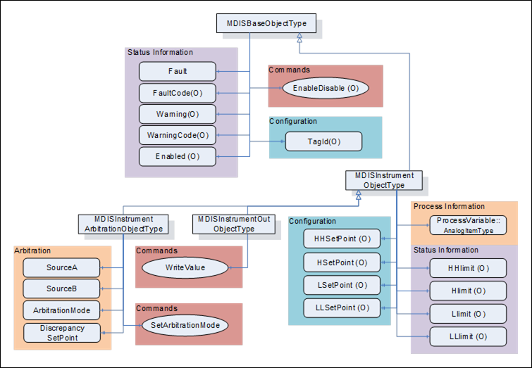
Figure 13 – MDISInstrumentObjectType & MDISInstrumentOutObjectType & MDISInstrumentArbitrationObjectType
Table 28 defines the structure of an MDISInstrumentObjectType. Any vendor specified properties that have been implemented within a project should be documented within a similar format and supplied to the DCS vendor. The addition of vendor specific properties will result in a subtype of the MDISInstrumentObjectType. If a MDISInstrumentObjectType instance is disabled, the MDISBaseObjectType defaults are followed and only the HHSetPoint, HSetPoint, LSetPoint and LLSetPoint object values will be available
Table 28 – MDISInstrumentObjectType Definition
|
Attribute |
Value |
||||
|
BrowseName |
MDISInstrumentObjectType |
||||
|
IsAbstract |
False |
||||
|
References |
Node Class |
BrowseName |
DataType |
TypeDefinition |
Other |
|
Subtype of the MDISBaseObjectType (defined in 6.1.1) |
|
||||
|
0:HasComponent |
Variable |
ProcessVariable |
0:Float |
0:AnalogItemType |
M, RO |
|
0:HasComponent |
Variable |
HHlimit |
0:Boolean |
0:BaseDataVariableType |
O, RO |
|
0:HasComponent |
Variable |
Hlimit |
0:Boolean |
0:BaseDataVariableType |
O, RO |
|
0:HasComponent |
Variable |
Llimit |
0:Boolean |
0:BaseDataVariableType |
O, RO |
|
0:HasComponent |
Variable |
LLlimit |
0:Boolean |
0:BaseDataVariableType |
O, RO |
|
0:HasProperty |
Variable |
HHSetPoint |
0:Float |
0:PropertyType |
O, RW |
|
0:HasProperty |
Variable |
HSetPoint |
0:Float |
0:PropertyType |
O, RW |
|
0:HasProperty |
Variable |
LSetPoint |
0:Float |
0:PropertyType |
O, RW |
|
0:HasProperty |
Variable |
LLSetPoint |
0:Float |
0:PropertyType |
O, RW |
|
0:HasSubtype |
ObjectType |
MDISInstrumentOutObjectType |
|
||
|
0:HasSubtype |
ObjectType |
MDISInstrumentArbitrationObjectType |
|
||
|
ConformanceUnits |
|||||
|
MDIS Instrument Base |
|||||
ProcessVariable – a Variable in engineering units that represents the value of the instance of an MDISInstrumentObjectType. It includes properties that represent the engineering units; the engineering units range and optionally the instrument range, see OPC 10000-8. The components of the MDISInstrumentObjectType Type have additional subcomponents which are defined inTable 29.
Table 29 – MDISInstrumentObjectType Type Additional Subcomponents
|
BrowsePath |
References |
NodeClass |
BrowseName |
DataType |
TypeDefinition |
Other |
|
ProcessVariable |
0:HasProperty |
Variable |
0:InstrumentRange |
0:Range |
0:PropertyType |
O |
|
ProcessVariable |
0:HasProperty |
Variable |
0:EURange |
0:Range |
0:PropertyType |
M |
|
ProcessVariable |
0:HasProperty |
Variable |
0:EngineeringUnits |
0:EUInformation |
0:PropertyType |
M |
The EUInformation DataType is defined in OPC 10000-8.
HHlimit – The instrument HH state is active
Hlimit – The instrument H state is active
Llimit – The instrument L state is active
LLlimit – The instrument LL state is active
HHSetPoint – Configuration of HHSetPoint which will set HHlimit be TRUE when the ProcessVariable value is greater than “set point value”. If this limit Variable exists on an object, but has not been configured, the HHSetPoint shall have a status code of Bad_ConfigurationError and Clients shall ignore the value. When the HHSetPoint has a Status of Bad_ConfigurationError, if the HHlimit exists, it shall have a status code of Bad_ConfigurationError and the value is ignored.
HSetPoint – Configuration of HSetPoint which will set Hlimit be TRUE when the ProcessVariable value is greater than “set point value”. If this limit Variable exists on an object, but has not been configured, the HSetPoint shall have a status code of Bad_ConfigurationError and Clients shall ignore the value. When the HSetPoint is ignored, if the Hlimit exists, it shall have a status code of Bad_ConfigurationError and the value is ignored.
LSetPoint – Configuration of LSetPoint which will set Llimit be TRUE when the ProcessVariable value is less than “set point value”. If this limit Variable exists on an object, but has not been configured, the LSetPoint shall have a status code of Bad_ConfigurationError and Clients shall ignore the value. When the LSetPoint is ignored, if the Llimit exists, it shall have a status code of Bad_ConfigurationError and the value is ignored.
LLSetPoint – Configuration of LLSetPoint which will set LLlimit be TRUE when the ProcessVariable value is less than “set point value”. If this limit Variable exists on an object, but has not been configured, the LLSetPoint shall have a status code of Bad_ConfigurationError and Clients shall ignore the value. When the LLSetPoint is ignored, if the LLlimit exists, it shall have a status code of Bad_ConfigurationError and the value is ignored.
The MDISInstrumentObjectType is a subtype of MDISBaseObjectType and inherit the FaultCode Variable. The MDISInstrumentObjectType defines the standard FaultCodes (for bits 0-15 as defined in 6.2.2) in Table 8. All subtypes of this the MDISInstrumentObjectType will inherit all FaultCodes defined in this table. Subtypes may define additional FaultCodes in their own table.
Table 30 – MDISInstrumentObjectType FaultCode Values
|
Value |
Bit no. |
Description |
|
IOFault |
0 |
Instrument has no usable value, there is an I/O fault. |
The MDISDigitalInstrumentObjectType defines the standard WarningCodes (for bits 0-15 as defined in 6.2.2) in Table 9. All subtypes of this the MDISDigitalInstrumentObjectType will inherit all WarningCodes defined in this table. Subtypes may define additional WarningCodes in their own table.
Table 31 – MDISInstrumentObjectType WarningCode Values
|
Value |
Bit No. |
Description |
|
SideAProblem |
0 |
There is an issue with the A side of this instrument [note this only applies to instrument that are arbitrated] |
|
SideBProblem |
1 |
There is an issue with the B side of this instrument [note this only applies to instrument that are arbitrated] |
|
Discrepancy |
2 |
The values differ by more than is acceptable |
|
OutOfRange |
3 |
The value of the instrument is Out of range |
Table 32 defines the structure of an MDISInstrumentOutObjectType. Any vendor specified properties that have been implemented within a project should be documented within a similar format and supplied to the DCS vendor. The addition of vendor specific properties will result in a subtype of the MDISInstrumentOutObjectType.
Table 32 – MDISInstrumentOutObjectType Definition
|
Attribute |
Value |
||||
|
BrowseName |
MDISInstrumentOutObjectType |
||||
|
IsAbstract |
False |
||||
|
References |
Node Class |
BrowseName |
DataType |
TypeDefinition |
Other |
|
Subtype of the MDISInstrumentObjectType |
|
||||
|
0:HasComponent |
Method |
WriteValue |
See 6.5.5 |
M |
|
|
ConformanceUnits |
|||||
|
MDIS Instrument Out Base |
|||||
WriteValue – This Method allows a Client to change the value of ProcessVariable on an instance of MDISInstrumentOutObjectType. The Method will return any errors that occurred on setting the value. If the Instrument is disabled, an error Bad_InvalidState shall be returned. The Client shall verify that the ProcessVariable actually changed to confirm the update.
Instrument WriteValue Method is used to change the value of the ProcessVariable in an instance of MDISInstrumentOutObjectType. The Instrument WriteValue Method operation applies to the object in the subsea system. The value of the ProcessVariable value will only update once the subsea system has provided a new value. Some systems will be able to report any errors immediately others will only be able to report that the operation was not refused. Clients are expected to monitor the ProcessVariable and ensure that the operation completed successfully. If an error occurs after the Method has returned, a Fault flag shall be set and an appropriate FaultCode will be returned. The Fault (and FaultCode) will reset on the next successful Instrument WriteValue Method invocation.
Signature:
WriteValue (
[in] 0:Float Value);
Table 33 – WriteValue Method parameters
|
Argument |
Description |
|
Value |
Float value Variable, that indicates the target state of the Variable |
Method result codes are defined as part of the Call Service (see OPC 10000-4). They are described in Table 124 for ease of reference.
Comments
The WriteValue Method will result in a change the value of the ProcessVariable Variable. The Method will report if any error occurs while writing the value of the Object. Table 34 specifies the AddressSpace representation for the WriteValue
Table 34 – WriteValue Method AddressSpace Definition
|
Attribute |
Value |
||||
|
WriteValue |
|||||
|
References |
Node Class |
DataType |
TypeDefinition |
Other |
|
|
0:HasProperty |
Variable |
0:InputArguments |
0:Argument[] |
0:PropertyType |
M |
|
ConformanceUnits |
|||||
|
MDIS Instrument Out Base |
|||||
Table 35 defines the structure of an MDISInstrumentArbitrationObjectType. Any vendor specified properties that have been implemented within a project should be documented within a similar format and supplied to the DCS vendor. The addition of vendor specific properties will result in a subtype of the MDISInstrumentArbitrationObjectType.
Table 35 – MDISInstrumentArbitrationObjectType Definition
|
Attribute |
Value |
||||
|
BrowseName |
MDISInstrumentArbitrationObjectType |
||||
|
IsAbstract |
False |
||||
|
References |
Node Class |
BrowseName |
DataType |
TypeDefinition |
Other |
|
Subtype of the MDISInstrumentObjectType |
|
||||
|
0:HasComponent |
Variable |
SourceA |
0:Float |
0:BaseDataVariableType |
M, RO |
|
0:HasComponent |
Variable |
SourceB |
0:Float |
0:BaseDataVariableType |
M, RO |
|
0:HasComponent |
Variable |
ArbitrationMode |
ArbitrationModeEnum |
0:BaseDataVariableType |
M, RO |
|
0:HasProperty |
Variable |
DiscrepancySetPoint |
0:Float |
0:PropertyType |
O, RW |
|
0:HasComponent |
Method |
SetArbitrationMode |
Defined in 6.3.7 |
O |
|
|
ConformanceUnits |
|||||
|
MDIS Instrument Arbitration Base |
|||||
The MDISInstrumentArbitrationObjectType provides for the selection between two analog sources, SourceA and SourceB. The result of the arbitration is shown in the ProcessVariable. The result can be either an average, a selection of one source as default or forcing of one source. See the ArbitrationModeEnum for a complete list of possible modes.
SourceA – a Variable in engineering units that represents the value of the first source of a MDISInstrumentArbitrationObjectType. The EngineeringUnits and Range of the ProcessVariable apply to this value.
SourceB – a Variable in engineering units that represents the value of the first source of a MDISInstrumentArbitrationObjectType. The EngineeringUnits and Range of the ProcessVariable apply to this value.
ArbitrationMode – this enumeration identifies the current arbitration mode. For the complete list of arbitration modes, see section 8.1.10. [note: the selected mode might be different than the current mode reflected in this parameter, for example in the case of a failure the current mode might indicate SourceA even if Average was selected, due to a SourceB failure]
DiscrepancySetPoint – the value represents the maximum allow difference between the SourceA and SourceB values expressed as a percentage based on the full range of the instrument. This value can only be between 0 and 100. For example, if SourceA was 10.0 and SourceB was 20.0 and the instrument range was 0 to 200, the percentage would be 5%.
The MDISInstrumentArbitrationObjectType is a subtype of MDISInstrumentObjectType and inherits the FaultCode Variable. The MDISInstrumentArbitrationObjectType defines the standard FaultCodes (for bits 0-15 as defined in 6.2.2) in Table 36 (currently empty, no additional fault codes defined). All subtypes of this the MDISInstrumentArbitrationObjectType will inherit all FaultCodes defined in this table. Subtypes may define additional FaultCodes in their own table.
Table 36 – MDISInstrumentArbitrationObjectType FaultCode Values
|
Value |
Bit no. |
Description |
|
|
|
|
The MDISInstrumentArbitrationObjectType defines the standard WarningCodes (for bits 0-15 as defined in 6.2.2) in Table 37 (currently empty, no additional warning codes defined). All subtypes of this the MDISInstrumentArbitrationObjectType will inherits all WarningCodes defined in this table. Subtypes may define additional WarningCodes in their own table.
Table 37 – MDISInstrumentArbitrationObjectType WarningCode Values
|
Value |
Bit no. |
Description |
|
|
|
|
The following section details the generic MDISChokeObjectType structure and defines the properties associated with it. This is in general a vendor and operator independent description, but all users of the MDISChokeObjectType can add vendor specific data. The vendor specific data should be defined as part of a subtype of the MDISChokeObjectType defined in this document. It is assumed that the subsea system is the Server and host of the instance of the MDISChokeObjectType. The DCS based system is the Client in the system. It is assumed that all interactions with the instance of the MDISChokeObjectType are initiated by the Client and are directed to the Server.
The MDISChokeObjectType is a basic component of any subsea control system. Subsea and surface trees have a choke valve and it is used for regulating the flow volume and with it the back pressure of liquids or gas. This document will address the hydraulic choke valve found in subsea production and water injection trees. Implementation shall ensure adherence to Mandatory [M] aspects in order to comply with the MDIS interface standardisation. Optional [O] may or may not be implemented within a project. Figure 14 provides an overview of the Choke Object as defined by MDIS. It includes all items that are defined by the MDISBaseObjectType. It illustrates that an interlock might have one or more <InterlockVariables > associated with it, or that they might not have an actual interlock associated.
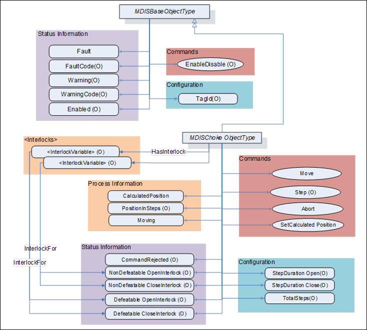
Figure 14 – MDISChokeObjectType
Table 38 defines the structure of an MDISChokeObjectType. Any vendor specified properties that have been implemented within a project should be documented within a similar format and supplied to the DCS vendor. The addition of vendor specific properties will result in a subtype of the MDISChokeObjectType. When an MDISChokeObjectType Instance is disabled the MDISBaseObjectType defaults are followed and only the StepDurationOpen, StepDurationClose and TotalSteps values will be available.
Table 38 – MDISChokeObjectType Definition
|
Attribute |
Value |
||||
|
BrowseName |
MDISChokeObjectType |
||||
|
IsAbstract |
False |
||||
|
References |
Node Class |
BrowseName |
DataType |
TypeDefinition |
Other |
|
Subtype of the MDISBaseObjectType |
|
||||
|
0:HasComponent |
Variable |
CalculatedPosition |
0:Float |
0:BaseDataVariableType |
M, RO |
|
0:HasComponent |
Variable |
SetCalculatedPositionStatus |
SetCalculatedPositionEnum |
0:BaseDataVariableType |
O, RO |
|
0:HasComponent |
Variable |
PositionInSteps |
0:Int16 |
0:BaseDataVariableType |
O, RO |
|
0:HasComponent |
Variable |
Moving |
ChokeMoveEnum |
0:BaseDataVariableType |
M, RO |
|
0:HasComponent |
Variable |
CommandRejected |
0:Boolean |
0:BaseDataVariableType |
O, RO |
|
0:HasComponent |
Method |
Move |
See 6.6.4 |
M |
|
|
0:HasComponent |
Method |
Step |
See 6.6.5 |
O |
|
|
0:HasComponent |
Method |
Abort |
See 6.6.6 |
M |
|
|
0:HasComponent |
Method |
SetCalculatedPosition |
See 6.6.7 |
M |
|
|
0:HasComponent |
Variable |
NonDefeatableOpenInterlock |
0:Boolean |
0:BaseDataVariableType |
O, RO |
|
0:HasComponent |
Variable |
DefeatableOpenInterlock |
0:Boolean |
0:BaseDataVariableType |
O, RO |
|
0:HasComponent |
Variable |
NonDefeatableCloseInterlock |
0:Boolean |
0:BaseDataVariableType |
O, RO |
|
0:HasComponent |
Variable |
DefeatableCloseInterlock |
0:Boolean |
0:BaseDataVariableType |
O, RO |
|
0:HasProperty |
Variable |
StepDurationOpen |
0:Duration |
0:PropertyType |
O, RO |
|
0:HasProperty |
Variable |
StepDurationClose |
0:Duration |
0:PropertyType |
O, RO |
|
0:HasProperty |
Variable |
TotalSteps |
0:UInt16 |
0:PropertyType |
O, RO |
|
HasInterlock |
Variable |
<InterlockPlaceholder> |
0:Boolean |
InterlockVariableType |
OP |
|
ConformanceUnits |
|||||
|
MDIS Choke Base |
|||||
CalculatedPosition – A floating point number that represents the estimated percent open of the choke. This value can be updated using the SetCalculatedPosition Method.
SetCalculatedPositionStatus – an enumeration that reflect the status of a SetCalculatedPosition Command. This variable is present if the SetCalculatedPosition command can return asynchronously.
PositionInSteps – An Int16 that represents position in steps for the choke.
CommandRejected –– A flag that, if set to True, indicates that the choke has rejected the last command issued to it. The command could be rejected for a number of reasons. Possible reasons for rejecting a command include:
- Loss of subsea communication reported by the SPCS.
- An active interlock.
- The choke is in the disabled state
Enabled – This Boolean reflects if the choke is available for control. The behaviour follows the MDISBaseObjectType.
Moving – An enumeration indicating the confirmed operation of the choke, (confirmed by SPCS Vendor). Possible status for a choke is moving and stopped.
Move – This Method allows an operator to increase or decrease the size of the opening in the choke. This command moves the choke to the percent value provided as part of the command.
Step – This Method allows an operator to increase or decrease the size of the opening in the choke. This command moves the choke the number of steps provided as part of the command.
Abort – This Method allows an operator to cancel any currently active move or step command.
SetCalculatedPosition – This Method is used to calibrate the CalculatedPosition. It can only be called when the choke is not moving.
EnableDisable – The choke, when disabled, places a non-defeatable interlock set on Move and Step functionality, in addition to the functionality described in the MDISBaseObjectType.
StepDurationOpen – SPCS open step duration period. This is the time in milliseconds for the choke to open one step.
StepDurationClose – SPCS close step duration period. This is the time in milliseconds for the choke to close one step.
TotalSteps – Total number of steps is the max steps of a choke.
<InterlockPlaceholder > – The number of interlock Variables will change based on the project and even choke instance. The Variables shall be of InterlockVariableType or a subtype of it. They will be referenced by a HasInterlock Reference and will contain an InterlockFor Reference. Clients can use this information to categorise the interlocks appropriately.
The following Variables indicate that an interlock is set (TRUE) or is not set (FALSE). The Variable shall be the target of an InterlockFor Reference from an instance of an InterlockVariableType that describes the actual interlock.
NonDefeatableOpenInterlock – The open choke command is interlocked and cannot be overridden.
DefeatableOpenInterlock – The open choke command is interlocked and can be overridden.
NonDefeatableCloseInterlock – The close choke command is interlocked and cannot be overridden.
DefeatableCloseInterlock – The close choke command is interlocked and can be overridden.
The MDISChokeObjectType is a subtype of MDISBaseObjectType and inherit the FaultCode Variable. The MDISChokeObjectType defines the standard FaultCodes (for bits 0-15 as defined in 6.2.2) in Table 39. All subtypes of this the MDISChokeObjectType will inherit all FaultCodes defined in this table. Subtypes may define additional FaultCodes in their own table.
Table 39 – MDISChokeObjectType FaultCode Values
|
Value |
Bit no. |
Description |
|
FailedToMove |
0 |
The Choke failed to move in response to a command. |
|
CommunicationFault |
1 |
Not possible to operate the choke. |
The MDISChokeObjectType defines the standard WarningCodes (for bits 0-15 as defined in 6.2.2)in Table 40. All subtypes of this the MDISChokeObjectType will inherit all WarningCodes defined in this table. Subtypes may define additional WarningCodes in their own table.
Table 40 – MDISChokeObjectType WarningCode Values
|
Value |
Bit no. |
Description |
|
SideAProblem |
0 |
There is an issue with the A side of the choke. |
|
SideBProblem |
1 |
There is an issue with the B side of the choke. |
|
Discrepancy |
2 |
There is a discrepancy between the calculated position and the measured position. |
|
UncommandedChange |
3 |
The choke position changed without a command. |
Move Method is used to adjust the opening size in a choke.
Signature:
Move (
[in] 0:Float Position,
[in] 0:BooleanOverrideInterlocks,
[in] SEMEnum SEM);
Table 41 – Move Method Arguments( Choke)
|
Argument |
Description |
|
Position |
A number (in percent) indicating the percent open to be moved to when operated. |
|
OverrideInterlocks |
Boolean indicating if the open or close command should override any defeatable interlocks |
|
SEM |
The selection of which SEM to send the command to. |
Method result codes are defined as part of the Call Service (see OPC 10000-4). They are described in Table 124 for ease of reference.
Comments:
The Move Method initiates a move command. Parameters include the position value in percent, overriding of any interlocks and the SEM selection to use for the command. The Position Method argument value shall be between 0 and 100. The server shall return Bad_OutOfRange if the Position Method argument value is outside of this range. After receiving the new commanded position, the choke will start to move. The Method will complete when the command has been accepted. The move operation may or may not have completed when the Method returns. The Method returns errors only if the operation cannot be started. The Client must monitor the Moving Variable to determine when the move operation actually finishes.
If a Server does not support an Override of defeatable interlocks, then this parameter will be ignored by the Server. If any interlocks are active the appropriate error code is returned.
If a Server does not support the selection of SEM, this parameter is ignored.
Table 42 specifies the AddressSpace representation for the choke Move Method.
Table 42 – Move Method AddressSpace Definition (Choke)
|
Attribute |
Value |
||||
|
BrowseName |
Move |
||||
|
References |
Node Class |
BrowseName |
DataType |
TypeDefinition |
Other |
|
0:HasProperty |
Variable |
0:InputArguments |
0:Argument[] |
0:PropertyType |
M |
|
ConformanceUnits |
|||||
|
MDIS Choke Base |
|||||
|
MDIS Electric Choke Base |
|||||
Choke Step Method is used to adjust the opening size in a choke.
Signature
Step (
[in] ChokeCommandEnum Direction,
[in] 0:UInt16 Steps,
[in] 0:Boolean OverrideInterlocks,
[in] SEMEnum SEM);
Table 43 – Step Method Arguments (Choke)
|
Argument |
Description |
|
Direction |
Enumeration to indicate if an open request or close request is being initiated |
|
Steps |
The number of steps to either open or close the choke |
|
OverrideInterlocks |
Boolean indicating if the open or close command should override any defeatable interlocks |
|
SEM |
The selection of which SEM to send the command to. |
Method result codes are defined as part of the Call Service (see OPC 10000-4). They are described in Table 124 for ease of reference.
Comments
The choke Step Method initiates a move command. Parameters include the direction (open or close), the number of steps to step, overriding of any interlocks and the SEM selection to use for the command. After receiving the command, the choke will start to move. The Method will complete when the command has been accepted. The move operation may or may not have completed when the Method returns. The Method returns errors only if the operation cannot be started. The Client must monitor the Moving Variable to determine when the Step command actually finishes.
If a Server does not support an override of defeatable interlocks, then the OverrideInterlocks parameter will be ignored by the Server and if any interlocks are active the appropriate error code is returned.
If a Server does not support the selection of SEM, the SEM parameter is ignored.
Table 44 specifies the AddressSpace representation for the Choke Step Method.
Table 44 – Step Method AddressSpace Definition (Choke)
|
Attribute |
Value |
||||
|
Step |
|||||
|
References |
Node Class |
DataType |
TypeDefinition |
Othrer |
|
|
0:HasProperty |
Variable |
0:InputArguments |
0:Argument[] |
0:PropertyType |
M |
|
ConformanceUnits |
|||||
|
MDIS Choke Step Method |
|||||
Choke Abort Method is used to cancel any active move command in the Choke.
Signature:
Abort ();
Method result codes are defined as part of the Call Service (see OPC 10000-4). They are described in Table 124 for ease of reference.
Comments
The choke Abort Method will try to cancel any active choke Move or Step commands. If no Move or Step command is in progress, the command will be ignored and return successful. The Method will complete when the command has been accepted. The abort operation may or may not have completed when the Method returns. The Method returns errors only if the operation cannot be started. The Client shall monitor the Moving and if provided the CommandRejected Variables to determine if the abort was successful or failed. Table 45 specifies the AddressSpace representation for the choke Abort Method.
Table 45 – Abort Method AddressSpace Definition (Choke)
|
Attribute |
Value |
|||||
|
BrowseName |
Abort |
|||||
|
References |
Node Class |
BrowseName |
DataType |
TypeDefinition |
Other |
|
|
|
|
|
|
|
|
|
|
ConformanceUnits |
||||||
|
MDIS Choke Base |
||||||
SetCalculatedPosition Method is used to synchronise the CalculatedPosition to the actual choke position.
Signature:
SetCalculatedPosition (
[in] 0:Float Position);
Table 46 – SetCalculatedPosition Method Arguments (Choke)
|
Argument |
Description |
|
Position |
A number (in percent) |
Method result codes are defined as part of the Call Service (see OPC 10000-4). They are described in Table 124 for ease of reference.
Comments:
The SetCalculatedPosition Method is used to set the CalculatedPosition. It can only be called when the choke is not moving. The parameter is the calculated position. This method may return when the CalculatedPosition has been updated or it may return a status of Completes_Asynchronously. If it returns Completes_Asynchronously the Client will have to monitor the SetCalculatedPositionStatus to determine if an error occurred or the command completed. The SetCalculatedPositionStatus will reset on the next successful SetCalculatedPosition Method invocation.
Table 47 specifies the AddressSpace representation for the SetCalculatedPosition Method.
Table 47 – SetCalculatedPosition Method AddressSpace Definition (Choke)
|
Attribute |
Value |
|||||
|
BrowseName |
SetCalculatedPosition |
|||||
|
References |
Node Class |
BrowseName |
DataType |
TypeDefinition |
Other |
|
|
0:HasProperty |
Variable |
0:InputArguments |
0:Argument[] |
0:PropertyType |
M |
|
|
ConformanceUnits |
||||||
|
MDIS Choke Base |
||||||
The following section details the generic MDISElectricChokeObjectType structure and defines the properties associated with it. This is in general a vendor and operator independent description, but all users of the MDISElectricChokeObjectType can add vendor specific data. The vendor specific data should be defined as part of a subtype of the MDISElectricChokeObjectType defined in this document. It is assumed that the subsea system is the Server and host of the instance of the MDISElectricChokeObjectType. The DCS based system is the Client in the system. It is assumed that all interactions with the instance of the MDISElectricChokeObjectType are initiated by the Client and are directed to the Server.
The MDISElectricChokeObjectType is a basic component of any subsea control system. Subsea and surface trees have a choke valve and it is used for regulating the flow volume and with it the back pressure of liquids or gas. This document will address the electric choke valve found in subsea production and water injection trees. Implementation shall ensure adherence to Mandatory [M] aspects in order to comply with the MDIS interface standardisation. Optional [O] may or may not be implemented within a project. Figure 14 provides an overview of the Choke Object as defined by MDIS. It includes all items that are defined by the MDISBaseObjectType. It illustrates that an interlock might have one or more Interlock variables associated with it, or that they might not have an actual interlock associated.

Figure 15 – MDISElectricChokeObjectType
Table 38 defines the structure of an MDISElectricChokeObjectType. Any vendor specified properties that have been implemented within a project should be documented within a similar format and supplied to the DCS vendor. The addition of vendor specific properties will result in a subtype of the MDISElectricChokeObjectType. When an MDISElectricChokeObjectType Instance is disabled the MDISBaseObjectType defaults are followed.
Table 48 – MDISElectricChokeObjectType Definition
|
Attribute |
Value |
||||
|
BrowseName |
MDISElectricChokeObjectType |
||||
|
IsAbstract |
False |
||||
|
References |
Node Class |
BrowseName |
DataType |
TypeDefinition |
Other |
|
Subtype of the MDISBaseObjectType |
|
||||
|
0:HasComponent |
Variable |
ActualPosition |
0:Float |
0:BaseDataVariableType |
M, RO |
|
0:HasComponent |
Variable |
Moving |
ChokeMoveEnum |
0:BaseDataVariableType |
M, RO |
|
0:HasComponent |
Variable |
CommandRejected |
0:Boolean |
0:BaseDataVariableType |
O, RO |
|
0:HasComponent |
Method |
Move |
See 6.6.4 |
M |
|
|
0:HasComponent |
Method |
Abort |
See 6.6.6 |
M |
|
|
0:HasComponent |
Variable |
NonDefeatableOpenInterlock |
0:Boolean |
0:BaseDataVariableType |
O, RO |
|
0:HasComponent |
Variable |
DefeatableOpenInterlock |
0:Boolean |
0:BaseDataVariableType |
O, RO |
|
0:HasComponent |
Variable |
NonDefeatableCloseInterlock |
0:Boolean |
0:BaseDataVariableType |
O, RO |
|
0:HasComponent |
Variable |
DefeatableCloseInterlock |
0:Boolean |
0:BaseDataVariableType |
O, RO |
|
HasInterlock |
Variable |
<InterlockPlaceholder> |
0:Boolean |
InterlockVariableType |
OP |
|
ConformanceUnits |
|||||
|
MDIS Electric Choke Base |
|||||
ActualPosition – A floating point number that represents the percent open of the choke.
CommandRejected – A flag that, if set to True, indicates that the choke has rejected the last command issued to it. The command could be rejected for a number of reasons. Possible reasons for rejecting a command include:
- Loss of subsea communication reported by the SPCS.
- An active interlock.
- The choke is in the disabled state
Enabled – This Boolean reflects if the choke is available for control. The behaviour follows the MDISBaseObjectType.
Moving – An enumeration indicating the confirmed operation of the choke, (confirmed by SPCS Vendor). Possible status for a choke is moving and stopped.
Move – This Method allows an operator to increase or decrease the size of the opening in the choke. This command moves the choke to the percent value provided as part of the command.
Abort – This Method allows an operator to cancel any currently active move command.
EnableDisable – The choke, when disabled, places a non-defeatable interlock set on Move functionality, in addition to the functionality described in the MDISBaseObjectType.
<InterlockPlaceholder > – The number of interlock Variables will change based on the project and even choke instance. The Variables shall be of InterlockVariableType or a subtype of it. They will be referenced by a HasInterlock Reference and will contain an InterlockFor Reference. Clients can use this information to categorise the interlocks appropriately.
The following Variables indicate that an interlock is set (TRUE) or is not set (FALSE). The Variable shall be the target of an InterlockFor Reference from an instance of an InterlockVariableType that describes the actual interlock.
NonDefeatableOpenInterlock – The open choke command is interlocked and cannot be overridden.
DefeatableOpenInterlock – The open choke command is interlocked and can be overridden.
NonDefeatableCloseInterlock – The close choke command is interlocked and cannot be overridden.
DefeatableCloseInterlock – The close choke command is interlocked and can be overridden.
The MDISElectricChokeObjectType is a subtype of MDISBaseObjectType and inherit the FaultCode Variable. The MDISElectricChokeObjectType defines the standard FaultCodes (for bits 0-15 as defined in 6.2.2) in Table 49. All subtypes of this the MDISElectricChokeObjectType will inherit all FaultCodes defined in this table. Subtypes may define additional FaultCodes in their own table.
Table 49 – MDISElectricChokeObjectType FaultCode Values
|
Value |
Bit no. |
Description |
|
FailedToMove |
0 |
The Choke failed to move in response to a command. |
|
CommunicationFault |
1 |
Not possible to operate the choke. |
The MDISElectricChokeObjectType defines the standard WarningCodes (for bits 0-15 as defined in 6.2.2) in Table 50. All subtypes of this the MDISElectricChokeObjectType will inherit all WarningCodes defined in this table. Subtypes may define additional WarningCodes in their own table.
Table 50 – MDISElectricChokeObjectType WarningCode Values
|
Value |
Bit no. |
Description |
|
SideAProblem |
0 |
There is an issue with the A side of the choke. |
|
SideBProblem |
1 |
There is an issue with the B side of the choke. |
|
UncommandedChange |
3 |
The choke position changed without a command. |
|
CalibrationRequired |
4 |
The choke requires calibration |
The following section details the generic MDISValveObjectType structure and defines the properties associated with it. This is in general a vendor and operator independent description, but all users of this MDISValveObjectType can add vendor specific data. The vendor specific data should be defined as part of a subtype of the MDISValveObjectType defined in this document. It is required that the subsea system is the Server and host of the valve Object. The DCS based system is the Client in the system. It is required that all interaction with the valve Object is initiated by the Client and is directed to the Server.
The valve Object is a basic component of any subsea control system. Subsea and surface trees have a large variety of valve configurations and combinations of manual and / or actuated (hydraulic or pneumatic) valves. Implementation shall ensure adherence to Mandatory [M] aspects in order to comply with the MDIS interface standardisation. Optional [O] may or may not be implemented within a project. Figure 16 provides an overview of the MDISValveObjectType as defined by MDIS. The figure includes all items inherited from the MDISBaseObjectType. It illustrates that an interlock might have one or more Interlock variables associated with it, or that they might not have an actual interlock associated.
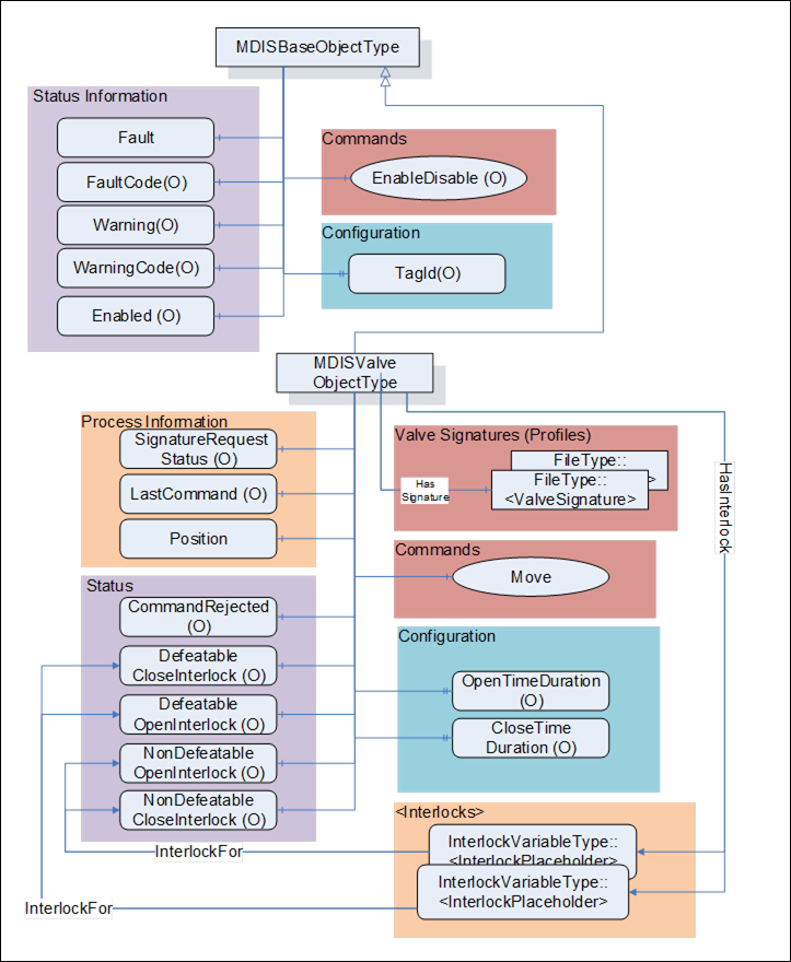
Figure 16 – Valve Object Overview
Table 51 details the generic properties for the MDISValveObjectType. Any vendor specified properties that have been implemented within a project should be documented within a similar format and supplied to the DCS vendor. The addition of vendor specific properties will result in a subtype of the MDISValveObjectType. When an MDISValveObjectType Instance is disabled the MDISBaseObjectType defaults are followed and only the OpenTimeDuration and CloseTimeDuration values will be available.
Table 51 – MDISValveObjectType Definition
|
Attribute |
Value |
||||
|
BrowseName |
MDISValveObjectType |
||||
|
IsAbstract |
False |
||||
|
References |
Node Class |
BrowseName |
DataType |
TypeDefinition |
Other |
|
Subtype of the MDISBaseObjectType |
|
||||
|
0:HasComponent |
Variable |
Position |
ValvePositionEnum |
0:BaseDataVariableType |
M, R |
|
0:HasComponent |
Variable |
CommandRejected |
0:Boolean |
0:BaseDataVariableType |
O, RO |
|
0:HasComponent |
Variable |
SignatureRequestStatus |
SignatureStatusEnum |
0:BaseDataVariableType |
O, RO |
|
0:HasComponent |
Variable |
LastCommand |
CommandEnum |
0:BaseDataVariableType |
O, RO |
|
0:HasComponent |
Variable |
NonDefeatableOpenInterlock |
0:Boolean |
0:BaseDataVariableType |
O, RO |
|
0:HasComponent |
Variable |
DefeatableOpenInterlock |
0:Boolean |
0:BaseDataVariableType |
O, RO |
|
0:HasComponent |
Variable |
NonDefeatableCloseInterlock |
0:Boolean |
0:BaseDataVariableType |
O, RO |
|
0:HasComponent |
Variable |
DefeatableCloseInterlock |
0:Boolean |
0:BaseDataVariableType |
O, RO |
|
0:HasComponent |
Method |
Move |
See 6.8.4 |
M |
|
|
HasInterlock |
Variable |
<InterlockPlaceholder> |
0:Boolean |
InterlockVariableType |
OP, RO |
|
0:HasProperty |
Variable |
OpenTimeDuration |
0:Duration |
0:PropertyType |
O, RO |
|
0:HasProperty |
Variable |
CloseTimeDuration |
0:Duration |
0:PropertyType |
O, RO |
|
HasSignature |
Object |
<ValveSignature> |
|
FileType |
OP |
|
ConformanceUnits |
|||||
|
MDIS Valve Base |
|||||
The following items describe status information from the valve:
- SignatureRequestStatus – The collection of data required for a valve signature may take some time after the completion of a Move command. The SignatureRequestStatus Variable indicates the status of the current signature request (see 8.1.4 for a description of the possible enumerations).
- LastCommand – The enumeration reflects the last command sent to the equipment by the SPCS (see 8.1.5 for a description of the possible enumerations).
- Enabled – This Boolean reflects if the valve is available for control. The behaviour follows the MDISBaseObjectType.
- Position – This enumeration provides information about the current position of the valve (see section 8.1.7 for additional details).
- CommandRejected – A flag that, if set to True, indicates that the valve has rejected the last command issued to it. The command could be rejected for a number of reasons. Possible reasons for rejecting a command include:
- Loss of subsea communication reported by the SPCS.
- An active interlock.
- The valve is in the disabled state.
For any of the following Variables, if they are true, there shall be at least one instance of an InterlockVariableType that describes the active interlock.
- NonDefeatableOpenInterlock – The open valve command is interlocked and cannot be overridden.
- DefeatableOpenInterlock – The open valve command is interlocked and can be overridden.
- NonDefeatableCloseInterlock – The close valve command is interlocked and cannot be overridden.
- DefeatableCloseInterlock – The close valve command is interlocked and can be overridden.
The following items are related to valve control: These items allow information to flow from the DCS to the SPCS. All commands from the DCS to SPCS may require access controls to ensure that only appropriate personnel initiate them.
<InterlockPlaceholder> – The number of interlock Variables will change based on the project and even valve instance. The Variables shall be of InterlockVariableType or a subtype of it. The interlock contains an InterlockFor Reference to one of the previously described flags. Clients can use this information to categorise the interlocks appropriately. Figure 17 provides an example of how this interlock Variable is used and could be deployed.
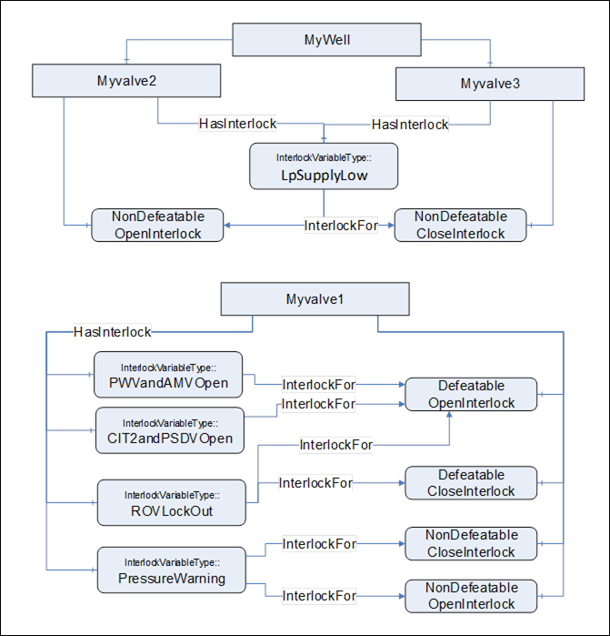
Note: in OPC UA it is allowed to have a Node which is the target of multiple 0:HasComponent References, this allows a single interlock to be shared between multiple Objects; such as a low pressure interlock that maybe shared by all of the valves and chokes in a system.
The following items describe configuration related items:
- OpenTimeDuration – Estimated max time to travel to open position, used for DCS systems to indicate a move fail condition if time is exceeded. Time is provided in milliseconds. The OpenTimeDuration can be used for any kind of valve (hydraulic, electric, etc.). [Note: this time is an estimate and Clients may need to allow for additional delays in transmitting and receiving any move commands].
- CloseTimeDuration - Estimated max time to travel to close position, used for DCS systems to indicate a move fail condition if time is exceeded. Time is provided in milliseconds. The CloseTimeDuration can be used for any kind of valve (hydraulic, electric, etc.) [Note: this time is an estimate and Clients may need to allow for additional delays in transmitting and receiving any Move commands].
- <ValveSignature> - The reference shall point to an instance of FileType, where the file contains valve signature information. The name of this object is project or vendor specific, but it should be related to the name of the instance of the MDISValveObjectType. The name shall include a timestamp. The FileType ObjectType (defined in OPC 10000-5 (older version), OPC 10000-20 (newer versions)) includes two properties (illustrated below), for all MDIS instances both of these properties shall have the value False. For additional detail see 6.14.3.
|
0:HasProperty |
Variable |
0:Writable |
0:Boolean |
0:PropertyType |
Mandatory |
|
0:HasProperty |
Variable |
0:UserWritable |
0:Boolean |
0:PropertyType |
Mandatory |
Vendor specific subtypes of this ObjectType are allowed. They may add additional vendor specific information or may change some Optional items to Mandatory. A standard file content is defined in Annex E.
The MDISValveObjectType is a subtype of MDISBaseObjectType and inherit the FaultCode Variable. The MDISValveObjectType defines the standard FaultCodes (for bits 0-15 as defined in 6.2.2) in Table 52. All subtypes of this the MDISValveObjectType will inherit all FaultCodes defined in this table. Subtypes may define additional FaultCodes in their own table.
Table 52 – MDISValveObjectType FaultCode Values
|
Value |
Bit no. |
Description |
|
CommunicationFault |
1 |
Not possible to operate the valve. |
|
FailedToOpen |
2 |
Device failed to move open |
|
FailedToClose |
3 |
Device failed to move close |
|
PressureFeedbackFailure |
4 |
Pressure check feedback verification failed |
|
FlowFeedbackFailure |
5 |
Flow check feedback verification failed |
The MDISValveObjectType defines the standard WarningCodes (for bits 0-15 as defined in 6.2.2) in Table 53. All subtypes of this the MDISValveObjectType will inherit all WarningCodes defined in this table. Subtypes may define additional WarningCodes in their own table.
Table 53 – MDISValveObjectType WarningCode Values
|
Value |
Bit no. |
Description |
|
SideAProblem |
0 |
There is an issue with the A side of the valve |
|
SideBProblem |
1 |
There is an issue with the B side of the valve. |
|
PositionDiscrepancy |
2 |
The valve position has a discrepancy (Side A and Side B are different and neither is broken) |
|
UncommandedChange |
3 |
Position of valve changed without an authorized move |
|
CalibrationRequired |
4 |
The valve requires calibration |
Move Method is used to open or close a valve.
Signature
Move (
[in] CommandEnum Direction,
[in] 0:Boolean OverrideInterlock,
[in] SEMEnum SEM,
[in] 0:Boolean Signature,
[in] 0:Boolean ShutdownRequest);
Table 54 – Move Arguments (Valve)
|
Argument |
Description |
|
Direction |
The enumeration indicates whether the command is to open the valve or to close the valve |
|
OverrideInterlock |
Boolean indicating if the open or close command should override any defeatable interlocks |
|
SEM |
The enumeration indicates which SEM to send the command to. |
|
Signature |
Boolean indicating if a profile /signature should be generated by this move command request. If the optional Variable SignatureRequestStatus is not provided on the Object, this parameter is ignored by the Server. |
|
ShutdownRequest |
Boolean indicates that this command is part of a shutdown sequence. It should be noted that the responsibility for the shutdown is on the DCS and operator side. All non defeatable interlocks of the subsea system will be overridden which can cause damage to the subsea system. |
Method result codes are defined as part of the Call Service (see OPC 10000-4). They are described in Table 124 for ease of reference.
Comments:
The Move Method initiates a move operation. Parameters include opening or closing of the valve, overriding of any interlocks, the SEM selection to use for the command, if a profile / signature is being requested for this move operation or if a shutdown is being requested. The Method will complete when the command has been accepted. If the command has not been accepted by the Server, then the Method returns an error indicating the operation could not be performed. In the case when the Move command is accepted by the Server, the move operation may or may not be complete at the time the Method returns to the Client. Therefore, the Client must monitor the Position of the valve to determine when the Move command actually finishes.
The OverrideInterlocks, SEM, Signature and Shutdown are optional parameters, but OPC UA Methods do not allow for optional parameters. These parameters must always be provided. On a Server basis the parameter may be configured to not be utilised. If a Server is configured to not utilise a parameter, this is because the functionality is not required.
Table 55 specifies the AddressSpace representation for the Move Method.
Table 55 – Move Method AddressSpace Definition (Valve)
|
Attribute |
Value |
||||
|
BrowseName |
Move |
||||
|
References |
Node Class |
BrowseName |
DataType |
TypeDefinition |
Other |
|
0:HasProperty |
0:InputArguments |
0:Argument[] |
0:PropertyType |
M |
|
|
ConformanceUnits |
|||||
|
MDIS Valve Base |
|||||
The following section details the generic MDISCIMVObjectType and defines the properties associated with it. This is in general a vendor and operator independent description, but all users of the MDISCIMVObjectType can add vendor specific data. The vendor specific data should be defined as part of a subtype of the MDISCIMVObjectType defined in this document. It is assumed that the subsea system is the Server and host of the instance of the MDISCIMVObjectType. The DCS based system is the Client in the system. It is assumed that all interactions with the instance of the MDISCIMVObjectType are initiated by the Client and are directed to the Server.
The Chemical Injection Metering Valve (CIMV) is a basic component of any subsea control system. CIMVs regulate the flow of a chemical delivered to subsea production system. This document will address the CIMV found in subsea production trees. Implementation shall ensure adherence to Mandatory [M] aspects in order to comply with the MDIS interface standardisation. Optional [O] may or may not be implemented within a project. Figure 18 provides an overview of the CIMV Object as defined by MDIS and the MDISCIMVObjectType. It includes all items that are defined by the MDISBaseObjectType.
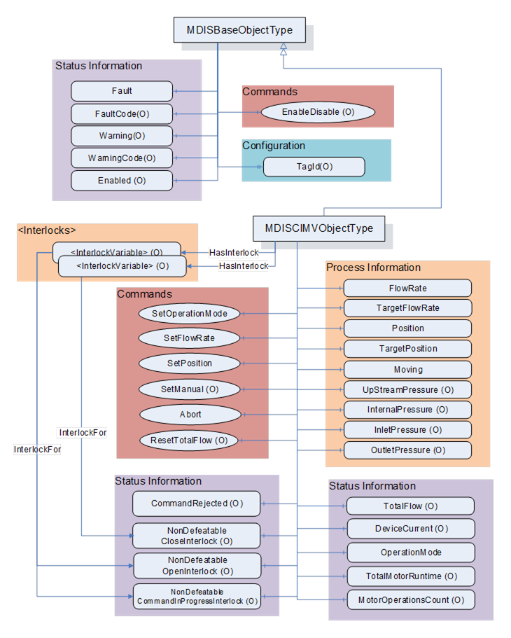
Figure 18 – MDISCIMVObjectType Overview
Table 56 defines the structure of an MDISCIMVObjectType. Any vendor specified Properties that have been implemented within a project should be documented within a similar format and supplied to the DCS vendor. The addition of vendor specific properties will result in a subtype of the MDISCIMVObjectType. When an MDISCIMVObjectType Instance is disabled the MDISBaseObjectType defaults are followed - no additional values will be available.
Table 56 – MDISCIMVObjectType Definition
|
Attribute |
Value |
||||
|
BrowseName |
MDISCIMVObjectType |
||||
|
IsAbstract |
False |
||||
|
References |
Node Class |
BrowseName |
DataType |
TypeDefinition |
Other |
|
Subtype of the MDISBaseObjectType (define in 6.2.2) |
|
||||
|
0:HasComponent |
Variable |
OperationMode |
CIMVOperationModeEnum |
0:BaseDataVariableType |
M, RO |
|
0:HasComponent |
Variable |
FlowRate |
0:Float |
0:AnalogItemType |
M, RO |
|
0:HasComponent |
Variable |
TargetFlowRate |
0:Float |
0:AnalogItemType |
M, RO |
|
0:HasComponent |
Variable |
TotalFlow |
0:Float |
0:AnalogItemType |
O, RO |
|
0:HasComponent |
Method |
ResetTotalFlow |
See 6.9.9 |
O |
|
|
0:HasComponent |
Variable |
Position |
0:Float |
0:BaseDataVariableType |
M, RO |
|
0:HasComponent |
Variable |
TargetPosition |
0:Float |
0:BaseDataVariableType |
M, RO |
|
0:HasComponent |
Variable |
Moving |
CIMVMoveEnum |
0:BaseDataVariableType |
M, RO |
|
0:HasComponent |
Object |
TotalMotorRuntime |
|
MDISCounterObjectType |
O, RO |
|
0:HasComponent |
Object |
MotorOperationsCount |
|
MDISCounterObjectType |
O, RO |
|
0:HasComponent |
Variable |
DeviceCurrent |
0:Float |
0:AnalogItemType |
O, RO |
|
0:HasComponent |
Variable |
InletPressure |
0:Float |
0:AnalogItemType |
O, RO |
|
0:HasComponent |
Variable |
InternalPressure |
0:Float |
0:AnalogItemType |
O, RO |
|
0:HasComponent |
Variable |
OutletPressure |
0:Float |
0:AnalogItemType |
O, RO |
|
0:HasComponent |
Variable |
CommandRejected |
0:Boolean |
0:BaseDataVariableType |
O, RO |
|
0:HasComponent |
Method |
SetOperationMode |
See 6.9.4 |
M |
|
|
0:HasComponent |
Method |
SetFlowRate |
See 6.9.5 |
M |
|
|
0:HasComponent |
Method |
SetPosition |
See 6.9.6 |
M |
|
|
0:HasComponent |
Method |
SetManual |
See 6.9.7 |
O |
|
|
0:HasComponent |
Method |
Abort |
See 6.9.8 |
M |
|
|
0:HasComponent |
Variable |
NonDefeatableOpenInterlock |
0:Boolean |
0:BaseDataVariableType |
O, RO |
|
0:HasComponent |
Variable |
NonDefeatableCloseInterlock |
0:Boolean |
0:BaseDataVariableType |
O, RO |
|
0:HasComponent |
Variable |
NonDefeatableCommandInProgressInterlock |
0:Boolean |
0:BaseDataVariableType |
O, RO |
|
HasInterlock |
Variable |
<InterlockPlaceholder> |
0:Boolean |
InterlockVariableType |
OP, RO |
|
ConformanceUnits |
|||||
|
MDIS CIMV Base |
|||||
The components of the MDISCIMVObjectType have additional references which are defined in Table 57.
Table 57 – MDISCIMVObjectType Additional Subcomponents
|
Source Path |
References |
NodeClass |
BrowseName |
DataType |
TypeDefinition |
Other |
|
TotalMotorRuntime |
0:HasComponent |
Variable |
Count |
0:Duration |
0:BaseDataVariableType |
M |
|
TotalMotorRuntime |
0:HasComponent |
Method |
SetCount |
|
|
M |
|
MotorOperationsCount |
0:HasComponent |
Variable |
Count |
0:UInt32 |
0:BaseDataVariableType |
M |
|
MotorOperationsCount |
0:HasComponent |
Method |
SetCount |
|
|
M |
|
FlowRate |
0:HasProperty |
Variable |
0:EngineeringUnits |
0:EUInformation |
0:PropertyType |
M |
|
TargetFlowRate |
0:HasProperty |
Variable |
0:EngineeringUnits |
0:EUInformation |
0:PropertyType |
M |
|
TotalFlow |
0:HasProperty |
Variable |
0:EngineeringUnits |
0:EUInformation |
0:PropertyType |
M |
|
DeviceCurrent |
0:HasProperty |
Variable |
0:EngineeringUnits |
0:EUInformation |
0:PropertyType |
M |
|
InletPressure |
0:HasProperty |
Variable |
0:EngineeringUnits |
0:EUInformation |
0:PropertyType |
M |
|
InternalPressure |
0:HasProperty |
Variable |
0:EngineeringUnits |
0:EUInformation |
0:PropertyType |
M |
|
OutletPressure |
0:HasProperty |
Variable |
0:EngineeringUnits |
0:EUInformation |
0:PropertyType |
M |
OperationMode – An enumeration that reflects the current operating mode of the CIMV (see 8.1.8 for a description of the possible enumerations).
FlowRate – A float value that indicates the current inhibitor flow rate. It includes properties that represent the engineering units, the engineering units range and optionally the instrument range. Refer to table 16 for illustration.
TargetFlowRate – A float value that indicates the flow rate which the CIMV will automatically try to maintain when the OperationMode is set to “Flow” (refer to 8.1.8). It includes properties that represent the engineering units, the engineering units range and optionally the instrument range. Refer to table 16 for illustration. The SetFlowRate method (refer to 6.9.5) can be used to change this value.
TotalFlow – A float value that indicates the accumulated volume of inhibitor which has been injected since it was last reset. It includes properties that represent the engineering units, the engineering units range and optionally the instrument range. Refer to table 16 for illustration. If the TotalFlow is provided then the ResetTotalFlow Method shall also be provided.
Position – A Float that represents the current position in percent open for the CIMV.
TargetPosition – A Float that represents the position in percent open which the CIMV will automatically try to maintain when the OperationMode is set to “Position” (refer to 8.1.8). The SetPosition method (refer to 6.9.6) can be used to change this value.
Moving – An enumeration indicating the confirmed operation of the CIMV (confirmed by SPCS Vendor). (see 8.1.9 for a description of the possible enumerations)
TotalMotorRuntime – A value that indicates the accumulated duration of time that the motor has run since it was put into service. The object includes a reset method (see 6.10).
MotorOperationsCount – A value that indicates the total number of motor operations that have been completed since it was last reset. The object includes a reset method (see 6.10).
DeviceCurrent – The measure of the Electrical current being consumed by the device (e.g., motor operations). It includes properties that represent the engineering units, the engineering units range and optionally the instrument range. Refer to table 16 for illustration.
InletPressure – Current pressure on the upstream side of the throttling valve. Upstream in this case means closer to the source of the inhibitor chemical than the throttling valve. It includes properties that represent the engineering units, the engineering units range and optionally the instrument range. Refer to table 16 for illustration.
InternalPressure – Current pressure at the stem of the throttling valve. It includes properties that represent the engineering units, the engineering units range and optionally the instrument range. Refer to table 16 for illustration.
OutletPressure – Current pressure on the downstream side of the throttling valve. Downstream in this case means further from the source of the inhibitor chemical than the throttling valve. It includes properties that represent the engineering units, the engineering units range and optionally the instrument range. Refer to table 16 for illustration.
CommandRejected –– A flag that, if set to True, indicates that the CIMV has rejected the last command issued to it. The command could be rejected for a number of reasons. Possible reasons for rejecting a command include:
- Loss of subsea communication reported by the SPCS.
- An active interlock.
- The CIMV is in the disabled state
Enabled – This Boolean reflects if the CIMV is available for control. The behaviour follows the MDISBaseObjectType.
SetOperationMode – This Method commands the CIMV into one of its operating modes – Position control mode, Flow control mode or Manual control mode.
SetFlowRate – This Method sets the CIMV flow rate when in flow control mode. The CIMV must be in flow control mode in order to invoke this method. It shall return an error if it is not in FlowControlMode
SetPosition – This Method sets the CIMV position when in position control mode. The CIMV must be in position mode in order to invoke this method. It shall return an error if it is not in PositionControlMode
SetManual – This Method allows an operator to open or close the CIMV to the specified percentage. The CIMV must be in manual mode in order to invoke this method. It shall return an error if it is not in ManualControlMode
Abort – This Method allows an operator to cancel any currently active SetOperationMode, SetFlowRate, SetPosition or Move command and return the operation mode to manual.
NonDefeatableCloseInterlock – The close CIMV command is interlocked and cannot be overridden.
NonDefeatableOpenInterlock – The open CIMV command is interlocked and cannot be overridden.
NonDefeatableCommandInProgressInterlock – A CIMV command is progress and no new commands can be issued until the current command ends or is stopped.
<InterlockPlaceholder > – The number of interlock Variables will change based on the project and even CIMV instance. The Variables shall be of InterlockVariableType or a subtype of it. They will be referenced by a HasInterlock Reference and will contain an InterlockFor Reference. Clients can use this information to categorise the interlocks appropriately.
The MDISCIMVObjectType is a subtype of MDISBaseObjectType and inherit the FaultCode Variable. The MDISCIMVObjectType defines the standard FaultCodes (for bits 0-15 as defined in 6.2.2) in Table 58. All subtypes of this the MDISCIMVObjectType will inherit all FaultCodes defined in this table. Subtypes may define additional FaultCodes in their own table.
Table 58 – MDISCIMVObjectType FaultCode Values
|
Value |
Bit no. |
Description |
|
FailedToMove |
0 |
The CIMV failed to move in response to a command. |
|
CommunicationFault |
1 |
Not possible to operate the valve. |
The MDISCIMVObjectType defines the standard WarningCodes (for bits 0-15 as defined in 6.2.2) in Table 59. All subtypes of this the MDISCIMVObjectType will inherit all WarningCodes defined in this table. Subtypes may define additional WarningCodes in their own table.
Table 59 – MDISCIMVObjectType WarningCode Values
|
Value |
Bit no. |
Description |
|
SideAProblem |
0 |
There is an issue with the A side of the valve |
|
SideBProblem |
1 |
There is an issue with the B side of the valve. |
|
PositionDiscrepancy |
2 |
The valve position has a discrepancy (Side A and Side B are different and neither is broken) |
|
UncommandedChange |
3 |
Position of valve changed without an authorized move |
SetOperationMode Method is used to change the operation mode of the CIMV.
Signature
SetOperationMode (
[in] CIMVOperationModeEnum Mode,
[in] SEMEnum SEM,
[in] 0:Boolean ShutdownRequest);
Table 60 – SetOperationMode Method Arguments
|
Argument |
Description |
|
Mode |
Enumeration indicating the requested operation mode |
|
SEM |
The selection of which SEM to send the command to |
|
ShutdownRequest |
Boolean indicates that this command is part of a shutdown sequence. |
Method result codes are defined as part of the Call Service (see OPC 10000-4). They are described in Table 124 for ease of reference.
Comments
The SetOperationMode Method initiates a change of operation mode command. Parameters include selection of operation mode and the SEM selection to use for the command. The method will complete when the command has been accepted. If the command has not been accepted by the Server, then the Method returns an error indicating the operation could not be performed. In the case when the SetOperationMode command is accepted by the Server, the operation may or may not be complete at the time the Method returns to the Client. Therefore, the Client must monitor the OperationMode of the CIMV to determine when the SetOperationMode command actually finishes. If the CIMV current OperationMode is the same as the mode specified in the SetOperationMode Method argument then the Server shall return a successful operation result but ignore the command. If the requested Mode is not support (i.e. Manual) the method shall return an error Bad_OutOfRange, indicating that the requested mode is not supported.
If a Server does not support the selection of SEM, the SEM parameter is ignored.
ShutdownRequest is a Boolean that indicates that this command is part of a shutdown sequence. It should be noted that the responsibility for the shutdown is on the DCS and operator side. All nondefeatable interlocks of the subsea system will be overridden which can cause damage to the subsea system.
Table 61 specifies the AddressSpace representation for the SetOperationMode Method.
Table 61 – SetOperationMode Method AddressSpace Definition
|
Attribute |
Value |
|||||
|
SetOperationMode |
||||||
|
References |
Node Class |
DataType |
TypeDefinition |
Other |
||
|
0:HasProperty |
Variable |
0:InputArguments |
0:Argument[] |
0:PropertyType |
M |
|
|
|
|
|
|
|||
|
ConformanceUnits |
||||||
|
MDIS CIMV Base |
||||||
SetFlowRate Method is used to set a target flow rate.
Signature
SetFlowRate (
[in] 0:Float FlowRate,
[in] SEMEnum SEM,
[in] 0:BooleanShutdownRequest);
Table 62 – SetFlowRate Method Arguments
|
Argument |
Description |
|
FlowRate |
Target flow rate. The CIMV will automatically maintain this target flow |
|
SEM |
The selection of which SEM to send the command to |
|
ShutdownRequest |
Boolean indicates that this command is part of a shutdown sequence. |
Method result codes are defined as part of the Call Service (see OPC 10000-4). They are described in Table 124 for ease of reference.
Comments
The SetFlowRate Method commands the CIMV to automatically maintain the given flow rate. Parameters include the requested flow rate, overriding of any interlocks and the SEM selection to use for the command. The FlowRate Method argument is of datatype float however the actual units are device specific. Refer to FlowRate and TargetFlowRate component of MDISCIMVObjectType discussed in 6.9.3. The Method will complete when the command has been accepted. After receiving the new commanded flow rate, the CIMV will update the TargetFlowRate to the value of the FlowRate input parameter and will automatically maintain the target rate. The CIMV must be in operation mode Flow (refer to 8.1.8) otherwise the Method shall return Bad_InvalidState. The operation may or may not have completed when the Method returns. The Method will return an error if the operation cannot be started.
If a Server does not support the selection of SEM, the SEM parameter is ignored.
ShutdownRequest is a Boolean that indicates that this command is part of a shutdown sequence. It should be noted that the responsibility for the shutdown is on the DCS and operator side. All nondefeatable interlocks of the subsea system will be overridden which can cause damage to the subsea system.
Table 63 specifies the AddressSpace representation for the SetFlowRate Method.
Table 63 – SetFlowRate Method AddressSpace Definition
|
Attribute |
Value |
||||
|
SetFlowRate |
|||||
|
References |
Node Class |
DataType |
TypeDefinition |
Other |
|
|
0:HasProperty |
Variable |
0:InputArguments |
0:Argument[] |
0:PropertyType |
M |
|
ConformanceUnits |
|||||
|
MDIS CIMV Base |
|||||
SetPosition Method is used to set a target position.
Signature
SetPosition (
[in] 0:Float Position,
[in] SEMEnum SEM
[in] 0:BooleanShutdownRequest);
Table 64 – SetPosition Method Arguments
|
Argument |
Description |
|
Position |
Target position as percent of open. The CIMV will automatically maintain this position |
|
SEM |
The selection of which SEM to send the command to |
|
ShutdownRequest |
Boolean indicates that this command is part of a shutdown sequence. |
Method result codes are defined as part of the Call Service (see OPC 10000-4). They are described in Table 124 for ease of reference.
Comments
The SetPosition Method commands the CIMV to move to and automatically maintain the position. Parameters include the requested position, overriding of any interlocks and the SEM selection to use for the command. The Position Method argument is of datatype float and represents percent of open. The Position Method argument value shall be between 0 and 100. The server shall return Bad_OutOfRange if the Position Method argument value is outside of this range. The Method will complete when the command has been accepted. After receiving the new commanded position, the CIMV will store the value of the input param Position in the TargetPosition and will automatically maintain the position. Refer to Position and TargetPosition component of MDISCIMVObjectType discussed in 6.9.3. The CIMV must be in operation mode Position_1 (refer to 8.1.8) otherwise the Method shall return Bad_InvalidState. The operation may or may not have completed when the Method returns. The Method will return an error if the operation cannot be started.
If a Server does not support the selection of SEM, the SEM parameter is ignored.
ShutdownRequest is a Boolean that indicates that this command is part of a shutdown sequence. It should be noted that the responsibility for the shutdown is on the DCS and operator side. All nondefeatable interlocks of the subsea system will be overridden which can cause damage to the subsea system.
Table 65 specifies the AddressSpace representation for the SetPosition Method.
Table 65 – SetPosition Method AddressSpace Definition
|
Attribute |
Value |
||||
|
SetPosition |
|||||
|
References |
Node Class |
DataType |
TypeDefinition |
Other |
|
|
0:HasProperty |
Variable |
0:InputArguments |
0:Argument[] |
0:PropertyType |
M |
|
ConformanceUnits |
|||||
|
MDIS CIMV Base |
|||||
CIMV SetManual Method is used to open or close the CIMV to a specified percent of open position.
Signature:
SetManual (
[in] CIMVMoveEnum Direction,
[in] 0:Float Delta,
[in] SEMEnum SEM,
[in] 0:Boolean ShutdownRequest);
Table 66 – SetManual Method Arguments
|
Argument |
Description |
|
Direction |
Direction to move – Open or Close |
|
Delta |
A relative change in position from the current position as a percent. (i.e. if the position is at 50% and the delta is 5% and the direction is open , the result will be 55%) |
|
SEM |
The selection of which SEM to send the command to |
|
ShutdownRequest |
Boolean indicates that this command is part of a shutdown sequence. |
Method result codes are defined as part of the Call Service (see OPC 10000-4). They are described in Table 124 for ease of reference.
Comments
The SetManual Method commands the CIMV to move in the specified direction (open or close) the specified delta. Parameters include Direction 4 (refer to 8.1.9), the delta value in percent, overriding of any interlocks, the SEM selection to use for the command and if this is a shutdown request. After receiving the new commanded position, the CIMV will start to move. The server shall return Bad_OutOfRange when the Delta method argument value would result in the CIMV moving to a position less than 0 or greater than 100. For example, if the current position is 50, the method shall not be called with a Delta method argument value > 50 in either the open or close direction. The Method will complete when the command has been accepted. The move operation may or may not have completed when the Method returns. The CIMV must be in operation mode Manual_4 (refer to 8.1.8) otherwise the Method shall return Bad_InvalidState the Method returns an error if the operation cannot be started. The Client must monitor the Moving Variable to determine when the move operation actually finishes.
If a Server does not support the selection of SEM, the SEM parameter is ignored.
ShutdownRequest is a Boolean that indicates that this command is part of a shutdown sequence. It should be noted that the responsibility for the shutdown is on the DCS and operator side. All non defeatable interlocks of the subsea system will be overridden which can cause damage to the subsea system.
Table 67 specifies the AddressSpace representation for the Move Method.
Table 67 – SetManual Method AddressSpace Definition
|
Attribute |
Value |
||||||
|
SetManual |
|||||||
|
References |
Node Class |
DataType |
TypeDefinition |
Other |
|||
|
0:HasProperty |
Variable |
0:InputArguments |
0:Argument[] |
0:PropertyType |
M |
||
|
ConformanceUnits |
|||||||
|
MDIS CIMV SetManual |
|||||||
CIMV Abort Method is used to halt any in-progress command, hold current position and return the operation mode to manual.
Signature:
Abort ( );
Method result codes are defined as part of the Call Service (see OPC 10000-4). They are described in Table 124 for ease of reference.
Comments
In manual operation mode (refer to 8.1.8), the Abort Method will try to cancel any active CIMV Move command and hold current position. If no Move command is in progress, the command will be ignored and return successful. In position or flow operation mode (refer to 8.1.8), the Abort Method will try to cancel any activity associated with the current operation mode, hold current position and set the CIMV to manual operation mode. The Method will complete when the command has been accepted. The abort operation may or may not have completed when the Method returns. The Method returns errors only if the operation cannot be started. The Client shall monitor the Moving Variable and the OperationMode Variable and, if provided, the CommandRejected Variables to determine if the Abort command was successful or failed
Table 68 specifies the AddressSpace representation for the Abort Method.
Table 68 – Abort Method AddressSpace Definition (CIMV)
|
Attribute |
Value |
|||||
|
Abort |
||||||
|
References |
Node Class |
BrowseName |
DataType |
TypeDefinition |
Other |
|
|
ConformanceUnits |
||||||
|
MDIS CIMV Base |
||||||
ResetTotalFlow Method is used to reset the TotalFlow counter.
Signature:
ResetTotalFlow (
[in] 0:Float Initial);
Table 69 – ResetTotalFlow Method Arguments
|
Argument |
Description |
|
Initial |
The value to initialize the TotalFlow to |
Method result codes are defined as part of the Call Service (see OPC 10000-4). They are described in Table 124 for ease of reference.
Comments
Table 68 specifies the AddressSpace representation for the ResetTotalFlow Method.
Table 70 – ResetTotalFlow Method AddressSpace Definition
|
Attribute |
Value |
|||||
|
BrowseName |
ResetTotalFlow |
|||||
|
References |
Node Class |
DataType |
TypeDefinition |
Other |
||
|
0:HasProperty |
Variable |
0:InputArguments |
0:Argument[] |
0:PropertyType |
M |
|
|
ConformanceUnits |
||||||
|
MDIS CIMV TotalFlow |
||||||
The following section details the generic MDISCounterObjectType structure. This ObjectType can be used as part of any aggregate that requires a duration to be included, such as TotalRunTime. This is in general a vendor and operator independent description, but all users of the MDISCounterObjectType can add vendor specific data. The vendor specific data should be defined as part of a subtype of the MDISCounterObjectType defined in this document. It is assumed that the subsea system is the Server and host of the instance of the MDISCounterObjectType. The DCS based system is the Client in the system. It is assumed that all interactions with the instance of the MDISCounterObjectType are initiated by the Client and are directed to the Server.
The following section details the MDIS generic properties for the MDISCounterObjectType. Implementation shall ensure adherence to Mandatory [M] aspects in order to comply with the MDIS interface standardisation. Optional [O] may or may not be implemented within a project. Figure 20 provides an overview of the MDISCounterObjectType as defined by MDIS.
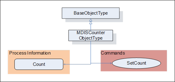
Figure 19 – MDISCounterObjectType
Table 71 defines the structure of an MDISCounterObjectType. Any vendor specified properties that have been implemented within a project should be documented with a similar format and supplied to the DCS vendor. The addition of vendor specific properties will result in a subtype of the MDISCounterObjectType.
Table 71 – MDISCounterObjectType Definition
|
Attribute |
Value |
||||
|
BrowseName |
MDISCounterObjectType |
||||
|
IsAbstract |
False |
||||
|
References |
Node Class |
BrowseName |
DataType |
TypeDefinition |
Other |
|
Subtype of the 0:BaseObjectType |
|
||||
|
0:HasComponent |
Variable |
Count |
0:Number |
0:BaseDataVariableType |
M, RO |
|
0:HasComponent |
Method |
SetCount |
See 6.10.4 |
O |
|
|
ConformanceUnits |
|||||
|
MDIS Counter Object |
|||||
|
MDIS CIMV Base |
|||||
How this value is calculated is server specific. The name of an instance of this ObjectType shall indicate what the object is, such as TotalMotorRuntime, for an example of how this Object is used see 6.9
SetCount Method is used to Set the Count. This Count maybe any counter.
Signature:
SetCount (
[in] 0:Number Initial);
Table 72 – SetCount Method Arguments
|
Argument |
Description |
|
Initial |
The value to initialize the Object Count to, default is 0 |
Method result codes are defined as part of the Call Service (see OPC 10000-4). They are described in Table 124 for ease of reference.
Comments
The SetCount Method command resets the value of the Count Variable. The Count Variable, may immediately start incrementing depending on how it is defined.
Table 73 specifies the AddressSpace representation for the SetCount Method.
Table 73 – SetCount AddressSpace Definition
|
Attribute |
Value |
||||
|
SetCount |
|||||
|
References |
Node Class |
DataType |
TypeDefinition |
Other |
|
|
0:HasProperty |
Variable |
0:InputArguments |
0:Argument[] |
0:PropertyType |
M |
|
ConformanceUnits |
|||||
|
MDIS Counter Object |
|||||
|
MDIS CIMV Base |
|||||
The following section details the generic MDISMotorObjectType structure and defines the properties associated with controlling a Motor. This is in general a vendor and operator independent description, but all users of the MDISMotorObjectType can add vendor specific data. The vendor specific data should be defined as part of a subtype of the MDISMotorObjectType defined in this document. It is assumed that the subsea system is the Server and host of the instance of the MDISMotorObjectType. The DCS based system is the Client in the system. It is assumed that all interactions with the instance of the MDISMotorObjectType are initiated by the Client and are directed to the Server.
The following section details the MDIS generic properties for the MDISMotorObjectType. Implementation shall ensure adherence to Mandatory [M] aspects in order to comply with the MDIS interface standardisation. Optional [O] may or may not be implemented within a project. Figure 20 provides an overview of the MDISMotorObjectType as defined by MDIS, including some nested types. Figure 20 includes all of the items that are inherited from the MDISBaseObjectType.
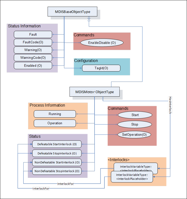
Figure 20 – MDISMotorObjectType
Table 74 defines the structure of an MDISMotorObjectType. Any vendor specified properties that have been implemented within a project should be documented with a similar format and supplied to the DCS vendor. The addition of vendor specific properties will result in a subtype of the MDISMotorObjectType. When an MDISMotorObjectType Instance is disabled the MDISBaseObjectType defaults are followed - no additional values will be available.
Table 74 – MDISMotorObjectType
|
Attribute |
Value |
|||||
|
BrowseName |
MDISMotorObjectType |
|||||
|
IsAbstract |
False |
|||||
|
References |
Node Class |
BrowseName |
DataType |
TypeDefinition |
Other |
|
|
Subtype of the MDISBaseObjectType |
|
|||||
|
0:HasComponent |
Variable |
Running |
0:Boolean |
0:BaseDataVariableType |
M, RO |
|
|
0:HasComponent |
Variable |
Operation |
MotorOperationEnum |
0:BaseDataVariableType |
M, RO |
|
|
0:HasComponent |
Variable |
NonDefeatableStartInterlock |
0:Boolean |
0:BaseDataVariableType |
O, RO |
|
|
0:HasComponent |
Variable |
DefeatableStartInterlock |
0:Boolean |
0:BaseDataVariableType |
O, RO |
|
|
0:HasComponent |
Variable |
NonDefeatableStopInterlock |
0:Boolean |
0:BaseDataVariableType |
O, RO |
|
|
0:HasComponent |
Variable |
DefeatableStopInterlock |
0:Boolean |
0:BaseDataVariableType |
O, RO |
|
|
HasInterlock |
Variable |
<InterlockPlaceholder> |
0:Boolean |
InterlockVariableType |
OP, RO |
|
|
0:HasComponent |
Method |
Start |
See 6.11.4 |
O |
||
|
0:HasComponent |
Method |
Stop |
See 6.11.5 |
O |
||
|
0:HasComponent |
Method |
SetOperation |
See 6.11.6 |
O |
||
|
ConformanceUnits |
||||||
|
MDIS Motor Base |
||||||
Running – Feedback from the motor if it is running (or not). If the motor is running it returns True.
Operation – There are three different operation modes: Auto, Manual and Off. In Auto operation the process sends the Start and Stop command automatically (not from an Operator). In Manual operation the Start and Stop process is executed by the operator manually (e.g. by using the Start and Stop methods). When the operation mode is set to Off, the motor may not be started either automatically or manually. If Manual Operation is supported, then the Start and Stop Methods shall be exposed.
NonDefeatableStartInterlock – The Start command is interlocked and cannot be overridden.
DefeatableStartInterlock – The Start command is interlocked and can be overridden.
NonDefeatableStopInterlock – The Stop command is interlocked and cannot be overridden.
DefeatableStopInterlock – The Stop command is interlocked and can be overridden.
<InterlockPlaceholder > – The number of interlock Variables will change based on the project and even Motor instance. The Variables shall be of InterlockVariableType or a subtype of it. They shall be referenced by a HasInterlock Reference and shall contain an InterlockFor Reference. Clients can use this information to categorise the interlocks appropriately.
The MDISMotorObjectType is a subtype of MDISBaseObjectType and inherit the FaultCode Variable. The MDISMotorObjectType defines the standard FaultCodes (for bits 0-15 as defined in 6.2.2) in Table 75 (currently empty, no additional warning codes defined). All subtypes of this the MDISMotorObjectType will inherit all FaultCodes defined in this table. Subtypes may define additional FaultCodes in their own table.
Table 75 – MDISMotorObjectType FaultCode Values
|
Value |
Bit no. |
Description |
|
|
|
|
The MDISMotorObjectType defines the standard WarningCodes (for bits 0-15 as defined in 6.2.2) in Table 76 (currently empty, no additional warning codes defined). All subtypes of this the MDISMotorObjectType will inherit all WarningCodes defined in this table. Subtypes may define additional WarningCodes in their own table.
Table 76 – MDISMotorObjectType WarningCode Values
|
Value |
Bit no. |
Description |
|
|
|
|
Start Method is used to start the Motor.
Signature:
Start (
[in] 0:Boolean OverrideInterlocks);
Table 77 – Start Method Arguments
|
Argument |
Description |
|
OverrideInterlocks |
Boolean indicating if the Start command should override any interlocks |
Method result codes are defined as part of the Call Service (see OPC 10000-4). They are described in Table 124 for ease of reference. This method shall return Bad_InvalidState if it is invoked and the operation model is not Manual. If the motor is running this command is ignored.
Comments
The Start Method command tries to start the Motor.
Table 67 specifies the AddressSpace representation for the Start Method.
Table 78 – Start AddressSpace Definition
|
Attribute |
Value |
|||||
|
Start |
||||||
|
References |
Node Class |
DataType |
TypeDefinition |
Other |
||
|
0:HasProperty |
Variable |
0:InputArguments |
0:Argument[] |
0:PropertyType |
M |
|
|
ConformanceUnits |
||||||
|
MDIS Motor Start/Stop |
||||||
Stop Method is used to stop the Motor.
Signature:
Stop (
[in] 0:Boolean OverrideInterlocks);
Table 79 – Stop Method Arguments
|
Argument |
Description |
|
OverrideInterlocks |
Boolean indicating if the Stop command should override any interlocks |
Method result codes are defined as part of the Call Service (see OPC 10000-4). They are described in Table 124 for ease of reference. This method shall return Bad_InvalidState if it is invoked and the operation model is not Manual. If the motor is not Running this command is ignored.
Comments
The Stop Method commands the Motor to stop.
Table 80 specifies the AddressSpace representation for the Stop Method.
Table 80 – Stop AddressSpace Definition
|
Attribute |
Value |
|||||
|
Stop |
||||||
|
References |
Node Class |
DataType |
TypeDefinition |
Other |
||
|
0:HasProperty |
Variable |
0:InputArguments |
0:Argument[] |
0:PropertyType |
M |
|
|
ConformanceUnits |
||||||
|
MDIS Motor Start/Stop |
||||||
SetOperation Method is used to set the Operation of the Motor.
Signature:
SetOperation (
[in] MotorOperationEnum Mode);
Table 81 – SetOperation Method Arguments
|
Argument |
Description |
|
Mode |
Mode to operate in (i.e., Auto, Manual or Off) |
Method result codes are defined as part of the Call Service (see OPC 10000-4). They are described in Table 124 for ease of reference.
Comments
The SetOperation Method commands the Operation.
Table 82 specifies the AddressSpace representation for the SetOperation Method.
Table 82 – SetOperation AddressSpace Definition
|
Attribute |
Value |
|||||
|
SetOperation |
||||||
|
References |
Node Class |
DataType |
TypeDefinition |
Other |
||
|
0:HasProperty |
Variable |
0:InputArguments |
0:Argument[] |
0:PropertyType |
M |
|
|
ConformanceUnits |
||||||
|
MDIS Motor Operation |
||||||
The following tables detail the generic properties for the MDISAggregateObjectType; implementation shall ensure adherence to Mandatory [M] aspects to comply with the MDIS interface standardisation. Optional [O] may or may not be implemented within a project. Figure 21 provides an overview of the MDISAggregateObjectType as defined by MDIS. This Object is intended to be the base object for all aggregate ObjectTypes. See section 10.5 for additional details on data aggregation.
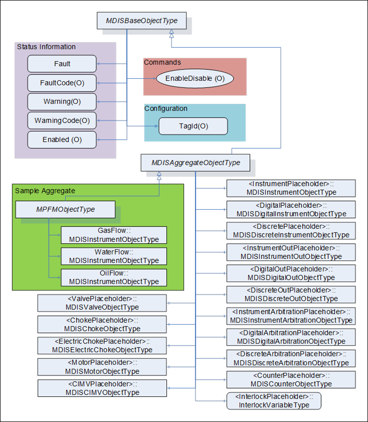
Figure 21 – MDISAggregateObjectType
Table 83 defines the structure of an MDISAggregateObjectType. The MDISAggregateObjectType is a subtype of MDISBaseObjectType and requires that all subtypes include, as a minimum, the Fault information. All other components are Optional and only components that are required by the aggregate are needed.
Table 83 – MDISAggregateObjectType
|
Attribute |
Value |
|||||
|
BrowseName |
MDISAggregateObjectType |
|||||
|
IsAbstract |
True |
|||||
|
References |
Node Class |
BrowseName |
Data Type |
TypeDefinition |
Other |
|
|
Subtype of the MDISBaseObjectType defined in section 6.1.1 |
||||||
|
0:HasComponent |
Object |
<InstrumentPlaceholder> |
|
MDISInstrumentObjectType |
OP |
|
|
0:HasComponent |
Object |
<InstrumentOutPlaceholder> |
|
MDISInstrumentOutObjectType |
OP |
|
|
0:HasComponent |
Object |
<InstrumentArbitrationPlaceholder> |
|
MDISInstrumentArbitrationObjectType |
OP |
|
|
0:HasComponent |
Object |
<DigitalPlaceholder> |
|
MDISDigitalInstrumentObjectType |
OP |
|
|
0:HasComponent |
Object |
<DigitalOutPlaceholder> |
|
MDISDigitalOutObjectType |
OP |
|
|
0:HasComponent |
Object |
<DigitalArbitrationPlaceholder> |
|
MDISDigitalArbitrationObjectType |
OP |
|
|
0:HasComponent |
Object |
<DiscretePlaceholder> |
|
MDISDiscreteInstrumentObjectType |
OP |
|
|
0:HasComponent |
Object |
<DiscreteOutPlaceholder> |
|
MDISDiscreteOutObjectType |
OP |
|
|
0:HasComponent |
Object |
<DiscreteArbitrationPlaceholder> |
|
MDISDiscreteArbitrationObjectType |
OP |
|
|
0:HasComponent |
Object |
<ValvePlaceholder> |
|
MDISValveObjectType |
OP |
|
|
0:HasComponent |
Object |
<ChokePlaceholder> |
|
MDISChokeObjectType |
OP |
|
|
0:HasComponent |
Object |
<ElectricChokePlaceholder> |
|
MDISElectricChokeObjectType |
OP |
|
|
0:HasComponent |
Object |
<MotorPlaceholder> |
|
MDISMotorObjectType |
OP |
|
|
0:HasComponent |
Object |
<CIMVPlaceholder> |
|
MDISCIMVObjectType |
OP |
|
|
0:HasComponent |
Object |
<CounterPlaceholder> |
|
MDISCounterObjectType |
OP |
|
|
HasInterlock |
Variable |
<InterlockPlaceholder> |
|
InterlockVariableType |
OP |
|
|
ConformanceUnits |
||||||
|
MDIS Aggregate Object |
||||||
The MDISAggregateObjectType is an abstract ObjectType; instances of this ObjectType cannot be created. Object instances can only be created of subtypes of this ObjectType. In OPC UA it is legal to add additional Object or Variable Reference(s) to an instance of an Object, (i.e., add Variable or Object to an instance that are not defined in the type), but in MDIS we are restricting this in that a Client is not required to process or handle any Objects or Variables that are not part of a type.
The subtypes of MDISAggregateObjectType are allowed to include other subtypes of MDISAggregateObjectType. For example, a Well that is defined as a subtype of MDISAggregateObjectType might include an MPFMAggregateObjectType which is also a subtype of MDISAggregateObjectType.
<InstrumentPlaceholder> denotes that a subtype of this ObjectType may define any number of Objects of this type as part of a subtype. Each object instance shall have a unique BrowseName and must be of MDISInstrumentObjectType or a subtype of it.
<InstrumentOutPlaceholder> denotes that a subtype of this ObjectType may define any number of Objects of this type as part of a subtype. Each object instance shall have a unique BrowseName and must be of MDISInstrumentOutObjectType or a subtype of it.
<InstrumentArbitrationPlaceholder> denotes that a subtype of this ObjectType may define any number of Objects of this type as part of a subtype. Each object instance shall have a unique BrowseName and must be of MDISInstrumentArbitrationObjectType or a subtype of it.
<DigitalPlaceholder> denotes that a subtype of this ObjectType may define any number of Objects of this type as part of a subtype. Each object instance shall have a unique BrowseName and must be of MDISDigitalInstrumentObjectType or a subtype of it.
<DigitalOutPlaceholder> denotes that a subtype of this ObjectType may define any number of Objects of this type as part of a subtype. Each object instance shall have a unique BrowseName and must be of MDISDigitalOutObjectType or a subtype of it.
<DigitalArbitrationPlaceholder> denotes that a subtype of this ObjectType may define any number of Objects of this type as part of a subtype. Each object instance shall have a unique BrowseName and must be of MDISDigitalArbitrationObjectType or a subtype of it.
<DiscretePlaceholder> denotes that a subtype of this ObjectType may define any number of Objects of this type as part of a subtype. Each object instance shall have a unique BrowseName and must be of MDISDiscreteInstrumentObjectType or a subtype of it.
<DiscreteOutPlaceholder> denotes that a subtype of this ObjectType may define any number of Objects of this type as part of a subtype. Each object instance shall have a unique BrowseName and must be of MDISDiscreteOutObjectType or a subtype of it.
<DiscreteArbitrationPlaceholder> denotes that a subtype of this ObjectType may define any number of Objects of this type as part of a subtype. Each object instance shall have a unique BrowseName and must be of MDISDiscreteArbitrationObjectType or a subtype of it.
<ValvePlaceholder> denotes that a subtype of this ObjectType may define any number of Objects of this type as part of a subtype. Each object instance shall have a unique BrowseName and must be of MDISValveObjectType or a subtype of it.
<ChokePlaceholder> denotes that a subtype of this ObjectType may define any number of Objects of this type as part of a subtype. Each object instance shall have a unique BrowseName and must be of MDISChokeObjectType or a subtype of it.
<ElectricChokePlaceholder> denotes that a subtype of this ObjectType may define any number of Objects of this type as part of a subtype. Each object instance shall have a unique BrowseName and must be of MDISElectricChokeObjectType or a subtype of it.
<MotorPlaceholder> denotes that a subtype of this ObjectType may define any number of Objects of this type as part of a subtype. Each object instance shall have a unique BrowseName and must be of MDISMotorObjectType or a subtype of it.
<CIMVPlaceholder> denotes that a subtype of this ObjectType may define any number of Objects of this type as part of a subtype. Each object instance shall have a unique BrowseName and must be of MDISCIMVObjectType or a subtype of it.
<CounterPlaceholder> denotes that a subtype of this ObjectType may define any number of Objects of this type as part of a subtype. Each object instance shall have a unique BrowseName and must be of MDISCounterObjectType or a subtype of it.
<InterlockPlaceholder> denotes that a subtype of this VariableType may define any number of Variables of this type as part of a subtype. Each Variable instance shall have a unique BrowseName and must be of InterlockVariableType or a subtype of it.
In some systems, a MDIS Server might be on an isolated network, one in which there is no NTP or other source of time synchronization signals. In these systems, the MDIS Server would need to be able to obtain a minimum time synchronization signal from the Client. This ObjectType and associated method is designed to allow this minimum time synchronization. It should only be used if a better time synchronization system, such as NTP, is not available. The accuracy of this type of time synchronization could be in the range of seconds.
If this Object is supported, a single instance of this Object shall exist on a Server. The Object shall have a name TimeSynchronization and the instance shall exist as part of the MDISInformationObject.
The following section details the MDISTimeSyncObjectType. This optional type allows a Client to provide time synchronization information to a Server. The Client can call the SetTime Method periodically to ensure the Server time does not drift. This Method does not return until the time on the Server has been updated or an error is returned.
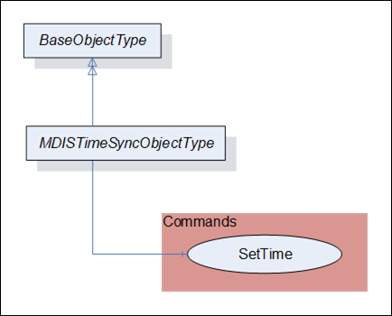
Figure 22 – MDISTimeSyncObjectType
Table 84 defines the structure of an MDISTimeSyncObjectType.
The current time on the Server is available as part of the ServerStatus provided by all OPC UA Servers.
Table 84 – MDISTimeSyncObjectType
|
Attribute |
Value |
||||
|
BrowseName |
MDISTimeSyncObjectType |
||||
|
IsAbstract |
False |
||||
|
References |
Node Class |
BrowseName |
DataType |
TypeDefinition |
Other |
|
Subtype of the BaseObjectType |
|
||||
|
0:HasComponent |
Method |
SetTime |
SetTime Method is defined in 6.13.4 |
M |
|
|
ConformanceUnits |
|||||
|
MDIS Timesync Object |
|||||
SetTime – This method allows a Client to set time on the Server.
SetTime Method (defined in Table 85) is used to set the time on the Server. If an error occurs this Method shall return an error code indicating the failure to set the time (see Table 87).
Signature:
SetTime (
[in] 0:UtcTime TargetTime );
Table 85 – SetTime Method parameters
|
Argument |
Description |
|
TargetTime |
The UTC Time that the Server shall use to update its internal clock. |
Method result codes are defined as part of the Call Service (see OPC 10000-4). They are described in Table 124 for ease of reference.
Comments
The SetTime Method will change the time on the Server. Table 86 specifies the AddressSpace representation for the SetTime Method.
Table 86 – SetTime Method AddressSpace Definition
|
Attribute |
Value |
|||||
|
BrowseName |
SetTime |
|||||
|
References |
Node Class |
BrowseName |
DataType |
TypeDefinition |
Other |
|
|
0:HasProperty |
Variable |
0:InputArguments |
0:Argument[] |
0:PropertyType |
M |
|
|
ConformanceUnits |
||||||
|
MDIS Timesync Object |
||||||
Table 87 – SetTime Result Codes
|
Symbolic Id |
Description |
|
Bad_InvalidTimestamp |
The timestamp is outside the range allowed by the Server or an error occurred setting the Server time. |
MDIS defines flags, general status information and other optional data collections that need to exist in a standard manner on MDIS Servers to allow for easier interoperation between Clients and Servers. This information is provided via the MDISInformationObjectType.
The following section details the MDISInformationObjectType. This ObjectType defines a standard structure for organization of some basic Server information. An instance of this object is required for all versions of MDIS Servers 1.2 and greater. An instance of this ObjectType shall exist under the Objects folder on all OPC UA MDIS Servers. Clients are required to be able to handle Servers which do not contain this object. The Client shall assume any Server that does not contain an instance of this ObjectType is a version 1.1 or 1.0 MDIS Server.
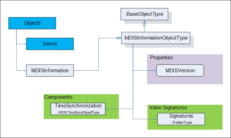
Figure 23 – MDISInformationObjectType
Table 88 defines the structure of an MDISInformationObjectType.
Table 88 – MDISInformationObjectType
|
Attribute |
Value |
||||
|
BrowseName |
MDISInformationObjectType |
||||
|
IsAbstract |
False |
||||
|
References |
Node Class |
BrowseName |
DataType |
TypeDefinition |
Other |
|
Subtype of the BaseObjectType (see OPC 10000-5) |
|
||||
|
0:HasComponent |
Object |
TimeSynchronization |
|
MDISTimeSyncObjectType |
O |
|
0:HasComponent |
Object |
Signatures |
|
0:FolderType |
O |
|
0:HasComponent |
Variable |
MDISVersion |
MDISVersionDataType |
MDISVersionVariableType |
M, RO |
|
ConformanceUnits |
|||||
|
MDIS Information version |
|||||
TimeSynchronization – this is an instance of the MDISTimeSyncObjectType object, that allows a Client to provide time information to a Server if required. See 6.1.16 for additional details.
Signatures is a folder that contains all of the currently available signatures (profiles). The individual signature(s) are stored as FileObjects and the format of the file(s) is vendor specific.
MDISVersion provides information about the version of the MDIS specification that is implemented by the Server. This is provided to assist the Client in determining what should be available and can also be used for automated testing of the Server.